JP6095860B2 - Round sling with RFID (Radio Frequency Identification) pre-fault warning indicator - Google Patents
Round sling with RFID (Radio Frequency Identification) pre-fault warning indicator Download PDFInfo
- Publication number
- JP6095860B2 JP6095860B2 JP2016542271A JP2016542271A JP6095860B2 JP 6095860 B2 JP6095860 B2 JP 6095860B2 JP 2016542271 A JP2016542271 A JP 2016542271A JP 2016542271 A JP2016542271 A JP 2016542271A JP 6095860 B2 JP6095860 B2 JP 6095860B2
- Authority
- JP
- Japan
- Prior art keywords
- rfid
- dedicated
- load
- indicator
- sutoran
- Prior art date
- Legal status (The legal status is an assumption and is not a legal conclusion. Google has not performed a legal analysis and makes no representation as to the accuracy of the status listed.)
- Active
Links
- 230000007257 malfunction Effects 0.000 claims description 15
- 238000011144 upstream manufacturing Methods 0.000 claims description 13
- 230000007547 defect Effects 0.000 claims 5
- 235000021152 breakfast Nutrition 0.000 claims 3
- 238000001514 detection method Methods 0.000 claims 3
- 230000002950 deficient Effects 0.000 claims 1
- 239000011162 core material Substances 0.000 description 85
- 230000006378 damage Effects 0.000 description 11
- 239000000463 material Substances 0.000 description 9
- 229910052751 metal Inorganic materials 0.000 description 6
- 239000002184 metal Substances 0.000 description 6
- 229920002994 synthetic fiber Polymers 0.000 description 6
- 230000000007 visual effect Effects 0.000 description 6
- 238000000034 method Methods 0.000 description 4
- 229920000106 Liquid crystal polymer Polymers 0.000 description 3
- 239000004977 Liquid-crystal polymers (LCPs) Substances 0.000 description 3
- 230000000712 assembly Effects 0.000 description 3
- 238000000429 assembly Methods 0.000 description 3
- 230000007613 environmental effect Effects 0.000 description 3
- 239000004698 Polyethylene Substances 0.000 description 2
- 229920003235 aromatic polyamide Polymers 0.000 description 2
- 239000000835 fiber Substances 0.000 description 2
- -1 polyethylene Polymers 0.000 description 2
- 229920000573 polyethylene Polymers 0.000 description 2
- 230000001681 protective effect Effects 0.000 description 2
- 239000000126 substance Substances 0.000 description 2
- 239000012209 synthetic fiber Substances 0.000 description 2
- 230000003313 weakening effect Effects 0.000 description 2
- 239000004677 Nylon Substances 0.000 description 1
- 229910052782 aluminium Inorganic materials 0.000 description 1
- XAGFODPZIPBFFR-UHFFFAOYSA-N aluminium Chemical compound [Al] XAGFODPZIPBFFR-UHFFFAOYSA-N 0.000 description 1
- 239000004760 aramid Substances 0.000 description 1
- 230000000903 blocking effect Effects 0.000 description 1
- 239000002131 composite material Substances 0.000 description 1
- 238000010276 construction Methods 0.000 description 1
- 238000004519 manufacturing process Methods 0.000 description 1
- 150000002739 metals Chemical class 0.000 description 1
- 239000000203 mixture Substances 0.000 description 1
- 238000012544 monitoring process Methods 0.000 description 1
- 229920001778 nylon Polymers 0.000 description 1
- 229920000728 polyester Polymers 0.000 description 1
- 229920001059 synthetic polymer Polymers 0.000 description 1
- 230000001960 triggered effect Effects 0.000 description 1
Images


Classifications
-
- G—PHYSICS
- G08—SIGNALLING
- G08B—SIGNALLING OR CALLING SYSTEMS; ORDER TELEGRAPHS; ALARM SYSTEMS
- G08B21/00—Alarms responsive to a single specified undesired or abnormal condition and not otherwise provided for
- G08B21/18—Status alarms
-
- B—PERFORMING OPERATIONS; TRANSPORTING
- B66—HOISTING; LIFTING; HAULING
- B66C—CRANES; LOAD-ENGAGING ELEMENTS OR DEVICES FOR CRANES, CAPSTANS, WINCHES, OR TACKLES
- B66C1/00—Load-engaging elements or devices attached to lifting or lowering gear of cranes or adapted for connection therewith for transmitting lifting forces to articles or groups of articles
- B66C1/10—Load-engaging elements or devices attached to lifting or lowering gear of cranes or adapted for connection therewith for transmitting lifting forces to articles or groups of articles by mechanical means
- B66C1/12—Slings comprising chains, wires, ropes, or bands; Nets
- B66C1/14—Slings with hooks
-
- B—PERFORMING OPERATIONS; TRANSPORTING
- B66—HOISTING; LIFTING; HAULING
- B66C—CRANES; LOAD-ENGAGING ELEMENTS OR DEVICES FOR CRANES, CAPSTANS, WINCHES, OR TACKLES
- B66C1/00—Load-engaging elements or devices attached to lifting or lowering gear of cranes or adapted for connection therewith for transmitting lifting forces to articles or groups of articles
- B66C1/10—Load-engaging elements or devices attached to lifting or lowering gear of cranes or adapted for connection therewith for transmitting lifting forces to articles or groups of articles by mechanical means
- B66C1/12—Slings comprising chains, wires, ropes, or bands; Nets
- B66C1/18—Band-type slings
-
- B—PERFORMING OPERATIONS; TRANSPORTING
- B66—HOISTING; LIFTING; HAULING
- B66C—CRANES; LOAD-ENGAGING ELEMENTS OR DEVICES FOR CRANES, CAPSTANS, WINCHES, OR TACKLES
- B66C15/00—Safety gear
-
- D—TEXTILES; PAPER
- D07—ROPES; CABLES OTHER THAN ELECTRIC
- D07B—ROPES OR CABLES IN GENERAL
- D07B1/00—Constructional features of ropes or cables
- D07B1/14—Ropes or cables with incorporated auxiliary elements, e.g. for marking, extending throughout the length of the rope or cable
- D07B1/145—Ropes or cables with incorporated auxiliary elements, e.g. for marking, extending throughout the length of the rope or cable comprising elements for indicating or detecting the rope or cable status
-
- F—MECHANICAL ENGINEERING; LIGHTING; HEATING; WEAPONS; BLASTING
- F16—ENGINEERING ELEMENTS AND UNITS; GENERAL MEASURES FOR PRODUCING AND MAINTAINING EFFECTIVE FUNCTIONING OF MACHINES OR INSTALLATIONS; THERMAL INSULATION IN GENERAL
- F16G—BELTS, CABLES, OR ROPES, PREDOMINANTLY USED FOR DRIVING PURPOSES; CHAINS; FITTINGS PREDOMINANTLY USED THEREFOR
- F16G11/00—Means for fastening cables or ropes to one another or to other objects; Caps or sleeves for fixing on cables or ropes
- F16G11/14—Devices or coupling-pieces designed for easy formation of adjustable loops, e.g. choker hooks; Hooks or eyes with integral parts designed to facilitate quick attachment to cables or ropes at any point, e.g. by forming loops
-
- G—PHYSICS
- G06—COMPUTING; CALCULATING OR COUNTING
- G06K—GRAPHICAL DATA READING; PRESENTATION OF DATA; RECORD CARRIERS; HANDLING RECORD CARRIERS
- G06K19/00—Record carriers for use with machines and with at least a part designed to carry digital markings
- G06K19/06—Record carriers for use with machines and with at least a part designed to carry digital markings characterised by the kind of the digital marking, e.g. shape, nature, code
- G06K19/067—Record carriers with conductive marks, printed circuits or semiconductor circuit elements, e.g. credit or identity cards also with resonating or responding marks without active components
- G06K19/07—Record carriers with conductive marks, printed circuits or semiconductor circuit elements, e.g. credit or identity cards also with resonating or responding marks without active components with integrated circuit chips
- G06K19/0716—Record carriers with conductive marks, printed circuits or semiconductor circuit elements, e.g. credit or identity cards also with resonating or responding marks without active components with integrated circuit chips at least one of the integrated circuit chips comprising a sensor or an interface to a sensor
-
- G—PHYSICS
- G06—COMPUTING; CALCULATING OR COUNTING
- G06K—GRAPHICAL DATA READING; PRESENTATION OF DATA; RECORD CARRIERS; HANDLING RECORD CARRIERS
- G06K19/00—Record carriers for use with machines and with at least a part designed to carry digital markings
- G06K19/06—Record carriers for use with machines and with at least a part designed to carry digital markings characterised by the kind of the digital marking, e.g. shape, nature, code
- G06K19/067—Record carriers with conductive marks, printed circuits or semiconductor circuit elements, e.g. credit or identity cards also with resonating or responding marks without active components
- G06K19/07—Record carriers with conductive marks, printed circuits or semiconductor circuit elements, e.g. credit or identity cards also with resonating or responding marks without active components with integrated circuit chips
- G06K19/077—Constructional details, e.g. mounting of circuits in the carrier
- G06K19/07749—Constructional details, e.g. mounting of circuits in the carrier the record carrier being capable of non-contact communication, e.g. constructional details of the antenna of a non-contact smart card
- G06K19/07758—Constructional details, e.g. mounting of circuits in the carrier the record carrier being capable of non-contact communication, e.g. constructional details of the antenna of a non-contact smart card arrangements for adhering the record carrier to further objects or living beings, functioning as an identification tag
-
- G—PHYSICS
- G06—COMPUTING; CALCULATING OR COUNTING
- G06K—GRAPHICAL DATA READING; PRESENTATION OF DATA; RECORD CARRIERS; HANDLING RECORD CARRIERS
- G06K19/00—Record carriers for use with machines and with at least a part designed to carry digital markings
- G06K19/06—Record carriers for use with machines and with at least a part designed to carry digital markings characterised by the kind of the digital marking, e.g. shape, nature, code
- G06K19/067—Record carriers with conductive marks, printed circuits or semiconductor circuit elements, e.g. credit or identity cards also with resonating or responding marks without active components
- G06K19/07—Record carriers with conductive marks, printed circuits or semiconductor circuit elements, e.g. credit or identity cards also with resonating or responding marks without active components with integrated circuit chips
- G06K19/077—Constructional details, e.g. mounting of circuits in the carrier
- G06K19/07749—Constructional details, e.g. mounting of circuits in the carrier the record carrier being capable of non-contact communication, e.g. constructional details of the antenna of a non-contact smart card
- G06K19/07798—Constructional details, e.g. mounting of circuits in the carrier the record carrier being capable of non-contact communication, e.g. constructional details of the antenna of a non-contact smart card part of the antenna or the integrated circuit being adapted for rupturing or breaking, e.g. record carriers functioning as sealing devices for detecting not-authenticated opening of containers
-
- G—PHYSICS
- G06—COMPUTING; CALCULATING OR COUNTING
- G06K—GRAPHICAL DATA READING; PRESENTATION OF DATA; RECORD CARRIERS; HANDLING RECORD CARRIERS
- G06K7/00—Methods or arrangements for sensing record carriers, e.g. for reading patterns
- G06K7/10—Methods or arrangements for sensing record carriers, e.g. for reading patterns by electromagnetic radiation, e.g. optical sensing; by corpuscular radiation
- G06K7/10009—Methods or arrangements for sensing record carriers, e.g. for reading patterns by electromagnetic radiation, e.g. optical sensing; by corpuscular radiation sensing by radiation using wavelengths larger than 0.1 mm, e.g. radio-waves or microwaves
- G06K7/10366—Methods or arrangements for sensing record carriers, e.g. for reading patterns by electromagnetic radiation, e.g. optical sensing; by corpuscular radiation sensing by radiation using wavelengths larger than 0.1 mm, e.g. radio-waves or microwaves the interrogation device being adapted for miscellaneous applications
-
- D—TEXTILES; PAPER
- D07—ROPES; CABLES OTHER THAN ELECTRIC
- D07B—ROPES OR CABLES IN GENERAL
- D07B2301/00—Controls
- D07B2301/25—System input signals, e.g. set points
- D07B2301/259—Strain or elongation
Landscapes
- Engineering & Computer Science (AREA)
- Physics & Mathematics (AREA)
- Mechanical Engineering (AREA)
- Microelectronics & Electronic Packaging (AREA)
- General Physics & Mathematics (AREA)
- Computer Hardware Design (AREA)
- Theoretical Computer Science (AREA)
- Health & Medical Sciences (AREA)
- Toxicology (AREA)
- General Engineering & Computer Science (AREA)
- Electromagnetism (AREA)
- General Health & Medical Sciences (AREA)
- Artificial Intelligence (AREA)
- Computer Vision & Pattern Recognition (AREA)
- Business, Economics & Management (AREA)
- Emergency Management (AREA)
- Apparatus For Radiation Diagnosis (AREA)
- Emergency Alarm Devices (AREA)
- Control Of Conveyors (AREA)
- Load-Engaging Elements For Cranes (AREA)
Description
本発明は概して、重い貨物の引き上げ、移動および搬送に用いられる産業用スリングに関するものであり、より具体的には、RFIDに基づく警告インジケータに関するものである。この警告インジケータは、負荷を軽減せずにこのままスリングを使用し続けると、スリングが壊れるかもしれない状況であることを使用者に知らせるものである。 The present invention relates generally to industrial slings used for lifting, moving and transporting heavy cargo, and more particularly to RFID based warning indicators. This warning indicator informs the user that the sling may break if the sling continues to be used without reducing the load.
本明細書中では、特許、公開された出願、技術記事および学術記事を含む様々な出版物が引用されている。これらの各々は、参照によりあらゆる目的のために、その全てが援用される。 In this specification, various publications are cited, including patents, published applications, technical articles and academic articles. Each of these is incorporated by reference in its entirety for all purposes.
産業用スリングは、典型的には、金属または合成材料により製造されている。ワイヤロープスリングは、一般的に、複数の金属ストランドにより形成されている。この複数の金属ストランドは、互いにより合わされ、大きな金属スリーブまたはカラーにより保護されている。合成スリングは、通常、引き上げコアと、このコアを保護するための外側カバーとにより構成されている。引き上げコアは、合成繊維のより線により形成されている。よく知られている合成スリングの1つとして、ラウンドスリングある。ラウンドスリングでは、引き上げコアが連続ループをなし、円形または楕円形の外形を有している。 Industrial slings are typically made of metal or synthetic materials. The wire rope sling is generally formed of a plurality of metal strands. The plurality of metal strands are twisted together and protected by a large metal sleeve or collar. Synthetic slings are usually composed of a raised core and an outer cover for protecting the core. The lifting core is formed by a strand of synthetic fiber. One well-known synthetic sling is a round sling. In a round sling, the lifting core forms a continuous loop and has a circular or elliptical profile.
最近の産業用スリングは、スリングの破壊または損傷に起因する不具合および積載量の低下を経験しているかもしれない。これは、例えば、現在または過去の使用の間の疲労、過度な引っ張り、あるいは過積載によるものである。ラウンドスリングは、その定格荷重を超える過積載の状態にさらされると、貨物が耐荷重コア材料の繊維をその降伏点を超えて引き延ばした場合には、永久に損傷を受けた/変形した状態となり得る。合成繊維スリングは、最大に伸ばした状態で、その引張強度または重量引き上げ能力を超えて過積載状態になると、疲労すると考えられ、その通常の強度および耐荷重能力には決して戻り得ないかもしれない。 Modern industrial slings may have experienced failures and reduced load due to sling breaking or damage. This is due, for example, to fatigue during current or past use, excessive pulling, or overloading. When a round sling is exposed to overload conditions that exceed its rated load, it becomes permanently damaged / deformed if the cargo stretches the fibers of the load-bearing core material beyond its yield point. obtain. A synthetic fiber sling is considered to fatigue if it is fully stretched and overloaded beyond its tensile strength or weight lifting capacity and may never return to its normal strength and load carrying capacity .
スリングには、通常、個々のスリングに対して規定の積載能力(定格荷重)が与えられている。これにより、使用者はスリングの引き上げ能力または積載能力を知る。それにも関わらず、スリングを装備して使用する間に突発的に、または使用者が危険な手抜きをおこなったために、このスリングの能力を超えてしまうことが時々ある。しばしば、スリング材料への過積載、疲労または損傷は容易に表れないかもしれない。これは、特に、スリングの大きさまたは長さが大きいことにより、あるいは、耐荷重コアが外側のカバーの中に隠れていることによる。ラウンドスリングが疲労するか、または構造的に変化してしまった場合、スリングはもはやその最大規定積載量の荷物を持ち上げることができなくなってしまうかもしれない。そのような状況は、その損傷したスリングを使用する操作員または綱具員にとって脅威となり得る。 Slings are usually given a specified load capacity (rated load) for each sling. As a result, the user knows the lifting ability or loading ability of the sling. Nevertheless, sometimes the capacity of this sling can be exceeded, either suddenly while wearing the sling, or because the user has taken a dangerous cut. Often, overloading, fatigue or damage to the sling material may not appear easily. This is in particular due to the large size or length of the sling or because the load bearing core is hidden in the outer cover. If the round sling is fatigued or structurally changed, the sling may no longer be able to lift its maximum load capacity. Such a situation can be a threat to an operator or brace using the damaged sling.
商業的に製造されたラウンドスリングの多くは、事前不具合インジケータを備えている。そのような不具合インジケータは、実際には、同じ製造方法により製造された同じタイプのスリングの間でさえも一致していない。したがって、当該技術分野では、より一致し、より信頼性の高いスリング事前不具合インジケータが必要とされている。 Many of the commercially manufactured round slings are equipped with a pre-failure indicator. Such failure indicators are in fact not consistent even between the same type of sling manufactured by the same manufacturing method. Therefore, there is a need in the art for a more consistent and more reliable sling prefailure indicator.
本開示は、ラウンドスリング事前警告システムに特徴付けられるものである。いくつかの態様では、このシステムは、耐荷重コアを含むラウンドスリングと、少なくとも1つのRFID(radio frequency identification)タグが付けられたインジケータヤーン(indicator yarn)と、1つ以上のRFIDセンサと、RFID信号受信機とを備えている。RFIDセンサは、RFID信号受信機に無線信号をおくるための送信機を有している。このシステムは、更に、専用ストランドを有する事前不具合インジケータアッセンブリを備えていてもよい。この専用ストランドは両端にアイループを有しており、この両端のアイループは1つ以上のリングを介して連結されている。このリングは、耐荷重コアの最大積載量よりも小さい負荷で壊れる。専用ストランドは、コアの近傍に配置されていることが好ましい。インジケータヤーンは、専用ストランドに連結されていることが好ましい。インジケータヤーンは、使用者またはラウンドスリングに見えやすいように、明るく色づけされていることが好ましい。RFID信号受信機は、携帯電話、タブレットコンピュータあるいはその他の形式のワイヤレスコンピュータなどの携帯用のワイヤレス機器を含んでいてもよく、RFID信号受信機は、ラウンドスリングが事前不具合の状態にあることを、可聴式のアラームの発生、警告表示および/または触覚式のアラームの発生のうちの1つ以上により使用者に知らせる。 The present disclosure is characterized by a round sling pre-warning system. In some aspects, the system includes a round sling including a load bearing core, an indicator yarn with at least one radio frequency identification (RFID) tag, one or more RFID sensors, and an RFID And a signal receiver. The RFID sensor has a transmitter for sending a radio signal to the RFID signal receiver. The system may further comprise a pre-failure indicator assembly having a dedicated strand. The dedicated strand has eye loops at both ends, and the eye loops at both ends are connected via one or more rings. This ring breaks with a load smaller than the maximum load capacity of the load bearing core. The dedicated strand is preferably disposed in the vicinity of the core. The indicator yarn is preferably connected to a dedicated strand. The indicator yarn is preferably brightly colored so that it can be easily seen by the user or the round sling. The RFID signal receiver may include a portable wireless device such as a mobile phone, tablet computer or other type of wireless computer, and the RFID signal receiver indicates that the round sling is in a pre-failure state, The user is informed by one or more of an audible alarm occurrence, a warning indication and / or a tactile alarm occurrence.
いくつかの態様では、コアは、開口を有するカバーに収容されており、カバーの開口をインジケータヤーンの端部が通ってインジケータヤーンの端部がカバーの外側に露出されている。RFIDタグは、インジケータヤーンの端部の可視/外側の位置に付けられていてもよい。RFIDセンサは、開口近傍にあってもよい。インジケータヤーンは、複数のRFIDタグを有していてもよく、あるいは、少なくとも2つ、少なくとも3つ、少なくとも4つ、あるいは4つより多くRFIDタグを有していてもよい。 In some embodiments, the core is housed in a cover having an opening through which the end of the indicator yarn passes through the opening of the cover and the end of the indicator yarn is exposed to the outside of the cover. The RFID tag may be attached at a visible / outside position at the end of the indicator yarn. The RFID sensor may be in the vicinity of the opening. The indicator yarn may have a plurality of RFID tags, or may have at least 2, at least 3, at least 4, or more than four RFID tags.
ラウンドスリングは1経路または2経路ラウンドスリングであってもよい。所定の2経路ラウンドスリングでは、それぞれの経路が耐荷重コアと、1つ以上のRFIDタグが付けられたインジケータヤーンと、1つ以上のRFIDセンサとを備えている。RFIDセンサは、RFID信号受信機に無線信号をおくるための送信機を有している。それぞれの経路は、更に、専用ストランドを有する事前不具合インジケータアッセンブリを備えていてもよい。この専用ストランドは両端にアイループを有しており、この両端のアイループは1以上のリングを介して連結されている。このリングは、耐荷重コアの最大積載量よりも小さい負荷で壊れる。専用ストランドは、コアの近傍に配置されていることが好ましい。インジケータヤーンは、専用ストランドに連結されていることが好ましい。インジケータヤーンは、使用者またはラウンドスリングに見えやすいように、明るく色づけされていることが好ましい。 The round sling may be a one-path or two-path round sling. In a given two-path round sling, each path comprises a load-bearing core, an indicator yarn with one or more RFID tags, and one or more RFID sensors. The RFID sensor has a transmitter for sending a radio signal to the RFID signal receiver. Each path may further comprise a pre-failure indicator assembly having a dedicated strand. The dedicated strand has eye loops at both ends, and the eye loops at both ends are connected via one or more rings. This ring breaks with a load smaller than the maximum load capacity of the load bearing core. The dedicated strand is preferably disposed in the vicinity of the core. The indicator yarn is preferably connected to a dedicated strand. The indicator yarn is preferably brightly colored so that it can be easily seen by the user or the round sling.
いくつかの態様では、システムは、耐荷重コアを含むラウンドスリングと、事前不具合インジケータアッセンブリと、1以上のRFIDセンサと、RFID信号受信機とを備えている。事前不具合インジケータアッセンブリは、コア近傍に配置された専用ストランドと、専用ストランドに付けられた1またはそれ以上のRFIDタグを有している。専用ストランドは両端にアイループを有しており、この両端のアイループは1つ以上のリングを介して連結されている。このリングは、耐荷重コアの最大積載量よりも小さい負荷で壊れる。RFIDセンサは、RFID信号受信機に信号を送るための送信機を含んでいる。RFID信号受信機は、携帯電話、タブレットコンピュータあるいはその他の形態の無線コンピュータなどの携帯用のワイヤレス機器内を含んでいてもよく、RFID信号受信機は、ラウンドスリングが事前不具合の状態にあることを、可聴式のアラームの発生、警告表示および/または触覚式のアラームの発生のうちの1つ以上により使用者に知らせる。 In some aspects, the system includes a round sling that includes a load bearing core, a pre-failure indicator assembly, one or more RFID sensors, and an RFID signal receiver. The pre-failure indicator assembly has a dedicated strand located near the core and one or more RFID tags attached to the dedicated strand. The dedicated strand has eye loops at both ends, and the eye loops at both ends are connected via one or more rings. This ring breaks with a load smaller than the maximum load capacity of the load bearing core. The RFID sensor includes a transmitter for sending signals to an RFID signal receiver. The RFID signal receiver may include within a portable wireless device such as a mobile phone, tablet computer or other form of wireless computer, and the RFID signal receiver may indicate that the round sling is in a pre-failure state. The user is informed by one or more of an audible alarm occurrence, a warning indication and / or a tactile alarm occurrence.
いくつかの態様では、システムは、耐荷重コアを含むラウンドスリングと、事前不具合インジケータアッセンブリとを備えている。事前不具合インジケータアッセンブリは、専用ストランドを含んでいる。専用ストランドは両端にアイループを有しており、この両端のアイループは1つ以上のリングを介して連結されている。このリングは、耐荷重コアの最大積載量よりも小さい負荷で壊れる。リングは、1つ以上のアクティブRFIDタグを含んでいることが好ましい。1つ以上のRFIDタグは、必要に応じてRFIDタグから送られる信号をブロックするためのシールドを含んでいてもよい。シールドが破壊されると、信号は破壊された箇所を通じて漏れ、この自由になった信号が検出されてもよい。必要に応じて、このシステムは、専用ストランドに連結されたインジケータヤーンを備えていてもよい。このシステムは、RFID信号受信機も備えている。 In some aspects, the system includes a round sling that includes a load bearing core and a pre-failure indicator assembly. The pre-failure indicator assembly includes a dedicated strand. The dedicated strand has eye loops at both ends, and the eye loops at both ends are connected via one or more rings. This ring breaks with a load smaller than the maximum load capacity of the load bearing core. The ring preferably includes one or more active RFID tags. One or more RFID tags may include a shield to block signals sent from the RFID tags as needed. When the shield is broken, the signal leaks through the broken point and this freed signal may be detected. If desired, the system may comprise an indicator yarn connected to a dedicated strand. The system also includes an RFID signal receiver.
専用ストランドは、複数のRFIDタグを含んでいてもよく、あるいは、少なくとも2つ、少なくとも3つ、あるいは少なくとも4つ、あるいは4つより多くRFIDタグを含んでいてもよい。ラウンドスリングは、2つ以上のRFIDセンサを備えていてもよい。インジケータヤーンは、その端部がカバーの外側に露出された状態で、専用ストランドに付けられていてもよい。 The dedicated strand may include a plurality of RFID tags, or may include at least two, at least three, or at least four, or more than four RFID tags. A round sling may comprise more than one RFID sensor. The indicator yarn may be attached to a dedicated strand with its end exposed on the outside of the cover.
ラウンドスリングは、1経路または2経路ラウンドスリングであってもよい。所定の2経路ラウンドスリングでは、各々の経路が、耐荷重コアと、事前不具合インジケータアッセンブリと、1つ以上のRFIDセンサとを含んでいる。事前不具合インジケータアッセンブリは、コア近傍に配置された専用ストランドと専用ストランドに付けられた1つ以上のRFIDタグを有している。専用ストランドは両端にアイループを有しており、この両端のアイループは1つ以上のリングを介して連結されている。このリングは、耐荷重コアの最大積載量よりも小さい負荷で壊れる。RFIDセンサは、RFID信号受信機に信号を送るための送信機を含んでいる。 The round sling may be a one-path or two-path round sling. In a given two-path round sling, each path includes a load bearing core, a pre-failure indicator assembly, and one or more RFID sensors. The pre-failure indicator assembly has a dedicated strand disposed near the core and one or more RFID tags attached to the dedicated strand. The dedicated strand has eye loops at both ends, and the eye loops at both ends are connected via one or more rings. This ring breaks with a load smaller than the maximum load capacity of the load bearing core. The RFID sensor includes a transmitter for sending signals to an RFID signal receiver.
本発明は、添付の図面と関連付けて読んだときに、以下の詳細な説明から最もよく理解される。一般的な方法にしたがって、図面の様々な特徴は原寸に比例していないことを強調する。一方、様々な特徴の大きさは、明確にするために、任意に拡大または縮小している。以下の図面にこれらの図面が含まれる。 The invention is best understood from the following detailed description when read in conjunction with the accompanying drawings. It is emphasized that, according to common practice, the various features of the drawings are not to scale. On the other hand, the sizes of the various features are arbitrarily expanded or reduced for clarity. These drawings are included in the following drawings.
本開示の形態に関連する様々な語は、明細書および特許請求の範囲を通して用いられている。そのような語は、別段の指示がない限り、当該技術分野での通常の意味を有する。他の具体的に定義された語は、ここで設けられた定義と一致するように解釈される。 Various terms related to the forms of the disclosure are used throughout the specification and the claims. Such terms have their ordinary meaning in the art unless otherwise indicated. Other specifically defined terms are to be construed as consistent with the definitions provided herein.
本開示は、例えば、耐荷重性面での過剰な引き延ばし、あるいは過積載に起因して、産業用のラウンドスリングに使用中の不具合が生じるかどうかを決定するためのシステムまたは方法に関する。基本的特徴は、ラウンドスリングの耐荷重面の状態に関する情報を使用者に伝えるためのRFIDタグおよびセンサを含んでいる。ラウンドスリングは、ラウンドスリングおよび米国特許7,661,737号公報の犠牲リング型事前不具合インジケータシステムを備えていてもよい。 The present disclosure relates to a system or method for determining whether a failure in use occurs in an industrial round sling due to, for example, excessive stretching in terms of load bearing or overloading. Basic features include RFID tags and sensors to communicate information about the condition of the load bearing surface of the round sling to the user. The round sling may comprise a round sling and a sacrificial ring type pre-fail indicator system of US Pat. No. 7,661,737.
図1Aは、1経路ラウンドスリング10の限定されない例の一つを表している。1経路ラウンドスリング10は、耐荷重コア12を備えている。耐荷重コア12には、複数のストランド13が含まれていてもよく(図2)、これは金属または合成ポリマーまたは複合材料を含む適当な材料のいずれから作られていてもよい。コア12は、1つ以上の天然または合成材料を含んでいてもよい。天然または合成材料は、ポリエステル(polyester)、ポリエチレン(polyethylene)、ナイロン(nylon)、K−Spec(登録商標、Slingmax, Inc.、権利化された繊維の混合物)、高弾性ポリエチレン、液晶ポリマー(LCP : liquid crystal polymer)、アラミド(aramid)、パラアラミド(para-aramid)または他の適当な合成材料などである。コア12の材料は、スリング10が持ち上げることができるように設計された最大重量およびスリング10が使用される環境に関係していてもよい。一般的に、合成ストランド13は、ワイヤロープまたは金属チェーンスリングに比べて、高い持ち上げ力、高い破壊強度、より軽量化、高温耐性および高耐久性を有している。
FIG. 1A represents one non-limiting example of a one-path
コア12は、保護カバー14内に収容されている。コア12は、一般的に、持ち上げられる貨物のほぼ全重量を支える。カバー14は、一般的に、コア12が厳しい環境状況に晒されるのを保護するだけでなく、コア12への物理的な損傷を防ぐ。厳しい環境状況は、例えば、熱、湿気、紫外光、腐食性化学物質、気体物質、あるいはコア12の材料を損傷させるまたは弱らせるような他の環境状況である。物理的な損傷は、例えば、摩耗によるもの、貨物の鋭利な角によるものである。
The
1経路ラウンドスリング10は、インジケータヤーン18もラベル16も含んでいてもよい。カバー14は、開口を備えていてもよく、この開口をインジケータヤーン18が通っていてもよい。このとき、インジケータヤーン18の所定の長さおよびその一方の端部がカバー14の内側にあり、インジケータヤーン18の所定の長さおよびその他方の端部がカバー14の外側にある。開口はラベル16の下にあってもよいが、カバー14の適当な位置のいずれに配置されていてもよい。開口がラベル16の下にある態様では、ヤーン18がラベル16から外側に延びていてもよく、一方の端部の所定の長さが、カバー14の表面をこえ、自由に延びていてもよい。ヤーン18は、明るい色であることが好ましい。明るい色は、黄、オレンジ、赤またはこれらの組合せであってもよく、あるいは、使用者が可視のヤーン18の端部を監視できるような他の適当な可視の色、または対照色である。例えば、ラウンドスリング10が過剰に引き延ばされる、あるいは過積載の状態にされることが起こったときに、ヤーン18がラベル16内に引っ張られるにつれて、ヤーン18の可視の部分が短くなってもよい。このヤーン18の可視の部分が短くなったことが、使用者にラウンドスリング10が過剰に引き延ばされ、あるいは過積載であることを知らせる。この意味で、インジケータヤーン18は、後述のRFID事前不具合警告システム40のいくつかの形態では、重複物として機能してもよい。同様に、インジケータヤーン18がそのようなシステム40の部品を含んでいてもよい。
The one-path
図1Bは、2経路ラウンドスリング10aの限定されない例の一つを表している。図1Aおよび図1Bに示されているように、1経路ラウンドスリング10と2経路ラウンドスリング10aの基本的な特徴は、同じである。そして、例えば、2経路ラウンドスリング10aは、2つの分離した耐荷重コア12および12aと、2つの分離したカバー14および14aと、2つの分離したラベル16および16aと、2つの分離したインジケータヤーン18および18aとを備えている。
FIG. 1B represents one non-limiting example of a two-path round sling 10a. As shown in FIGS. 1A and 1B, the basic features of the one-path
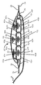
図2は、図1Aに示したラウンドスリング10の2−2線に沿った断面図を表している。断面は、カバー14内に収容されたコア12を表している。断面は、複数のストランド13から成っているコア12も表している。ストランド13は、複数のストランド13の連続した平行ループからなり、1つのコア12または複数のコア(図示せず)を形成していてもよい。これらの全ては、カバー14内に含まれている。詳細については後述するが、いくつかの好ましい態様では、ラウンドスリング10は、コア12に関連する専用ストランド24を備えている。専用ストランド24は、コア12を形成するストランド13とは異なっていることが好ましく、専用ストランド24は、事前不具合インジケータアッセンブリ20の一部であってもよい。
FIG. 2 shows a cross-sectional view along the line 2-2 of the
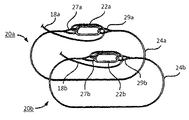
事前不具合インジケータアッセンブリ20の限定されない例が図3に示されている。図3は、側面図であり、コア12のない状態である(説明のために、コア12のない状態で示されている)。1経路ラウンドスリング10または2経路ラウンドスリング10aは、事前不具合インジケータアッセンブリ20を備えていてもよい。2経路ラウンドスリング10aのそれぞれの経路がその固有の事前不具合インジケータアッセンブリ20およびそのそれぞれの部品を備えていてもよい。
A non-limiting example of the
事前不具合インジケータアッセンブリ20は、少なくとも1つの専用ストランド24を含んでおり、専用ストランド24は、第1端26および第2端28を有している。第1端26は第1アイループ27を有し、第2端は第2アイループ97を有している。第1アイループ27と第2アイループ29とは、リング22により間接的に連結されている。リング22は、第1アイループ27と第2アイループ29との間にあり、アイループ27および29それぞれとリング22とは鎖状の連結を形成している。いくつかの態様では、例えばヤーン18が、第1アイループ27または第2アイループ29のどちらかに連結されることにより、インジケータヤーン18が事前不具合インジケータアッセンブリ20に連結されている。専用ストランド24は、コアストランド13の材料と同じ材料により形成されていることが好ましいが、いくつかの態様では、異なる材料により形成されていてもよい。
The
事前不具合インジケータアッセンブリ20は、カバー14の下に配置されていてもよく、ラベル16の下に配置されていてもよい。専用ストランド24は、コア12に最も近いことが好ましく、例えば、1つ以上のコアストランド13の周囲で撚られていてもよく、あるいは、図2に示したように、コア12の隣にあってもよい。いくつかの態様では、専用ストランド24は、カバー14の内側に付けられている。ラウンドスリング10が長期間にわたり使用されている時、特定の位置がすり減ってきてしまう虞がある。例えば、ラウンドスリング10がクレーンのフックに掛けられている場合である。したがって、耐荷重コア12のまわりで、カバー14を回転させることが望まれるかもしれない。専用ストランド24はカバー14の内側に固定することにより、カバー14を動かしても(意図的に、もしくは、非意図的に)事前不具合インジケータアッセンブリ20の動作に影響を与えない。
The
第1アイループ27と第2アイループ29とがリング22を介して連結されているとき、専用ストランド24とリング22とは連続ループを形成する。分離した専用ストランド24の形は、一般的に、コアストランド13によって形成される連続平行ループの形(例えば、一般的に円形、または楕円形)に適合する形である。リング22は、いずれの適当な形状を含む。
When the
好ましくは、リング22はコア12よりも低い張力を有している。例えば、リング22は、コアストランド13とは異なる材料により形成されていてもよい。あるいは、物理的に弱めるための切り込みや刻み目などをリング22内に形成し、このような壊れやすい複数の部分をリング22が有するようにしてもよい。あるいは、リング22がコアストランド13よりも小さな直径を有するようにしてもよい。
Preferably, the
事前不具合インジケータ20は、引き金となり、それにより、綱具員または他の使用者に、ラウンドスリング10が過剰に引き延ばされている状態、あるいは過積載の状態(例えば、ラウンドスリング10がその完全性が損なわれる力を受けている)であることを知らせるように設計されている。この力は、ラウンドスリングの定格荷重の約4倍であってもよい。ラウンドスリング10に、推奨積載量を超える負荷がかかっているとき、コアストランド13(したがって、コア12)または専用ストランド24のどちらかに損傷が生じる前に、リング22が壊れる。リング22が壊れると、第1アイループ27と第2アイループ29とが反対方向に動きはじめて、お互いに離れていく。そして、専用ストランド24の第1および第2端26,28だけでなく、これらアイループ27および29間の物理的な距離も大きくなる。いくつかの態様では、リング22はコア12の張力(例えば最大積載能力)の約70%から約90%で壊れる。いくつかの好ましい態様では、リング22は、コア12の張力の約70%、約75%または約80%で壊れる。一般的に、リング22はコア12に損傷が生じる前に壊れるように設計されており、それにより、使用者に、現在の使用方法によるラウンドスリング10の使用を中止するか、もし、続けるのであれば、ラウンドスリング10が永久的に損傷することを警告する。リング22の損傷は、これに限らないが、破壊、粉砕、引き延ばし、あるいは他の方法で、リング22が専用ストランド24の端をもはや橋渡しできないように、あるいは、専用ストランド24の端を一定の距離に維持することができないように破壊されることを含む。
The
事前不具合インジケータアッセンブリ20が、インジケータヤーン18を含む態様では、アイループ27,29が離れていくとき、ラベル16を超えて延在し、使用者に見えているヤーン18の一部が、その端が見えなくなるまで、カバーラベル16もしくはカバー14内に引き戻される。もし、ヤーン18の末端が見えなくなる、あるいは、見える末端部分が著しく短くなると、検査官または綱具員はすぐに、ラウンドスリング10が過剰に引き延ばされている状態、あるいは過積載の状態にあるかもしれないと決定することができる。
In embodiments where the
いくつかの態様では、事前不具合インジケータアッセンブリ20は、複数のリング22を有している。例えば、図4に示したように、アッセンブリ20は、第1アイループ27と第2アイループ29との間に、互いに連結された3つのリング22a,22b,22cを有していてもよい。2経路ラウンドスリング10aは、図5に示したように、2つの事前不具合インジケータアッセンブリ20aおよび20bを有しており、1つの経路に1つのアッセンブリ20を有している。事前不具合インジケータアッセンブリ20a,20bそれぞれの部品は、上述したように、同じである。
In some aspects, the
ラウンドスリング10は、RFID事前不具合警告システム40を備えていることが好ましい。RFID事前不具合警告システム40は、一般的に、1つ以上のRFIDタグ42と、少なくとも1つのRFIDセンサ44と、少なくとも1つのRFID信号受信機46とを含んでいる。RFIDセンサ44は、一般的にRFIDタグ42を検出するために機能する。例えば、RFIDタグ42がRFIDセンサ44近傍に移動するとき、あるいは、RFIDセンサ44のそばを通りすぎるとき、RFIDタグ42が検出された時点で、RFIDセンサ44は、RFID信号受信機46に受信される信号を発信する。1つ以上のRFIDタグ42は、パッシブRFIDタグ42であってもよく、例えば、RFIDタグ42は固有の電源を有していないが、RFIDセンサ44からの放出物近傍に移動した時にRFIDタグ42に電力を供給するための電流を発生させる部品を含んでいてもよい。1つ以上のRFIDタグ42は、アクティブRFIDタグ42またはセミアクティブRFIDタグ42であってもよく、これらはそれぞれRFIDタグ42に電力を供給するための電源、このましくはバッテリを有していてもよい。アクティブRFIDタグ42は、信号を送るためにその電源を利用してもよく、セミアクティブRFIDタグ42は信号をおくるためにRFIDセンサ44からの放出物を利用してもよい。RFIDタグ42は、信号をブロックするためのシールド43を含んでいてもよい。シールド43は、例えば、RFIDタグ42がアクティブである形態において有用であってもよい。そして、ラウンドスリング10の部品(例えば、コアストランド13、コア12、事前インジケータアッセンブリ20、リング22など)の1つ以上が、ラウンドスリング10が破損する危険性があるほどの損傷を受けていることを示すものとして、シールド43が破壊されたときのみ信号を検出することが望ましい。
The
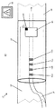
RFID事前不具合警告システム40の限定されない例の1つが図6Aから図6Cに示されている。RFID事前不具合警告システム40は、ラウンドスリング10または10aの外周付近のどこに配置されていてもよいが、図6Aに示したように、ラウンドスリング10または10aのラベル16の領域に位置していてもよい。ここで示した形態では、インジケータヤーン18がRFID事前不具合警告システム40の一部を形成しており、RFIDタグ42がインジケータヤーン18に付けられている。必ずしも必要でないが、インジケータヤーン18は、上述のように、事前不具合インジケータアッセンブリ20(図示せず)に連結されていてもよい。RFIDセンサ44は、無線信号を送信可能な送信機43またはトランシーバ43を含んでおり、この信号は、ラウンドスリング10の状態に関する情報を送信する。RFIDセンサ44はカバー14に付けられていてもよいが、RFIDセンサ44はラベル16に付けられていることが好ましい。この場合、RFIDセンサ44は、RFIDタグ42を検出可能な限り、カバー14の内側であってもよく、外側であってもよい。
One non-limiting example of an RFID
ラウンドスリング10が過積載の状態または過剰に引き延ばされた状態ではないとき、インジケータヤーン18の端部はラベル16の外側にのび、ラウンドスリング10の外側に見えている。RFIDタグ42は、スリング10にストレスがかかっていることを示すのに適したRFIDセンサ44の下流であればヤーン18内のいずれの位置に固定されていてもよい。(ここで、下流とはヤーン18の外側の端とRFIDセンサ44との間の一部をいう。)図のように、RFIDタグ42はラベル16の下のヤーン18の一部に配置されている。ラウンドスリング10が過積載の状態、あるいは過剰に引き延ばされた状態になると、インジケータヤーン18は、上流に引っ張られる。ヤーン18がラベル16内に後退していくにつれて、ラウンドスリング10の外側に見えているヤーン18の端部の長さが短くなり、ついには見えなくなる。ヤーン18が上流に引っ張られるとき(矢印の方向)、RFIDタグ42もまた上流に引っ張られる。そして、RFIDタグ42が十分に離れて上流に引っ張られると、RFIDタグ42はRFIDセンサ44のそばを通りすぎる。RFIDタグ42がRFIDセンサ44のそばを通りすぎるとき、RFIDセンサ44はRFID信号受信機46に警告信号を送る。RFIDセンサ44は、送信機43またはトランシーバ43を通じて信号を送るようにしてもよい。信号は、無線信号であることが好ましい。
When the
RFID信号受信機46は携帯用の機器を有していてもよい。RFID信号受信機46は、警告信号が発せられたことを使用者に知らせる。このことは、ラウンドスリング10が過積載または過剰に引き延ばされた状態であり、この状態が軽減または改善されなければラウンドスリング10が壊れる虞があることを意味する。RFID信号受信機46は、例えば、可聴式のアラーム、可視の警告および/またはバイブレーションなどの触覚式のアラームを通じて使用者に警告してもよい。RFID信号受信機46から警告信号を受けたあと、使用者は是正措置をとってもよい。
The
いくつかの態様では、RFID事前不具合警告システム40が複数のRFIDタグ42を有していてもよい。4つのRFIDタグ42a,42b,42c,42dの限定されない例を図6Bに示している。RFIDタグ42には、2、3、4、5、6、7、8、9、10またはそれより大きな数を含むあらゆる適当な数を用いることができる。
In some aspects, the RFID
1つのRFIDタグ42が用いられている形態(例えば図6A)と同様に、複数のRFIDタグ42が用いられている形態においても、ラウンドスリング10が過積載または過剰に引き延ばされた状態でないときには、インジケータヤーン18の端部はラベル16の外側にのびてラウンドスリング10の外側に見えている。複数のRFIDタグ42は、スリング10にストレスがかかっていることを示すのに適したヤーン18のいずれの位置に付けられていてもよい。複数のRFIDタグ42の各々は、等間隔にあってもよく、あるいは、所望の距離の間隔を介してあってもよい。この所望の距離は、必ずしもタグ42間の距離が等しくなくてもよい。ラウンドスリング10が過積載の状態、あるいは過剰に引き延ばされた状態になると、インジケータヤーン18は、上流に引っ張られる。ヤーン18がラベル16内に後退していくにつれて、ラウンドスリング10の外側に見えているヤーン18の端部の長さが短くなり、ついには見えなくなる。ヤーン18が上流に引っ張られるとき(矢印の方向)、複数のRFIDタグ42もまた上流に引っ張られる。RFIDセンサ44に最も近いRFIDタグ42が十分に離れて上流に引っ張られると、このRFIDタグ42がRFIDセンサ44のそばを通り過ぎる。そして、最も下流のRFIDタグ42がRFIDセンサ44のそばを通り過ぎるまで連続するRFIDタグ42の各々についてこれが繰り返される。
Similar to the form in which one
下流に連続するRFIDタグ42は、ラウンドスリング10の過積載または過剰に引っ張られている状態の程度が徐々に高くなっていることを示すようにしてもよい。例えば、過積載または過剰に引き延ばされた状態の程度が増すにつれて、インジケータヤーン18はより離れた上流に引っ張られる。そのため、より多くの下流のRFIDタグ42がRFIDセンサ44のそばを通り過ぎる。この場合において、RFIDセンサ44はRFID信号受信機46に異なる警告信号を送るようにしてもよい。RFID信号受信機は、ラウンドスリング10へのストレスの程度を反映した異なるレベルの警告信号を使用者に知らせるようにしてもよい。例えば、ラウンドスリング10の最大積載能力または規格量を通過した時点から破壊直前に至るまで警告信号が変化するようにしてもよい。RFID信号受信機46は、例えば、可聴式のアラーム、可視の警告および/またはバイブレーションなどの触覚式のアラームを通じて使用者に警告するようにしてもよい。RFID信号受信機46から警告信号を受けたあと、ラウンドスリング10へのストレスの程度に応じて、使用者は是正措置をとってもよい。
The
RFID事前不具合警告システム40は、例えば図6Cに示したように、2経路ラウンドスリング10aとともに用いるようにしてもよい。各スリング経路のRFID事前不具合警告システム40の部品は、同一であり、図6C内では"a"または"b"の記号表示で示されている。図6Cに示したシステム40では、1つのRFID信号受信機46のみが示されており、この受信機46はRFIDセンサ44a,44bのどちらか一方から、あるいは両方からの警告信号を受信できる。図示はしていないが、図6Bに示したのと同様に、2経路ラウンドスリング10aに用いられるRFID事前不具合警告システム40が複数のRFIDタグ42を利用していてもよい。
The RFID
図6Aから図6Cでは、RFID事前不具合警告システム40は、RFIDタグ42をインジケータヤーン18に付けている。しかしながら、RFIDタグ42がインジケータヤーン18に付けられている必要はない。いくつかの態様では、RFIDタグ42は、図7Aから図7Cに示したように、コア12のストランド13の1つ以上に固定されていてもよい。RFIDタグ42は、(存在するのであれば)インジケータヤーン18に加えて、あるいはインジケータヤーン18に代えて、コアストランド13に固定されていてもよい。図7Aから図7Cに示したRFID事前不具合警告システム40の態様では、図6Aから図6Cに示した態様での動作と同じ原理に基づいて、動作する。図7Aから図7Cに示したRFID事前不具合警告システム40は、2経路ラウンドスリング10aとともに、用いられてもよい(図示せず)。
In FIGS. 6A to 6C, the RFID
図7Aでは、ラウンドスリング10の一部の断面図を、ラベル16の下の露出されたコア12(そして、コアストランド13を図示するため、コア12の断面図も示している)とともに示している。示したように、RFIDタグ42は、RFIDセンサ44の下流で、コアストランド13の1つに付けられている(ここで、下流はRFIDセンサ44の図の左側をいう)。ラウンドスリング10のコア12が過積載の状態または過剰に引き延ばされた状態にあるとき、RFIDタグが付けられたストランド13の一部は、上流に移動する。そして、コア12が十分に離れると、RFIDタグ42はRFIDセンサ44のそばを通り過ぎる。RFIDタグ42がRFIDセンサ44のそばを通り過ぎるとき、RFIDセンサ44はRFID信号受信機46に警告信号を送る。RFIDセンサ44は、送信機43またはトランシーバ43を介して信号を送ってもよい。
In FIG. 7A, a cross-sectional view of a portion of the
図7Aは、RFIDタグ42の相対的な位置をRFIDセンサ44の左側に示しているが、RFIDタグ42は、代わりに、RFIDセンサ44の右側に配置されていてもよい(図示せず)。この場合、ラウンドスリング10のコア12が過積載の状態または過剰に引き延ばされた状態にあるとき、RFIDタグが付けられたストランド13の一部は、下流に移動する。そして、コア12が十分に離れると、RFIDタグ42はRFIDセンサ44のそばを通り過ぎる。これにより、警告信号が引き起こされる。同様に、2つのRFIDセンサ44aと44bとが用いられてもよく、1つのRFIDセンサ44aがRFIDタグ42の左側に、1つのRFIDセンサ44bがRFIDタグ42の右側に配置されていてもよい。この構造では、過積載の状態または過剰に引き延ばされた状態のコア12がどちらの方向に移動しても、警告信号が引き起こされる。RFIDセンサ44aは、送信機43aまたはトランシーバ43aを備え、RFIDセンサ44bは、送信機43bまたはトランシーバ43bを備える。
7A shows the relative position of the
いくつかの態様では、図7Bに示したように、複数のRFIDタグ42がコアストランド13に付けられていてもよい。図7Bは、2つのRFIDタグ42の限定されない例を示しているが、3、4、5、6、7、8、9、10、またはより多くのRFIDタグ42が用いられていてもよい。複数のRFIDタグ42は、ラウンドスリング10にストレスがかかっていることを示すのに適したコアストランド13のいずれの位置に固定されていてもよい。複数のRFIDタグ42の各々は、等間隔にあってもよく、あるいは、所望の距離の間隔を介してあってもよい。この所望の距離は、必ずしもタグ42間の距離が等しくなくてもよい。コアストランド13が移動するとき、複数のRFIDタグ42もまた移動する。RFIDセンサ44に最も近いRFIDタグ42が十分に遠くに移動すると、このRFIDタグ42がRFIDセンサ44のそばを通り過ぎる。そして、はじめに最もRFIDセンサ44から離れた位置にあったRFIDタグ42がRFIDセンサ44のそばを通り過ぎるまで連続するRFIDタグ42の各々についてこれが繰り返される。
In some aspects, multiple RFID tags 42 may be attached to the
下流に連続するRFIDタグ42は、ラウンドスリング10の過積載または過剰に引っ張られている状態の程度が徐々に高くなっていることを示すようにしてもよい。例えば、過積載または過剰に引き延ばされた状態の程度が増すにつれて、コアストランド13はより遠くに移動する。そのため、より多くの下流のRFIDタグ42がRFIDセンサ44のそばを通り過ぎる。この場合において、RFIDセンサ44はRFID信号受信機46に異なる警告信号を送るようにしてもよい。RFID信号受信機は、ラウンドスリング10へのストレスの程度を反映した異なるレベルの警告信号を使用者に知らせるようにしてもよい。例えば、ラウンドスリング10の最大積載能力または規格量を通過した時点から破壊直前に至るまで警告信号が変化するようにしてもよい。RFID信号受信機46は、例えば、可聴式のアラーム、可視の警告および/またはバイブレーションなどの触覚式のアラームを通じて使用者に警告するようにしてもよい。RFID信号受信機46から警告信号を受けたあと、ラウンドスリング10へのストレスの程度に応じて、使用者は是正措置をとってもよい。
The
図7Aから図7Cに示したRFID事前不具合警告システム40は、例えば、重複する形式で、図6Aから図6Cに示したRFID事前不具合警告システム40および図8Aから図8Cに示したRFID事前不具合警告システム40に加えて用いるようにしてもよい。あるいは、独立型のシステムとして、そのようなシステムを独立して用いるようにしてもよい。図7Aから図7Cに示したRFID事前不具合警告システム40は、2経路ラウンドスリング10aとともに用いるようにしてもよい。このとき、それぞれの経路がRFID事前不具合警告システム40の部品一式を有している。
The RFID
いくつかの態様では、RFIDタグ42はインジケータヤーン18またはコアストランド13に付けられておらず、代わりに、図8Aから図8Cに示したように、専用ストランド24に付けられている。図8Aから図8Cに示したRFID事前不具合警告システム40の態様では、図6Aから図7Cに示した態様での動作と同じ原理に基づいて、動作する。
In some aspects, the
図8Aでは、ラウンドスリング10の一部の断面図を、ラベルの下の露出されたコア12(そして、コアストランド13および専用ストランド24を図示するため、コア12および専用ストランド24の断面図も示している)とともに示している。示したように、RFIDタグ42は、RFIDセンサ44の下流で、専用ストランド24に付けられている(ここで、下流はRFIDセンサ44の図の左側をいう)。ラウンドスリング10のコア12が過積載の状態または過剰に引き延ばされた状態にあるとき、専用ストランド24が付けられたリング22(図示せず)が破壊され、それによって専用ストランド24が上流に移動する。そして、専用ストランド24が十分に離れると、RFIDタグ42はRFIDセンサ44のそばを通り過ぎる。RFIDタグ42がRFIDセンサ44のそばを通り過ぎるとき、RFIDセンサ44はRFID信号受信機46に警告信号を送る。RFIDセンサ44は、送信機43またはトランシーバ43を介して信号を送ってもよい。
In FIG. 8A, a cross-sectional view of a portion of the
図8Aは、RFIDタグ42の相対的な位置をRFIDセンサ44の左側に示しているが、RFIDタグ42は、代わりに、RFIDセンサ44の右側に配置されていてもよい(図示せず)。この場合、ラウンドスリング10のコア12が過積載の状態または過剰に引き延ばされた状態にあるとき、RFIDタグが付けられた専用ストランド24の一部は、下流に移動する。そして、コア12が十分に離れると、RFIDタグ42はRFIDセンサ44のそばを通り過ぎる。これにより、警告信号が引き起こされる。同様に、2つのRFIDセンサ44aと44bとが用いられてもよく、1つのRFIDセンサ44aがRFIDタグ42の左側に、1つのRFIDセンサ44bがRFIDタグ42の右側に配置されていてもよい(図8C)。この構造では、専用ストランド24がどちらの方向に移動しても、警告信号が引き起こされる。RFIDセンサ44aは、送信機43aまたはトランシーバ43aを備え、RFIDセンサ44bは、送信機43bまたはトランシーバ43bを備える。
8A shows the relative position of the
いくつかの態様では、図8Bに示したように、複数のRFIDタグ42が専用ストランド24に付けられていてもよい。図8Bは、2つのRFIDタグ42の限定されない例を示しているが、3、4、5、6、7、8、9、10、またはより多くのRFIDタグ42が用いられていてもよい。複数のRFIDタグ42は、ラウンドスリング10にストレスがかかっていることを示すのに適した専用ストランド24のいずれの位置に固定されていてもよい。複数のRFIDタグ42の各々は、等間隔にあってもよく、あるいは、所望の距離の間隔を介してあってもよい。この所望の距離は、必ずしもタグ42間の距離が等しくなくてもよい。専用ストランド24が移動するとき、専用ストランド24に付けられた複数のRFIDタグ42もまた移動する。RFIDセンサ44に最も近いRFIDタグ42が十分に遠くに移動すると、このRFIDタグ42がRFIDセンサ44のそばを通り過ぎる。そして、はじめに最もRFIDセンサ44から離れた位置にあったRFIDタグ42がRFIDセンサ44のそばを通り過ぎるまで連続するRFIDタグ42の各々についてこれが繰り返される。
In some aspects, multiple RFID tags 42 may be attached to the
下流に連続するRFIDタグ42は、ラウンドスリング10の過積載または過剰に引っ張られている状態の程度が徐々に高くなっていることを示すようにしてもよい。例えば、過積載または過剰に引き延ばされた状態の程度が増すにつれて、専用ストランド24はより遠くに移動する。そのため、より多くのRFIDタグ42がRFIDセンサ44のそばを通り過ぎる。この場合において、RFIDセンサ44はRFID信号受信機46に異なる警告信号を送るようにしてもよい。RFID信号受信機は、ラウンドスリング10へのストレスの程度を反映した異なるレベルの警告信号を使用者に知らせるようにしてもよい。例えば、ラウンドスリング10の最大積載能力または規格量の通過から破壊直前まで警告信号が変化するようにしてもよい。RFID信号受信機46は、例えば、可聴式のアラーム、可視の警告および/またはバイブレーションなどの触覚式のアラームを通じて使用者に警告するようにしてもよい。RFID信号受信機46から警告信号を受けたあと、ラウンドスリング10へのストレスの程度に応じて、使用者は是正措置をとってもよい。
The
いくつかの態様では、事前不具合インジケータアッセンブリ20が1つ以上のRFIDタグ42を有している(図9Aおよび図9B)。好ましくは、リング22が1つ以上のRFIDタグ42を備えており、例えば、RFIDタグ42はリング22と一体で、あるいはリングに付けられている。上述のように、リング22はコア12よりも低い張力を有している。あるいは、リング22内に物理的に弱めるための切り込みや刻み目など、壊れやすい部分を複数有するようにしてもよい。あるいは、リング12が、コアストランド13よりも小さな直径を有するようにしてもよい。ラウンドスリング10に推奨積載量を超える負荷がかかるとき、コアストランド13、コア12または専用ストランド24が壊れる前に、リング22が壊れる。リング22が壊れるとき、1つ以上のRFIDタグ42が壊れて、RFIDセンサ44がRFID信号受信機46に警告信号を送る。
In some aspects, the
そのような態様では、1つ以上のRFIDタグ42がアクティブRFIDタグ42であることが好ましく、そして、RFID信号を送るための固有の電源(図示せず)を含んでいる。1つの形態では、RFIDタグ42が継続的に信号を送信し、これが、RFID信号受信機46によって検出される。この場合、RFID信号受信機46は、使用者にRFID信号がアクティブであることを示す。そして、信号がアクティブである限り、リング22は壊れていない。しかし、リング22が壊れたとき、RFIDタグ42が損傷され、もはや信号を送信できなくなる。信号の停止がRFID信号受信機46に検出されると、これにより、リング22が壊れたことを示す。RFID信号受信機46は、可聴式のアラーム、可視の警告および/またはバイブレーションなどの触覚式のアラームを通じて使用者に警告するようにしてもよい。RFID信号受信機46から警告信号を受けたあと、使用者は是正措置をとってもよい。
In such an aspect, the one or more RFID tags 42 are preferably active RFID tags 42 and include a unique power source (not shown) for sending RFID signals. In one form, the
1つの形態では、1つ以上のRFIDタグ42がアクティブRFIDタグ42であるが、これがシールド内に入れられている。シールドは、例えば、アルミニウムのシールド43または、他の適した材料のシールド(当該技術分野で知られたもの)であり、このシールドはその信号をブロックする。各々のリング22がシールド43を含んでいてもよい。そして、RFIDタグ42が継続的に信号を送信するが、この信号はブロックされ、RFID信号受信機46で検出できない。この場合、RFID信号受信機46は、使用者にRFID信号がないことを示す。そして、信号が検出されない限り、リング22は壊れていない。しかし、リング22が壊れたとき、RFIDタグ42のシールド43が損傷され、もはや信号をブロックできなくなる。この態様では、1つ以上のRFIDタグ42のうちの少なくとも1つが、リング22と一緒に壊れておらず、RFIDタグ42がまだ信号を送信でき、この信号が壊れたシールド43を通じて自由に通過してもよい。自由になった信号はRFID信号受信機46に検出され、これによって、リング22が壊れたことを示す。RFID信号受信機46は、可聴式のアラーム、可視の警告および/またはバイブレーションなどの触覚式のアラームを通じて使用者に警告するようにしてもよい。RFID信号受信機46から警告信号を受けたあと、使用者は是正措置をとってもよい。
In one form, one or more RFID tags 42 are active RFID tags 42, which are encased within a shield. The shield is, for example, an
いくつかの態様では、事前不具合インジケータアッセンブリ20が複数のリング22を有している。例えば、図9Cおよび図9Dに示したように、アッセンブリ20は第1アイループ27と第2アイループ29との間に、互いに連結された3つのリング22a,22b,22cを有していてもよい。複数のリング22のうちの各々のリング22が1つ以上のRFIDタグ42を有していてもよく、これはアクティブRFIDタグ42であることが好ましい。複数のリング22が用いられるとき、警告信号の動作は、上述の1つのリング22の形態と同じである。例えば、複数のうちの1つ以上のリング22の破壊は、RFIDタグ42を損傷させるかもしれない。それにより、RFID信号が停止し、1つ以上のリング22が壊れたことを示す。代わりに、複数のうちの1つ以上のリング22の破壊が、シールド43を損傷させるようにしてもよい。この壊れたシールド43を通じてRFID信号が通過し、これにより、信号が検出され、1つ以上のリング22が壊れたことを示す。
In some aspects, the
図9Eに示したように、2経路ラウンドスリング10aが2つの事前不具合インジケータアッセンブリ20aおよび20bを有していてもよい。各々のスリング経路に1つのアッセンブリ20がある。事前不具合インジケータアッセンブリ20aおよび20b各々の部品は、上述のように同じである。警告信号の動作は、上記1経路ラウンドスリング10の動作と同じである。
As shown in FIG. 9E, the two-path round sling 10a may have two
上記RFID事前不具合警告システム40は、1経路ラウンドスリング10または2経路ラウンドスリング10aの操作の間のモニタリングシステムとして用いることが好ましい。RFID事前不具合警告システム40は、例えば、ラウンドスリング10または10aの事前不具合の状態を検出するための方法に従って用いるようにしてもよい。一般的に、この方法は、RFIDセンサ44から送信される信号を検出することを含む。例えばRFID信号受信機46を用いることである。この方法は、更に、ラウンドスリング10または10aの不具合を避ける、防ぐまたは軽減するための是正措置をとることを含んでいてもよい。是正措置は、例えば、持ち上げを中止し、持ち上げたものを基点に戻すことを含んでいてもよい。是正措置は、ラウンドスリング10または10aの取り換えも含んでいても良い。
The RFID
本開示は、上記で説明し、例示した形態に限定されず、添付の特許請求の範囲の目的の範囲内で、変形および変更が可能である。 The present disclosure is not limited to the forms described and illustrated above, but can be modified and changed within the scope of the object of the appended claims.
Claims (19)
少なくとも1つのRFID(Radio frequency identification)タグが付けられたインジケータヤーンと、
送信機を含む、少なくとも1つのRFIDセンサと、
RFID信号受信機とを備え、
前記送信機は前記RFID信号受信機に無線信号を送るためのものであり、
前記RFIDタグが前記RFIDセンサのそばを通過したときに、前記RFIDセンサが前記RFID信号受信機に信号を送信するように構成されたことを特徴とする
ラウンドスリング事前不具合警告システム。 A round sling pre-failure warning system with a round Surin grayed, including a load-bearing core,
An indicator yer down at least one RFID (Radio frequency identification) tag is attached,
A transmitter, and at least one RFID sensors,
And a RFID signal receiver,
Said transmitter is for sending a radio signal to the RFID signal receiver,
Wherein when the RFID tag has passed near the RFID sensor, roundsling pre malfunction warning system, wherein the RFID sensor is configured to transmit a signal to the RFID signal receiver.
前記専用ストランドは、両端にアイループを有し、両端の前記アイループは少なくとも1つのリングを介して連結されており、
前記リングは、前記耐荷重コアの最大積載量よりも小さい負荷で壊れ、
前記専用ストランドは前記耐荷重コアの近傍に配置され、
前記インジケータヤーンは、前記専用ストランドに連結されている
請求項1に記載のラウンドスリング事前不具合警告システム。 In addition, equipped with a pre-failure indicator Assen Breakfast Li, including a dedicated Sutoran de,
The dedicated Sutoran de has Airou flop across the Airou flop at both ends are connected via at least one-ring,
The-ring is broken in smaller load than the maximum load capacity of the load-bearing core,
The dedicated Sutoran de is disposed in the vicinity of the load-bearing core,
Wherein the indicator yer down the roundsling pre malfunction warning system according to claim 1 which is connected to the dedicated Sutoran de.
前記カバーの開口を前記インジケータヤーンの端部が通って前記インジケータヤーンの端部が前記カバーの外側に露出されている
請求項1に記載のラウンドスリング事前不具合警告システム。 The load-bearing core is housed in a cover having an opening,
Round sling pre malfunction warning system of claim 1, an end portion of the indicator yer down the opening of the cover through the end portion of the indicator yer emissions is exposed to the outside of the cover.
前記RFIDセンサが前記開口の近傍にある
請求項3に記載のラウンドスリング事前不具合警告システム。 The RFID tag is attached to an end portion of the indicator yer down,
Round sling pre malfunction warning system of claim 3 wherein the RFID sensor is in the vicinity of the opening.
請求項4に記載のラウンドスリング事前不具合警告システム。 Said cover comprises a label attached to the outside of the cover, the round sling pre malfunction warning system of claim 4, wherein the RFID sensor is disposed under the label.
請求項1に記載のラウンドスリング事前不具合警告システム。 The RFID signal receiver is provided in the wireless devices of the portable, the that round Surin grayed is pre defect state, the generation of audible alarms, of warning display and tactile alarm occurrence The round sling pre-failure warning system according to claim 1, wherein the user is notified by one or more.
請求項1に記載のラウンドスリング事前不具合警告システム。 The round Surin grayed are two paths round Surin grayed, the load-bearing core comprises a second load bearing core and contact the first load bearing core, wherein the indicator yer emissions is our first indicator yer down includes a preliminary second indicator yer down, the RFID tag includes a first 1RFID tag and the 2RFID tag, wherein the at least one RFID sensor includes first 1RFID sensor and a 2RFID sensor, the transmitter includes a first includes first transmitter and a second transmitter, the second path roundsling associates the first load-bearing core, said first indicator yer down, the first 1RFID tag, the first 1RFID sensor and said first transmitter a first path for the second load-bearing core, said second indicator yer down, the first 2RFID tag, Oyo said first 2RFID sensor Round sling pre malfunction warning system according to claim 1 and a second path associated with the second transmitter.
請求項7に記載のラウンドスリング事前不具合警告システム。 Wherein the first path further comprises a first pre-failure indicator Assen Bed Li comprising first dedicated Sutoran de, the first dedicated Sutoran de has Airou flop across both ends the Airou flop It is connected via a first-rings, the first-rings, the first broken in smaller load than the maximum load capacity of the load-bearing core, the first dedicated Sutoran de, the first resistance disposed in the vicinity of the load core, said first indicator yer down the roundsling pre malfunction warning system according to claim 7 which is connected to the first dedicated Sutoran de.
専用ストランドおよび前記専用ストランドに付けられたRFID(Radio frequency identification)タグを有する事前不具合インジケータアッセンブリと、
無線信号を送信するための送信機を有する、少なくとも1つのRFIDセンサと、
前記送信機からの前記無線信号を受信するRFID信号受信機とを備え、
前記専用ストランドは、前記耐荷重コアの近傍に配置されると共に、両端にアイループを有し、両端の前記アイループは少なくとも1つのリングを介して連結されており、
前記リングは、前記耐荷重コアの最大積載量よりも小さい負荷で壊れ、
前記ラウンドスリングが過積載の状態になったとき、前記リングが壊れて前記専用ストランドが上流に移動し、前記専用ストランドが十分に離れて前記RFIDタグが前記RFIDセンサのそばを通過すると、前記RFIDセンサが前記RFID信号受信機に警告信号を送信する
ラウンドスリング事前不具合警告システム。 And round Surin grayed, including a load-bearing core,
And pre-failure indicator Assen Breakfast Li with a RFID (Radio frequency identification) tag attached to the dedicated Sutoran de and your dedicated Sutoran de,
Having a transmitter for transmitting radio signals, and at least one RFID sensors,
And a RFID signal receiver for receiving the radio signal of the transmitter or al,
The dedicated Sutoran de is disposed in the vicinity of the load-bearing core, it has a Airou flop across the Airou flop at both ends are connected via at least one-ring,
The-ring is broken in smaller load than the maximum load capacity of the load-bearing core,
When the round Surin grayed becomes the state of overload, wherein the dedicated Sutoran de-ring is broken and moved upstream, near the RFID tag the dedicated Sutoran de is sufficiently away of the RFID sensor When passing through the RFID sensor is defective roundsling advance to send a warning signal to the RFID signal receiver warning system.
請求項9に記載のラウンドスリング事前不具合警告システム。 Wherein the at least one RFID tag includes a plurality of RFID tags, roundsling pre malfunction warning system of claim 9, wherein the plurality of RFID tags are attached to the dedicated Sutoran de.
請求項9に記載のラウンドスリング事前不具合警告システム。 Wherein the at least one RFID sensors is roundsling pre malfunction warning system according to claim 9 comprising at least two RFID sensors.
前記専用ストランドに付けられたインジケータヤーンを備え、
前記コアは、開口を有するカバーに収容されており、
前記カバーの開口を前記インジケータヤーンの端部が通って前記インジケータヤーンの端部が前記カバーの外側に露出されている
請求項9に記載のラウンドスリング事前不具合警告システム。 Furthermore,
Includes an indicator yer emissions attached to the dedicated Sutoran de,
The core is housed in a cover having an opening,
Round sling pre malfunction warning system according to claim 9 in which the end portion of the indicator yer down the opening of the cover through the end portion of the indicator yer emissions is exposed to the outside of the cover.
請求項9に記載のラウンドスリング事前不具合警告システム。 The RFID signal receiver is provided in the wireless devices of the portable, the that round Surin grayed is pre defect state, the generation of audible alarms, of warning display and tactile alarm occurrence The round sling pre-failure warning system according to claim 9 that informs a user by one or more.
前記専用ストランドは、前記第1コアの近傍に配置された第1専用ストランドと、前記第2コアの近傍に配置された第2専用ストランドとを含み、
前記第1および第2専用ストランドは各々の両端にアイループを有し、
前記第1専用ストランドの前記アイループは第1リングを介して連結されており、
前記第2専用ストランドの前記アイループは第2リングを介して連結されており、
前記第1,第2リングは、それぞれ前記第1耐荷重コア、前記第2耐荷重コアの最大積載量よりも小さい負荷で壊れ、
前記少なくとも1つのRFIDタグは、前記第1専用ストランドに付けられた第1RFIDタグと、前記第2専用ストランドに付けられた第2RFIDタグを含み、
前記少なくとも1つのRFIDセンサは第1RFIDセンサおよび第2RFIDセンサを含み、
前記送信機は、前記第1RFIDセンサに関連付けられる第1送信機と、前記第2RFIDセンサに関連付けられる第2送信機とを有する
請求項9に記載のラウンドスリング事前不具合警告システム。 The round Surin grayed are two paths roundsling comprising a first path and a second path, the load-bearing core comprises a second core and contact the first core,
The dedicated Sutoran de comprises first and only Sutoran de disposed in the vicinity of the first core and a second dedicated Sutoran de disposed in the vicinity of the second core,
Wherein the first and second dedicated Sutoran de has Airou up across each,
The Airou flop of the first dedicated Sutoran de is connected via a first-ring,
The Airupu of the second dedicated Sutoran de is connected via a second-ring,
It said first, second-ring is broken at each of the first load-bearing core, before Symbol load smaller than the maximum load capacity of the second load bearing core,
Wherein the at least one RFID tag includes a first 1RFID tag attached to the first dedicated Sutoran de, a first 2RFID tag attached to the second dedicated Sutoran de,
Wherein the at least one RFID sensor includes a first 1RFID sensor and a 2RFID sensor,
The transmitter roundsling pre malfunction warning system according to claim 9 having a first transmitter associated with said first 1RFID sensor, and a second transmitter associated with said first 2RFID sensor.
専用ストランドを有する事前不具合インジケータアッセンブリと、
前記専用ストランドに連結されたインジケータヤーンと、
RFID(Radio frequency identification)信号受信機とを備え、
前記専用ストランドは、両端にアイループを有し、両端の前記アイループは少なくとも1つのリングを介して連結されており、
前記リングは、前記耐荷重コアの最大積載量よりも小さい負荷で壊れ、かつ、少なくとも1つのアクティブRFIDタグを含み、
前記少なくとも1つのアクティブRFIDタグは、シールドを有し、
前記シールドは、当該シールドが破壊されるまで少なくとも1つの前記RFIDタグからの信号をブロックする
ラウンドスリング事前不具合警告システム。 And round Surin grayed, including a load-bearing core,
And pre-failure indicator Assen Breakfast Li having a dedicated Sutoran de,
An indicator Ja emissions coupled to the dedicated Sutoran de,
And a RFID (Radio frequency identification) signal receiver,
The dedicated Sutoran de has Airou flop across the Airou flop at both ends are connected via at least one-ring,
The-ring is broken in smaller load than the maximum load capacity of the load-bearing core, and comprises at least one active RFID tag,
Wherein the at least one active RFID tag has a shield,
The shield is roundsling pre malfunction warning system to block the signal of at least one of said RFID tags or found to the shield is broken.
請求項15に記載のラウンドスリング事前不具合警告システム。 Wherein at least one-ring has a plurality of-ring, the broken plurality of load smaller-ring all hands than the maximum load capacity of the load-bearing core, and wherein each at least one active RFID round sling pre malfunction warning system of claim 15 associated with any one of the tag.
ラウンドスリングの不具合を回避するための是正措置を行い、
前記ラウンドスリング事前不具合警告システムは、
耐荷重コアを含む前記ラウンドスリングと、
少なくとも1つのRFID(Radio frequency identification)タグが付けられたインジケータヤーンと、
送信機を含む、少なくとも1つのRFIDセンサと、
RFID信号受信機とを備え、
前記送信機は前記RFID信号受信機に前記無線信号を送るためのものであり、
前記RFIDタグが前記RFIDセンサのそばを通過したときに、前記RFIDセンサが前記RFID信号受信機に信号を送信するように構成されている
ラウンドスリングの事前不具合検出方法。 To detect a non-linear signal from the La Undosuringu pre-failure warning system,
There row corrective measures to avoid a problem of La Undosurin grayed,
The round sling advance defect warning system is
The round sling including a load bearing core;
An indicator yarn with at least one RFID (Radio frequency identification) tag;
At least one RFID sensor including a transmitter;
An RFID signal receiver,
The transmitter is for sending the radio signal to the RFID signal receiver;
Wherein when the RFID tag passes by the RFID sensor, pre-fault detection method round Surin grayed said RFID sensor is configured to transmit a signal to the RFID signal receiver.
ラウンドスリングの不具合を回避するための是正措置を行い、
前記ラウンドスリング事前不具合警告システムは、
耐荷重コアを含む前記ラウンドスリングと、
専用ストランドおよび前記専用ストランドに付けられたRFID(Radio frequency identification)タグを有する事前不具合インジケータアッセンブリと、
前記無線信号を送信するための送信機を有する、少なくとも1つのRFIDセンサと、
前記送信機からの前記無線信号を受信するRFID信号受信機とを備え、
前記専用ストランドは、前記耐荷重コアの近傍に配置されると共に、両端にアイループを有し、両端の前記アイループは少なくとも1つのリングを介して連結されており、
前記リングは、前記耐荷重コアの最大積載量よりも小さい負荷で壊れ、
前記ラウンドスリングが過積載の状態になったとき、前記リングが壊れて前記専用ストランドが上流に移動し、前記専用ストランドが十分に離れて前記RFIDタグが前記RFIDセンサのそばを通過すると、前記RFIDセンサが前記RFID信号受信機に警告信号を送信する
ラウンドスリングの事前不具合検出方法。 To detect a non-linear signal from the La Undosuringu pre-failure warning system,
There row corrective measures to avoid a problem of La Undosurin grayed,
The round sling advance defect warning system is
The round sling including a load bearing core ;
A pre-failure indicator assembly having a dedicated strand and an RFID (Radio frequency identification) tag attached to the dedicated strand ;
At least one RFID sensor having a transmitter for transmitting the radio signal ;
An RFID signal receiver for receiving the radio signal from the transmitter;
The dedicated strand is disposed in the vicinity of the load-bearing core, has eye loops at both ends, and the eye loops at both ends are connected via at least one ring,
The ring breaks with a load smaller than the maximum load capacity of the load bearing core,
When the round sling becomes overloaded, the ring breaks and the dedicated strand moves upstream, and when the dedicated strand is sufficiently separated and the RFID tag passes by the RFID sensor, the RFID pre fault detection method round Surin grayed the sensor sends an alert signal to the RFID signal receiver.
ラウンドスリングの不具合を回避するための是正措置を行い、
前記ラウンドスリング事前不具合警告システムは、
耐荷重コアを含む前記ラウンドスリングと、
専用ストランドを有する事前不具合インジケータアッセンブリと、
前記専用ストランドに連結されたインジケータヤーンと、
RFID(Radio frequency identification)信号受信機とを備え、
前記専用ストランドは、両端にアイループを有し、両端の前記アイループは少なくとも1つのリングを介して連結されており、
前記リングは、前記耐荷重コアの最大積載量よりも小さい負荷で壊れ、かつ、少なくとも1つのアクティブRFIDタグを含み、
前記少なくとも1つのアクティブRFIDタグは、シールドを有し、
前記シールドは、当該シールドが破壊されるまで少なくとも1つの前記RFIDタグからの信号をブロックする
ラウンドスリングの事前不具合検出方法。
To detect a non-linear signal from the La Undosuringu pre-failure warning system,
There row corrective measures to avoid a problem of La Undosurin grayed,
The round sling advance defect warning system is
The round sling including a load bearing core ;
A pre-failure indicator assembly having a dedicated strand ;
An indicator yarn connected to the dedicated strand ;
RFID (Radio frequency identification) signal receiver,
The dedicated strand has eye loops at both ends, and the eye loops at both ends are connected via at least one ring,
The ring breaks with a load less than the maximum load capacity of the load bearing core and includes at least one active RFID tag;
The at least one active RFID tag has a shield ;
The shield is pre fault detection method round Surin grayed to block signals from at least one of the RFID tag until the shield is destroyed.
Applications Claiming Priority (3)
| Application Number | Priority Date | Filing Date | Title |
|---|---|---|---|
| US14/153,316 US9293028B2 (en) | 2014-01-13 | 2014-01-13 | Roundslings with radio frequency identification pre-failure warning indicators |
| PCT/US2014/011257 WO2015105509A1 (en) | 2014-01-13 | 2014-01-13 | Roundslings with radio frequency identification pre-failure warning indicators |
| US14/153,316 | 2014-01-13 |
Publications (2)
| Publication Number | Publication Date |
|---|---|
| JP2017500255A JP2017500255A (en) | 2017-01-05 |
| JP6095860B2 true JP6095860B2 (en) | 2017-03-15 |
Family
ID=53521850
Family Applications (1)
| Application Number | Title | Priority Date | Filing Date |
|---|---|---|---|
| JP2016542271A Active JP6095860B2 (en) | 2014-01-13 | 2014-01-13 | Round sling with RFID (Radio Frequency Identification) pre-fault warning indicator |
Country Status (5)
| Country | Link |
|---|---|
| US (1) | US9293028B2 (en) |
| JP (1) | JP6095860B2 (en) |
| AU (1) | AU2014376315B2 (en) |
| CA (1) | CA2920514C (en) |
| WO (1) | WO2015105509A1 (en) |
Families Citing this family (16)
| Publication number | Priority date | Publication date | Assignee | Title |
|---|---|---|---|---|
| CN104303194B (en) * | 2012-02-17 | 2018-09-04 | 哥伦布麦金农公司 | Material hoisting system and method |
| CA2957057A1 (en) * | 2014-08-04 | 2016-02-11 | Avery Dennison Corporation | Time-temperature tracking label |
| US9480327B2 (en) * | 2014-10-06 | 2016-11-01 | Ty-Flot, Inc. | Drop-prevention apparatus for a rolled product |
| US9635925B2 (en) * | 2014-10-06 | 2017-05-02 | Ty-Flot, Inc. | Drop-prevention apparatus for a rolled product |
| FR3036213B1 (en) * | 2015-05-13 | 2019-11-08 | Icare Technologies | RING IDENTIFICATION DEVICE PROVIDED WITH A RADIOFREQUETIAL TRANSPONDER |
| US9589444B1 (en) * | 2015-10-14 | 2017-03-07 | Slingmax Technologies LLC | Electronic roundsling inspection, load monitoring and warning system |
| DE102016202782A1 (en) * | 2016-02-23 | 2017-08-24 | Rud Ketten Rieger & Dietz Gmbh U. Co. Kg | Load-bearing component of the stop, lashing and / or lifting technology with a plastic-metal composite system |
| CN107273966A (en) * | 2017-06-25 | 2017-10-20 | 黄燕云 | A kind of RFID anti-fake certificates |
| JP7320163B2 (en) * | 2017-10-10 | 2023-08-03 | アビエント プロテクティブ マテリアルズ ビー. ブイ. | smart hoisting rope |
| KR102058616B1 (en) * | 2018-02-07 | 2019-12-23 | 디에스알 주식회사 | Safety-checkable sling |
| US20190276982A1 (en) * | 2018-03-06 | 2019-09-12 | Samson Rope Technologies | Rope structures, systems, and methods incorporating rfid transmitters |
| KR101902520B1 (en) * | 2018-03-09 | 2018-09-28 | 대광기업 주식회사 | Wire rope sling |
| KR101902517B1 (en) * | 2018-03-09 | 2018-09-28 | 대광기업 주식회사 | Grommet support and grommet support applied grommet wire rope sling |
| US11446193B2 (en) | 2019-03-15 | 2022-09-20 | Liko Research & Development Ab | Person lift systems |
| US10494231B1 (en) * | 2019-04-02 | 2019-12-03 | Lift-All Company, Inc. | Woven strap with out of service marker |
| US11577894B2 (en) * | 2020-11-24 | 2023-02-14 | Idea Makers, LLC | Self-binding equipment ties |
Family Cites Families (17)
| Publication number | Priority date | Publication date | Assignee | Title |
|---|---|---|---|---|
| DE3616465C1 (en) * | 1986-05-15 | 1987-05-14 | Heinz Franke | Round sling for lifting loads |
| JP3009236B2 (en) * | 1991-02-26 | 2000-02-14 | 富士通株式会社 | Hot maintenance of devices |
| US5561973A (en) | 1991-09-30 | 1996-10-08 | St. Germain; Dennis | Flexible sling construction reinforced by eye parts extended in opposite longitudinal direction throughout multiple body parts in reverse rotational interwine |
| US5651572A (en) | 1996-01-22 | 1997-07-29 | St. Germain; Dennis | Roundsling construction |
| US5651573A (en) | 1996-05-31 | 1997-07-29 | Germain; Dennis St. | Flat sling coupling constructions |
| US6422624B1 (en) * | 2001-03-20 | 2002-07-23 | Lift-All Company, Inc. | Wire rope roundsling with inspection window |
| DK1587752T3 (en) * | 2003-01-30 | 2007-06-11 | Dsm Ip Assets Bv | roundsling |
| US7669904B1 (en) * | 2003-11-25 | 2010-03-02 | Carmichael Daniel T | Lifting sling having a tenacious coating with methods of manufacturing and monitoring the same |
| US7661737B2 (en) * | 2005-05-23 | 2010-02-16 | Slingmax, Inc. | Sling with predictable pre-failure warning indicator |
| US7744138B2 (en) | 2006-12-29 | 2010-06-29 | Slingmax, Inc. | Edge protector for use with a sling |
| US7926859B2 (en) | 2007-10-31 | 2011-04-19 | Slingmax, Inc. | Synthetic sling whose component parts have opposing lays |
| US7568333B2 (en) | 2007-10-31 | 2009-08-04 | Slingmax, Inc. | Apparatus for making slings |
| DE102009010680B3 (en) * | 2009-02-27 | 2010-08-05 | Spanset Inter Ag | Round sling for lifting loads |
| US8540295B2 (en) * | 2010-11-04 | 2013-09-24 | Lift-All Company, Inc. | Sling with protective covering |
| US9145984B2 (en) | 2012-05-30 | 2015-09-29 | Slingmax, Inc. | High strength, high temperature resistant roundsling for use as a pipeline restraining device |
| DE202012102710U1 (en) * | 2012-07-19 | 2012-08-17 | Spanset Inter Ag | Round sling for lifting loads |
| US20140178615A1 (en) * | 2012-11-12 | 2014-06-26 | David Andrew Broadway | Ribbed woven material |
-
2014
- 2014-01-13 AU AU2014376315A patent/AU2014376315B2/en active Active
- 2014-01-13 US US14/153,316 patent/US9293028B2/en active Active
- 2014-01-13 CA CA2920514A patent/CA2920514C/en active Active
- 2014-01-13 WO PCT/US2014/011257 patent/WO2015105509A1/en active Application Filing
- 2014-01-13 JP JP2016542271A patent/JP6095860B2/en active Active
Also Published As
| Publication number | Publication date |
|---|---|
| US20150199893A1 (en) | 2015-07-16 |
| AU2014376315B2 (en) | 2016-08-11 |
| CA2920514C (en) | 2017-03-21 |
| WO2015105509A1 (en) | 2015-07-16 |
| US9293028B2 (en) | 2016-03-22 |
| AU2014376315A1 (en) | 2016-02-18 |
| CA2920514A1 (en) | 2015-07-16 |
| JP2017500255A (en) | 2017-01-05 |
Similar Documents
| Publication | Publication Date | Title |
|---|---|---|
| JP6095860B2 (en) | Round sling with RFID (Radio Frequency Identification) pre-fault warning indicator | |
| KR101026537B1 (en) | Sling with predictable pre-failure warning indicator | |
| JP2929431B2 (en) | Annular sling | |
| CA2937796A1 (en) | Lifeline for a fall protection system | |
| JP7320163B2 (en) | smart hoisting rope | |
| EP3030511B1 (en) | Roundslings with radio frequency identification pre-failure warning indicators | |
| US8955301B2 (en) | D-ring apparatus | |
| CA3070999C (en) | Safety overload link |
Legal Events
| Date | Code | Title | Description |
|---|---|---|---|
| A521 | Request for written amendment filed |
Free format text: JAPANESE INTERMEDIATE CODE: A523 Effective date: 20160627 |
|
| A621 | Written request for application examination |
Free format text: JAPANESE INTERMEDIATE CODE: A621 Effective date: 20160627 |
|
| A871 | Explanation of circumstances concerning accelerated examination |
Free format text: JAPANESE INTERMEDIATE CODE: A871 Effective date: 20160627 |
|
| A975 | Report on accelerated examination |
Free format text: JAPANESE INTERMEDIATE CODE: A971005 Effective date: 20170106 |
|
| TRDD | Decision of grant or rejection written | ||
| A01 | Written decision to grant a patent or to grant a registration (utility model) |
Free format text: JAPANESE INTERMEDIATE CODE: A01 Effective date: 20170117 |
|
| A61 | First payment of annual fees (during grant procedure) |
Free format text: JAPANESE INTERMEDIATE CODE: A61 Effective date: 20170214 |
|
| R150 | Certificate of patent or registration of utility model |
Ref document number: 6095860 Country of ref document: JP Free format text: JAPANESE INTERMEDIATE CODE: R150 |
|
| R250 | Receipt of annual fees |
Free format text: JAPANESE INTERMEDIATE CODE: R250 |
|
| R250 | Receipt of annual fees |
Free format text: JAPANESE INTERMEDIATE CODE: R250 |
|
| R250 | Receipt of annual fees |
Free format text: JAPANESE INTERMEDIATE CODE: R250 |
|
| R250 | Receipt of annual fees |
Free format text: JAPANESE INTERMEDIATE CODE: R250 |
|
| R250 | Receipt of annual fees |
Free format text: JAPANESE INTERMEDIATE CODE: R250 |