JP6095334B2 - Method and program for determining mask pattern and exposure conditions - Google Patents
Method and program for determining mask pattern and exposure conditions Download PDFInfo
- Publication number
- JP6095334B2 JP6095334B2 JP2012257363A JP2012257363A JP6095334B2 JP 6095334 B2 JP6095334 B2 JP 6095334B2 JP 2012257363 A JP2012257363 A JP 2012257363A JP 2012257363 A JP2012257363 A JP 2012257363A JP 6095334 B2 JP6095334 B2 JP 6095334B2
- Authority
- JP
- Japan
- Prior art keywords
- pattern
- parameter
- mask
- value
- evaluation
- Prior art date
- Legal status (The legal status is an assumption and is not a legal conclusion. Google has not performed a legal analysis and makes no representation as to the accuracy of the status listed.)
- Active
Links
Images


Classifications
-
- H—ELECTRICITY
- H01—ELECTRIC ELEMENTS
- H01L—SEMICONDUCTOR DEVICES NOT COVERED BY CLASS H10
- H01L21/00—Processes or apparatus adapted for the manufacture or treatment of semiconductor or solid state devices or of parts thereof
- H01L21/02—Manufacture or treatment of semiconductor devices or of parts thereof
- H01L21/027—Making masks on semiconductor bodies for further photolithographic processing not provided for in group H01L21/18 or H01L21/34
- H01L21/0271—Making masks on semiconductor bodies for further photolithographic processing not provided for in group H01L21/18 or H01L21/34 comprising organic layers
- H01L21/0273—Making masks on semiconductor bodies for further photolithographic processing not provided for in group H01L21/18 or H01L21/34 comprising organic layers characterised by the treatment of photoresist layers
-
- G—PHYSICS
- G03—PHOTOGRAPHY; CINEMATOGRAPHY; ANALOGOUS TECHNIQUES USING WAVES OTHER THAN OPTICAL WAVES; ELECTROGRAPHY; HOLOGRAPHY
- G03F—PHOTOMECHANICAL PRODUCTION OF TEXTURED OR PATTERNED SURFACES, e.g. FOR PRINTING, FOR PROCESSING OF SEMICONDUCTOR DEVICES; MATERIALS THEREFOR; ORIGINALS THEREFOR; APPARATUS SPECIALLY ADAPTED THEREFOR
- G03F7/00—Photomechanical, e.g. photolithographic, production of textured or patterned surfaces, e.g. printing surfaces; Materials therefor, e.g. comprising photoresists; Apparatus specially adapted therefor
- G03F7/70—Microphotolithographic exposure; Apparatus therefor
- G03F7/70483—Information management; Active and passive control; Testing; Wafer monitoring, e.g. pattern monitoring
- G03F7/70605—Workpiece metrology
- G03F7/70616—Monitoring the printed patterns
-
- G—PHYSICS
- G03—PHOTOGRAPHY; CINEMATOGRAPHY; ANALOGOUS TECHNIQUES USING WAVES OTHER THAN OPTICAL WAVES; ELECTROGRAPHY; HOLOGRAPHY
- G03F—PHOTOMECHANICAL PRODUCTION OF TEXTURED OR PATTERNED SURFACES, e.g. FOR PRINTING, FOR PROCESSING OF SEMICONDUCTOR DEVICES; MATERIALS THEREFOR; ORIGINALS THEREFOR; APPARATUS SPECIALLY ADAPTED THEREFOR
- G03F1/00—Originals for photomechanical production of textured or patterned surfaces, e.g., masks, photo-masks, reticles; Mask blanks or pellicles therefor; Containers specially adapted therefor; Preparation thereof
- G03F1/68—Preparation processes not covered by groups G03F1/20 - G03F1/50
- G03F1/70—Adapting basic layout or design of masks to lithographic process requirements, e.g., second iteration correction of mask patterns for imaging
Description
本発明は、マスクパターンおよび露光条件を決定する方法、ならびにプログラムに関する。 The present invention relates to a method for determining a mask pattern and exposure conditions, and a program.
露光装置は、半導体デバイスなどの製造工程に含まれるリソグラフィー工程において、マスク(原版)に形成されているパターンを、投影光学系を介して感光性の基板(表面にレジスト層が形成されたウエハなど)に転写する装置である。この露光装置では、近年、例えばデバイスの微細化に対応するために、変形照明や光近接効果補正(OPC)などの超解像技術を用いて、マスクのパターンや、露光条件としてのマスクを照明する際の照明形状(有効光源分布)の最適化が行われている。ここで、照明形状の最適化では、まず、デバイスの目標パターン(レイアウトパターン)、結像特性の評価位置、および評価位置での評価項目(寸法、DOF(焦点深度)、露光余裕度など)が設定される。次に、照明形状の変化に伴う転写パターン(投影光学系の像面に形成されるパターン)が算出され、この転写パターンの評価位置における評価項目の値が求められる。そして、この値が評価基準を満たすか、照明形状を変化させる回数が所定の回数になるまで、転写パターンの算出および評価値を求めることが繰り返される。このとき、照明形状は、数値的に表現され、例えば、一定強度を有する輪帯照明の場合には、内側のσと外側のσとをパラメーター(変数)とする関数で表現され、これらのパラメーターは、モンテカルロ法などを用いて最適化される。しかしながら、マスクのパターンが同一であっても照明形状が異なれば転写パターンも異なるため、照明形状が変化すると、転写パターンが目標パターンからずれる可能性がある。そこで、転写パターンを目標パターンに一致させるために、OPCが必要となる。なお、OPCは、照明形状を変化させるたびに、または照明形状を一定量変化させたときに実施される。このようなマスクのパターンと照明形状とを逐次的に補正する手法は、従来の光源マスク最適化(SMO)技術として知られている。 In a lithography process included in a manufacturing process of a semiconductor device or the like, an exposure apparatus applies a pattern formed on a mask (original) to a photosensitive substrate (a wafer having a resist layer formed on the surface, etc.) via a projection optical system. ). In recent years, this exposure apparatus illuminates a mask pattern or a mask as an exposure condition by using a super-resolution technique such as modified illumination or optical proximity correction (OPC) in order to cope with, for example, device miniaturization. The illumination shape (effective light source distribution) is optimized. Here, in the optimization of the illumination shape, first, the target pattern (layout pattern) of the device, the evaluation position of the imaging characteristics, and the evaluation items at the evaluation position (dimension, DOF (depth of focus), exposure margin, etc.) Is set. Next, a transfer pattern (pattern formed on the image plane of the projection optical system) accompanying the change in illumination shape is calculated, and the value of the evaluation item at the evaluation position of this transfer pattern is obtained. The calculation of the transfer pattern and the determination of the evaluation value are repeated until this value satisfies the evaluation criteria or the number of times of changing the illumination shape reaches a predetermined number. At this time, the illumination shape is expressed numerically. For example, in the case of annular illumination having a constant intensity, the illumination shape is expressed by a function having the inner σ and the outer σ as parameters (variables). Is optimized using the Monte Carlo method or the like. However, even if the mask pattern is the same, if the illumination shape is different, the transfer pattern is also different. Therefore, if the illumination shape changes, the transfer pattern may deviate from the target pattern. Therefore, OPC is required to make the transfer pattern coincide with the target pattern. The OPC is performed every time the illumination shape is changed or when the illumination shape is changed by a certain amount. Such a method of sequentially correcting the mask pattern and the illumination shape is known as a conventional light source mask optimization (SMO) technique.
これに対して、急速な微細化が進むにつれて、マスクにパターンを十分な精度で形成することが難しくなりつつある。これは、マスクのパターンと照明形状とを別々に最適化していることに起因する。上記のように、OPCは、照明形状に依存するため、照明形状が決定(最適化)された後に実施されるのが一般的である。そして、OPCが実施されることによりマスクのパターンが変形するため、OPCを実施する前に決定した照明形状が最適ではなくなってしまう場合がある。そこで、特許文献1は、デバイスのメモリーセルや回路素子であるライブラリーセルなどを取り扱う場合に、マスクのパターンおよび照明形状を同時に最適化するSMO技術を開示している。この技術によれば、転写パターンを十分な精度で基板上に形成することが可能なマスクのパターン(パターンパラメーター)および照明形状(照明形状パラメーター)の両方を決定することができる。 In contrast, as rapid miniaturization proceeds, it is becoming difficult to form a pattern on a mask with sufficient accuracy. This is because the mask pattern and the illumination shape are separately optimized. As described above, since OPC depends on the illumination shape, it is generally performed after the illumination shape is determined (optimized). Since the mask pattern is deformed by performing OPC, the illumination shape determined before performing OPC may not be optimal. Therefore, Patent Document 1 discloses an SMO technique that simultaneously optimizes a mask pattern and an illumination shape when handling a memory cell of a device or a library cell as a circuit element. According to this technique, it is possible to determine both a mask pattern (pattern parameter) and an illumination shape (illumination shape parameter) capable of forming a transfer pattern on a substrate with sufficient accuracy.
しかしながら、特許文献1に示す技術を、例えばセルブロックや周辺回路など、図形数が比較的多いデバイスパターンに適用する場合には、最適化変数の一部となるパターンパラメーターが多くなり、最適化の収束に時間がかかる。そのため、例えば、規定回数で最適化計算を打ち切ってしまうことも考えられるが、その場合には、高精度のパターンパラメーターや照明形状パラメーターが得られない。 However, when the technique shown in Patent Document 1 is applied to a device pattern having a relatively large number of figures, such as a cell block or a peripheral circuit, pattern parameters that are part of optimization variables increase, It takes time to converge. For this reason, for example, it is conceivable that the optimization calculation is terminated after a specified number of times, but in that case, highly accurate pattern parameters and illumination shape parameters cannot be obtained.
上記課題を解決するために、本発明は、光源から入射端面に入射した光を内面で複数回反射させて射出するオプティカルインテグレーターを有し、前記オプティカルインテグレーターから射出される光で被照明面を照明する照明光学装置において、光源からの光を集光する集光鏡により光源から被照明面に向かう光軸に対して第1角度で集光する集光点を含む面と前記オプティカルインテグレーターの前記入射端面とを光学的に共役な関係とする結像光学系を有し、結像光学系は、集光点からの光を用いて、光軸に対して第1角度よりも大きい第2角度でオプティカルインテグレーターの入射端面に集光する光を形成し、近接効果を表す指標は、第1の有効光源分布で評価対象となっているパターン要素を照明した場合と第1の有効光源分布とは異なる形状の第2の有効光源分布で評価対象となっているパターン要素を照明した場合とにおける、評価対象となっているパターン要素の像の寸法差であることを特徴とする。 In order to solve the above-described problems, the present invention includes an optical integrator that emits light incident on an incident end surface from a light source by reflecting the inner surface multiple times, and illuminates the surface to be illuminated with the light emitted from the optical integrator. In the illumination optical device, a surface including a condensing point for condensing at a first angle with respect to an optical axis from the light source toward the surface to be illuminated by a condensing mirror that condenses the light from the light source and the incidence of the optical integrator The imaging optical system has an optically conjugate relationship with the end surface, and the imaging optical system uses light from the condensing point at a second angle larger than the first angle with respect to the optical axis. to form a light condensed on the incident end face of the optical integrator, an index representing the proximity effect, when the first effective light source distribution that illuminates the pattern elements have become evaluated by first effective light source distribution Characterized in that is dimensional difference image of the different second at the case of illuminating the pattern element that is evaluated in the effective light source distribution, the pattern element that is the evaluation target shape.
上記課題を解決するために、本発明は、光源からの光を用いてマスクを照明する照明光学系と、マスクに形成されている複数のパターン要素の像を基板に投影する投影光学系とを含む露光装置に用いられるマスクのパターンと、照明光学系が形成する有効光源分布とをコンピューターを用いて決定する決定方法であって、投影光学系の像面において複数のパターン要素の像を評価するための評価位置、および評価位置での評価項目を設定するステップと、マスクの複数のパターン要素の形状を規定するための第1のパラメーターを設定するステップと、有効光源分布を規定するための第2のパラメーターを設定するステップと、第1のパラメーターおよび第2のパラメーターの値を変更しながら、マスクの複数のパターン要素の像の計算と評価項目の値の計算とを繰り返し、繰り返しの計算結果に基づいてマスクのパターンおよび有効光源分布を決定するステップと、を含み、第1のパラメーターを設定するステップにおいて、マスクの複数のパターン要素のうち、評価対象となっている各パターン要素について、評価対象となっているパターン要素の近隣のパターン要素が評価対象となっているパターン要素の評価位置の像に及ぼす近接効果を表す指標の値を算出し、算出された指標の値に基づいて複数のパターン要素のパラメーターをまとめて1つの前記第1のパラメーターとして設定する、ことを特徴とする。
In order to solve the above problems, the present invention includes an illumination optical system that illuminates a mask using light from a light source, and a projection optical system that projects images of a plurality of pattern elements formed on the mask onto a substrate. A method for determining, using a computer, a mask pattern used in an exposure apparatus including an effective light source distribution formed by an illumination optical system, and evaluating images of a plurality of pattern elements on an image plane of a projection optical system A step for setting an evaluation position for evaluation and an evaluation item at the evaluation position, a step for setting a first parameter for defining the shapes of a plurality of pattern elements of the mask, and a step for defining an effective light source distribution and setting a second parameter, while changing the value of the first parameter and the second parameter, commentary and calculation of the image of the plurality of pattern elements of the mask Repeating the calculation of the item of value, comprising determining the pattern and the effective light source distribution of the mask based on the repetition of the calculation result, and in the step of setting the first parameter, among a plurality of pattern elements of the mask For each pattern element to be evaluated , calculate the value of the index that represents the proximity effect on the image of the evaluation position of the pattern element to be evaluated by the pattern element in the vicinity of the pattern element to be evaluated The plurality of pattern element parameters are collectively set as the first parameter based on the calculated index value .
本発明によれば、例えば、パターンを高精度で基板上に形成することが可能なマスクパターンおよび露光条件を効率的に決定し得る方法を提供することができる。 ADVANTAGE OF THE INVENTION According to this invention, the method which can determine efficiently the mask pattern and exposure conditions which can form a pattern on a board | substrate with high precision can be provided, for example.
以下、本発明を実施するための形態について図面などを参照して説明する。 Hereinafter, embodiments for carrying out the present invention will be described with reference to the drawings.
(第1実施形態)
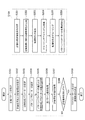
まず、本発明の第1実施形態に係るマスクパターンおよび露光条件の決定方法について説明する。例えば半導体デバイスなどの製造工程に含まれるリソグラフィー工程では、光源を含む照明光学系によりマスク(原版)に対して光が照射され、マスクに形成されているパターンを、投影光学系を介して感光性の基板(ウエハなど)に転写する露光装置が用いられる。特に本実施形態に係る決定方法は、このような露光装置に用いられるマスクのパターンと、露光条件として特にマスクを照明する際の照明形状(有効光源分布)とを決定(最適化)するものとする。ここで、照明形状とは、照明光学系の瞳面に形成される光強度分布であり、マスクを照明する光の角度分布でもある。図1は、本実施形態に係る決定方法を示すフローチャートである。なお、この決定方法は、例えばプログラムとして、汎用の情報処理装置(コンピューター)に実行させ得る。
(First embodiment)
First, a method for determining a mask pattern and exposure conditions according to the first embodiment of the present invention will be described. For example, in a lithography process included in a manufacturing process of a semiconductor device or the like, a mask (original) is irradiated with light by an illumination optical system including a light source, and a pattern formed on the mask is exposed to light via a projection optical system. An exposure apparatus that transfers to a substrate (wafer or the like) is used. In particular, the determination method according to the present embodiment determines (optimizes) a mask pattern used in such an exposure apparatus and an illumination shape (effective light source distribution) when illuminating the mask, in particular, as an exposure condition. To do. Here, the illumination shape is a light intensity distribution formed on the pupil plane of the illumination optical system, and is also an angular distribution of light that illuminates the mask. FIG. 1 is a flowchart showing a determination method according to this embodiment. This determination method can be executed by a general-purpose information processing device (computer) as a program, for example.
まず、S101では、基板に形成すべきパターン(目標パターン)を設定する。この目標パターンとしては、テストパターンのような規則正しい配列を有するパターンや、メモリーセル以外のデバイスパターンのようにランダムな配置となっているパターンなど、その時々により種々の配列(配置)を取り得る。次に、S102では、投影光学系の像面に形成される仮のパターン(転写パターン)の像を評価するための評価位置、およびこの評価位置での評価項目を設定する。ここで、評価項目は、例えば、仮パターンの像の寸法、デフォーカス特性、仮パターンの像の露光量に対する寸法変化、または、仮パターンの像が規格内に収まる露光量もしくはフォーカスの範囲のうち少なくとも1つを含む。次に、S103では、仮の照明形状を規定するための照明形状パラメーター(第2のパラメーター)を設定する。例えば、照明形状の基本形状(例えば、2重極(ダイポール)形状や4重極(クロスポール)形状など)を特徴づける露光パラメーターを照明形状パラメーターとして設定する。次に、S104では、目標パターンに対応する仮パターンの形状を規定するためのパターンパラメーター(第1のパラメーター)を設定する。具体的には、マスクパターンを複数の多角形で構成し、この多角形を特徴づけるパラメーターをパターンパラメーターとして設定する。この場合、例えば、マスクパターンの形状を複数の多角形の組み合わせで構成される形状と一致させ、これらの複数の多角形のそれぞれの辺の長さをパターンパラメーターとして設定し得る。なお、このS104におけるパターンパラメーターの設定の流れ(S201からS206まで)については後述することとし、一旦、S105以下の流れについて説明する。 First, in S101, a pattern (target pattern) to be formed on the substrate is set. As this target pattern, various arrangements (arrangements) can be taken from time to time, such as a pattern having a regular arrangement such as a test pattern and a pattern having a random arrangement such as a device pattern other than a memory cell. Next, in S102, an evaluation position for evaluating an image of a temporary pattern (transfer pattern) formed on the image plane of the projection optical system and evaluation items at this evaluation position are set. Here, the evaluation items include, for example, the size of the temporary pattern image, the defocus characteristic, the dimensional change with respect to the exposure amount of the temporary pattern image, or the exposure amount or focus range within which the temporary pattern image falls within the standard Including at least one. Next, in S103, an illumination shape parameter (second parameter) for defining a provisional illumination shape is set. For example, an exposure parameter that characterizes a basic shape of the illumination shape (for example, a dipole shape or a quadrupole shape) is set as the illumination shape parameter. Next, in S104, a pattern parameter (first parameter) for defining the shape of the temporary pattern corresponding to the target pattern is set. Specifically, the mask pattern is composed of a plurality of polygons, and parameters characterizing the polygons are set as pattern parameters. In this case, for example, the shape of the mask pattern can be made to coincide with a shape constituted by a combination of a plurality of polygons, and the length of each side of the plurality of polygons can be set as a pattern parameter. The pattern parameter setting flow (S201 to S206) in S104 will be described later, and the flow after S105 will be described once.
次に、S105からS109では、S104で設定したパターンパラメーターと、S103で設定した照明形状パラメーターとからなるパラメーター空間を構成し、このパラメーター空間において、パターンパラメーターおよび照明形状パラメーターを最適化する。ここで、パターンパラメーターと照明形状パラメーターとのそれぞれには、制限範囲があるため、この制限範囲内でパターンパラメーターおよび照明形状パラメーターを最適化する必要がある。まず、S105では、パターンパラメーターの値および照明形状パラメーターの値を仮決定する。本実施形態に係る決定方法では、パターンパラメーターの値および照明形状パラメーターの値を変更しながら最適値に追い込んでいく。したがって、制限範囲内であれば、パターンパラメーターの値および照明形状パラメーターの値として、任意の値を仮決定することが可能である。次に、S106では、S105にて仮決定したパターンパラメーターの値および照明形状パラメーターの値に基づいて、投影光学系の像面に形成される仮パターンの像を取得(算出)する。具体的には、S105で仮決定したパターンパラメーターの値で規定される仮パターンを、S105で仮決定した照明形状パラメーターの値で規定される仮照明形状(仮有効光源分布)で照明したときの仮パターンの像を取得する。次に、S107では、S106にて取得された仮パターンの像について、S102で設定された評価位置での評価項目の値を取得(算出)する。次に、S108では、S107にて取得された、仮パターンの像における評価位置での評価項目の値が、評価基準を満たすかどうかを判断する。なお、評価基準は、目標パターンの精度や露光装置の性能などに応じて、評価項目ごとに予め設定されている。ここで、評価位置での評価項目の値が評価基準を満たすと判定した場合には(YES)、S109に移行する。一方、評価位置での評価項目の値が評価基準を満たさないと判定した場合には(NO)、S105に戻ってパターンパラメーターの値および照明形状パラメーターの値を再度仮決定して、S106、S107およびS108を繰り返す。換言すれば、パターンパラメーターの値および照明形状パラメーターの値を変更して、仮パターンの像における評価位置での評価項目の値が評価基準を満たすまで処理を繰り返す。なお、パターンパラメーターの値および照明形状パラメーターの値を再度仮決定する際には、パターンパラメーターの値と照明形状パラメーターの値との組み合わせにおいて、これまでに仮決定されていない値を仮決定する。このとき、パターンパラメーターの値および照明形状パラメーターの値の両方を変更するのではなく、どちらか一方のみを変更することもある。そして、S109では、まず、S104にて仮決定したパターンパラメーターの値で規定される仮パターンをマスクパターンとして決定する。さらに、S104にて仮決定した照明形状パラメーターの値で規定される仮照明形状を、マスクを照明する際の照明形状(露光条件)として決定する。 Next, in S105 to S109, a parameter space composed of the pattern parameter set in S104 and the illumination shape parameter set in S103 is constructed, and the pattern parameter and the illumination shape parameter are optimized in this parameter space. Here, since each of the pattern parameter and the illumination shape parameter has a limited range, it is necessary to optimize the pattern parameter and the illumination shape parameter within the limited range. First, in S105, the value of the pattern parameter and the value of the illumination shape parameter are provisionally determined. In the determination method according to the present embodiment, the value of the pattern parameter and the value of the illumination shape parameter are changed to the optimum value. Accordingly, any value can be provisionally determined as the value of the pattern parameter and the value of the illumination shape parameter as long as it is within the limit range. Next, in S106, an image of a temporary pattern formed on the image plane of the projection optical system is acquired (calculated) based on the pattern parameter value and the illumination shape parameter value temporarily determined in S105. Specifically, when the temporary pattern defined by the value of the pattern parameter provisionally determined in S105 is illuminated with the provisional illumination shape (temporary effective light source distribution) defined by the value of the illumination shape parameter provisionally determined in S105. An image of a temporary pattern is acquired. Next, in S107, the value of the evaluation item at the evaluation position set in S102 is acquired (calculated) for the temporary pattern image acquired in S106. Next, in S108, it is determined whether or not the value of the evaluation item at the evaluation position in the temporary pattern image obtained in S107 satisfies the evaluation criterion. The evaluation criteria are set in advance for each evaluation item according to the accuracy of the target pattern, the performance of the exposure apparatus, and the like. If it is determined that the value of the evaluation item at the evaluation position satisfies the evaluation criterion (YES), the process proceeds to S109. On the other hand, when it is determined that the value of the evaluation item at the evaluation position does not satisfy the evaluation standard (NO), the process returns to S105, and the pattern parameter value and the illumination shape parameter value are provisionally determined again, and S106, S107 And S108 are repeated. In other words, the value of the pattern parameter and the value of the illumination shape parameter are changed, and the process is repeated until the value of the evaluation item at the evaluation position in the temporary pattern image satisfies the evaluation criterion. When the value of the pattern parameter and the value of the illumination shape parameter are provisionally determined again, a value that has not been provisionally determined so far in the combination of the value of the pattern parameter and the value of the illumination shape parameter is provisionally determined. At this time, instead of changing both the value of the pattern parameter and the value of the illumination shape parameter, only one of them may be changed. In S109, first, the temporary pattern defined by the value of the pattern parameter temporarily determined in S104 is determined as a mask pattern. Furthermore, the temporary illumination shape defined by the value of the illumination shape parameter provisionally determined in S104 is determined as the illumination shape (exposure condition) for illuminating the mask.
次に、本実施形態の特徴としてのS104におけるパターンパラメーターの設定の流れ(S201からS206まで)の説明に先立ち、本実施形態の利点を明確にするために、参考としてS201からS206までの流れを考慮しない場合について説明する。特にここでは、近接効果に関わる結像特性(近隣のマスクパターンが評価位置の像に及ぼす影響)が中心パターンとその他のパターンとのCD(Critical Dimension)差を指標とする場合を想定している。まず、第1比較例として、マスクの全変数を使用する場合について説明する。この第1比較例では、S101で設定される目標パターンは、一例として複数の同一な矩形パターンの配列を有するものとしている。図2は、第1比較例における目標パターンの形状や照明形状を示す概略平面図である。なお、この図2に示す各種条件は、後述する本実施形態における場合(S201からのパターンパラメーターを設定を考慮する場合)にも適用されるものである。図2(a)は、目標パターンの形状を示す概略図である。目標パターンは、X方向に240nm、Y方向に160nmのピッチで、5×5の格子状に複数のパターン要素を有する。このうち1つのパターンは、X幅50nm、Y幅40nmの長方形で構成されている。図2(b)は、パターンパラメーターの設定例を示す概略図である。マスクパターンに対しては、j行i列目の長方形のそれぞれの辺の長さ(X方向およびY方向の長さ)PA(i,j)、PB(i,j){1≦i≦5、1≦j≦5}をパターンパラメーターとして設定する。図2(c)は、マスクを照明する際の照明形状(照明形状の基本形状)を示す概略図である。ここでの照明形状は、図2(c)に示すように2重極形状であり、同一の強度を円周方向に有するとともに、開口角方向にも有している。この照明形状に対して、照明形状の外σにPa、外σと内σとの比Pb、および開口角Pφを照明形状パラメーターとして設定する。図2(d)は、照明形状における偏光方向を示す概略図である。ここでの偏光方向は、X偏光とする。 Next, prior to the description of the pattern parameter setting flow in S104 (from S201 to S206) as a feature of the present embodiment, the flow from S201 to S206 is used as a reference in order to clarify the advantages of this embodiment. The case where it is not considered will be described. In particular, here, it is assumed that the imaging characteristics related to the proximity effect (the influence of the neighboring mask pattern on the image at the evaluation position) uses the CD (Critical Dimension) difference between the central pattern and other patterns as an index. . First, as a first comparative example, a case where all variables of the mask are used will be described. In the first comparative example, the target pattern set in S101 is assumed to have an array of a plurality of identical rectangular patterns as an example. FIG. 2 is a schematic plan view showing the shape of the target pattern and the illumination shape in the first comparative example. It should be noted that the various conditions shown in FIG. 2 are also applied to the case of the present embodiment to be described later (when setting the pattern parameters from S201 is considered). FIG. 2A is a schematic diagram showing the shape of the target pattern. The target pattern has a plurality of pattern elements in a 5 × 5 lattice pattern with a pitch of 240 nm in the X direction and 160 nm in the Y direction. One of these patterns is a rectangle having an X width of 50 nm and a Y width of 40 nm. FIG. 2B is a schematic diagram showing an example of setting pattern parameters. For the mask pattern, the length (length in the X and Y directions) PA (i, j), PB (i, j) {1 ≦ i ≦ 5 1 ≦ j ≦ 5} is set as a pattern parameter. FIG. 2C is a schematic diagram showing an illumination shape (basic shape of the illumination shape) when the mask is illuminated. The illumination shape here is a double pole shape as shown in FIG. 2C, and has the same intensity in the circumferential direction and also in the opening angle direction. For this illumination shape, Pa is set as the outer σ of the illumination shape, the ratio Pb of the outer σ to the inner σ, and the opening angle Pφ are set as the illumination shape parameters. FIG. 2D is a schematic diagram showing the polarization direction in the illumination shape. The polarization direction here is X-polarized light.
また、パターンパラメーターには、上記のとおり、デバイスの特性やマスクの製造性を考慮して制限範囲が設定される。例えば、パターンパラメーターPA、PBが小さすぎると、着目パターンが転写されない。一方、パターンパラメーターPA、PBの値を大きくし過ぎると、隣り合うパターン同士の間隔が狭くなり、所望の解像度が得られなくなる可能性がある。そこで、パターンの寸法、重ね合わせ精度、およびデバイスの許容度などに応じて、パターンパラメーターの上限値および下限値を適切に設定する。同様に、照明形状パラメーターにも、露光装置の性能やリソグラフィー特性を考慮して制限範囲が設定される。照明形状パラメーターは、その形状を規定することが可能であっても、露光装置(照明光学系)がその形状を形成することが不可能であれば、その照明形状パラメーターの値は、実用的ではない。そこで、露光装置が形成可能な範囲内で、照明形状パラメーターの上限値および下限値を設定する。このような条件のもと、以下、図2(b)に示すマスクパターン、および図2(c)に示す照明形状において、露光光の波長を193nm、投影光学系の開口数(NA)を1.35とした場合のマスクパターンおよび照明形状の最適化について考える。 Further, as described above, a limited range is set for the pattern parameter in consideration of device characteristics and mask manufacturability. For example, if the pattern parameters PA and PB are too small, the target pattern is not transferred. On the other hand, if the values of the pattern parameters PA and PB are too large, the interval between adjacent patterns becomes narrow, and the desired resolution may not be obtained. Therefore, the upper limit value and the lower limit value of the pattern parameters are appropriately set according to the pattern dimensions, overlay accuracy, device tolerance, and the like. Similarly, a limit range is set for the illumination shape parameter in consideration of the performance of the exposure apparatus and lithography characteristics. Although the illumination shape parameter can define the shape, if the exposure apparatus (illumination optical system) cannot form the shape, the value of the illumination shape parameter is not practical. Absent. Therefore, the upper limit value and the lower limit value of the illumination shape parameter are set within a range that can be formed by the exposure apparatus. Under these conditions, in the mask pattern shown in FIG. 2B and the illumination shape shown in FIG. 2C, the wavelength of the exposure light is 193 nm, and the numerical aperture (NA) of the projection optical system is 1. Consider the optimization of the mask pattern and illumination shape when.
まず、S102では、目標パターンに対応する仮パターンの像を評価するための評価位置を、図2(b)に示すように、評価位置EP1(i,j)、EP2(i,j){1≦i≦5、1≦j≦5}に設定する。ここで、評価位置EP1、EP2における理想的な寸法(目標値)は、それぞれ50nm、40nmであり、その評価項目は、仮パターンの像寸法と目標寸法との差の二乗平均平方根CD_RMS(nm)に設定する。また、パターンパラメーターPA、PBの制限範囲は、20nm<PA(i,j)<100nm、10nm<PB(i,j)<90nmに設定する。さらに、照明形状パラメーターの制限範囲は、0.7<Pa<0.95、0.5<Pb<0.8、0°<Pφ<150°に設定する。(表1)は、この場合のパターンパラメーターPAの割り当てを示し、一方、(表2)は、パターンパラメーターPBの割り当てを示す表である。このような設定において、パターンパラメーターPA、PBと、照明形状パラメーターとからなるパラメーター空間(PA(i,j),PB(i,j),Pa,Pb,Pφ){1≦i≦5、1≦j≦5}が構成される。 First, in S102, as shown in FIG. 2B, evaluation positions EP1 (i, j), EP2 (i, j) {1 are used to evaluate the temporary pattern image corresponding to the target pattern. ≦ i ≦ 5, 1 ≦ j ≦ 5}. Here, ideal dimensions (target values) at the evaluation positions EP1 and EP2 are 50 nm and 40 nm, respectively, and the evaluation items are the root mean square CD_RMS (nm) of the difference between the image dimension of the temporary pattern and the target dimension. Set to. The limiting ranges of the pattern parameters PA and PB are set to 20 nm <PA (i, j) <100 nm, 10 nm <PB (i, j) <90 nm. Furthermore, the limitation ranges of the illumination shape parameters are set to 0.7 <Pa <0.95, 0.5 <Pb <0.8, and 0 ° <Pφ <150 °. (Table 1) shows the assignment of pattern parameters PA in this case, while (Table 2) shows the assignment of pattern parameters PB. In such a setting, a parameter space (PA (i, j), PB (i, j), Pa, Pb, Pφ) {1 ≦ i ≦ 5, 1 consisting of pattern parameters PA and PB and illumination shape parameters. ≦ j ≦ 5} is configured.

ここで、最適化変数の削減効果を明確にするために、まず、変数の削減を行わずに53個の変数(パターンパラメーターの変数は50個)を独立変数として滑降シンプレックス法を用いて同時に最適化を行った。図3は、この場合の評価項目値の減衰を示すグラフであり、最適化のために行った計算回数(回)に対する評価項目値であるCD_RMS(nm)を示している。特に50variableと表記しているものが、第1比較例に対応している。図3に示される結果からわかるとおり、第1比較例における評価項目値は、800回の計算後でも減衰を続けており、収束までに多大な時間を要する。 Here, in order to clarify the reduction effect of the optimization variable, first, without reducing the variables, 53 variables (50 pattern parameter variables) were used as independent variables and optimized simultaneously using the downhill simplex method. Made. FIG. 3 is a graph showing attenuation of the evaluation item value in this case, and shows CD_RMS (nm) that is the evaluation item value with respect to the number of calculations (times) performed for optimization. In particular, what is written as 50 variable corresponds to the first comparative example. As can be seen from the results shown in FIG. 3, the evaluation item values in the first comparative example continue to attenuate even after 800 calculations, and it takes a long time to converge.
さらに、第2比較例として、目標パターンにおける対称性を考慮して変数を使用する場合について説明する。一般的に最適化計算では、最適化変数を少なくすれば、収束が早くなる傾向が知られている。そこで、ここでは、参考として第1比較例と同様にS201からS206までの流れを考慮せず、パターンの物理的形状の対称性の情報を用いて変数の削減を行う場合について考える。このとき、パターンパラメーターの削減策として、隣接する配置図形の繰り返しやミラー反転などの対称性を用いて変数を少なくすることが考えられる。例えば、図2(a)に示すようなパターン(群)のパターンパラメーターは、対称性があるパターンに関しては、以下の式(1)〜(4)に示されるように共通の変数とすることで削減することができる。
PA(1,j)=PA(5,j) (1)
PA(2,j)=PA(4,j) (2)
PA(i,1)=PA(i,5) (3)
PA(i,2)=PA(i,4) (4)
Furthermore, as a second comparative example, a case where variables are used in consideration of symmetry in the target pattern will be described. In general, it is known that the optimization calculation tends to converge faster if the number of optimization variables is reduced. Therefore, here, as a reference, let us consider a case where variables are reduced using information on the symmetry of the physical shape of the pattern without considering the flow from S201 to S206 as in the first comparative example. At this time, as a measure for reducing the pattern parameter, it is conceivable to reduce the number of variables by using symmetry such as repetition of adjacent arranged figures and mirror inversion. For example, the pattern parameter of the pattern (group) as shown in FIG. 2 (a) can be set to a common variable as shown in the following formulas (1) to (4) for a symmetric pattern. Can be reduced.
PA (1, j) = PA (5, j) (1)
PA (2, j) = PA (4, j) (2)
PA (i, 1) = PA (i, 5) (3)
PA (i, 2) = PA (i, 4) (4)
ここで、(表3)は、このように共通化した変数を用いた場合のパターンパラメーターPAの割り当てを示し、一方、(表4)は、パターンパラメーターPBの割り当てを示す表である。(表3)および(表4)において、同じ変数名を有するパターンパラメーターは、同一の数値となる。これらの表からわかるとおり、この場合のパターンパラメーターは、18個となり、照明形状パラメーターの3個と合わせても21個の変数となる。そして、これら21個の変数(パターンパラメーターの変数は18個)を独立変数として滑降シンプレックス法を用いて最適化を行った。この場合の評価項目値の減衰は、図3に示すグラフ中の18variableと表記しているものが該当する。また、このときのパターンパラメーターPAの決定値を(表5)に、パターンパラメーターPBの決定値を(表6)に示す。さらに、このときの照明形状パラメーターの決定値としては、Paが0.904となり、Pbが0.637となり、さらにPφが53°となる。 Here, (Table 3) shows the assignment of the pattern parameter PA when the variables thus shared are used, while (Table 4) shows the assignment of the pattern parameter PB. In (Table 3) and (Table 4), pattern parameters having the same variable name have the same numerical value. As can be seen from these tables, there are 18 pattern parameters in this case, and 21 variables are combined with the three illumination shape parameters. These 21 variables (18 pattern parameter variables) were used as independent variables for optimization using the downhill simplex method. The attenuation of the evaluation item value in this case corresponds to what is described as 18 variable in the graph shown in FIG. The determined values of the pattern parameter PA at this time are shown in (Table 5), and the determined values of the pattern parameter PB are shown in (Table 6). Further, as the determined value of the illumination shape parameter at this time, Pa is 0.904, Pb is 0.637, and Pφ is 53 °.
この第2比較例では、図3に示すように、第1比較例でのパターンパラメーターをすべて独立変数とした場合よりも、最適化の収束が早くなる。参考として、(表7)に、第1比較例および第2比較例における最適化の計算回数とCD_RMS(nm)の値とを示す。 In the second comparative example, as shown in FIG. 3, the convergence of the optimization is faster than when the pattern parameters in the first comparative example are all independent variables. For reference, (Table 7) shows the number of optimization calculations and the value of CD_RMS (nm) in the first comparative example and the second comparative example.
このように、例えばテストパターンのような規則正しい配列を有するパターンに関しては、ミラー反転などの対称性を用いて、独立したパターンパラメーターを半分以下に削減することができる。しかしながら、第2比較例に示したような対称性を用いた変数の圧縮では、実際には(表3)および(表4)に掲げた18個以下にすることは難しい。また、テストパターンではなく、例えば、メモリーセル以外のデバイスパターンのようにランダムな配置となっているパターンの場合には、繰り返しや対称性のあるパターン群が少ないため、この方法でさらに効率的な変数の圧縮を行うのは難しい。すなわち、このような変数の圧縮は、パターン図形の対称性を考慮するだけでは、十分であるとはいえない。そこで、本実施形態では、以下に示すように、パターン図形の対称性の抽出に依存せずに最適化の変数を少なくする。 As described above, for a pattern having a regular arrangement such as a test pattern, the independent pattern parameter can be reduced to half or less by using symmetry such as mirror inversion. However, in the compression of variables using symmetry as shown in the second comparative example, it is actually difficult to reduce the number to 18 or less listed in (Table 3) and (Table 4). In addition, in the case of a pattern which is not a test pattern but a random arrangement such as a device pattern other than a memory cell, for example, there are few repetitive and symmetric patterns, so this method is more efficient. It is difficult to compress variables. In other words, such variable compression is not sufficient only by considering the symmetry of the pattern figure. Therefore, in this embodiment, as will be described below, the number of optimization variables is reduced without depending on the extraction of the symmetry of the pattern figure.
まず、図1のS201では、投影光学系の像面に形成される転写パターンの近接効果に関わる結像特性を評価するための評価位置(第2の評価位置)を設定する。ここでは、図2(b)に示す評価位置EP1、EP2と同じ場所を、近接効果の評価位置として取り扱う。さらに、パターンパラメーターPA、PBがポリゴン図形の1辺なので、辺の両端の幅を評価対象とする。なお、パターンパラメーターがポリゴン図形のエッジ位置である場合には、像のシフト成分を評価対象とすることもできる。 First, in S201 of FIG. 1, an evaluation position (second evaluation position) for evaluating the imaging characteristics related to the proximity effect of the transfer pattern formed on the image plane of the projection optical system is set. Here, the same locations as the evaluation positions EP1 and EP2 shown in FIG. 2B are treated as the proximity effect evaluation positions. Furthermore, since the pattern parameters PA and PB are one side of the polygon figure, the widths at both ends of the side are evaluated. When the pattern parameter is the edge position of the polygon figure, the shift component of the image can also be the evaluation target.
次に、S202では、照明形状パラメーターや、評価位置での結像特性を用いて、近接効果に関わる結像特性を定義する。結像特性としては、例えば、ある照明での転写パターンのうちの着目パターンと参照パターン(中心パターン、図2(a)では3行3列目のパターン要素)と像の寸法差(CD差)が指標となり得る。または、2つの照明(第1の照明および第2の照明)での同一評価位置でのCD差なども指標となり得る。このように、照明形状に関連して変化する結像特性が代表的な近接効果の指標となり得るが、指標は、これらに限定されるものではない。特に本実施形態では、照明形状パラメーターとして、Pa=0.91、Pb=0.73、Pφ=30°と設定し、近接効果の各評価位置のCD値CD_EP1、CD_EP2を算出する。そして、式(5)および式(6)で得られるΔEP1、ΔEP2を近接効果にかかわる結像特性と定義する。
ΔEP1(i,j)=CD_EP1(i,j)−CD_EP1(3,3) (5)
ΔEP2(i,j)=CD_EP2(i,j)−CD_EP2(3,3) (6)
なお、一般的な結像特性の定義では、本実施形態で用いる照明形状パラメーターの設定値に限定しないが、最適化の際に設定範囲内となることが望ましい。
Next, in S202, an imaging characteristic related to the proximity effect is defined using the illumination shape parameter and the imaging characteristic at the evaluation position. As the imaging characteristics, for example, the pattern of interest and the reference pattern (center pattern, pattern element in the third row and third column in FIG. 2A) of the transfer pattern in a certain illumination, and the dimensional difference (CD difference) of the image Can be an indicator. Alternatively, a CD difference at the same evaluation position in two illuminations (first illumination and second illumination) can be used as an index. As described above, the imaging characteristics that change in relation to the illumination shape can be a representative index of the proximity effect, but the index is not limited thereto. In particular, in this embodiment, Pa = 0.91, Pb = 0.73, and Pφ = 30 ° are set as illumination shape parameters, and the CD values CD_EP1 and CD_EP2 at the respective evaluation positions of the proximity effect are calculated. Then, ΔEP1 and ΔEP2 obtained by Expression (5) and Expression (6) are defined as imaging characteristics related to the proximity effect.
ΔEP1 (i, j) = CD_EP1 (i, j) −CD_EP1 (3,3) (5)
ΔEP2 (i, j) = CD_EP2 (i, j) −CD_EP2 (3,3) (6)
Note that the general definition of imaging characteristics is not limited to the setting value of the illumination shape parameter used in the present embodiment, but it is desirable that it is within the setting range during optimization.
次に、S203では、近接効果のすべての評価位置での結像特性の値を、式(5)および式(6)で表される定義式に基づいて取得(算出)する。式(5)で表される定義式に基づいて取得された結像特性ΔEP1の計算結果を(表8)に、式(6)で表される定義式に基づいて取得された結像特性ΔEP2の計算結果を(表9)に示す。 Next, in S203, the values of the imaging characteristics at all the evaluation positions of the proximity effect are acquired (calculated) based on the definition formulas expressed by Expression (5) and Expression (6). The calculation result of the imaging characteristic ΔEP1 acquired based on the definition expression represented by the expression (5) is shown in (Table 8), and the imaging characteristic ΔEP2 acquired based on the definition expression represented by the expression (6). The calculation results are shown in (Table 9).
次に、S204では、S203にて取得された結像特性を複数のグループにグルーピングするためのアルゴリズムを定義する。ここで定義されるものは、具体的には同一グループに入る結像特性の範囲である。まず、グルーピングのグループ数nを設定する。このとき、グループ数nは、予め数値を決定し、これを直接的に入力するものとしてもよいし、同一グループに入る結像特性の数値範囲を規定しておき、実際の結像特性からグループ数を算出し、決定してもよい。ここでは、グループ数nを8とし、結像特性をΔEP1に対して4グループ、ΔEP2に対して4グループの合計8グループにグルーピングするためのアルゴリズムを定義するものとする。さらに、ここで設定されるグループ数nは、最適化で用いるパターンパラメーターの独立変数の数に等しいものとしている。グルーピングは、結像特性の差が大きい程パターンパラメーターの最適値が異なると仮定すると、同一グループ内では結像特性のばらつきが小さい方が望ましい。このことから、結像特性のグループごとの基準値とそれぞれの結像特性との差の二乗和が最小となるように、グループごとの基準値を算出する。具体的には、ΔEP1に対して4グループに分ける場合には、グループの基準値をX(k){k=1,2,3,4}とし、式(7)のExが最小になるようなX(k)の値を算出する。同様に、ΔEP2に対して4グループに分ける場合には、グループの基準値をY(k){k=1,2,3,4}とし、式(8)のEyが最小になるようなY(k)の値を算出する。 Next, in S204, an algorithm for grouping the imaging characteristics acquired in S203 into a plurality of groups is defined. Specifically, what is defined here is a range of imaging characteristics that fall within the same group. First, the number of grouping groups n is set. At this time, the number of groups n may be determined in advance and input directly, or a numerical range of imaging characteristics that fall within the same group is defined, and the group number is determined from the actual imaging characteristics. A number may be calculated and determined. Here, the number n of groups is set to 8, and an algorithm for grouping the imaging characteristics into a total of 8 groups of 4 groups for ΔEP1 and 4 groups for ΔEP2 is defined. Furthermore, the number of groups n set here is assumed to be equal to the number of independent variables of pattern parameters used in optimization. Assuming that the optimum value of the pattern parameter is different as the difference in imaging characteristics is larger, it is desirable that the variation in imaging characteristics is smaller within the same group. Therefore, as the sum of squares of the difference between the reference value and the respective imaging properties of each group of the imaging characteristics is minimized, and calculates the reference value for each group. Specifically, when ΔEP1 is divided into four groups, the group reference value is set to X (k) {k = 1, 2, 3, 4}, and Ex in Expression (7) is minimized. A value of X (k) is calculated. Similarly, when ΔEP2 is divided into four groups, the group reference value is Y (k) {k = 1, 2, 3, 4}, and Y in which Ey in Equation (8) is minimized. The value of (k) is calculated.
ここで取得されたX(k)、Y(k)の値を、(表10)に示す。X(k)を基準値にもつグループをGX(k)とし、一方、Y(k)を基準値にもつグループをGY(k)とすると、(表11)に示すような範囲で分類したことと同じになる。各基準値は、各グループにおける平均値となっている。各グループの範囲の境界値は、隣りのグループの基準値との加算平均値となっている。例えば、GX(2)の下限値は、X(1)とX(2)の加算平均値となっており、GX(2)の上限値は、X(2)とX(3)の加算平均値となっている。なお、GX(1)の下限値とGY(1)の下限値は無限小、GX(4)の上限値とGY(4)の上限値は無限大となっている。 The values of X (k) and Y (k) acquired here are shown in (Table 10). When a group having X (k) as a reference value is GX (k), and a group having Y (k) as a reference value is GY (k), classification is made in the range shown in (Table 11). Will be the same. Each reference value is an average value in each group. The boundary value of the range of each group is an addition average value with the reference value of the adjacent group. For example, the lower limit value of GX (2) is the addition average value of X (1) and X (2), and the upper limit value of GX (2) is the addition average of X (2) and X (3). It is a value. The lower limit value of GX (1) and the lower limit value of GY (1) are infinitesimal, and the upper limit value of GX (4) and the upper limit value of GY (4) are infinite.
次に、S205では、S203にて取得された結像特性にS204の内容を適用し、実際の結像特性のグルーピングを行う。具体的には、X(k)およびY(k)の値がグループの平均値になるようなグルーピングを行う。(表8)に示す結像特性ΔEP1に対して実際にグルーピングを行ったものを(表12)に、(表9)に示す結像特性ΔEP2に対して実際にグルーピングを行ったものを(表13)に示す。これらの表からわかるとおり、1つのグループ内を同一パラメーターとすると、50個のパターンパラメーターは、合計8個のパラメーターに圧縮される。 Next, in S205, the contents of S204 are applied to the imaging characteristics acquired in S203, and the actual imaging characteristics are grouped. Specifically, grouping is performed such that the values of X (k) and Y (k) become the average value of the group. (Table 8) shows the actual grouping for the imaging characteristic ΔEP1 shown in (Table 8), and (Table 9) shows the actual grouping for the imaging characteristic ΔEP2 shown in (Table 9). 13). As can be seen from these tables, assuming that one group has the same parameters, 50 pattern parameters are compressed into a total of 8 parameters.
なお、ここでは、グループの基準値X(k)、Y(k)を変数に取ったが、これに限定されるものではない。例えば、式(9)および式(10)に示すようにDxおよびDyを定義し、等差数列的に、式(11)および式(12)に示すX(k)およびY(k)と基準値を設定してもよい。
Dx={Max(ΔEP1)−Min(ΔEP1)}/4 (9)
Dy={Max(ΔEP2)−Min(ΔEP2)}/4 (10)
X(k)=(k−1)×Dx+Min(ΔEP1)+Dx/2 (11)
Y(k)=(k−1)×Dy+Min(ΔEP2)+Dy/2 (12)
Here, the group reference values X (k) and Y (k) are taken as variables , but the present invention is not limited to this. For example, Dx and Dy are defined as shown in Equation (9) and Equation (10), and X (k) and Y (k) and criteria shown in Equation (11) and Equation (12) are defined as an arithmetic progression. A value may be set.
Dx = {Max (ΔEP1) −Min (ΔEP1)} / 4 (9)
Dy = {Max (ΔEP2) −Min (ΔEP2)} / 4 (10)
X (k) = (k−1) × Dx + Min (ΔEP1) + Dx / 2 (11)
Y (k) = (k−1) × Dy + Min (ΔEP2) + Dy / 2 (12)
そして、S206では、同一のグループにグルーピングされた評価位置に相当するパターンパラメーターが従属変数(すなわち1つにまとめられた変数)になるものとして、パターンパラメーターを割り当てる。その後、図1のS105に移行する。 In S206, the pattern parameter is assigned on the assumption that the pattern parameter corresponding to the evaluation position grouped into the same group becomes a dependent variable (that is, a variable grouped into one). Thereafter, the process proceeds to S105 in FIG.
図4は、図3に対応した、本実施形態における8個の独立したパターンパラメーターと3個の照明形状パラメーターとを用いた場合の評価項目値(結像特性の指標値)の減衰を示すグラフである。ここで、8variableと表記しているものが、本実施形態に係る結果であり、参考として第2比較例の結果(18variable)も併記している。また、このときのパターンパラメーターPAの決定値を(表14)に、パターンパラメーターPBの決定値を(表15)に示す。さらに、このときの照明形状パラメーターの決定値としては、Paが0.916となり、Pbが0.647となり、さらにPφが102°となる。 FIG. 4 is a graph corresponding to FIG. 3 and showing attenuation of evaluation item values (index values of imaging characteristics) when using eight independent pattern parameters and three illumination shape parameters in the present embodiment. It is. Here, what is described as 8 variable is the result according to the present embodiment, and the result of the second comparative example (18 variable) is also shown as a reference. The determined values of the pattern parameter PA at this time are shown in (Table 14), and the determined values of the pattern parameter PB are shown in (Table 15). Further, as the determined value of the illumination shape parameter at this time, Pa is 0.916, Pb is 0.647, and Pφ is 102 °.
本実施形態では、図4に示すように、第2比較例での18個の独立したパターンパラメーターを用いた場合よりも、最適化の収束が早くなる。参考として、(表16)に、第2比較例および本実施形態における最適化の計算回数とCD_RMS(nm)の値とを示す。 In the present embodiment, as shown in FIG. 4, the convergence of the optimization is faster than in the case of using 18 independent pattern parameters in the second comparative example. For reference, (Table 16) shows the number of optimization calculations and the value of CD_RMS (nm) in the second comparative example and this embodiment.
このように、本実施形態に係る決定方法は、まず、パターンを十分な精度で基板に形成することが可能なマスクパターンと、マスクを照明する際の照明形状との両方を同時に最適化(決定)することができる。さらに、この決定方法は、着目パターンと参照パターンとの像のCD差を近接効果に関わる結像特性の指標と定義し、この指標に基づいてグルーピングしたパターンパラメーターを用いることで、従来よりも少ない計算回数で効率的に最適解を導くことができる。例えば、従来の対称性を用いた変数の圧縮では、その圧縮数に限界があるが、本実施形態では、対称性に依存せずに効果的に最適化の独立変数を削減できる。そして、この決定方法は、メモリーセル以外のデバイスパターンのようにランダムな配置のパターン(比較的図形数が多いパターン)で、最初のパターンパラメーターの数が多い場合の最適化において、収束時間を短縮させる上で特に有利となり得る。 As described above, the determination method according to the present embodiment first optimizes (determines simultaneously both the mask pattern capable of forming the pattern on the substrate with sufficient accuracy and the illumination shape when the mask is illuminated. )can do. Further, in this determination method, the CD difference between the image of the target pattern and the reference pattern is defined as an index of imaging characteristics related to the proximity effect, and pattern parameters grouped based on this index are used. An optimal solution can be efficiently derived by the number of calculations. For example, in the conventional compression of variables using symmetry, the number of compression is limited, but in this embodiment, the independent variable for optimization can be effectively reduced without depending on symmetry. This determination method reduces the convergence time in optimization when the number of first pattern parameters is large in a pattern with a random arrangement (a pattern with a relatively large number of figures) like a device pattern other than memory cells. Can be particularly advantageous.
以上のように、本実施形態によれば、パターンを高精度で基板上に形成することが可能なマスクパターンおよび露光条件を効率的に決定し得る方法、および、このような処理を情報処理装置に実行させるプログラムを提供することができる。 As described above, according to the present embodiment, a method capable of efficiently determining a mask pattern and an exposure condition capable of forming a pattern on a substrate with high accuracy, and such processing as an information processing apparatus. A program to be executed can be provided.
(第2実施形態)
次に、本発明の第2実施形態に係るマスクパターンおよび露光条件の決定方法について説明する。第1実施形態では、近接効果に関わる結像特性が、中心パターン(参照パターン)と、評価値を計算するために着目しているその他の着目パターンとの像のCD差である場合を想定した。これに対して、本実施形態では、その結像特性を別の定義とする点が第1実施形態と異なり、特に、ここでは、近接効果に関わる結像特性が2つの照明(第1の照明および第2の照明)のCD差である場合を想定する。そして、第1実施形態と同様に、図2(b)に示すマスクパターンと図2(c)に示す照明形状とを用い、かつ近接効果の評価位置も同様として目標寸法に近づくようなパラメーターの決定を行う。以下、第1実施形態の説明にて使用した図1の各ステップを参照して決定方法の手順を説明する。なお、以下の説明で触れられていない図1の残りのステップについては、第1実施形態と同一である。
(Second Embodiment)
Next, a mask pattern and exposure condition determination method according to the second embodiment of the present invention will be described. In the first embodiment, it is assumed that the imaging characteristic related to the proximity effect is a CD difference between an image of the center pattern (reference pattern) and another target pattern focused on for calculating an evaluation value. . On the other hand, the present embodiment is different from the first embodiment in that the imaging characteristic is defined as another definition. In particular, here, the imaging characteristic related to the proximity effect has two illuminations (first illumination). And the second illumination) CD difference. Similarly to the first embodiment, the mask pattern shown in FIG. 2B and the illumination shape shown in FIG. 2C are used, and the evaluation position of the proximity effect is similarly set to a parameter that approaches the target dimension. Make a decision. Hereinafter, the procedure of the determination method will be described with reference to each step of FIG. 1 used in the description of the first embodiment. The remaining steps in FIG. 1 that are not mentioned in the following description are the same as those in the first embodiment.
まず、照明形状パラメーターが、Pa=0.91、Pb=0.73、Pφ=30°のときの近接効果の評価位置EP1(i,j)のCD値をCD1_EP1(i,j)、近接効果の評価位置EP2(i,j)のCD値をCD1_EP2(i,j)とする。一方、照明形状パラメーターが、Pa=0.95、Pb=0.73、Pφ=30°のときの近接効果の評価位置EP1(i,j)のCD値をCD2_EP1(i,j)、近接効果の評価位置EP2(i,j)のCD値をCD2_EP2(i,j)とする。この場合、図1のS202では、近接効果に関わる結像特性ΔEP1、ΔEP2を、以下の式(13)および式(14)のように定義する。
ΔEP1(i,j)=CD2_EP1(i,j)−CD1_EP1(i,j)
(13)
ΔEP2(i,j)=CD2_EP2(i,j)−CD1_EP2(i,j)
(14)
First, when the illumination shape parameters are Pa = 0.91, Pb = 0.73, and Pφ = 30 °, the CD value of the proximity effect evaluation position EP1 (i, j) is CD1_EP1 (i, j), and the proximity effect. Let CD1_EP2 (i, j) be the CD value of the evaluation position EP2 (i, j). On the other hand, when the illumination shape parameters are Pa = 0.95, Pb = 0.73, and Pφ = 30 °, the CD value of the proximity effect evaluation position EP1 (i, j) is CD2_EP1 (i, j), and the proximity effect. Let CD2_EP2 (i, j) be the CD value of the evaluation position EP2 (i, j). In this case, in S202 of FIG. 1, the imaging characteristics ΔEP1 and ΔEP2 related to the proximity effect are defined as in the following expressions (13) and (14).
ΔEP1 (i, j) = CD2_EP1 (i, j) −CD1_EP1 (i, j)
(13)
ΔEP2 (i, j) = CD2_EP2 (i, j) −CD1_EP2 (i, j)
(14)
次に、S203では、近接効果のすべての評価位置での結像特性を、式(13)および式(14)で表される定義式に基づいて取得(算出)する。式(13)で表される定義式に基づいて取得された結像特性ΔEP1の結果を(表17)に、式(14)で表される定義式に基づいて取得された結像特性ΔEP2の結果を(表18)に示す。
Next, in S203, the imaging characteristics at all evaluation positions of the proximity effect are acquired (calculated) based on the definition formulas expressed by the formulas (13) and (14). The result of the imaging characteristic ΔEP1 acquired based on the definition expression expressed by the expression (13) is shown in (Table 17 ), and the imaging characteristic ΔEP2 acquired based on the definition expression expressed by the expression (14) is calculated. The results are shown in (Table 18 ).
次に、S204では、S203にて取得された結像特性を複数のグループにグルーピングするためのアルゴリズムを定義する。ここでは、グループ数nを10とし、結像特性をΔEP1に対して5グループ、ΔEP2に対して5グループの合計10グループにグルーピングするためのアルゴリズムを定義するものとする。そして、ΔEP1に対して5グループに分ける場合には、グループの基準値をX(k){k=1,2,3,4,5}とし、式(7)のExが最小になるようなX(k)の値を算出する。同様に、ΔEP2に対して5グループに分ける場合には、グループの基準値をY(k){k=1,2,3,4,5}とし、式(8)のEyが最小になるようなY(k)の値を算出する。すなわち、グルーピングのアルゴリズムは、第1実施形態と同一としている。ここで取得されたX(k)、Y(k)の値を、(表19)に示す。X(k)を基準値とするグループをGX(k)とし、一方、Y(k)を基準値とするグループをGY(k)とすると、(表20)に示すような範囲で分類したことと同じになる。各基準値は、各グループにおける平均値となっている。各グループの範囲の境界値は、隣りのグループの基準値との加算平均値となっている。第1実施形態と同様である。 Next, in S204, an algorithm for grouping the imaging characteristics acquired in S203 into a plurality of groups is defined. Here, it is assumed that the number n of groups is 10, and an algorithm for grouping the imaging characteristics into a total of 10 groups of 5 groups for ΔEP1 and 5 groups for ΔEP2. When ΔEP1 is divided into 5 groups, the group reference value is set to X (k) {k = 1, 2, 3, 4, 5}, and Ex in Expression (7) is minimized. The value of X (k) is calculated. Similarly, when ΔEP2 is divided into five groups, the reference value of the group is Y (k) {k = 1, 2, 3, 4, 5}, and Ey in equation (8) is minimized. The value of Y (k) is calculated. That is, the grouping algorithm is the same as in the first embodiment. The values of X (k) and Y (k) acquired here are shown in (Table 19). When a group having X (k) as a reference value is GX (k), and a group having Y (k) as a reference value is GY (k), classification is made in the range shown in (Table 20). Will be the same. Each reference value is an average value in each group. The boundary value of the range of each group is an addition average value with the reference value of the adjacent group. This is the same as in the first embodiment.
次に、S205では、S203にて取得された結像特性にS204の内容を適用し、実際の結像特性のグルーピングを行う。本実施形態においても、X(k)およびY(k)の値がグループの平均値になるようなグルーピングを行う。(表17)に示す結像特性ΔEP1に対して実際にグルーピングを行ったものを、(表21)に、(表18)に示す結像特性ΔEP2に対して実際にグルーピングを行ったものを(表22)に示す。これらの表からわかるとおり、1つのグループ内を同一パラメーターとすると、50個のパターンパラメーターは、合計10個のパラメーターに圧縮される。 Next, in S205, the contents of S204 are applied to the imaging characteristics acquired in S203, and the actual imaging characteristics are grouped. Also in the present embodiment, grouping is performed such that the values of X (k) and Y (k) become the average value of the group. What is actually grouped for the imaging characteristic ΔEP1 shown in (Table 17), what is actually grouped for the imaging characteristic ΔEP2 shown in (Table 18), (Table 21) Table 22) shows. As can be seen from these tables, assuming that one group has the same parameters, 50 pattern parameters are compressed into a total of 10 parameters.
そして、S206では、同一グループに分類された評価位置に相当するパターンパラメーターを従属変数としてパターンパラメーターを割り当て、その後、S105に移行することについては、第1実施形態と同様である。 In S206, the pattern parameter corresponding to the evaluation position classified into the same group is assigned as a dependent variable, and thereafter, the process proceeds to S105, which is the same as in the first embodiment.
図5は、図4に対応した、本実施形態における10個の独立したパターンパラメーターと3個の照明形状パラメーターとを用いた場合の評価項目値(結像特性の指標値)の減衰を示すグラフである。ここで、10variableと表記しているものが本実施形態に係る結果であり、参考として第2比較例の結果(18variable)も併記している。また、このときのパターンパラメーターPAの決定値を(表23)に、パターンパラメーターPBの決定値を(表24)に示す。さらに、このときの照明形状パラメーターの決定値としては、Paが0.873となり、Pbが0.728となり、さらにPφが74°となる。 FIG. 5 is a graph corresponding to FIG. 4 and showing attenuation of evaluation item values (index values of imaging characteristics) when 10 independent pattern parameters and three illumination shape parameters in the present embodiment are used. It is. Here, what is described as 10 variable is the result according to the present embodiment, and the result of the second comparative example (18 variable) is also shown for reference. The determined values of the pattern parameter PA at this time are shown in (Table 23), and the determined values of the pattern parameter PB are shown in (Table 24). Further, as the determined values of the illumination shape parameters at this time, Pa is 0.873, Pb is 0.728, and Pφ is 74 °.
本実施形態でも、図5に示すように、第2比較例での18個の独立したパターンパラメーターを用いた場合よりも、最適化の収束が早くなる。参考として、(表25)に、第2比較例および本実施形態における最適化の計算回数とCD_RMS(nm)の値とを示す。 Also in this embodiment, as shown in FIG. 5, the convergence of the optimization is faster than in the case of using 18 independent pattern parameters in the second comparative example. As a reference, (Table 25) shows the number of optimization calculations and the value of CD_RMS (nm) in the second comparative example and this embodiment.
このように、本実施形態に係る決定方法では、2つの照明のCD差を近接効果に関わる結像特性の指標と定義し、この指標によりグルーピングしたパターンパラメーターを用いることで、第1実施形態と同様の効果を奏する。 As described above, in the determination method according to the present embodiment, the CD difference between the two illuminations is defined as an index of the imaging characteristic related to the proximity effect, and the pattern parameter grouped by this index is used. The same effect is produced.
(第3実施形態)
次に、本発明の第3実施形態に係るマスクパターンおよび露光条件の決定方法について説明する。上記各実施形態では、独立した最適化変数をグルーピングにより減少させることで、最適化の収束を早める。このとき、変数の自由度をさらに上げることができれば、最終的な解の到達点をさらに良好にする(最良解を取得する)ことができる。そこで、本実施形態では、最適化の収束を早めるとともに、図1に示す上記各実施形態に係る決定方法に新たなステップを追加することで、到達解を最良解に近づける。
(Third embodiment)
Next, a method for determining a mask pattern and exposure conditions according to the third embodiment of the present invention will be described. In each of the above embodiments, optimization optimization is accelerated by reducing independent optimization variables by grouping. At this time, if the degree of freedom of the variables can be further increased, the final solution reaching point can be further improved (the best solution is obtained). Therefore, in this embodiment, the convergence of optimization is accelerated, and a new step is added to the determination method according to each of the embodiments shown in FIG.
図6は、図1に対応した、本実施形態に係る決定方法の手順を示すフローチャートである。図6において、図1に示すステップと同一ステップについては同一のステップ番号を付し、説明を省略する。ここでは、特に、S102で設定された評価位置での評価項目を取得する工程(S107)と、この評価項目の値が評価基準を満たすかどうかを判断する工程(S108)との間に、S301として、規定の計算回数を経過したかどうかを判断する工程を含む。さらに、S301にて計算回数が規定数を超えていないと判定した場合には(YES)、S302として、グループ数nを変更する(増やす)工程を含む。この場合、まず、最初のグループ数nを予め設定してパターンパラメーターと照明形状パラメーターとの最適化を開始する。そして、計算回数が規定数(例えば20回)を超えていない場合、S302に移行し、グループ数を増やす。このS302では、例えば、1回目は2個、2回目は4個、3回目は8個、4回目は16個というように徐々に増加させ、それ以降、同様に最適化を続ける。ここで、近接効果に関わる結像特性を求める際の照明形状パラメーターは、直前の最適化で得られたものを適用するものとする。さらに、パターンパラメーターも、最適解で得られたものを初期値として適用する。このように、本実施形態によれば、段階的にパターンパラメーターの数が増えるため、最適化の中でそれぞれの最適化の初期値が最良解に近い値を使用(入力)できる。したがって、最適化の収束がさらに早まり、かつ、最終的には全変数を独立パラメーターにすることでき、到達解も最良解となる。 FIG. 6 is a flowchart showing the procedure of the determination method according to the present embodiment, corresponding to FIG. In FIG. 6, the same steps as those shown in FIG. 1 are denoted by the same step numbers, and description thereof is omitted. Here, in particular, between the step (S107) of obtaining the evaluation item at the evaluation position set in S102 and the step (S108) of determining whether or not the value of this evaluation item satisfies the evaluation criteria. And a step of determining whether or not the prescribed number of calculations has passed. Furthermore, when it is determined in S301 that the number of calculations does not exceed the prescribed number (YES), a step of changing (increasing) the number of groups n is included as S302. In this case, first, the initial number n of groups is set in advance, and optimization of pattern parameters and illumination shape parameters is started. If the number of calculations does not exceed a specified number (for example, 20 times), the process proceeds to S302 to increase the number of groups. In this step S302, for example, the number of times is gradually increased to 2 for the first time, 4 for the second time, 8 for the third time, 16 for the fourth time, and 16 for the fourth time. Here, as the illumination shape parameter for obtaining the imaging characteristics related to the proximity effect, the one obtained in the last optimization is applied. Furthermore, the pattern parameters obtained by the optimum solution are applied as initial values. As described above, according to the present embodiment, the number of pattern parameters increases step by step, so that the initial value of each optimization can use (input) a value close to the best solution during the optimization. Therefore, the convergence of the optimization is further accelerated, and finally all variables can be made independent parameters, and the reaching solution is also the best solution.
以上、本発明の好ましい実施形態について説明したが、本発明は、これらの実施形態に限定されず、その要旨の範囲内で種々の変形および変更が可能である。 As mentioned above, although preferable embodiment of this invention was described, this invention is not limited to these embodiment, A various deformation | transformation and change are possible within the range of the summary.
EP1 評価位置
EP2 評価位置
PA パターンパラメーター
PB パターンパラメーター
Pa 照明形状パラメーター
Pb 照明形状パラメーター
Pφ 照明形状パラメーター
EP1 Evaluation position EP2 Evaluation position PA Pattern parameter PB Pattern parameter Pa Illumination shape parameter Pb Illumination shape parameter Pφ Illumination shape parameter
Claims (7)
前記投影光学系の像面において前記複数のパターン要素の像を評価するための評価位置、および該評価位置での評価項目を設定するステップと、
前記マスクの複数のパターン要素の形状を規定するための第1のパラメーターを設定するステップと、
前記有効光源分布を規定するための第2のパラメーターを設定するステップと、
前記第1のパラメーターおよび前記第2のパラメーターの値を変更しながら、前記マスクの複数のパターン要素の像の計算と前記評価項目の値の計算とを繰り返し、該繰り返しの計算結果に基づいて前記マスクのパターンおよび前記有効光源分布を決定するステップと、
を含み、
前記第1のパラメーターを設定するステップにおいて、
前記マスクの複数のパターン要素のうち、評価対象となっている各パターン要素について、前記評価対象となっているパターン要素の近隣のパターン要素が前記評価対象となっているパターン要素の前記評価位置の像に及ぼす近接効果を表す指標の値を算出し、
該算出された前記指標の値に基づいて複数のパターン要素のパラメーターをまとめて1つの前記第1のパラメーターとして設定し、
前記近接効果を表す指標は、第1の有効光源分布で前記評価対象となっているパターン要素を照明した場合と前記第1の有効光源分布とは異なる形状の第2の有効光源分布で前記評価対象となっているパターン要素を照明した場合とにおける、前記評価対象となっているパターン要素の像の寸法差である、
ことを特徴とする決定方法。 A pattern of the mask used in an exposure apparatus comprising: an illumination optical system that illuminates the mask using light from a light source; and a projection optical system that projects images of a plurality of pattern elements formed on the mask onto a substrate; A determination method for determining an effective light source distribution formed by the illumination optical system using a computer,
Setting an evaluation position for evaluating images of the plurality of pattern elements on the image plane of the projection optical system, and an evaluation item at the evaluation position;
Setting a first parameter for defining the shape of a plurality of pattern elements of the mask;
Setting a second parameter for defining the effective light source distribution;
While changing the values of the first parameter and the second parameter, the calculation of the image of the plurality of pattern elements of the mask and the calculation of the value of the evaluation item are repeated, and based on the result of the repeated calculation, Determining a mask pattern and the effective light source distribution;
Including
In the step of setting the first parameter,
Of the plurality of pattern elements of the mask, for each pattern element to be evaluated, a pattern element in the vicinity of the pattern element to be evaluated is the evaluation position of the pattern element to be evaluated. Calculate the index value that represents the proximity effect on the image,
Based on the calculated index value, a plurality of pattern element parameters are collectively set as one first parameter ,
The index representing the proximity effect is obtained by evaluating the second effective light source distribution having a shape different from that of the first effective light source distribution when the pattern element to be evaluated is illuminated with the first effective light source distribution. It is a dimensional difference in the image of the pattern element that is the evaluation target when the pattern element that is the target is illuminated .
A determination method characterized by that.
結像特性を定義するステップと、
前記結像特性を評価する第2の評価位置を設定するステップと、
前記結像特性の値を、すべての前記第2の評価位置について算出するステップと、
前記算出された結像特性の値を予め設定されたグループにグルーピングし、複数の前記結像特性の値をまとめて1つのグループにグルーピングするステップと、
前記1つのグループにグルーピングされた結像特性の値に対応する前記第2の評価位置における前記第1のパラメーターをまとめて1つのパラメーターとして設定するステップと、を含む、
ことを特徴とする請求項1記載の決定方法。 Setting the first parameter comprises:
Defining imaging characteristics; and
Setting a second evaluation position for evaluating the imaging characteristics;
Calculating the value of the imaging characteristic for all the second evaluation positions;
Grouping the calculated imaging characteristic values into a preset group, and grouping the imaging characteristic values together into one group; and
Including collectively setting the first parameters at the second evaluation positions corresponding to the imaging characteristic values grouped into the one group as one parameter.
The determination method according to claim 1.
Priority Applications (5)
| Application Number | Priority Date | Filing Date | Title |
|---|---|---|---|
| JP2012257363A JP6095334B2 (en) | 2012-11-26 | 2012-11-26 | Method and program for determining mask pattern and exposure conditions |
| TW102140283A TWI539243B (en) | 2012-11-26 | 2013-11-06 | Method of determining mask pattern and exposure condition, and storage medium |
| CN201310593722.8A CN103838089B (en) | 2012-11-26 | 2013-11-21 | Method of determining mask pattern and exposure condition and computer |
| KR1020130143629A KR101689429B1 (en) | 2012-11-26 | 2013-11-25 | Method of determining mask pattern and exposure condition, storage medium, and computer |
| US14/089,857 US8958059B2 (en) | 2012-11-26 | 2013-11-26 | Method of determining mask pattern and exposure condition, storage medium, and computer |
Applications Claiming Priority (1)
| Application Number | Priority Date | Filing Date | Title |
|---|---|---|---|
| JP2012257363A JP6095334B2 (en) | 2012-11-26 | 2012-11-26 | Method and program for determining mask pattern and exposure conditions |
Publications (3)
| Publication Number | Publication Date |
|---|---|
| JP2014107331A JP2014107331A (en) | 2014-06-09 |
| JP2014107331A5 JP2014107331A5 (en) | 2016-01-21 |
| JP6095334B2 true JP6095334B2 (en) | 2017-03-15 |
Family
ID=50773012
Family Applications (1)
| Application Number | Title | Priority Date | Filing Date |
|---|---|---|---|
| JP2012257363A Active JP6095334B2 (en) | 2012-11-26 | 2012-11-26 | Method and program for determining mask pattern and exposure conditions |
Country Status (5)
| Country | Link |
|---|---|
| US (1) | US8958059B2 (en) |
| JP (1) | JP6095334B2 (en) |
| KR (1) | KR101689429B1 (en) |
| CN (1) | CN103838089B (en) |
| TW (1) | TWI539243B (en) |
Families Citing this family (6)
| Publication number | Priority date | Publication date | Assignee | Title |
|---|---|---|---|---|
| JP5835968B2 (en) * | 2011-07-05 | 2015-12-24 | キヤノン株式会社 | Determination method, program, and exposure method |
| US10025201B2 (en) * | 2014-04-14 | 2018-07-17 | Asml Netherlands B.V. | Flows of optimization for lithographic processes |
| TWI710866B (en) | 2014-05-30 | 2020-11-21 | 日商尼康股份有限公司 | Computer program and computer readable recording medium for lithography step |
| KR102404639B1 (en) | 2015-02-02 | 2022-06-03 | 삼성전자주식회사 | method for exposing a electron beam and substrate manufacturing method including the same |
| US9588446B2 (en) * | 2015-05-29 | 2017-03-07 | Taiwan Semiconductor Manufacturing Co., Ltd. | Calibration apparatus and an adjustment method for a lithography apparatus |
| CN107667315B (en) * | 2015-05-29 | 2021-04-16 | Asml荷兰有限公司 | Lithography simulation using multiple sampling of the angular distribution of source radiation |
Family Cites Families (13)
| Publication number | Priority date | Publication date | Assignee | Title |
|---|---|---|---|---|
| JP3409493B2 (en) * | 1995-03-13 | 2003-05-26 | ソニー株式会社 | Mask pattern correction method and correction device |
| JP2002329658A (en) * | 2001-05-01 | 2002-11-15 | Fujitsu Ltd | Light proximity effect correction method |
| TWI252516B (en) * | 2002-03-12 | 2006-04-01 | Toshiba Corp | Determination method of process parameter and method for determining at least one of process parameter and design rule |
| JP2004077837A (en) * | 2002-08-19 | 2004-03-11 | Sony Corp | Correcting method of design pattern |
| JP2005049403A (en) * | 2003-07-29 | 2005-02-24 | Seiko Epson Corp | Exposure mask, optical proximity correction apparatus, optical proximity correction method, method for manufacturing semiconductor device, and optical proximity correction program |
| JP4351928B2 (en) * | 2004-02-23 | 2009-10-28 | 株式会社東芝 | Mask data correction method, photomask manufacturing method, and mask data correction program |
| JP2007086586A (en) * | 2005-09-26 | 2007-04-05 | Renesas Technology Corp | Method for designing mask pattern and method for manufacturing semiconductor device |
| JP5071785B2 (en) * | 2007-07-13 | 2012-11-14 | 独立行政法人産業技術総合研究所 | Mask pattern forming method |
| JP5404216B2 (en) * | 2009-07-02 | 2014-01-29 | キヤノン株式会社 | Exposure method, exposure apparatus, and device manufacturing method |
| NL2005523A (en) * | 2009-10-28 | 2011-05-02 | Asml Netherlands Bv | Selection of optimum patterns in a design layout based on diffraction signature analysis. |
| US8739079B2 (en) * | 2009-10-30 | 2014-05-27 | Canon Kabushiki Kaisha | Recording medium and determination method |
| JP5686567B2 (en) * | 2010-10-19 | 2015-03-18 | キヤノン株式会社 | Program and method for determining exposure conditions and mask pattern |
| KR101833017B1 (en) * | 2011-02-15 | 2018-04-13 | 삼성전자 주식회사 | Method of manufacturing photomask |
-
2012
- 2012-11-26 JP JP2012257363A patent/JP6095334B2/en active Active
-
2013
- 2013-11-06 TW TW102140283A patent/TWI539243B/en active
- 2013-11-21 CN CN201310593722.8A patent/CN103838089B/en active Active
- 2013-11-25 KR KR1020130143629A patent/KR101689429B1/en active IP Right Grant
- 2013-11-26 US US14/089,857 patent/US8958059B2/en active Active
Also Published As
| Publication number | Publication date |
|---|---|
| TW201421171A (en) | 2014-06-01 |
| US8958059B2 (en) | 2015-02-17 |
| JP2014107331A (en) | 2014-06-09 |
| KR20140067919A (en) | 2014-06-05 |
| US20140146311A1 (en) | 2014-05-29 |
| TWI539243B (en) | 2016-06-21 |
| CN103838089A (en) | 2014-06-04 |
| CN103838089B (en) | 2017-01-18 |
| KR101689429B1 (en) | 2016-12-23 |
Similar Documents
| Publication | Publication Date | Title |
|---|---|---|
| JP6095334B2 (en) | Method and program for determining mask pattern and exposure conditions | |
| US7716628B2 (en) | System, method and program for generating mask data, exposure mask and semiconductor device in consideration of optical proximity effects | |
| US9507253B2 (en) | Mask pattern generating method, recording medium, and information processing apparatus | |
| KR101375376B1 (en) | Recording medium recording program for generating mask data, method for manufacturing mask, and exposure method | |
| US8332784B2 (en) | Semiconductor device | |
| JP4336671B2 (en) | A program for causing a computer to determine exposure parameters, a determination method for determining exposure parameters, an exposure method, and a device manufacturing method. | |
| JP5677356B2 (en) | Generation method of mask pattern | |
| CN113050363A (en) | Method for establishing optical proximity correction model and optical proximity correction method | |
| KR101385832B1 (en) | Program storage medium and method for determining exposure condition and mask pattern | |
| JP5988569B2 (en) | Determination method, determination device, and program | |
| JP3977544B2 (en) | Circuit design method for semiconductor device and program storage medium | |
| JP6039910B2 (en) | Generation method, program, and information processing apparatus | |
| JP4838866B2 (en) | A determination method, an exposure method, and a device manufacturing method for determining an exposure parameter and a reticle pattern. | |
| JP2011233744A (en) | Exposure method and method of manufacturing semiconductor device | |
| US8701053B2 (en) | Decision method, storage medium and information processing apparatus | |
| JP2004126010A (en) | Photomask design method, pattern prediction method, and program | |
| US8832607B2 (en) | Method for making correction map of dose amount, exposure method, and method for manufacturing semiconductor device | |
| JP2012063431A (en) | Position determination method of auxiliary pattern, manufacturing method of photomask, and manufacturing method of semiconductor device | |
| US9152037B2 (en) | Pattern correction method, storage medium, information processing apparatus, method of manufacturing mask, exposure apparatus, and method of manufacturing device | |
| JP2014059362A (en) | Method for preparing mask data, program, information processing device, and mask manufacturing method |
Legal Events
| Date | Code | Title | Description |
|---|---|---|---|
| A521 | Written amendment |
Free format text: JAPANESE INTERMEDIATE CODE: A523 Effective date: 20151126 |
|
| A621 | Written request for application examination |
Free format text: JAPANESE INTERMEDIATE CODE: A621 Effective date: 20151126 |
|
| A977 | Report on retrieval |
Free format text: JAPANESE INTERMEDIATE CODE: A971007 Effective date: 20160819 |
|
| A131 | Notification of reasons for refusal |
Free format text: JAPANESE INTERMEDIATE CODE: A131 Effective date: 20160830 |
|
| A521 | Written amendment |
Free format text: JAPANESE INTERMEDIATE CODE: A523 Effective date: 20161027 |
|
| TRDD | Decision of grant or rejection written | ||
| A01 | Written decision to grant a patent or to grant a registration (utility model) |
Free format text: JAPANESE INTERMEDIATE CODE: A01 Effective date: 20170117 |
|
| A61 | First payment of annual fees (during grant procedure) |
Free format text: JAPANESE INTERMEDIATE CODE: A61 Effective date: 20170214 |
|
| R151 | Written notification of patent or utility model registration |
Ref document number: 6095334 Country of ref document: JP Free format text: JAPANESE INTERMEDIATE CODE: R151 |