JP6095004B2 - Rotating electrical machine control device - Google Patents

Rotating electrical machine control device Download PDF

Info

Publication number
JP6095004B2
JP6095004B2 JP2013165182A JP2013165182A JP6095004B2 JP 6095004 B2 JP6095004 B2 JP 6095004B2 JP 2013165182 A JP2013165182 A JP 2013165182A JP 2013165182 A JP2013165182 A JP 2013165182A JP 6095004 B2 JP6095004 B2 JP 6095004B2
Authority
JP
Japan
Prior art keywords
torque
value
magnetic flux
magnet
calculation unit
Prior art date
Legal status (The legal status is an assumption and is not a legal conclusion. Google has not performed a legal analysis and makes no representation as to the accuracy of the status listed.)
Active
Application number
JP2013165182A
Other languages
Japanese (ja)
Other versions
JP2015035877A (en
JP2015035877A5 (en
Inventor
裕人 今西
裕人 今西
宮崎 英樹
英樹 宮崎
勝洋 星野
勝洋 星野
鈴木 康介
康介 鈴木
安部 元幸
元幸 安部
Current Assignee (The listed assignees may be inaccurate. Google has not performed a legal analysis and makes no representation or warranty as to the accuracy of the list.)
Hitachi Astemo Ltd
Original Assignee
Hitachi Automotive Systems Ltd
Priority date (The priority date is an assumption and is not a legal conclusion. Google has not performed a legal analysis and makes no representation as to the accuracy of the date listed.)
Filing date
Publication date
Application filed by Hitachi Automotive Systems Ltd filed Critical Hitachi Automotive Systems Ltd
Priority to JP2013165182A priority Critical patent/JP6095004B2/en
Priority to PCT/JP2014/063637 priority patent/WO2015019678A1/en
Publication of JP2015035877A publication Critical patent/JP2015035877A/en
Publication of JP2015035877A5 publication Critical patent/JP2015035877A5/ja
Application granted granted Critical
Publication of JP6095004B2 publication Critical patent/JP6095004B2/en
Active legal-status Critical Current
Anticipated expiration legal-status Critical

Links

Images

Classifications

    • HELECTRICITY
    • H02GENERATION; CONVERSION OR DISTRIBUTION OF ELECTRIC POWER
    • H02PCONTROL OR REGULATION OF ELECTRIC MOTORS, ELECTRIC GENERATORS OR DYNAMO-ELECTRIC CONVERTERS; CONTROLLING TRANSFORMERS, REACTORS OR CHOKE COILS
    • H02P21/00Arrangements or methods for the control of electric machines by vector control, e.g. by control of field orientation
    • H02P21/14Estimation or adaptation of machine parameters, e.g. flux, current or voltage
    • H02P21/141Flux estimation
    • HELECTRICITY
    • H02GENERATION; CONVERSION OR DISTRIBUTION OF ELECTRIC POWER
    • H02KDYNAMO-ELECTRIC MACHINES
    • H02K11/00Structural association of dynamo-electric machines with electric components or with devices for shielding, monitoring or protection
    • H02K11/20Structural association of dynamo-electric machines with electric components or with devices for shielding, monitoring or protection for measuring, monitoring, testing, protecting or switching
    • HELECTRICITY
    • H02GENERATION; CONVERSION OR DISTRIBUTION OF ELECTRIC POWER
    • H02PCONTROL OR REGULATION OF ELECTRIC MOTORS, ELECTRIC GENERATORS OR DYNAMO-ELECTRIC CONVERTERS; CONTROLLING TRANSFORMERS, REACTORS OR CHOKE COILS
    • H02P29/00Arrangements for regulating or controlling electric motors, appropriate for both AC and DC motors
    • H02P29/60Controlling or determining the temperature of the motor or of the drive

Landscapes

  • Engineering & Computer Science (AREA)
  • Power Engineering (AREA)
  • Microelectronics & Electronic Packaging (AREA)
  • Control Of Ac Motors In General (AREA)
  • Control Of Motors That Do Not Use Commutators (AREA)

Description

本発明は、回転電機制御装置に関する。
The present invention relates to a rotating electrical machine control device .

電気自動車の車両駆動用回転電機において、磁石の温度変化に起因して、磁石の残留磁束密度が変化することによるトルク精度の悪化を防止する回転電機制御装置が知られている。例えば、特許文献1に記載の発明では、磁石の残留磁束密度の変化をd軸電流によって補正し,トルクを一定に保つようにしている。   2. Description of the Related Art In a rotating electrical machine for driving an electric vehicle, a rotating electrical machine control device is known that prevents deterioration in torque accuracy due to a change in residual magnetic flux density of a magnet due to a temperature change of the magnet. For example, in the invention described in Patent Document 1, the change in the residual magnetic flux density of the magnet is corrected by the d-axis current, and the torque is kept constant.

しかしながら、磁石は回転子に埋め込まれており、温度や磁束の大きさを直接計測することができない。またコイルの発熱は電気抵抗が原因で生じ、主に回転電機のトルクの増加に応じて大きくなるのに対し、磁石の発熱は磁石を貫く磁束の変化が原因で生じ、回転電機のトルクだけではなく、回転数が増加することによっても大きくなる。   However, since the magnet is embedded in the rotor, the temperature and the magnitude of the magnetic flux cannot be directly measured. In addition, the heat generation of the coil is caused by the electrical resistance and increases mainly as the torque of the rotating electrical machine increases. On the other hand, the heat generation of the magnet is caused by the change of the magnetic flux passing through the magnet. However, it increases as the rotational speed increases.

特開2000−224812号公報JP 2000-224812 A

そのため、従来のコイル温度のみを計測する装置では、磁石の温度を検出できないことから、磁石の温度上昇による残留磁束密度の変化が検出できず、したがってトルク精度の悪化を防止できないという問題があった。   For this reason, the conventional device that measures only the coil temperature cannot detect the temperature of the magnet, so that there is a problem that a change in residual magnetic flux density due to a temperature rise of the magnet cannot be detected, and therefore deterioration of torque accuracy cannot be prevented. .

請求項1の発明による回転電機制御装置は、周方向に配置された複数のティースにコイルが巻回されてなる固定子と、周方向に配置された磁石を有し、前記固定子の径方向内側または外側に配設される回転子と前記複数のティースの少なくとも一つに設けられた前記ティースのひずみを検出するひずみ検出部とを備えた回転電機と、前記ひずみ検出部の検出値から前記ティース内の磁束を演算し、前記演算された前記ティース内の磁束、および、前記コイルに流れるコイル電流と前記演算された前記ティース内の磁束との位相差に基づいて前記磁石の残留磁束密度推定値を演算する制御部と、を有する。
請求項15の発明による回転電機制御装置は、回転電機の固定子を構成する複数のティースの少なくとも一つに設けられた前記ティースのひずみを検出するひずみ検出部からの検出値により前記ティース内の磁束を演算し、前記演算された前記ティース内の磁束、および、前記ティースに巻回されたコイルに流れるコイル電流と前記演算された前記ティース内の磁束との位相差に基づいて前記回転電機の回転子に設けられた磁石の残留磁束密度推定値を演算する制御部を有する。
A rotating electrical machine control device according to a first aspect of the present invention includes a stator in which a coil is wound around a plurality of teeth arranged in the circumferential direction, and a magnet arranged in the circumferential direction, and the radial direction of the stator a rotor disposed inside or outside, the rotary electric machine and a strain sensor for detecting a strain of the teeth provided on at least one of said plurality of teeth, from the detection value of the strain sensor The magnetic flux in the tooth is calculated, and the residual magnetic flux density of the magnet is calculated based on the calculated magnetic flux in the tooth and the phase difference between the coil current flowing in the coil and the calculated magnetic flux in the tooth. to Yes and a control unit for calculating an estimated value.
According to a fifteenth aspect of the present invention, there is provided a rotating electrical machine control device including a detection value from a strain detecting unit that detects strain of the teeth provided in at least one of a plurality of teeth constituting a stator of the rotating electric machine. The magnetic flux is calculated, and based on the calculated magnetic flux in the tooth, and the phase difference between the coil current flowing in the coil wound around the tooth and the calculated magnetic flux in the tooth, It has a control part which calculates the residual magnetic flux density estimated value of the magnet provided in the rotor.

本発明によれば、磁石の温度による回転電機のトルク変動を抑制し、トルク精度を向上させることができる。 ADVANTAGE OF THE INVENTION According to this invention, the torque fluctuation of the rotary electric machine by the temperature of a magnet can be suppressed, and a torque precision can be improved.

第1の実施の形態におけるモータ駆動装置の概略構成を示す図である。It is a figure which shows schematic structure of the motor drive device in 1st Embodiment. 第1の実施の形態におけるモータ2の概略構成を示す図である。It is a figure which shows schematic structure of the motor 2 in 1st Embodiment. 第1の実施の形態におけるモータ2の概略構成を示す図である。It is a figure which shows schematic structure of the motor 2 in 1st Embodiment. 第1の実施の形態におけるコイル24の発熱の傾向を示す図である。It is a figure which shows the tendency of the heat_generation | fever of the coil 24 in 1st Embodiment. 第1の実施の形態における磁石21の発熱の傾向を示す図である。It is a figure which shows the tendency of the heat_generation | fever of the magnet 21 in 1st Embodiment. 第1の実施の形態におけるひずみセンサ15の検出値の傾向を示す図である。It is a figure which shows the tendency of the detected value of the distortion | strain sensor 15 in 1st Embodiment. 第1の実施の形態における制御演算部8のブロック図である。It is a block diagram of the control calculating part 8 in 1st Embodiment. 第1の実施の形態における制御演算部8の動作を示すフローチャートである。It is a flowchart which shows operation | movement of the control calculating part 8 in 1st Embodiment. 第1の実施の形態における残留磁束密度演算部34のブロック図である。It is a block diagram of the residual magnetic flux density calculating part 34 in 1st Embodiment. 第1の実施の形態における残留磁束密度演算部34の動作を示すフローチャートである。It is a flowchart which shows operation | movement of the residual magnetic flux density calculating part 34 in 1st Embodiment. 第2の実施の形態におけるモータ駆動装置の概略構成を示す図である。It is a figure which shows schematic structure of the motor drive device in 2nd Embodiment. 第2の実施の形態における制御演算部8のブロック図である。It is a block diagram of the control calculating part 8 in 2nd Embodiment. 第3の実施の形態におけるモータ駆動装置の概略構成を示す図である。It is a figure which shows schematic structure of the motor drive device in 3rd Embodiment. 第3の実施の形態におけるモータ2の概略構成を示す図である。It is a figure which shows schematic structure of the motor 2 in 3rd Embodiment. 第3の実施の形態における制御演算部8のブロック図である。It is a block diagram of the control calculating part 8 in 3rd Embodiment.

以下、図を参照して本発明を実施するための形態について説明する。本発明の回転電機の一例として、モータ、特にインナーロータモータについて説明する。   Hereinafter, embodiments for carrying out the present invention will be described with reference to the drawings. As an example of the rotating electrical machine of the present invention, a motor, particularly an inner rotor motor will be described.

−第1の実施の形態−
図1は、本発明の第1の実施の形態におけるモータ駆動装置100を搭載した電気自動車200の概略構成を示す図である。なお、図1の破線矢印は信号の流れを示している。電気自動車200は、バッテリ1と、モータ2と、インバータ電源3と、減速機4と、差動機構5と、駆動輪6と、制御演算部8と、制御演算部8に接続されている後述の各種センサ9〜15とを備えている。また、モータ駆動装置100は、モータ2と、インバータ電源3と、制御演算部8を有する。
-First embodiment-
FIG. 1 is a diagram showing a schematic configuration of an electric vehicle 200 equipped with a motor drive device 100 according to the first embodiment of the present invention. Note that broken line arrows in FIG. 1 indicate the flow of signals. The electric vehicle 200 is connected to the battery 1, the motor 2, the inverter power supply 3, the speed reducer 4, the differential mechanism 5, the drive wheel 6, the control calculation unit 8, and the control calculation unit 8, which will be described later. The various sensors 9-15 are provided. The motor drive device 100 includes a motor 2, an inverter power supply 3, and a control calculation unit 8.

インバータ電源3は、バッテリ1から供給される直流電流を、パルス幅変調(PWM)により三相交流電流に変換してモータ2に供給する。モータ2は、インバータ電源3から三相交流電流として供給された電気エネルギーを運動エネルギーに変換する。モータ2が運動エネルギーとして発生した動力は、減速機4に伝えられ、この減速機4内部のギア式の減速機構により減速された後に、差動機構5を介して左右の駆動輪6に伝えられ、車両を駆動する駆動力となる。   The inverter power supply 3 converts the direct current supplied from the battery 1 into a three-phase alternating current by pulse width modulation (PWM) and supplies the three-phase alternating current to the motor 2. The motor 2 converts electrical energy supplied as a three-phase alternating current from the inverter power supply 3 into kinetic energy. The power generated as kinetic energy by the motor 2 is transmitted to the speed reducer 4, and after being decelerated by a gear type speed reducing mechanism inside the speed reducer 4, is transmitted to the left and right drive wheels 6 via the differential mechanism 5. This is a driving force for driving the vehicle.

駆動輪6の近傍には車両を制動させる制動装置7が設けられている。制動装置7には油圧倍力装置が備えられており、この油圧倍力装置が発生する油圧操作力で駆動輪6を押さえつけ、摩擦力を発生させる。これにより運動エネルギーを熱エネルギーに変換し、車両を制動する。制動装置7は、車両を制動することでモータ2の回転数を低下させることができる。   A braking device 7 for braking the vehicle is provided in the vicinity of the drive wheel 6. The braking device 7 is provided with a hydraulic booster, and the driving wheel 6 is pressed by a hydraulic operation force generated by the hydraulic booster to generate a frictional force. This converts kinetic energy into thermal energy and brakes the vehicle. The braking device 7 can reduce the rotational speed of the motor 2 by braking the vehicle.

図1において、制御演算部8はCPUやメモリなどから構成され、後述するモータ制御プログラムを実行してモータ2および制動装置7を制御する。制御演算部8は、インバータ電源3に指令を送り、モータ2に印加する電流の大きさや、交流電流の周波数を変更させることで、モータ2が発生するトルクや、バッテリ1に充電される回生電力を変化させることができる。また、制御演算部8は、駆動輪6に発生させる摩擦力を変更させる指令(後述する制動力指令)を制動装置7に送ることで、制動装置7が発生する制動力を変化させることができる。   In FIG. 1, the control calculation unit 8 includes a CPU and a memory, and controls a motor 2 and a braking device 7 by executing a motor control program described later. The control calculation unit 8 sends a command to the inverter power source 3 to change the magnitude of the current applied to the motor 2 and the frequency of the alternating current, thereby generating torque generated by the motor 2 and regenerative power charged in the battery 1. Can be changed. Moreover, the control calculation part 8 can change the braking force which the braking device 7 generate | occur | produces by sending the command (braking force command mentioned later) which changes the frictional force generated to the driving wheel 6 to the braking device 7. .

図1に示すように、制御演算部8には、車速を検出する車速センサ9、アクセルペダル開度(アクセルペダルの操作量)を検出するアクセルセンサ10、ブレーキペダル開度(ブレーキペダルの操作量)を検出するブレーキセンサ11、モータ2の後述するコイル24に印加された電流を検出する電流センサ12、モータ2の後述するロータ20の回転角を検出する回転角センサ13、モータ2の後述するコイル24の温度を検出するコイル温度センサ14、モータ2の後述するティース26のひずみを検出するひずみセンサ15、などが接続されている。制御演算部8は、これら各種センサ9〜15の信号に応じて、制動装置7を制御したり、インバータ電源3を介してモータ2を駆動制御したりする。   As shown in FIG. 1, the control calculation unit 8 includes a vehicle speed sensor 9 that detects a vehicle speed, an accelerator sensor 10 that detects an accelerator pedal opening (amount of operation of the accelerator pedal), and a brake pedal opening (an amount of operation of the brake pedal). ) For detecting a rotation angle of a rotor 20 (described later) of the motor 2, and a motor 2 described later. A coil temperature sensor 14 for detecting the temperature of the coil 24, a strain sensor 15 for detecting strain of a tooth 26 (to be described later) of the motor 2, and the like are connected. The control calculation unit 8 controls the braking device 7 or drives and controls the motor 2 via the inverter power supply 3 in accordance with signals from these various sensors 9 to 15.

図2は、モータ2の軸方向断面図である。モータ2は、回転軸であるA−A軸を含む面に対して対称な構成を有しているため、図2では、A−A軸より図示下方の構成について省略する。図3は、モータ2の軸方向に直交する断面図である。モータ2は、回転軸(不図示)に対して、回転対称性があるため、モータ2の一部のみを示している。モータ2はIPM(Interior Permanent Magnet)モータであって、ロータ20の内部に磁石21が埋め込まれている。ロータ20の両端は、ケース22に設けられた軸受23によって支持されている。ケース22の内周面にはステータ25が固定されている。ステータ25から内周方向に伸びたティース26には、U相、V相、W相の3相巻線がY結線されたコイル24が、巻かれている。コイル24には、コイル24の温度を計測するためのコイル温度センサ14(図2)が取り付けられている。また、ティース26のうちの少なくとも1つに、ティース26のひずみを検出するひずみセンサ15が取り付けられている。ひずみセンサ15は、ティース26の回転軸方向端面のうちのいずれか一方に設けられている。ひずみセンサ15の用い方については、後述する。   FIG. 2 is an axial sectional view of the motor 2. Since the motor 2 has a symmetric configuration with respect to the plane including the AA axis, which is the rotation axis, the configuration below the AA axis is omitted in FIG. FIG. 3 is a cross-sectional view orthogonal to the axial direction of the motor 2. Since the motor 2 has rotational symmetry with respect to a rotating shaft (not shown), only a part of the motor 2 is shown. The motor 2 is an IPM (Interior Permanent Magnet) motor, and a magnet 21 is embedded in the rotor 20. Both ends of the rotor 20 are supported by bearings 23 provided on the case 22. A stator 25 is fixed to the inner peripheral surface of the case 22. A coil 24 in which a U-phase, V-phase, and W-phase three-phase winding is Y-connected is wound around a tooth 26 extending in the inner circumferential direction from the stator 25. A coil temperature sensor 14 (FIG. 2) for measuring the temperature of the coil 24 is attached to the coil 24. Further, a strain sensor 15 that detects strain of the tooth 26 is attached to at least one of the teeth 26. The strain sensor 15 is provided on any one of the end surfaces in the rotation axis direction of the teeth 26. How to use the strain sensor 15 will be described later.

モータ2において、運動エネルギーと電気エネルギーの間のエネルギー変換は、以下のように行われる。力行時には、三相交流電流の供給を受けて回転磁界を発生するコイル24とロータ20との間の磁気的作用によりロータ20が回転磁界の回転速度に同期して回転する。即ち、電気エネルギーが運動エネルギーに変換される。一方、回生時には、ロータ20の界磁磁束がロータ20の回転によってコイル24に鎖交することにより三相交流電流が発生する。即ち、運動エネルギーが電気エネルギーに変換される。   In the motor 2, energy conversion between kinetic energy and electrical energy is performed as follows. During power running, the rotor 20 rotates in synchronization with the rotational speed of the rotating magnetic field by the magnetic action between the coil 24 and the rotor 20 that receives the supply of the three-phase alternating current and generates the rotating magnetic field. That is, electric energy is converted into kinetic energy. On the other hand, at the time of regeneration, a three-phase alternating current is generated as the field magnetic flux of the rotor 20 is linked to the coil 24 by the rotation of the rotor 20. That is, kinetic energy is converted into electrical energy.

上述の運動エネルギーと電気エネルギーの間のエネルギー変換には磁石21の残留磁束密度が関わっている。磁石21の残留磁束密度の大きさは磁石21の温度に依存する。常温を基準温度として具体例を以下に示す。磁石21の温度が上昇すると、磁石21の残留磁束密度は小さくなる。反対に、磁石21の温度が低下すると、磁石21の残留磁束密度は大きくなる。常温に戻した時に、磁石の残留磁束密度の大きさが温度変化前の大きさに戻る場合と戻らない場合がある。前者は可逆減磁と呼ばれ、後者は不可逆減磁と呼ばれる。以降においては、特に断りがない限り、可逆減磁の場合について述べる。
このように、磁石21の残留磁束密度は磁石21の温度によって変化する。磁石21の温度が異なると、コイル24に流れる電流が等しい場合でも、モータ2が出力するトルクの大きさが異なる。また、コイル24に印加される電流は、磁石21の温度が基準温度(たとえば、常温)のときにモータ2のエネルギー変換効率が最大となるように設計されているため、磁石21の温度が常温から変化するとモータ2のエネルギー変換効率が低下する分、出力トルクが低下してしまう。
The residual magnetic flux density of the magnet 21 is involved in the energy conversion between the kinetic energy and the electric energy described above. The magnitude of the residual magnetic flux density of the magnet 21 depends on the temperature of the magnet 21. Specific examples are shown below with normal temperature as the reference temperature. When the temperature of the magnet 21 rises, the residual magnetic flux density of the magnet 21 decreases. On the contrary, when the temperature of the magnet 21 decreases, the residual magnetic flux density of the magnet 21 increases. When returning to normal temperature, the magnitude of the residual magnetic flux density of the magnet may or may not return to the magnitude before the temperature change. The former is called reversible demagnetization, and the latter is called irreversible demagnetization. Hereinafter, the case of reversible demagnetization will be described unless otherwise specified.
As described above, the residual magnetic flux density of the magnet 21 varies depending on the temperature of the magnet 21. When the temperature of the magnet 21 is different, the magnitude of the torque output from the motor 2 is different even when the current flowing through the coil 24 is equal. Further, the current applied to the coil 24 is designed so that the energy conversion efficiency of the motor 2 is maximized when the temperature of the magnet 21 is a reference temperature (for example, normal temperature). Since the energy conversion efficiency of the motor 2 is reduced, the output torque is reduced.

コイル24は、電流が印加されると電気抵抗により発熱する。図4はコイル24の発熱の傾向を説明する図であり、モータ2の回転数・トルク特性(最大トルク)を示す曲線L1にコイル24の発熱傾向(ラインL11〜L14)を重ねて示したものである。図4において縦軸はモータトルク、横軸はモータ回転数を表している。横軸より図示上方は力行側、図示下方は回生側を表している。また、太線で示すラインL1は常温におけるモータ2の最大トルクを表している。最大トルクL1は、各モータ回転数において出力可能なモータトルクを示しており、モータ2は最大トルクよりも内側の領域(ラインL1で囲まれた領域)で用いられる。   The coil 24 generates heat due to electric resistance when a current is applied. FIG. 4 is a diagram for explaining the heat generation tendency of the coil 24, in which the heat generation tendency (lines L11 to L14) of the coil 24 is superimposed on the curve L1 indicating the rotation speed / torque characteristics (maximum torque) of the motor 2. It is. In FIG. 4, the vertical axis represents motor torque, and the horizontal axis represents motor rotation speed. The upper side in the figure from the horizontal axis represents the power running side, and the lower side in the figure represents the regeneration side. A line L1 indicated by a bold line represents the maximum torque of the motor 2 at room temperature. The maximum torque L1 indicates a motor torque that can be output at each motor speed, and the motor 2 is used in a region inside the maximum torque (region surrounded by the line L1).

各ラインL11〜L14は、コイル24の発熱量が同一の動作点を結んだ曲線であり、上述のように、これによりコイル24の発熱傾向が分かる。コイル24に印加される交流電流は、概ねモータトルクの大きさ(絶対値)に応じて変化する。そのため、コイル24の発熱量はモータトルクの大きさに応じて大きくなり、L11<L12<L13<L14の順に発熱量が大きくなっている。図4からも分かるように、モータトルクが同じであれば、回転数が変化しても発熱量はほとんど変化しない。   Each of the lines L11 to L14 is a curve connecting the operating points where the heat generation amount of the coil 24 is the same, and as described above, the heat generation tendency of the coil 24 can be understood. The alternating current applied to the coil 24 varies substantially according to the magnitude (absolute value) of the motor torque. Therefore, the heat generation amount of the coil 24 increases in accordance with the magnitude of the motor torque, and the heat generation amount increases in the order of L11 <L12 <L13 <L14. As can be seen from FIG. 4, if the motor torque is the same, the amount of generated heat hardly changes even if the rotational speed changes.

一方、磁石21は、磁石21内に発生する渦電流によって発熱が起こる。磁石21の渦電流は、コイル24に発生する磁束が変化することによって起こり、その大きさは、コイル24内に発生する磁束の密度(磁束密度)の大きさと、モータ回転数、すなわち、磁束密度の時間変化に応じて変化する。図5は磁石21の発熱の傾向を説明する図であり、モータ2の最大トルクを示す曲線L1に磁石21の発熱傾向(曲線L21〜L24)を重ねて示したものである。図4と同様に、図5においても縦軸はモータトルク、横軸はモータ回転数を表している。横軸より図示上方は力行側、図示下方は回生側を表している。コイル24によって発生する磁束の密度(磁束密度)は、モータトルクの大きさに応じて大きくなる。また、モータ2の回転数が大きくなると磁束の変化が激しくなる。そのため、コイル24の磁束密度の大きさと時間変化に起因する渦電流に起因する磁石21の発熱量はモータトルクの大きさとモータ回転数に応じて変化し、図5に示すように、同一発熱量の動作点を結んだ曲線L21〜L24は複雑な形状となっている。図5においては、L21<L22<L23<L24の順に発熱量が大きくなっている。   On the other hand, the magnet 21 generates heat due to an eddy current generated in the magnet 21. The eddy current of the magnet 21 is generated when the magnetic flux generated in the coil 24 is changed. The magnitude of the eddy current is determined by the magnitude of the magnetic flux generated in the coil 24 (magnetic flux density) and the motor rotation speed, that is, the magnetic flux density. It changes according to the time change. FIG. 5 is a view for explaining the heat generation tendency of the magnet 21, and shows the heat generation tendency (curves L 21 to L 24) of the magnet 21 on the curve L 1 indicating the maximum torque of the motor 2. As in FIG. 4, also in FIG. 5, the vertical axis represents motor torque, and the horizontal axis represents motor rotation speed. The upper side in the figure from the horizontal axis represents the power running side, and the lower side in the figure represents the regeneration side. The density of magnetic flux generated by the coil 24 (magnetic flux density) increases in accordance with the magnitude of the motor torque. Further, when the number of rotations of the motor 2 increases, the change in magnetic flux becomes severe. Therefore, the amount of heat generated by the magnet 21 due to the magnitude of the magnetic flux density of the coil 24 and the eddy current due to the change over time changes according to the magnitude of the motor torque and the motor speed, and as shown in FIG. Curves L21 to L24 connecting the operating points are in a complicated shape. In FIG. 5, the calorific value increases in the order of L21 <L22 <L23 <L24.

上述したように、コイル24の発熱量はモータトルクの大きさに応じて変化するのに対して(図4)、磁石21の発熱量はモータトルクの大きさとモータ回転数に応じて変化する(図5)。従って、コイル24はモータトルクの大きさ(絶対値)が大きくなると発熱量が増え、コイル温度が高温になる。また、磁石21の場合には、モータトルクの大きさが大きくなったりモータ回転数が大きくなったりすると発熱量が増え、磁石温度が高温になる。   As described above, the heating value of the coil 24 changes according to the magnitude of the motor torque (FIG. 4), whereas the heating value of the magnet 21 changes according to the magnitude of the motor torque and the motor rotation speed ( FIG. 5). Therefore, when the magnitude (absolute value) of the motor torque increases, the amount of heat generated by the coil 24 increases, and the coil temperature becomes high. In the case of the magnet 21, when the motor torque increases or the motor rotation speed increases, the amount of heat generation increases and the magnet temperature becomes high.

このようにコイル24と磁石21では発熱傾向が異なる。モータ2には、コイル24の温度を計測するコイル温度センサ14が設けられている。コイル温度センサ14によりコイル24の温度を測ることは可能だが、上述の発熱傾向の違いから、磁石21の温度や、磁石21の温度に応じた磁石21の残留磁束密度の変化を見積もることはできない。またコイル24は非回転部分であるステータ25に設けられているため、コイル温度センサ14を容易に取り付けられるが、磁石21は回転部分であるロータ20に埋め込まれているため、直接温度センサや磁束センサなどを取り付けることが困難である。そのため、磁石21の残留磁束密度の変化によるトルク精度の悪化や効率の低下を防止するためには、磁石21に直接センサを設けることなく、高精度に磁石21の残留磁束密度の変化による影響を、推定する手段が必要である。   Thus, the coil 24 and the magnet 21 have different heat generation tendencies. The motor 2 is provided with a coil temperature sensor 14 that measures the temperature of the coil 24. Although it is possible to measure the temperature of the coil 24 by the coil temperature sensor 14, it is impossible to estimate the temperature of the magnet 21 or the change in the residual magnetic flux density of the magnet 21 according to the temperature of the magnet 21 due to the above-described difference in heat generation tendency. . In addition, since the coil 24 is provided in the stator 25 which is a non-rotating part, the coil temperature sensor 14 can be easily attached. However, since the magnet 21 is embedded in the rotor 20 which is a rotating part, a direct temperature sensor or magnetic flux is provided. It is difficult to attach a sensor or the like. Therefore, in order to prevent the deterioration of the torque accuracy and the decrease in efficiency due to the change in the residual magnetic flux density of the magnet 21, the influence of the change in the residual magnetic flux density of the magnet 21 can be made with high accuracy without providing a sensor directly on the magnet 21. , A means to estimate is needed.

そこで、第1の実施の形態では、図3に示すように、ティース26のひずみを検出するひずみセンサ15を設け、制御演算部8はひずみセンサ15の検出値の変化とコイル24に印加した電流波形から、ティース26内の磁束推定値を計算するようにした。これにより、後述するように磁石21に直接センサを設けることなく、磁石21の残留磁束密度の変化や磁石21の温度を高精度に推定し、もってモータ2のトルクを精度よく算出することができる。   Therefore, in the first embodiment, as shown in FIG. 3, a strain sensor 15 for detecting the strain of the tooth 26 is provided, and the control calculation unit 8 changes the detected value of the strain sensor 15 and the current applied to the coil 24. An estimated value of magnetic flux in the tooth 26 is calculated from the waveform. As a result, it is possible to accurately calculate the torque of the motor 2 by estimating the change in the residual magnetic flux density of the magnet 21 and the temperature of the magnet 21 with high accuracy without providing a sensor directly on the magnet 21 as will be described later. .

ティース26内の磁束の密度とティース26の径方向の引張応力には強い相関があるため、第1の実施の形態では、ひずみセンサ15はティース26の径方向の引張応力を検出するように設ける。また、ティース26には径方向の引張応力の他に、周方向の曲げ応力も生じる。ティース26の周方向の曲げ応力によるひずみは、コイル24の占積率やひずみセンサ15の取り付け位置により大きく変化し、ひずみセンサ15の取り付け位置などを精度よく取り付けないと、再現性や量産性などにおいて問題が生じる。そのため、本実施形態では、以下で示すように、周方向の曲げ応力を検出しないような検討を行った。   Since there is a strong correlation between the magnetic flux density in the tooth 26 and the tensile stress in the radial direction of the tooth 26, in the first embodiment, the strain sensor 15 is provided so as to detect the tensile stress in the radial direction of the tooth 26. . Further, in addition to the radial tensile stress, the teeth 26 also generate a circumferential bending stress. The strain due to the bending stress in the circumferential direction of the teeth 26 varies greatly depending on the space factor of the coil 24 and the mounting position of the strain sensor 15, and if the mounting position of the strain sensor 15 is not accurately mounted, reproducibility, mass productivity, etc. A problem arises. For this reason, in the present embodiment, as described below, a study was performed so as not to detect a bending stress in the circumferential direction.

具体的には、ひずみセンサ15はティース26の径方向の引張応力が検出でき、周方向の曲げ応力の影響が小さい位置に取り付けた。周方向の曲げ応力によるひずみは、ティース26の周方向中央から離れるほど大きくなる。そこで、第1の実施の形態におけるひずみセンサ15は、ティース26の周方向中央、すなわち、図3における、W1=W2を満たす位置に取り付けた。また、周方向の曲げ応力によるひずみは、ティース26の径方向外側ほど大きくなる。そこで、第1の実施の形態におけるひずみセンサ15は、ティース26の先端側、すなわち、図3における、W3<W4となる位置に取り付けた。これにより、ひずみセンサ15はティース26の周方向の曲げ応力による影響を受けることなく、径方向の引張応力によるひずみを検出できる。   Specifically, the strain sensor 15 is attached to a position where the tensile stress in the radial direction of the tooth 26 can be detected and the influence of the bending stress in the circumferential direction is small. The strain due to the bending stress in the circumferential direction increases as the distance from the center in the circumferential direction of the tooth 26 increases. Therefore, the strain sensor 15 in the first embodiment is attached to the center in the circumferential direction of the tooth 26, that is, a position satisfying W1 = W2 in FIG. Further, the strain due to the bending stress in the circumferential direction increases toward the radially outer side of the tooth 26. Therefore, the strain sensor 15 in the first embodiment is attached to the tip end side of the tooth 26, that is, the position where W3 <W4 in FIG. Thereby, the strain sensor 15 can detect the strain due to the tensile stress in the radial direction without being affected by the bending stress in the circumferential direction of the tooth 26.

図6を参照して、ティースひずみと、コイル電流と、モータ回転角から磁石21の残留磁束密度を推定するアルゴリズムを説明する。
図6(a)は、コイル24の交流電流の波形を示す図である。図6(b)は、ティース26内の磁束の波形を示す図である。図6(c)は、ひずみセンサ15の検出値の波形を示す図である。図6(a)〜(c)を用いて、コイル24の交流電流とひずみセンサ15の検出値との間の傾向を説明する。なお、ここで示すことは、後述する制御演算部8の動作に関係する。
With reference to FIG. 6, an algorithm for estimating the residual magnetic flux density of the magnet 21 from the tooth distortion, the coil current, and the motor rotation angle will be described.
FIG. 6A is a diagram illustrating a waveform of an alternating current of the coil 24. FIG. 6B is a diagram illustrating a waveform of magnetic flux in the tooth 26. FIG. 6C is a diagram illustrating a waveform of a detection value of the strain sensor 15. The tendency between the alternating current of the coil 24 and the detected value of the strain sensor 15 will be described with reference to FIGS. Note that what is shown here relates to the operation of the control calculation unit 8 described later.

図6(a)に示すコイル24の交流電流は、主にq軸成分からなる。また、コイル24による磁束も、主にq軸成分からなる。一方、図に示していないが、磁石21による磁束は主に、q軸成分と位相が90°ずれる成分、すなわち、d軸成分からなる。また、磁石21による磁束は、ロータ20の回転角に依存するものである。図6(b)のティース26内の磁束は、コイル24による磁束と、磁石21による磁束を合成したものであるので、q軸成分とd軸成分が合成されたものとなる。図6(c)に示すひずみセンサ15の検出値は、ティース26内の磁束の大きさの2乗に比例するので、図6(b)のゼロクロスの時刻と、図6(c)の検出値がゼロとなる時刻が一致し、図6(b)の振幅(正負どちらの場合も含む)が最大となる時刻と、図6(c)の検出値が最大となる時刻が一致する。そのため、図6(c)に示す波形の周期は、図6(b)に示す波形の周期の2分の1となる。以上を踏まえて、磁石21の温度上昇による図6(b)、(c)の波形変化について述べる。   The alternating current of the coil 24 shown in FIG. 6A mainly consists of q-axis components. Further, the magnetic flux generated by the coil 24 is mainly composed of a q-axis component. On the other hand, although not shown in the figure, the magnetic flux generated by the magnet 21 is mainly composed of a component whose phase is shifted by 90 ° from the q-axis component, that is, a d-axis component. The magnetic flux generated by the magnet 21 depends on the rotation angle of the rotor 20. Since the magnetic flux in the tooth 26 in FIG. 6B is a combination of the magnetic flux generated by the coil 24 and the magnetic flux generated by the magnet 21, the q-axis component and the d-axis component are combined. Since the detection value of the strain sensor 15 shown in FIG. 6C is proportional to the square of the magnitude of the magnetic flux in the tooth 26, the time of zero crossing in FIG. 6B and the detection value in FIG. 6 coincides with the time when the amplitude (including both positive and negative) in FIG. 6B becomes the maximum and the time when the detected value in FIG. 6C becomes the maximum. Therefore, the period of the waveform shown in FIG. 6C is a half of the period of the waveform shown in FIG. Based on the above, the waveform change in FIGS. 6B and 6C due to the temperature rise of the magnet 21 will be described.

磁石21の残留磁束密度、および、ティース26内の磁束のうち磁石21の残留磁束密度に起因する磁束は、磁石21の温度に応じて変化する。また、上述のように、図6(b)に示すティース26内の磁束の波形は、コイル24による磁束(q軸成分)と、磁石21による磁束(d軸成分)からなる。温度上昇に伴って磁石21の残留磁束密度は小さくなり、ティース26内の磁束のうち磁石21による磁束(d軸成分)は減る。一方、ティース26内の磁束のうちコイル24による磁束(q軸成分)は、温度変化しない。その結果、図6(b)に示すように、磁石21による磁束(d軸成分)の分だけ、ティース26内の磁束の振幅は小さくなる。また、ティース26内の磁束の位相はコイル24による磁束(q軸成分)に近づく。図6(a)に示すコイル24の交流電流は、ティース26内の磁束のうちコイル24による磁束(q軸成分)と同位相であるので、図6(b)の位相が、図6(a)の位相に近づき、両者の位相差が小さくなる現象が見られる。   The magnetic flux resulting from the residual magnetic flux density of the magnet 21 and the residual magnetic flux density of the magnet 21 among the magnetic flux in the teeth 26 changes according to the temperature of the magnet 21. Further, as described above, the waveform of the magnetic flux in the tooth 26 shown in FIG. 6B is composed of the magnetic flux (q-axis component) generated by the coil 24 and the magnetic flux (d-axis component) generated by the magnet 21. As the temperature rises, the residual magnetic flux density of the magnet 21 decreases, and the magnetic flux (d-axis component) by the magnet 21 out of the magnetic flux in the teeth 26 decreases. On the other hand, the magnetic flux (q-axis component) by the coil 24 among the magnetic fluxes in the teeth 26 does not change in temperature. As a result, as shown in FIG. 6B, the amplitude of the magnetic flux in the tooth 26 is reduced by the amount of the magnetic flux (d-axis component) generated by the magnet 21. Further, the phase of the magnetic flux in the tooth 26 approaches the magnetic flux (q-axis component) generated by the coil 24. Since the alternating current of the coil 24 shown in FIG. 6A is in phase with the magnetic flux (q-axis component) generated by the coil 24 among the magnetic flux in the tooth 26, the phase of FIG. ) And the phase difference between the two becomes smaller.

図6(c)に示すひずみセンサ15の検出値は、図6(b)に示すティース26内の磁束の2乗に比例する。このことから、図6(b)に示すティース26内の磁束の振幅が小さくなると、図6(c)に示すように、ティース26のひずみの振幅も小さくなる。また、同じ理由で、図6(a)と図6(b)の波形の位相差が小さくなれば、図6(c)と図6(a)の位相差も小さくなる。   The detection value of the strain sensor 15 shown in FIG. 6C is proportional to the square of the magnetic flux in the tooth 26 shown in FIG. From this, when the amplitude of the magnetic flux in the tooth 26 shown in FIG. 6B is reduced, the distortion amplitude of the tooth 26 is also reduced as shown in FIG. 6C. For the same reason, if the phase difference between the waveforms in FIGS. 6A and 6B decreases, the phase difference between FIGS. 6C and 6A also decreases.

以上の現象を利用して、第1の実施の形態における制御演算部8は、ひずみセンサ15の検出値の振幅の情報と、ロータ20の回転角の情報から、ティース26内の磁束推定値を得る。さらに、制御演算部8は、ひずみセンサ15の検出値の波形とコイル24に印加した電流波形の位相差の情報と、ティース26内の磁束推定値から、磁石21の残留磁束密度推定値を計算する。   Using the above phenomenon, the control calculation unit 8 in the first embodiment calculates the estimated magnetic flux value in the tooth 26 from the amplitude information of the detected value of the strain sensor 15 and the information of the rotation angle of the rotor 20. obtain. Further, the control calculation unit 8 calculates the residual magnetic flux density estimated value of the magnet 21 from the information on the phase difference between the detected value waveform of the strain sensor 15 and the current waveform applied to the coil 24 and the estimated magnetic flux value in the tooth 26. To do.

すなわち、コイル電流波形(図6(a))とティース内磁束波形(図6(b))の位相差は、磁石温度に依存する。ティース内磁束波形(図6(b))とひずみセンサ出力波形(図6(c))の位相は一致している。したがって、コイル電流波形(図6(a))とひずみセンサ出力波形(図6(c))との位相差は磁石温度に依存する。そこで、本発明では、コイル電流波形(図6(a))とひずみセンサ出力波形(図6(c))との位相差と、ティース内磁束とに基づいて磁石の残留磁束密度推定値を求める。   That is, the phase difference between the coil current waveform (FIG. 6A) and the magnetic flux waveform in the tooth (FIG. 6B) depends on the magnet temperature. The phases of the magnetic flux waveform in the tooth (FIG. 6B) and the strain sensor output waveform (FIG. 6C) match. Therefore, the phase difference between the coil current waveform (FIG. 6A) and the strain sensor output waveform (FIG. 6C) depends on the magnet temperature. Therefore, in the present invention, an estimated value of the residual magnetic flux density of the magnet is obtained based on the phase difference between the coil current waveform (FIG. 6 (a)) and the strain sensor output waveform (FIG. 6 (c)) and the magnetic flux in the teeth. .

ひずみセンサ15の検出値の出力波形の情報だけでなく、ロータ20の回転角の情報も用いて、ティース26内の磁束推定値を求めるのには、以下の理由がある。図6(b)に示すティース26内の磁束の波形から図6(c)に示すひずみセンサ15の検出値の出力波形を求めることは一意に決まる。しかし、反対に、図6(c)の波形から図6(b)の波形を求めようとすると、一意に決まらない。これは、図6(c)の波形は、図6(b)の波形の2乗したものから得られているため、その逆変換を行うことは、ある正数値の平方根を求めることを想像すれば容易にわかるように、正負2つの値が出てしまうためである。具体的には、図6(b)に示す実線の波形、または、当該波形と時間軸に対して対称な波形のいずれかを選択するという問題が生じる。そのため、これを解決するために、ロータ20の回転角の情報を用いて、上記波形のいずれかを選択する。   There are the following reasons for obtaining the estimated magnetic flux value in the tooth 26 using not only the information of the output waveform of the detection value of the strain sensor 15 but also the information of the rotation angle of the rotor 20. Obtaining the output waveform of the detection value of the strain sensor 15 shown in FIG. 6C from the waveform of the magnetic flux in the tooth 26 shown in FIG. 6B is uniquely determined. However, on the contrary, if the waveform of FIG. 6B is obtained from the waveform of FIG. 6C, it is not uniquely determined. This is because the waveform of FIG. 6C is obtained from the square of the waveform of FIG. 6B, and it can be imagined that performing the inverse transformation finds the square root of a certain positive value. This is because, as can be easily understood, two positive and negative values are obtained. Specifically, there is a problem that either a solid line waveform shown in FIG. 6B or a waveform symmetrical to the waveform and the time axis is selected. Therefore, in order to solve this, one of the above waveforms is selected using information on the rotation angle of the rotor 20.

以上で説明した、磁石21の残留磁束密度推定値の算出の流れについてまとめると、以下のようになる。すなわち、図6(c)に示すようなひずみセンサ15の検出値の情報と、ロータ20の回転角の情報から、図6(b)に示すようなティース26内の磁束の推定値が得られる。   The flow of calculating the residual magnetic flux density estimated value of the magnet 21 described above is summarized as follows. That is, the estimated value of the magnetic flux in the tooth 26 as shown in FIG. 6B is obtained from the information of the detected value of the strain sensor 15 as shown in FIG. 6C and the information of the rotation angle of the rotor 20. .

磁石21の残留磁束密度は、磁石21の温度に応じて変化する。磁石21の温度が上昇すると、磁石21の残留磁束密度は小さくなる。反対に、磁石21の温度が低下すると、磁石21の残留磁束密度は大きくなる。このことから、磁石21の残留磁束密度から磁石21の温度推定値を算出することができる。そこで第1の実施の形態における制御演算部8は、磁石21の残留磁束密度推定値から、磁石21の温度推定値を算出する。   The residual magnetic flux density of the magnet 21 changes according to the temperature of the magnet 21. When the temperature of the magnet 21 rises, the residual magnetic flux density of the magnet 21 decreases. On the contrary, when the temperature of the magnet 21 decreases, the residual magnetic flux density of the magnet 21 increases. From this, the estimated temperature value of the magnet 21 can be calculated from the residual magnetic flux density of the magnet 21. Therefore, the control calculation unit 8 in the first embodiment calculates the estimated temperature value of the magnet 21 from the estimated residual magnetic flux density value of the magnet 21.

モータ2は運転状態に応じて発熱するので、その発熱によってモータ温度が過度に上昇すると、コイル24に塗布されているワニスが変質するおそれがある。また、磁石21がネオジム磁石である場合は、高温時に大きな逆磁場を受けると、その後常温に戻しても磁石21の残留磁束密度が回復しない減磁、すなわち、不可逆減磁を起こすおそれがある。従って、コイル24および磁石21を過度な温度上昇から保護する必要がある。以下では、過度な温度上昇を防止する方法について述べる。   Since the motor 2 generates heat according to the operating state, if the motor temperature rises excessively due to the generated heat, the varnish applied to the coil 24 may be altered. Further, when the magnet 21 is a neodymium magnet, if it receives a large reverse magnetic field at a high temperature, it may cause demagnetization in which the residual magnetic flux density of the magnet 21 does not recover even after returning to normal temperature, that is, irreversible demagnetization. Therefore, it is necessary to protect the coil 24 and the magnet 21 from an excessive temperature rise. Hereinafter, a method for preventing an excessive temperature rise will be described.

上述したように、コイル24と磁石21では発熱傾向が異なるため、温度を下げるための望ましい対応が異なる。そこで、以下に示すように、コイル24が高温の場合と、磁石21が高温の場合とで、異なる方法を用いて、コイル24および磁石21の過度な温度上昇を防止する。   As described above, the coil 24 and the magnet 21 have different heat generation tendencies, and therefore different desirable countermeasures for lowering the temperature. Therefore, as will be described below, an excessive temperature rise of the coil 24 and the magnet 21 is prevented by using different methods depending on whether the coil 24 is hot or the magnet 21 is hot.

コイル24の過度な温度上昇を防止するためには、コイル温度に応じて発熱量すなわちモータトルクを制限すればよい。コイル温度が比較的低い場合には許容されるモータトルクは比較的大きく、ある温度以下では図4の最大トルクまで許容される。逆に、コイル温度が比較的高い場合には、許容されるモータトルクに制限がかかる。   In order to prevent an excessive temperature rise of the coil 24, the heat generation amount, that is, the motor torque may be limited according to the coil temperature. When the coil temperature is relatively low, the allowable motor torque is relatively large. Below a certain temperature, the maximum torque shown in FIG. 4 is allowed. Conversely, when the coil temperature is relatively high, the allowable motor torque is limited.

一方、磁石21の発熱量はモータトルクの大きさ(絶対値)とモータ回転数に応じて変化し、発熱量一定のラインは図5に示すラインL21〜L24のような形状となる。磁石21の過度な温度上昇を防止するためには、磁石21の温度に応じて、発熱量すなわちモータトルクとモータ回転数を制限する必要がある。   On the other hand, the calorific value of the magnet 21 changes according to the magnitude (absolute value) of the motor torque and the motor rotation speed, and the line with a constant calorific value is shaped like the lines L21 to L24 shown in FIG. In order to prevent an excessive temperature rise of the magnet 21, it is necessary to limit the heat generation amount, that is, the motor torque and the motor rotation speed, according to the temperature of the magnet 21.

上述したように、磁石21の発熱は、モータトルクの大きさ(絶対値)とモータ回転数に応じて大きくなる。そのため、モータトルクを下げても、モータ回転数が大きい場合には、磁石21の温度が上昇する可能性がある。例えば、車両が下り勾配を走行中のような場合、すなわち、モータ回転数を増加させる負荷がロータ20に加わっている場合には、モータトルクをゼロに制限しても、車速すなわちモータ回転数は増加する。このとき、磁石21の発熱が大きくなり磁石温度は上昇を続ける。また、このような場合にモータトルクを調整してモータ回転数を下げようとすると、モータトルクを回生側に増大させる必要がある。この場合も磁石21の発熱は増大する。   As described above, the heat generated by the magnet 21 increases in accordance with the magnitude (absolute value) of the motor torque and the motor rotation speed. Therefore, even if the motor torque is decreased, the temperature of the magnet 21 may increase if the motor rotation speed is large. For example, when the vehicle is traveling on a downward slope, that is, when a load that increases the motor rotation speed is applied to the rotor 20, even if the motor torque is limited to zero, the vehicle speed, that is, the motor rotation speed is To increase. At this time, the heat generated by the magnet 21 increases and the magnet temperature continues to rise. In such a case, if the motor torque is adjusted to decrease the motor rotation speed, it is necessary to increase the motor torque to the regeneration side. Also in this case, the heat generation of the magnet 21 increases.

第1の実施の形態では、制御演算部8は、モータトルクをゼロとするようにインバータ電源3に指令を送ってもなお磁石21の算出温度が基準温度より高い所定温度を越えて上昇する場合には、車速すなわちモータ回転数を低下させるように制動装置7に指令を送る。これにより、モータ回転数を低下させ、磁石21の過度な温度上昇を避けることができる。   In the first embodiment, when the control calculation unit 8 sends a command to the inverter power supply 3 so as to make the motor torque zero, the calculated temperature of the magnet 21 still rises above a predetermined temperature higher than the reference temperature. In order to reduce the vehicle speed, that is, the motor rotation speed, a command is sent to the braking device 7. Thereby, motor rotation speed can be reduced and the excessive temperature rise of the magnet 21 can be avoided.

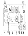
図7は第1の実施の形態における制御演算部8の構成を示す機能ブロック図である。図8は第1の実施の形態における制御演算部8の動作を示すフローチャートである。以下では、図7,8を用いて第1の実施の形態のモータ制御動作を説明する。なお、本説明の途中で図9及び図10も用いる。車両のイグニッションキースイッチ(不図示)がオンとなっている間、図8に示すモータ制御プログラムが繰り返し実行される。   FIG. 7 is a functional block diagram showing the configuration of the control calculation unit 8 in the first embodiment. FIG. 8 is a flowchart showing the operation of the control calculation unit 8 in the first embodiment. Hereinafter, the motor control operation of the first embodiment will be described with reference to FIGS. 9 and 10 are also used in the middle of this description. While the ignition key switch (not shown) of the vehicle is on, the motor control program shown in FIG. 8 is repeatedly executed.

図7に示すように、制御演算部8には、トルク要求演算部30、制動力要求演算部31、磁束演算部32、トルク推定演算部33、残留磁束密度演算部34、磁石温度演算部35、トルク制限演算部36、トルク目標演算部37、トルク指令演算部38、電流指令演算部39、PWM演算部40、制動力制限演算部41、制動力指令演算部42が設けられている。以下では、上述の各部が図8に示すモータ制御プログラム内でどのような動作をするか説明する。   As shown in FIG. 7, the control calculation unit 8 includes a torque request calculation unit 30, a braking force request calculation unit 31, a magnetic flux calculation unit 32, a torque estimation calculation unit 33, a residual magnetic flux density calculation unit 34, and a magnet temperature calculation unit 35. , A torque limit calculator 36, a torque target calculator 37, a torque command calculator 38, a current command calculator 39, a PWM calculator 40, a braking force limit calculator 41, and a braking force command calculator 42 are provided. Below, what operation | movement of the above-mentioned each part is demonstrated within the motor control program shown in FIG.

ステップS1では、車速センサ9が検出した車速信号と、アクセルセンサ10が検出したアクセル開度信号(アクセルペダルの踏み込み量に応じた信号)とに基づいて、トルク要求演算部30がモータ2のトルク要求値を計算する。具体的には、アクセルペダルのアクセル開度は車両としての出力要求値に比例するので、アクセル開度を出力要求値に換算する。そして、その出力要求値を車速で除算することで、車両の駆動力要求値、すなわちモータ2のトルク要求値を計算する。   In step S <b> 1, based on the vehicle speed signal detected by the vehicle speed sensor 9 and the accelerator opening signal detected by the accelerator sensor 10 (a signal corresponding to the amount of depression of the accelerator pedal), the torque request calculating unit 30 performs the torque of the motor 2. Calculate the required value. Specifically, since the accelerator opening of the accelerator pedal is proportional to the required output value as the vehicle, the accelerator opening is converted into the required output value. Then, the required driving force value of the vehicle, that is, the required torque value of the motor 2 is calculated by dividing the output required value by the vehicle speed.

ステップS2では、ブレーキセンサ11が検出したブレーキ信号(ブレーキペダルの踏み込み量に応じた信号)に基づいて、制動力要求演算部31が制動装置7の制動力要求値を計算する。ブレーキ信号は車両としての制動力要求値に比例するので、ブレーキ信号を制動力要求値に換算する。なお、制動力要求値はモータトルク相当に換算されており、車両を減速させるように働くので負値となる。   In step S <b> 2, the braking force request calculation unit 31 calculates the braking force request value of the braking device 7 based on the brake signal detected by the brake sensor 11 (a signal corresponding to the depression amount of the brake pedal). Since the brake signal is proportional to the required braking force value of the vehicle, the brake signal is converted into the required braking force value. Note that the required braking force value is converted to a motor torque equivalent and works negatively because the vehicle is decelerated.

ステップS3では、回転角センサ13が検出したロータ20の回転角信号と、ひずみセンサ15が検出したティース26のひずみ信号とに基づいて、磁束演算部32がティース26内の磁束推定値を計算する。なお、図6の説明箇所で述べたとおり、ロータ20の回転角信号が、ティース26内の磁束波形の正負いずれかを選択する役割を担っている。   In step S <b> 3, based on the rotation angle signal of the rotor 20 detected by the rotation angle sensor 13 and the strain signal of the tooth 26 detected by the strain sensor 15, the magnetic flux calculation unit 32 calculates an estimated magnetic flux value in the tooth 26. . As described in the explanation of FIG. 6, the rotation angle signal of the rotor 20 plays a role of selecting either positive or negative of the magnetic flux waveform in the tooth 26.

ステップS4では、電流センサ12が検出したコイル24の電流信号と、磁束演算部32が計算するティース26内の磁束推定値とに基づいて、トルク推定演算部33がモータ2のトルク推定値を計算する。なお、モータ2のトルクは、コイル24内の交流電流の振幅と、ティース26内の磁束の振幅と、交流電流と磁束の位相差によって決まる。すなわち、モータ2のトルクは、コイル24の交流電流とティース26内の磁束を最大振幅と位相差による極形式で表記した場合の外積となる。   In step S <b> 4, the torque estimation calculation unit 33 calculates the estimated torque value of the motor 2 based on the current signal of the coil 24 detected by the current sensor 12 and the estimated magnetic flux value in the tooth 26 calculated by the magnetic flux calculation unit 32. To do. The torque of the motor 2 is determined by the amplitude of the alternating current in the coil 24, the amplitude of the magnetic flux in the teeth 26, and the phase difference between the alternating current and the magnetic flux. That is, the torque of the motor 2 is an outer product in the case where the alternating current of the coil 24 and the magnetic flux in the tooth 26 are expressed in a polar format based on the maximum amplitude and phase difference.

ステップS5では、電流センサ12が検出したコイル24の電流信号と、磁束演算部32が計算するティース26内の磁束推定値とに基づいて、残留磁束密度演算部34が磁石21の残留磁束密度推定値を計算する。   In step S <b> 5, the residual magnetic flux density calculation unit 34 estimates the residual magnetic flux density of the magnet 21 based on the current signal of the coil 24 detected by the current sensor 12 and the estimated magnetic flux value in the tooth 26 calculated by the magnetic flux calculation unit 32. Calculate the value.

ここで、残留磁束密度演算部34と具体的な計算手順の詳細について、図9と図10を用いて説明する。図9は残留磁束密度演算部34の構成の詳細を示すブロック図である。図10は残留磁束密度演算部34の動作、すなわち、図8のステップS5の詳細を示すフローチャートである。残留磁束密度演算部34は、磁束振幅算出部50、電流振幅算出部51、位相差算出部52、および残留磁束密度算出部53を有する。図10のフローチャートを説明しながら上述の各部の動作を説明する。   Here, details of the residual magnetic flux density calculation unit 34 and a specific calculation procedure will be described with reference to FIGS. 9 and 10. FIG. 9 is a block diagram showing details of the configuration of the residual magnetic flux density calculator 34. FIG. 10 is a flowchart showing the operation of the residual magnetic flux density calculator 34, that is, the details of step S5 in FIG. The residual magnetic flux density calculator 34 includes a magnetic flux amplitude calculator 50, a current amplitude calculator 51, a phase difference calculator 52, and a residual magnetic flux density calculator 53. The operation of each unit described above will be described with reference to the flowchart of FIG.

ステップS51では、磁束演算部32で計算されたティース26内の磁束推定値に基づいて、磁束振幅算出部50が磁束の最大振幅を算出する。ステップS52では、電流センサ12が検出したコイル24の電流信号に基づいて、電流振幅算出部51が交流電流の最大振幅を算出する。ステップS53では、電流センサ12が検出したコイル24の電流信号と、磁束演算部32が計算するティース26内の磁束推定値とに基づいて、位相差算出部52がティース26内の磁束とコイル24の交流電流との間の位相差を算出する。   In step S51, the magnetic flux amplitude calculation unit 50 calculates the maximum magnetic flux amplitude based on the magnetic flux estimation value in the tooth 26 calculated by the magnetic flux calculation unit 32. In step S52, the current amplitude calculation unit 51 calculates the maximum amplitude of the alternating current based on the current signal of the coil 24 detected by the current sensor 12. In step S53, based on the current signal of the coil 24 detected by the current sensor 12 and the estimated magnetic flux value in the tooth 26 calculated by the magnetic flux calculation unit 32, the phase difference calculation unit 52 uses the magnetic flux in the tooth 26 and the coil 24. The phase difference between the current and the alternating current is calculated.

ステップS54では、磁束振幅算出部50が算出するティース26内の磁束推定値の最大振幅と、電流振幅算出部51が算出するコイル24の交流電流の最大振幅と、位相差算出部52が算出するティース26内の磁束推定値とコイル24の交流電流との間の位相差とに基づいて、残留磁束密度算出部53が磁石21の残留磁束密度推定値を算出する。ティース26内の磁束の最大振幅と、コイル24の交流電流の最大振幅と、ティース26内の磁束とコイル24の交流電流との間の位相差を入力パラメータとし、磁石21の残留磁束密度を出力パラメータとしたときの対応関係は、制御演算部8が備えるメモリ内に数値マップとして格納されている。ステップS54ではこの数値マップに基づいて、磁石21の残留磁束密度推定値を計算する。ステップS5内の最終ステップであるステップS54が終了すると、図8のステップS6に進む。   In step S54, the maximum amplitude of the magnetic flux estimation value in the tooth 26 calculated by the magnetic flux amplitude calculation unit 50, the maximum amplitude of the alternating current of the coil 24 calculated by the current amplitude calculation unit 51, and the phase difference calculation unit 52 calculate. Based on the phase difference between the magnetic flux estimation value in the tooth 26 and the alternating current of the coil 24, the residual magnetic flux density calculation unit 53 calculates the residual magnetic flux density estimation value of the magnet 21. Using the maximum amplitude of the magnetic flux in the tooth 26, the maximum amplitude of the alternating current in the coil 24, and the phase difference between the magnetic flux in the tooth 26 and the alternating current in the coil 24 as input parameters, the residual magnetic flux density of the magnet 21 is output. Correspondence when the parameters are used is stored as a numerical map in a memory included in the control calculation unit 8. In step S54, an estimated value of the residual magnetic flux density of the magnet 21 is calculated based on this numerical map. When step S54, which is the final step in step S5, ends, the process proceeds to step S6 in FIG.

図8に示すステップS6では、残留磁束密度演算部34が出力した磁石21の残留磁束密度推定値に基づいて、磁石温度演算部35が磁石21の温度推定値を計算する。磁石21の残留磁束密度を入力パラメータとし、温度を出力パラメータとしたときの対応関係は、制御演算部8が備えるメモリ内に数値マップとして格納されている。ステップS6ではこの数値マップに基づいて、磁石21の温度推定値を計算する。   In step S <b> 6 shown in FIG. 8, the magnet temperature calculator 35 calculates the estimated temperature of the magnet 21 based on the estimated residual flux density of the magnet 21 output from the residual flux density calculator 34. The correspondence when the residual magnetic flux density of the magnet 21 is an input parameter and the temperature is an output parameter is stored as a numerical map in a memory included in the control calculation unit 8. In step S6, an estimated temperature value of the magnet 21 is calculated based on this numerical map.

ステップS7では、回転角センサ13が検出したロータ20の回転角信号と、コイル温度センサ14が検出したコイル24の温度と、磁石温度演算部35が出力した磁石21の温度推定値とに基づいて、コイル24と磁石21を過度な温度上昇から保護するためのトルク制限処理をトルク制限演算部36が実行する。回転角センサ13が検出したロータ20の回転角信号からモータ2の回転数推定値が算出される。コイル24の温度と磁石21の温度とモータ2の回転数を入力パラメータとし、トルク制限値を出力パラメータとしたときの対応関係は、制御演算部8が備えるメモリ内に数値マップとして格納されている。ステップS7ではトルク制限演算部36が、この数値マップに基づいてトルク制限値を計算する。   In step S7, based on the rotation angle signal of the rotor 20 detected by the rotation angle sensor 13, the temperature of the coil 24 detected by the coil temperature sensor 14, and the estimated temperature value of the magnet 21 output by the magnet temperature calculation unit 35. The torque limit calculation unit 36 executes a torque limit process for protecting the coil 24 and the magnet 21 from excessive temperature rise. From the rotation angle signal of the rotor 20 detected by the rotation angle sensor 13, an estimated value of the number of rotations of the motor 2 is calculated. The correspondence relationship when the temperature of the coil 24, the temperature of the magnet 21 and the rotation speed of the motor 2 are input parameters and the torque limit value is an output parameter is stored as a numerical map in the memory provided in the control calculation unit 8. . In step S7, the torque limit calculation unit 36 calculates a torque limit value based on this numerical map.

ステップS8では、トルク要求演算部30が出力したモータ2のトルク要求値と、トルク制限演算部36が出力したモータ2のトルク制限値とに基づいて、トルク目標演算部37がトルク目標値を計算する。トルク制限として、力行側と回生側にそれぞれ、力行側トルク制限値と回生側トルク制限値が設けられている。力行側トルク制限値と回生側トルク制限値に挟まれたトルク範囲(トルク制限範囲)にトルク要求値が位置する場合は、トルク要求値がトルク目標値となる。力行側で、かつ、トルク制限範囲の外にトルク要求値が位置する場合は、力行側トルク制限値がトルク目標値となる。回生側で、かつ、トルク制限範囲の外にトルク要求値が位置する場合は、回生側トルク制限値がトルク目標値となる。   In step S8, the torque target calculation unit 37 calculates the torque target value based on the torque request value of the motor 2 output from the torque request calculation unit 30 and the torque limit value of the motor 2 output from the torque limit calculation unit 36. To do. As the torque limit, a power running side torque limit value and a regeneration side torque limit value are provided on the power running side and the regeneration side, respectively. When the torque request value is located in the torque range (torque limit range) sandwiched between the power running side torque limit value and the regeneration side torque limit value, the torque request value becomes the torque target value. When the required torque value is located outside the torque limit range on the power running side, the power running side torque limit value becomes the torque target value. When the required torque value is located outside the torque limit range on the regeneration side, the regeneration side torque limit value becomes the torque target value.

ステップS9では、トルク目標演算部37が出力したモータ2のトルク目標値と、トルク推定演算部33が出力したモータ2のトルク推定値とに基づいて、トルク指令演算部38がモータ2のトルク指令値を算出する。具体的には、トルク推定値とトルク目標値が等しい場合には、現行のトルク指令値を維持する。トルク推定値がトルク目標値よりも大きい場合には、トルク推定値をトルク目標値に近づけるためにトルク指令値を現行のトルク指令値よりも低くする。トルク推定値がトルク目標値よりも小さい場合には、トルク推定値をトルク目標値に近づけるためにトルク指令値を現行のトルク指令値よりも高くする。このように、トルク推定値がトルク目標値と一致するようにトルク指令演算部38がトルク指令値を算出する。   In step S <b> 9, based on the torque target value of the motor 2 output from the torque target calculation unit 37 and the estimated torque value of the motor 2 output from the torque estimation calculation unit 33, the torque command calculation unit 38 performs the torque command of the motor 2. Calculate the value. Specifically, when the estimated torque value is equal to the target torque value, the current torque command value is maintained. When the estimated torque value is larger than the target torque value, the torque command value is set lower than the current torque command value in order to bring the estimated torque value closer to the target torque value. When the estimated torque value is smaller than the target torque value, the torque command value is set higher than the current torque command value in order to bring the estimated torque value closer to the target torque value. In this manner, the torque command calculation unit 38 calculates the torque command value so that the estimated torque value matches the torque target value.

ステップS10では、トルク指令演算部38が出力したモータ2のトルク指令値と、残留磁束密度演算部34が出力した磁石21の残留磁束密度推定値と、回転角センサ13が検出したロータ20の回転角信号とに基づいて、電流指令演算部39がコイル24の電流指令値を計算する。回転角センサ13が検出したロータ20の回転角信号からモータ2の回転数推定値が算出される。モータ2の回転数とトルクおよび磁石21の残留磁束密度を入力パラメータとし、コイル24の電流を出力パラメータとしたときの対応関係は、制御演算部8が備えるメモリ内に数値マップとして格納されている。電流指令演算部39は、この数値マップに基づいて、コイル24の電流指令値を計算する。   In step S 10, the torque command value of the motor 2 output from the torque command calculation unit 38, the estimated residual magnetic flux density value of the magnet 21 output from the residual magnetic flux density calculation unit 34, and the rotation of the rotor 20 detected by the rotation angle sensor 13. Based on the angle signal, the current command calculation unit 39 calculates the current command value of the coil 24. From the rotation angle signal of the rotor 20 detected by the rotation angle sensor 13, an estimated value of the number of rotations of the motor 2 is calculated. The correspondence relationship when the rotational speed and torque of the motor 2 and the residual magnetic flux density of the magnet 21 are input parameters and the current of the coil 24 is an output parameter is stored as a numerical map in the memory included in the control calculation unit 8. . The current command calculation unit 39 calculates the current command value of the coil 24 based on this numerical map.

ステップS11では、電流指令演算部39が出力した電流指令値と、電流センサ12で検出されるコイル24の電流信号と、回転角センサ13で検出されたロータ20の回転角信号とに基づいて、PWM演算部40は、パルス幅変調(PWM)方式によりインバータ電源3のスイッチ素子のオンオフPWMパルスを生成して出力する。   In step S11, based on the current command value output from the current command calculation unit 39, the current signal of the coil 24 detected by the current sensor 12, and the rotation angle signal of the rotor 20 detected by the rotation angle sensor 13, The PWM calculation unit 40 generates and outputs an on / off PWM pulse of the switch element of the inverter power supply 3 by a pulse width modulation (PWM) method.

ステップS12では、車速センサ9で検出された車速信号と、磁石温度演算部35が出力した磁石21の温度推定値と、トルク推定演算部33が出力したモータ2のトルク推定値とに基づいて、磁石21を過度な温度上昇から保護するための制動装置7の制動力制限値を制動力制限演算部41が計算する。磁石21の温度が所定温度以上であり、かつモータ2のトルクがゼロであるにも関わらず車速が上昇する場合には、車速が車速制限値以下となる指令値を制動力制限値とする。上記以外の場合には、制動力要求値をゼロとする。磁石21の推定温度とトルク推定値と車速信号とを入力パラメータとし、車速制限値を出力パラメータとしたときの対応関係は、制御演算部8が備えるメモリ内に数値マップとして格納されている。制動力制限演算部41がこの数値マップに基づいて、車速制限値を計算する。これにより、モータ回転数を低下させ、磁石21の過度な温度上昇を避けることができる。   In step S12, based on the vehicle speed signal detected by the vehicle speed sensor 9, the estimated temperature value of the magnet 21 output from the magnet temperature calculation unit 35, and the estimated torque value of the motor 2 output from the torque estimation calculation unit 33, The braking force limit calculation unit 41 calculates a braking force limit value of the braking device 7 for protecting the magnet 21 from excessive temperature rise. When the temperature of the magnet 21 is equal to or higher than a predetermined temperature and the vehicle speed increases despite the torque of the motor 2 being zero, the command value at which the vehicle speed is equal to or lower than the vehicle speed limit value is set as the braking force limit value. In cases other than the above, the required braking force value is set to zero. The correspondence when the estimated temperature of the magnet 21, the estimated torque value, and the vehicle speed signal are input parameters and the vehicle speed limit value is an output parameter is stored as a numerical map in the memory provided in the control calculation unit 8. The braking force limit calculation unit 41 calculates a vehicle speed limit value based on this numerical map. Thereby, motor rotation speed can be reduced and the excessive temperature rise of the magnet 21 can be avoided.

ステップS13では、制動力要求演算部31が出力した制動力装置7の制動力要求値と、制動力制限演算部41が出力した制動装置7の制動力制限値とに基づいて、制動力指令演算部42が制動装置7へ送信する制動力指令値を計算する。   In step S13, a braking force command calculation is performed based on the braking force request value of the braking force device 7 output from the braking force request calculation unit 31 and the braking force limit value of the braking device 7 output from the braking force limit calculation unit 41. The braking force command value transmitted from the unit 42 to the braking device 7 is calculated.

以上説明した制御演算部8の各部をまとめると以下のとおりである。
(1)トルク要求演算部30は、アクセル開度と車速からトルク要求値を演算する。
(2)磁束演算部32は、ティースひずみおよび回転角を用いてティース内磁束を演算する。
(3)トルク推定値演算部33は、ティース内磁束とコイル電流からトルク推定値を演算してトルク目標演算部37に出力する。
(4)残留磁束密度演算部34は、ティース内磁束、および、コイル電流と前記演算されたティース内の磁束の位相差から残留磁束密度推定値を演算する。
(5)磁石温度演算35は、残留磁束密度推定値から磁石温度推定値を演算する。
(6)トルク制限演算部36は、コイル温度、回転角信号、磁石温度推定値の3つの信号からトルク制限値を演算する。
(7)トルク目標演算部37は、トルク要求値がトルク制限値を超えないようにトルク目標を演算する。
(8)トルク指令演算部38は、トルク推定値がトルク目標値に一致するようにトルク指令を演算する。
(9)電流指令演算部39は、トルク指令値と、回転角と、磁石温度推定値の3つの信号を使用して電流指令を演算する。
(10)PWM演算部40は、電流指令と、コイル電流と、回転角の3つの信号を使用してPWMパルスであるスイッチング動作指令を演算する。
(11)制動力演算部31は、ブレーキ開度信号から制動力要求を演算する。
(12)制動力制限演算部41は、車速信号と、磁石温度推定値と、トルク推定値の3つの信号を使用して制動力制限値を演算する。
(13)制動力指令演算部42は、制動力要求と制動力制限値から制動力指令を演算する。
The parts of the control arithmetic unit 8 described above are summarized as follows.
(1) The torque request calculation unit 30 calculates a torque request value from the accelerator opening and the vehicle speed.
(2) The magnetic flux calculation unit 32 calculates the magnetic flux in the teeth using the tooth strain and the rotation angle.
(3) The estimated torque value calculator 33 calculates the estimated torque value from the magnetic flux in the teeth and the coil current, and outputs it to the torque target calculator 37.
(4) The residual magnetic flux density calculation unit 34 calculates the residual magnetic flux density estimated value from the magnetic flux in the tooth and the phase difference between the coil current and the calculated magnetic flux in the tooth.
(5) The magnet temperature calculation 35 calculates the magnet temperature estimated value from the residual magnetic flux density estimated value.
(6) The torque limit calculation unit 36 calculates a torque limit value from three signals of the coil temperature, the rotation angle signal, and the magnet temperature estimated value.
(7) The torque target calculation unit 37 calculates the torque target so that the torque request value does not exceed the torque limit value.
(8) The torque command calculation unit 38 calculates the torque command so that the estimated torque value matches the torque target value.
(9) The current command calculation unit 39 calculates a current command using three signals: a torque command value, a rotation angle, and a magnet temperature estimated value.
(10) The PWM calculation unit 40 calculates a switching operation command that is a PWM pulse by using three signals of a current command, a coil current, and a rotation angle.
(11) The braking force calculation unit 31 calculates a braking force request from the brake opening signal.
(12) The braking force limit calculation unit 41 calculates the braking force limit value using the three signals of the vehicle speed signal, the magnet temperature estimated value, and the torque estimated value.
(13) The braking force command calculation unit 42 calculates a braking force command from the braking force request and the braking force limit value.

以上で説明した第1の実施の形態におけるモータ2またはモータ駆動装置100は、以下のような作用効果を奏する。
(1)モータ2のティース26にひずみセンサ15が設けられていることにより、ティース26の磁気吸引力によるひずみが検出できる。さらに、ティース26のひずみと、ロータ20の回転角とからティース26内の磁束推定値が求められる。さらに、ティース26内の磁束とコイル24の電流から、磁石21の残留磁束密度推定値が求められる。
The motor 2 or the motor drive device 100 according to the first embodiment described above has the following operational effects.
(1) Since the strain sensor 15 is provided in the tooth 26 of the motor 2, the strain due to the magnetic attraction force of the tooth 26 can be detected. Further, an estimated magnetic flux value in the tooth 26 is obtained from the distortion of the tooth 26 and the rotation angle of the rotor 20. Further, an estimated value of the residual magnetic flux density of the magnet 21 is obtained from the magnetic flux in the tooth 26 and the current in the coil 24.

(2)ティース26のひずみセンサ15がティース26の径方向のひずみを検出するようにしたことにより、コイル24の占積率やひずみセンサ15の取り付け位置によって変化しない径方向のひずみを高精度に検出することができ、磁気吸引力によるひずみが精度よく検出できる。 (2) Since the strain sensor 15 of the tooth 26 detects the strain in the radial direction of the tooth 26, the strain in the radial direction that does not vary depending on the space factor of the coil 24 and the mounting position of the strain sensor 15 can be obtained with high accuracy. It is possible to detect and distortion due to magnetic attractive force can be detected with high accuracy.

(3)ティース26のひずみセンサ15がティース26の周方向中央に設けられるようにしたことにより、周方向の曲げ応力による径方向成分が少なくなり、磁気吸引力によるひずみが精度よく検出できる。
(4)ティース26のひずみセンサ15がティース26の先端側に設けられたことにより、曲げ応力が小さくなり、磁気吸引力によるひずみが精度よく検出できる。
(3) Since the strain sensor 15 of the tooth 26 is provided at the center in the circumferential direction of the tooth 26, the radial component due to the bending stress in the circumferential direction is reduced, and the strain due to the magnetic attractive force can be accurately detected.
(4) Since the strain sensor 15 of the tooth 26 is provided on the distal end side of the tooth 26, the bending stress is reduced, and the strain due to the magnetic attractive force can be detected with high accuracy.

(5)回転電機駆動装置100は、回転電機2と、直流電流を交流電力に変換して回転電機に供給するインバータ電源3と、インバータ電源3のスイッチング動作指令信号を演算する制御演算部8とを備え、制御演算部8は、ひずみ検出センサ15の検出値に基づいて磁石21の残留磁束密度推定値を算出する残留磁束密度推定値演算部34を有する。制御演算部8は、残留磁束密度推定値演算部34で演算された残留磁束密度推定値に基づいてスイッチング動作指令信号を演算してインバータ電源3に出力する。すなわち、モータ2のティース26に設けたひずみセンサ15の検出値に基づいて磁石21の残留磁束密度推定値が残留磁束密度推定値演算部34により求められる。モータ駆動制御装置100は、磁石21の残留磁束密度推定値に基づいてスイッチング動作指令信号を演算してモータ2を駆動制御する。これにより。トルク精度を向上させることができる。 (5) The rotating electrical machine driving apparatus 100 includes the rotating electrical machine 2, an inverter power supply 3 that converts a direct current into AC power and supplies the rotating electrical machine, and a control calculation unit 8 that calculates a switching operation command signal of the inverter power supply 3. The control calculation unit 8 includes a residual magnetic flux density estimated value calculation unit 34 that calculates a residual magnetic flux density estimated value of the magnet 21 based on the detection value of the strain detection sensor 15. The control calculation unit 8 calculates a switching operation command signal based on the residual magnetic flux density estimated value calculated by the residual magnetic flux density estimated value calculation unit 34 and outputs it to the inverter power supply 3. That is, the residual magnetic flux density estimated value of the magnet 21 is obtained by the residual magnetic flux density estimated value calculation unit 34 based on the detection value of the strain sensor 15 provided on the tooth 26 of the motor 2. The motor drive control device 100 controls the drive of the motor 2 by calculating a switching operation command signal based on the estimated residual magnetic flux density of the magnet 21. By this. Torque accuracy can be improved.

(6)制御演算部8は、残留磁束密度推定値とコイル電流とに基づいて回転電機2のトルク推定値を演算するトルク推定演算部33と、トルク要求値に基づいたトルク目標値を演算するトルク目標演算部37と、トルク推定値がトルク目標値に一致するようにトルク指令を演算するトルク指令演算部38とを備える。モータ駆動装置100が磁石21の残留磁束密度推定値とコイル24の電流に基づいて算出されたトルク推定値とトルク目標値が一致するようにモータ2を駆動制御するようにしたことにより、トルク精度を向上させることができる。 (6) The control calculation unit 8 calculates a torque estimation calculation unit 33 that calculates a torque estimation value of the rotating electrical machine 2 based on the residual magnetic flux density estimation value and the coil current, and calculates a torque target value based on the torque request value. A torque target calculation unit 37 and a torque command calculation unit 38 that calculates a torque command so that the estimated torque value matches the torque target value are provided. The motor drive device 100 controls the motor 2 so that the estimated torque value calculated based on the residual magnetic flux density value of the magnet 21 and the current of the coil 24 and the torque target value coincide with each other. Can be improved.

−第1の実施の形態の変形例−
第1の実施の形態を以下のように変形して実施形してもよい。
モータ駆動装置100の制御演算部8は、磁石温度演算部35で算出した磁石21の温度推定値を基準温度より高い所定温度と比較し、その比較結果によりモータ2を駆動制御するようにしてもよい。
-Modification of the first embodiment-
The first embodiment may be modified and implemented as follows.
The control calculation unit 8 of the motor drive device 100 compares the estimated temperature value of the magnet 21 calculated by the magnet temperature calculation unit 35 with a predetermined temperature higher than the reference temperature, and controls the motor 2 based on the comparison result. Good.

たとえば、上述の磁石21の温度推定値が所定値以上になると、モータ駆動装置100がモータ2のトルクまたは回転数を低下させるようにモータ2を駆動制御するようにしてもよい。   For example, when the estimated temperature value of the magnet 21 is equal to or higher than a predetermined value, the motor drive device 100 may drive and control the motor 2 so as to reduce the torque or the rotational speed of the motor 2.

あるいはまた、上述の磁石21の残留磁束密度推定値が所定値以下になると、モータ駆動装置100がモータ2のトルクまたは回転数を低下させるようにモータ2を駆動制御するようにしてもよい。
変形例の回転電機駆動装置において、制御演算部8は、残留磁束密度推定値に基づいて磁石21の温度推定値を算出する磁石温度演算部35を有し、温度推定値を基準温度より高い所定温度と比較した結果によりスイッチング動作指令信号を演算して出力するようにした。たとえば、制御演算部8は、温度推定値が所定温度以上になると、回転電機2のトルクまたは回転数を低下させるようにスイッチング動作指令信号を演算して出力する。以上の変形例によれば、磁石21やコイル24の過度な温度上昇を抑制することができる。
Alternatively, when the estimated value of the residual magnetic flux density of the magnet 21 becomes a predetermined value or less, the motor drive device 100 may drive and control the motor 2 so as to reduce the torque or the rotation speed of the motor 2.
In the rotating electrical machine drive device according to the modification, the control calculation unit 8 includes a magnet temperature calculation unit 35 that calculates the temperature estimation value of the magnet 21 based on the residual magnetic flux density estimation value, and the temperature estimation value is a predetermined value higher than the reference temperature. The switching operation command signal is calculated and output based on the result of comparison with the temperature. For example, when the estimated temperature value exceeds a predetermined temperature, the control calculation unit 8 calculates and outputs a switching operation command signal so as to reduce the torque or the rotation speed of the rotating electrical machine 2. According to the above modification, an excessive temperature rise of the magnet 21 and the coil 24 can be suppressed.

−第2の実施の形態−
図11は、本発明の第2の実施の形態におけるモータ駆動装置100を搭載した電気自動車200の概略構成を示す図である。図12は第2の実施の形態における制御演算部8の構成を示すブロック図である。第2の実施の形態は、上述した第1の実施の形態の制御演算部8の構成を変更したものである。図1、図7に示す要素と同様の要素に対しては同一の符号を付し、以下では相違点を中心に説明する。
-Second Embodiment-
FIG. 11 is a diagram showing a schematic configuration of an electric vehicle 200 on which the motor drive device 100 according to the second embodiment of the present invention is mounted. FIG. 12 is a block diagram showing a configuration of the control calculation unit 8 in the second embodiment. In the second embodiment, the configuration of the control calculation unit 8 of the first embodiment described above is changed. Elements similar to those shown in FIGS. 1 and 7 are given the same reference numerals, and the differences will be mainly described below.

第2の実施の形態における制御演算部8は、モータ2に印加する電流の大きさや交流電流の周波数を演算する第1の制御演算部61と、モータ2のトルク要求値を演算する第2の制御演算部62から構成される。第1の制御演算部61と第2の制御演算部62は、それぞれ別のCPUやメモリで構成されている。   The control calculation unit 8 in the second embodiment includes a first control calculation unit 61 that calculates the magnitude of the current applied to the motor 2 and the frequency of the alternating current, and a second calculation unit that calculates a torque request value of the motor 2. The control calculation unit 62 is configured. The first control calculation unit 61 and the second control calculation unit 62 are configured by different CPUs and memories, respectively.

第2の制御演算部62は主に、モータ2によらない演算を実行する。第2の制御演算部62には、車速センサ9、アクセルセンサ10、ブレーキセンサ11、などが接続されている。第2の制御演算部62はモータ2のトルク要求値を演算し、第1の制御演算部61に送信する。   The second control calculation unit 62 mainly performs calculations that do not depend on the motor 2. A vehicle speed sensor 9, an accelerator sensor 10, a brake sensor 11, and the like are connected to the second control calculation unit 62. The second control calculation unit 62 calculates a torque request value of the motor 2 and transmits it to the first control calculation unit 61.

第1の制御演算部61は主に、モータ2に固有の演算を実行する。第1の制御演算部61には、電流センサ12、回転角センサ13、コイル温度センサ14、ひずみセンサ15、などが接続されている。第1の制御演算部61は、第2の制御演算62が送信したトルク要求値から、モータ2に印加する電流の大きさや交流電流の周波数を演算し、インバータ電源3へ指令するとともに、モータ2のトルクや、磁石21の温度を演算し、第2の制御演算部62へ送信する。   The first control calculation unit 61 mainly executes a calculation specific to the motor 2. A current sensor 12, a rotation angle sensor 13, a coil temperature sensor 14, a strain sensor 15, and the like are connected to the first control calculation unit 61. The first control calculation unit 61 calculates the magnitude of the current applied to the motor 2 and the frequency of the alternating current from the torque request value transmitted by the second control calculation 62, instructs the inverter power supply 3, and outputs the motor 2 And the temperature of the magnet 21 are calculated and transmitted to the second control calculation unit 62.

このように、モータ2に固有の演算を行う第1の制御演算部61と、モータ2によらない演算を行う第2の制御演算部62を別に構成することで、プログラムのメンテナンス性を向上させることができる。例えば車両のスペックが変更になり、モータ2の特性が変わった場合には、第1の制御演算部61のみを修正すればよい。   As described above, by separately configuring the first control calculation unit 61 that performs calculations specific to the motor 2 and the second control calculation unit 62 that performs calculations that do not depend on the motor 2, the maintainability of the program is improved. be able to. For example, when the vehicle specifications change and the characteristics of the motor 2 change, only the first control calculation unit 61 needs to be corrected.

第2の実施の形態における制御演算部8は、第1の制御演算部61を、第2の制御演算部62に比べてモータ2の近傍に設け、電流センサ12、回転角センサ13、コイル温度センサ14、ひずみセンサ15の検出値に基づいて、モータ2のトルクや、磁石21の温度を演算し、第2の制御演算部62へ送信する。これにより、ひずみセンサ15や電流センサ12の検出値が、通信遅れや通信ノイズの影響を受けることなく、モータ2のトルクや、磁石21の温度を演算することができる。   In the control calculation unit 8 in the second embodiment, the first control calculation unit 61 is provided closer to the motor 2 than the second control calculation unit 62, and the current sensor 12, the rotation angle sensor 13, the coil temperature is provided. Based on the detection values of the sensor 14 and the strain sensor 15, the torque of the motor 2 and the temperature of the magnet 21 are calculated and transmitted to the second control calculation unit 62. As a result, the detected values of the strain sensor 15 and the current sensor 12 can calculate the torque of the motor 2 and the temperature of the magnet 21 without being affected by communication delay or communication noise.

−第3の実施の形態−
図13は、本発明の第3の実施の形態におけるモータ駆動装置100を搭載した電気自動車200の概略構成を示す図である。図14は第3の実施の形態におけるモータ2の構成を示す図である。図15は第3の実施の形態における制御演算部8の構成を示すブロック図である。第3の実施の形態では、上述した第1の実施の形態の一部の構成を変更したものである。図1、図2、図7に示す要素と同様の要素に対しては同一の符号を付し、以下では相違点を中心に説明する。
-Third embodiment-
FIG. 13 is a diagram showing a schematic configuration of an electric vehicle 200 on which the motor drive device 100 according to the third embodiment of the present invention is mounted. FIG. 14 is a diagram illustrating a configuration of the motor 2 according to the third embodiment. FIG. 15 is a block diagram showing a configuration of the control calculation unit 8 in the third embodiment. In the third embodiment, a part of the configuration of the first embodiment described above is changed. Elements similar to those shown in FIGS. 1, 2, and 7 are denoted by the same reference numerals, and different points will be mainly described below.

第3の実施の形態におけるモータ2は、ティース26の温度を検出するティース温度センサ71を備えている。第3の実施の形態における磁束演算部32は、回転角センサ13が検出したロータ20の回転角信号と、ひずみセンサ15が検出したティース26のひずみ信号と、ティース温度センサ71が検出したティース26の温度に基づいて、ティース26内の磁束推定値を計算する。ティース26の応力とひずみの関係はティース26のヤング率に依存する。またティース26のヤング率は、ティース26の温度に依存し、温度が高くなるとヤング率は低下する。第3の実施の形態における磁束演算部32は、ティース温度センサ71が検出したティース26の温度を用いて、ひずみセンサ15で検出したひずみのうち、温度によるひずみ成分を除外するようにティース26内の磁束推定値を補正することにより、ティース26の温度の影響を受けることなく、ティース26内の磁束推定値を高精度に算出できる。   The motor 2 in the third embodiment includes a tooth temperature sensor 71 that detects the temperature of the tooth 26. The magnetic flux calculation unit 32 in the third embodiment includes the rotation angle signal of the rotor 20 detected by the rotation angle sensor 13, the strain signal of the tooth 26 detected by the strain sensor 15, and the tooth 26 detected by the tooth temperature sensor 71. Based on the temperature, the estimated magnetic flux value in the tooth 26 is calculated. The relationship between the stress and strain of the tooth 26 depends on the Young's modulus of the tooth 26. The Young's modulus of the teeth 26 depends on the temperature of the teeth 26, and the Young's modulus decreases as the temperature increases. The magnetic flux calculation unit 32 in the third embodiment uses the temperature of the tooth 26 detected by the tooth temperature sensor 71 to exclude the strain component due to the temperature from the strain detected by the strain sensor 15. By correcting the estimated magnetic flux value, the estimated magnetic flux value in the tooth 26 can be calculated with high accuracy without being affected by the temperature of the tooth 26.

以上、本発明をインナーロータモータに適用した例で説明してきたが、本発明は、アウターロータモータにおいても同様に適用できる。アウターロータモータにおいても、ひずみセンサ15は、ティースの先端側に取り付けられるのが望ましい。ただし、アウターロータモータでは、ロータがステータの外周側に配置されるので、ティースの先端側は径方向外側となる。ひずみセンサ15がティースの周方向の中央に取り付けられることは、アウターロータモータにおいてもインナーロータモータと同様である。   As described above, the present invention has been described with the example applied to the inner rotor motor, but the present invention can be similarly applied to the outer rotor motor. Also in the outer rotor motor, the strain sensor 15 is preferably attached to the tip side of the teeth. However, in the outer rotor motor, since the rotor is disposed on the outer peripheral side of the stator, the tip side of the teeth is radially outward. The fact that the strain sensor 15 is attached to the center in the circumferential direction of the teeth is the same as that of the inner rotor motor in the outer rotor motor.

以上で説明した実施形態では、本発明を車両の唯一の駆動源とする電気自動車の駆動システムに適用した場合を例に挙げている。しかし、本発明は、鉄道車両や建設車両などの電動車両、内燃機関であるエンジンと電動機とを車両の駆動源とする電動車両、例えばハイブリッド自動車(乗用車)、ハイブリッドトラックなどの貨物自動車、ハイブリッドバスなどの乗り合い自動車などの制御装置にも適用することができる。   In the embodiment described above, the case where the present invention is applied to a drive system of an electric vehicle using the sole drive source of the vehicle is taken as an example. However, the present invention relates to an electric vehicle such as a railway vehicle or a construction vehicle, an electric vehicle using an engine and an electric motor as an internal combustion engine as a driving source of the vehicle, for example, a hybrid vehicle (passenger car), a freight vehicle such as a hybrid truck, a hybrid bus The present invention can also be applied to a control device such as a shared car.

1:バッテリ 2:モータ
3:インバータ電源 4:減速機
5:差動機構 6:駆動輪
7:制動装置 8:制御演算部
9:車速センサ 10:アクセルセンサ
11:ブレーキセンサ 12:電流センサ
13:回転角センサ 14:コイル温度センサ
15:ひずみセンサ 20:ロータ
21:磁石 22:ケース
23:軸受 24:コイル
25:ステータ 26:ティース
30:トルク要求演算部 31:制動力要求演算部
32:磁束演算部 33:トルク推定演算部
34:残留磁束密度演算部 35:磁石温度演算部
36:トルク制限演算部 37:トルク目標演算部
38:トルク指令演算部 39:電流指令演算部
40:PWM演算部 41:制動力制限演算部
42:制動力指令演算部 50:磁束振幅算出部
51:電流振幅算出部 52:位相差算出部
53:残留磁束密度算出部 61:第1の制御演算部
62:第2の制御演算部 71:ティース温度センサ
100:モータ駆動装置 200:電気自動車
1: Battery 2: Motor 3: Inverter power supply 4: Reducer 5: Differential mechanism 6: Drive wheel 7: Braking device 8: Control operation unit 9: Vehicle speed sensor 10: Acceleration sensor 11: Brake sensor 12: Current sensor 13: Rotation angle sensor 14: Coil temperature sensor 15: Strain sensor 20: Rotor 21: Magnet 22: Case 23: Bearing 24: Coil 25: Stator 26: Teeth 30: Torque request calculation unit 31: Braking force request calculation unit 32: Magnetic flux calculation Unit 33: Torque estimation calculation unit 34: Residual magnetic flux density calculation unit 35: Magnet temperature calculation unit 36: Torque limit calculation unit 37: Torque target calculation unit 38: Torque command calculation unit 39: Current command calculation unit 40: PWM calculation unit 41 : Braking force limit calculation unit 42: Braking force command calculation unit 50: Magnetic flux amplitude calculation unit 51: Current amplitude calculation unit 52: Phase difference calculation unit 53: Residual magnetic flux density calculation unit 61: First control calculation unit 62: Second control calculation unit 71: Teeth temperature sensor 100: Motor drive device 200: Electric vehicle

Claims (15)

周方向に配置された複数のティースにコイルが巻回されてなる固定子と、周方向に配置された磁石を有し、前記固定子の径方向内側または外側に配設される回転子と前記複数のティースの少なくとも一つに設けられた前記ティースのひずみを検出するひずみ検出部とを備えた回転電機と、
前記ひずみ検出部の検出値から前記ティース内の磁束を演算し、前記演算された前記ティース内の磁束、および、前記コイルに流れるコイル電流と前記演算された前記ティース内の磁束との位相差に基づいて前記磁石の残留磁束密度推定値を演算する制御部と、
を有する回転電機制御装置。
A stator in which a coil is wound around a plurality of teeth disposed in the circumferential direction, a magnet disposed in the circumferential direction, and a rotor disposed on the radially inner side or the outer side of the stator ; A rotating electrical machine including a strain detection unit that detects strain of the teeth provided in at least one of the plurality of teeth ;
The magnetic flux in the teeth is calculated from the detection value of the strain detector, and the calculated magnetic flux in the teeth, and the phase difference between the coil current flowing in the coil and the calculated magnetic flux in the teeth. A control unit for calculating an estimated value of the residual magnetic flux density of the magnet,
A rotating electrical machine control device comprising:
請求項1に記載の回転電機制御装置において、
前記ひずみ検出部は、前記ティースの径方向に沿った向きのひずみを検出するように、前記ティースにおける回転軸方向端面のうちのいずれか一方に設けられている回転電機制御装置
In the rotating electrical machine control device according to claim 1,
The said distortion | strain detection part is a rotary electric machine control apparatus provided in any one of the rotating shaft direction end surfaces in the said teeth so that the distortion of the direction along the radial direction of the said teeth may be detected.
請求項2に記載の回転電機制御装置において、
前記ひずみ検出部は、前記ティースの周方向中央に設けられる回転電機制御装置
In the rotating electrical machine control device according to claim 2,
The said distortion | strain detection part is a rotary electric machine control apparatus provided in the circumferential direction center of the said teeth.
請求項2または3に記載の回転電機制御装置において、
前記ひずみ検出部は、前記ティースの先端側に設けられる回転電機制御装置
In the rotary electric machine control device according to claim 2 or 3,
The strain detector is a rotating electrical machine control device provided on a tip side of the teeth.
請求項1〜4のいずれか一項に記載の回転電機制御装置において
直流電流を交流電流に変換して前記回転電機に供給するインバータ電源備え、
前記制御部は、前記ひずみ検出部の検出値に基づいて前記磁石の残留磁束密度推定値を算出し、前記算出された前記残留磁束密度推定値に基づいて前記インバータ電源のスイッチング動作指令信号を演算して前記インバータ電源に出力する回転電機制御装置。
In the rotary electric machine control device according to any one of claims 1 to 4,
An inverter power supply that converts a direct current into an alternating current and supplies the rotating electrical machine;
The control unit calculates a residual magnetic flux density estimation value of the magnet based on the detection value of the strain detection unit, and calculates a switching operation command signal of the inverter power supply based on the calculated residual magnetic flux density estimation value The rotating electrical machine control device that outputs to the inverter power supply.
請求項5に記載の回転電機制御装置において、
前記制御部は、前記残留磁束密度推定値とコイル電流とに基づいて前記回転電機のトルク推定値を演算するトルク推定演算部と、トルク要求値に基づいたトルク目標値を演算するトルク目標演算部と、前記トルク推定値が前記トルク目標値に一致するようにトルク指令を演算するトルク指令演算部とを備える回転電機制御装置。
In the rotating electrical machine control device according to claim 5,
The control unit includes a torque estimation calculation unit that calculates a torque estimation value of the rotating electrical machine based on the residual magnetic flux density estimation value and a coil current, and a torque target calculation unit that calculates a torque target value based on a torque request value When the rotating electric machine control device and a torque command computation unit for the torque estimated value calculating a torque command to match the torque target value.
請求項に記載の回転電機制御装置において、
前記制御部は、前記トルク要求値を演算するトルク要求演算部を前記トルク推定演算部とは別に有し、
前記トルク推定演算部は、前記トルク要求演算部に比べて前記回転電機の近傍に設けられている回転電機制御装置。
In the rotating electrical machine control device according to claim 6 ,
The control unit has a torque request calculation unit that calculates the torque request value separately from the torque estimation calculation unit,
The said torque estimation calculating part is a rotary electric machine control apparatus provided in the vicinity of the said rotary electric machine compared with the said torque request | requirement calculating part.
請求項5に記載の回転電機制御装置において、
前記制御部は、前記残留磁束密度推定値に基づいて前記磁石の温度推定値を算出する磁石温度演算部を有し、前記磁石の温度推定値と基準温度より高い所定温度とを比較した結果により前記スイッチング動作指令信号を演算して出力する回転電機制御装置。
In the rotating electrical machine control device according to claim 5,
The control unit includes a magnet temperature calculation unit that calculates an estimated temperature value of the magnet based on the estimated value of the residual magnetic flux density, and a result of comparing the estimated temperature value of the magnet with a predetermined temperature higher than a reference temperature. A rotating electrical machine control device that calculates and outputs the switching operation command signal.
請求項に記載の回転電機制御装置において、
前記制御部は、トルク要求値を演算するトルク要求演算部を前記磁石温度演算部とは別に有し、
前記磁石温度演算部は、前記トルク要求演算部に比べて前記回転電機の近傍に設けられる回転電機制御装置。
In the rotating electrical machine control device according to claim 8 ,
The control unit has a torque request calculation unit that calculates a torque request value separately from the magnet temperature calculation unit,
The said magnet temperature calculating part is a rotary electric machine control apparatus provided in the vicinity of the said rotary electric machine compared with the said torque request | requirement calculating part.
請求項またはに記載の回転電機制御装置において、
前記制御部は、前記温度推定値が前記所定温度以上になると、前記回転電機のトルクまたは回転数を低下させる電流指令を演算して出力する回転電機制御装置。
In the rotary electric machine control device according to claim 8 or 9 ,
The said control part is a rotary electric machine control apparatus which calculates and outputs the electric current command which reduces the torque or the rotation speed of the said rotary electric machine, if the said temperature estimated value becomes more than the said predetermined temperature.
請求項10に記載の回転電機制御装置において、
前記制御部は、前記磁石温度演算部で演算した前記温度推定値が前記所定温度以上になると前記回転電機のトルクまたは回転数を低下させる電流指令を演算する電流指令演算部と、前記電流指令に基づいて前記スイッチング動作指令信号をPWMパルスとして演算するPWM演算部とを有する回転電機制御装置。
In the rotating electrical machine control device according to claim 10 ,
The control unit includes a current command calculation unit that calculates a current command for reducing torque or rotation speed of the rotating electrical machine when the estimated temperature value calculated by the magnet temperature calculation unit is equal to or higher than the predetermined temperature; A rotating electrical machine control device comprising: a PWM calculation unit that calculates the switching operation command signal as a PWM pulse based on the PWM operation command signal.
請求項5〜10のいずれか一項に記載の回転電機制御装置において、
前記制御部は、前記残留磁束密度推定値が所定値以下になると、前記回転電機のトルクまたは回転数を低下させるように前記スイッチング動作指令信号を演算して出力する回転電機制御装置。
In the rotary electric machine control device according to any one of claims 5 to 10 ,
The control unit is a rotating electrical machine control device that calculates and outputs the switching operation command signal so as to reduce the torque or the rotational speed of the rotating electrical machine when the estimated value of the residual magnetic flux density becomes a predetermined value or less.
請求項12に記載の回転電機制御装置において、
前記制御部は、前記残留磁束密度推定値が所定値以下になると前記回転電機のトルクまたは回転数を低下させるように前記回転電機のトルクまたは回転数を低下させる電流指令を演算する電流指令演算部と、前記電流指令に基づいて前記スイッチング動作指令信号をPWMパルスとして演算するPWM演算部とを有する回転電機制御装置。
The rotating electrical machine control device according to claim 12 ,
The control unit calculates a current command for reducing the torque or the rotational speed of the rotating electrical machine so as to reduce the torque or the rotational speed of the rotating electrical machine when the residual magnetic flux density estimated value becomes a predetermined value or less. And a rotary electric machine control device having a PWM calculation unit that calculates the switching operation command signal as a PWM pulse based on the current command.
請求項5〜13のいずれか一項に記載の回転電機制御装置において、
前記ティースの温度を検出する温度検出部を備え、
前記制御部は、前記温度検出部が検出した前記ティースの温度に基づいて、前記ひずみ検出部で検出したひずみの中から温度によるひずみ成分を除外するように、前記残留磁束密度推定値を補正して前記スイッチング動作指令信号を演算して出力する回転電機制御装置。
In the rotary electric machine control device according to any one of claims 5 to 13 ,
A temperature detection unit for detecting the temperature of the teeth;
The control unit corrects the estimated residual magnetic flux density based on the temperature of the teeth detected by the temperature detection unit so as to exclude a strain component due to temperature from the strain detected by the strain detection unit. A rotating electrical machine control device that calculates and outputs the switching operation command signal.
回転電機の固定子を構成する複数のティースの少なくとも一つに設けられた前記ティースのひずみを検出するひずみ検出部からの検出値により前記ティース内の磁束を演算し、前記演算された前記ティース内の磁束、および、前記ティースに巻回されたコイルに流れるコイル電流と前記演算された前記ティース内の磁束との位相差に基づいて前記回転電機の回転子に設けられた磁石の残留磁束密度推定値を演算する制御部を有する回転電機制御装置。A magnetic flux in the teeth is calculated based on a detection value from a strain detection unit that detects strain of the teeth provided in at least one of a plurality of teeth constituting a stator of the rotating electrical machine, and the calculated in-tooth And the residual magnetic flux density of the magnet provided in the rotor of the rotating electrical machine based on the phase difference between the magnetic flux of the coil and the coil current flowing through the coil wound around the tooth and the calculated magnetic flux in the tooth A rotating electrical machine control device having a control unit for calculating a value.
JP2013165182A 2013-08-08 2013-08-08 Rotating electrical machine control device Active JP6095004B2 (en)

Priority Applications (2)

Application Number Priority Date Filing Date Title
JP2013165182A JP6095004B2 (en) 2013-08-08 2013-08-08 Rotating electrical machine control device
PCT/JP2014/063637 WO2015019678A1 (en) 2013-08-08 2014-05-23 Rotating electric machine and rotating electric machine drive apparatus

Applications Claiming Priority (1)

Application Number Priority Date Filing Date Title
JP2013165182A JP6095004B2 (en) 2013-08-08 2013-08-08 Rotating electrical machine control device

Publications (3)

Publication Number Publication Date
JP2015035877A JP2015035877A (en) 2015-02-19
JP2015035877A5 JP2015035877A5 (en) 2016-04-28
JP6095004B2 true JP6095004B2 (en) 2017-03-15

Family

ID=52461026

Family Applications (1)

Application Number Title Priority Date Filing Date
JP2013165182A Active JP6095004B2 (en) 2013-08-08 2013-08-08 Rotating electrical machine control device

Country Status (2)

Country Link
JP (1) JP6095004B2 (en)
WO (1) WO2015019678A1 (en)

Families Citing this family (1)

* Cited by examiner, † Cited by third party
Publication number Priority date Publication date Assignee Title
JP6372448B2 (en) * 2015-08-19 2018-08-15 株式会社デンソー Rotating machine control device

Family Cites Families (3)

* Cited by examiner, † Cited by third party
Publication number Priority date Publication date Assignee Title
JP3361232B2 (en) * 1996-07-29 2003-01-07 株式会社日平トヤマ Motor and motor output control method
JP4165229B2 (en) * 2003-01-14 2008-10-15 トヨタ自動車株式会社 Permanent magnet temperature sensor, permanent magnet motor, permanent magnet motor drive system
JP5532856B2 (en) * 2009-11-25 2014-06-25 株式会社Ihi Motor control device

Also Published As

Publication number Publication date
WO2015019678A1 (en) 2015-02-12
JP2015035877A (en) 2015-02-19

Similar Documents

Publication Publication Date Title
WO2014083963A1 (en) Motor, control device and motor drive device
EP2097288B1 (en) Apparatus and method for controlling energy feedback for electric vehicle
US9628017B2 (en) Motor control device, and motor control method
US9154064B2 (en) Control device for AC motor
JP4879657B2 (en) Electric motor control device
US8880250B2 (en) DC bus voltage control
US20140111130A1 (en) Motor drive device
JP5575176B2 (en) Control device for rotating electrical machine
KR20180039158A (en) Method and apparatus for controlling an electric vehicle
US10673308B2 (en) Drive motor, electric vehicle, and drive motor control method
US9252699B2 (en) Control device and control method for vehicular rotating electric machine
US7818111B2 (en) Motor control apparatus and motor control method
JP2017035993A (en) Electric brake device
US11097722B2 (en) Electric vehicle
JP7343269B2 (en) Motor control device and control method
JP6095004B2 (en) Rotating electrical machine control device
JP5708361B2 (en) Rotating electrical machine temperature estimation system
WO2013128871A1 (en) Motor control device and control method therefor
JP5642251B2 (en) Control device for rotating electrical machine
WO2015001849A1 (en) Electric-vehicle braking control device
EP3402067B1 (en) Motor drive device
JP6269328B2 (en) Synchronous motor control device and vehicle control system including the same
JP5884747B2 (en) AC motor control device
JP6989574B2 (en) Control device, vehicle system and control method
JP2018046615A (en) Temperature estimation device, interlinkage magnetic flux estimation device and motor controller

Legal Events

Date Code Title Description
A521 Written amendment

Free format text: JAPANESE INTERMEDIATE CODE: A523

Effective date: 20160309

A621 Written request for application examination

Free format text: JAPANESE INTERMEDIATE CODE: A621

Effective date: 20160309

A131 Notification of reasons for refusal

Free format text: JAPANESE INTERMEDIATE CODE: A131

Effective date: 20161122

A521 Written amendment

Free format text: JAPANESE INTERMEDIATE CODE: A523

Effective date: 20161215

TRDD Decision of grant or rejection written
A01 Written decision to grant a patent or to grant a registration (utility model)

Free format text: JAPANESE INTERMEDIATE CODE: A01

Effective date: 20170117

RD02 Notification of acceptance of power of attorney

Free format text: JAPANESE INTERMEDIATE CODE: A7422

Effective date: 20170126

A61 First payment of annual fees (during grant procedure)

Free format text: JAPANESE INTERMEDIATE CODE: A61

Effective date: 20170207

R150 Certificate of patent or registration of utility model

Ref document number: 6095004

Country of ref document: JP

Free format text: JAPANESE INTERMEDIATE CODE: R150

RD04 Notification of resignation of power of attorney

Free format text: JAPANESE INTERMEDIATE CODE: A7424

Effective date: 20170927

S533 Written request for registration of change of name

Free format text: JAPANESE INTERMEDIATE CODE: R313533

R350 Written notification of registration of transfer

Free format text: JAPANESE INTERMEDIATE CODE: R350