JP6093323B2 - Physical quantity measuring apparatus and manufacturing method thereof - Google Patents
Physical quantity measuring apparatus and manufacturing method thereof Download PDFInfo
- Publication number
- JP6093323B2 JP6093323B2 JP2014063678A JP2014063678A JP6093323B2 JP 6093323 B2 JP6093323 B2 JP 6093323B2 JP 2014063678 A JP2014063678 A JP 2014063678A JP 2014063678 A JP2014063678 A JP 2014063678A JP 6093323 B2 JP6093323 B2 JP 6093323B2
- Authority
- JP
- Japan
- Prior art keywords
- cap
- lid member
- lid
- case
- wall surface
- Prior art date
- Legal status (The legal status is an assumption and is not a legal conclusion. Google has not performed a legal analysis and makes no representation as to the accuracy of the status listed.)
- Active
Links
- 238000004519 manufacturing process Methods 0.000 title claims description 11
- 230000002265 prevention Effects 0.000 claims description 58
- 230000002093 peripheral effect Effects 0.000 claims description 49
- 238000001514 detection method Methods 0.000 claims description 31
- 230000008054 signal transmission Effects 0.000 claims description 30
- 239000012530 fluid Substances 0.000 claims description 11
- 238000000034 method Methods 0.000 claims description 6
- 238000009434 installation Methods 0.000 claims 1
- 239000000758 substrate Substances 0.000 description 64
- 210000000078 claw Anatomy 0.000 description 15
- 239000000853 adhesive Substances 0.000 description 14
- 230000001070 adhesive effect Effects 0.000 description 14
- 230000000694 effects Effects 0.000 description 9
- 229920003002 synthetic resin Polymers 0.000 description 8
- 239000000057 synthetic resin Substances 0.000 description 8
- 239000002184 metal Substances 0.000 description 5
- 238000004078 waterproofing Methods 0.000 description 4
- 238000011900 installation process Methods 0.000 description 3
- 230000000630 rising effect Effects 0.000 description 3
- XLYOFNOQVPJJNP-UHFFFAOYSA-N water Substances O XLYOFNOQVPJJNP-UHFFFAOYSA-N 0.000 description 3
- 238000001746 injection moulding Methods 0.000 description 2
- 238000005304 joining Methods 0.000 description 2
- 238000005259 measurement Methods 0.000 description 2
- 230000007246 mechanism Effects 0.000 description 2
- 230000008569 process Effects 0.000 description 2
- 238000003466 welding Methods 0.000 description 2
- 230000004323 axial length Effects 0.000 description 1
- 239000003795 chemical substances by application Substances 0.000 description 1
- 238000012937 correction Methods 0.000 description 1
- 238000003780 insertion Methods 0.000 description 1
- 230000037431 insertion Effects 0.000 description 1
- 230000009545 invasion Effects 0.000 description 1
- WABPQHHGFIMREM-UHFFFAOYSA-N lead(0) Chemical compound [Pb] WABPQHHGFIMREM-UHFFFAOYSA-N 0.000 description 1
- 230000033001 locomotion Effects 0.000 description 1
- 238000012986 modification Methods 0.000 description 1
- 230000004048 modification Effects 0.000 description 1
- 238000000465 moulding Methods 0.000 description 1
- 230000035515 penetration Effects 0.000 description 1
- 238000003825 pressing Methods 0.000 description 1
- 238000012545 processing Methods 0.000 description 1
- 230000003014 reinforcing effect Effects 0.000 description 1
- 238000007789 sealing Methods 0.000 description 1
- 239000003566 sealing material Substances 0.000 description 1
- 238000000926 separation method Methods 0.000 description 1
- 229910000679 solder Inorganic materials 0.000 description 1
- 238000005476 soldering Methods 0.000 description 1
Images


Classifications
-
- G—PHYSICS
- G01—MEASURING; TESTING
- G01L—MEASURING FORCE, STRESS, TORQUE, WORK, MECHANICAL POWER, MECHANICAL EFFICIENCY, OR FLUID PRESSURE
- G01L27/00—Testing or calibrating of apparatus for measuring fluid pressure
- G01L27/002—Calibrating, i.e. establishing true relation between transducer output value and value to be measured, zeroing, linearising or span error determination
-
- G—PHYSICS
- G01—MEASURING; TESTING
- G01L—MEASURING FORCE, STRESS, TORQUE, WORK, MECHANICAL POWER, MECHANICAL EFFICIENCY, OR FLUID PRESSURE
- G01L19/00—Details of, or accessories for, apparatus for measuring steady or quasi-steady pressure of a fluent medium insofar as such details or accessories are not special to particular types of pressure gauges
- G01L19/14—Housings
- G01L19/148—Details about the circuit board integration, e.g. integrated with the diaphragm surface or encapsulation
-
- G—PHYSICS
- G01—MEASURING; TESTING
- G01L—MEASURING FORCE, STRESS, TORQUE, WORK, MECHANICAL POWER, MECHANICAL EFFICIENCY, OR FLUID PRESSURE
- G01L7/00—Measuring the steady or quasi-steady pressure of a fluid or a fluent solid material by mechanical or fluid pressure-sensitive elements
- G01L7/02—Measuring the steady or quasi-steady pressure of a fluid or a fluent solid material by mechanical or fluid pressure-sensitive elements in the form of elastically-deformable gauges
- G01L7/08—Measuring the steady or quasi-steady pressure of a fluid or a fluent solid material by mechanical or fluid pressure-sensitive elements in the form of elastically-deformable gauges of the flexible-diaphragm type
Landscapes
- Physics & Mathematics (AREA)
- General Physics & Mathematics (AREA)
- Measuring Fluid Pressure (AREA)
Description
本発明は、被測定流体の圧力、その他の物理量を測定する物理量測定装置及びその製造方法に関する。 The present invention relates to a physical quantity measuring device for measuring pressure and other physical quantities of a fluid to be measured, and a method for manufacturing the same.
物理量測定装置には、物理量を検出する検出部からの検出信号を回路基板で受信し、この回路基板から装置の外部に信号を出力する圧力トランスミッタがある。
このような圧力トランスミッタの従来例の1つとして、ハウジングに圧力変換器が設けられ、この圧力変換器からの出力信号が電気回路及びコネクタ端子を介して外部に出力される圧力センサがある(特許文献1)。
A physical quantity measuring apparatus includes a pressure transmitter that receives a detection signal from a detection unit that detects a physical quantity by a circuit board and outputs a signal from the circuit board to the outside of the apparatus.
As a conventional example of such a pressure transmitter, there is a pressure sensor in which a pressure transducer is provided in a housing, and an output signal from the pressure transducer is output to the outside via an electric circuit and a connector terminal (patent) Reference 1).
特許文献1の従来例では、コネクタ端子がコネクタ体部に設けられており、コネクタ体部とハウジングとに囲まれた空間内に電子回路を有する電子回路基板が配置されている。トリマー等の調整は、電気回路に設けられたボリウムを工具のドライバーで操作することで行われる。ドライバーを操作するために必要な複数の調整孔がコネクタ体部のコネクタ端子を覆う筒状部の内部に形成されている。これらの調整孔は、ゴム栓で閉塞された後、封止材で封止される。
In the conventional example of
他の従来例として、基部と上蓋との間の空間に回路基板が設けられ、この回路基板に圧力検出手段が設けられ、圧力検出手段からの検出信号を回路基板とリード線を介して外部に出力する圧力検出器がある(特許文献2)。
特許文献2の従来例では、回路基板に圧力検出手段の設定圧力を調整するトリマーが設けられており、このトリマーは上蓋に設けられたトリマーカバーを開放することで、操作可能となる。トリマーカバーの一端側は回動軸によって上蓋に回動自在に取り付けられている。
As another conventional example, a circuit board is provided in a space between the base and the upper lid, and pressure detection means is provided on the circuit board, and a detection signal from the pressure detection means is transmitted to the outside via the circuit board and the lead wire. There is a pressure detector to output (Patent Document 2).
In the conventional example of
特許文献1で示される従来例では、電気回路が調整されると、調整孔はゴム栓で塞がれ、その後に密封される。そのため、一度、ゴム栓で調整孔を塞いだ後は、再度、電気回路の調整はできない。仮に、ゴム栓を外せたとしても、調整孔は筒状部の内部に設けられているので、コネクタ端子の先端を接続部材で接続した後では、調整孔にドライバーを挿入することができない。
以上のことから、特許文献1の従来例では、装置を組み立てた後、簡単に、電子回路の調整作業を行うことができない。
In the conventional example shown in
From the above, in the conventional example of
特許文献2の従来例では、トリマーカバーは回動軸によって回動自在に上蓋に取り付けられているので、装置を組み立てた後でも、トリマーカバーを開けてトリマーを調整することができる。
しかし、特許文献2の従来例では、トリマーカバーを回動軸によって上蓋に取り付けるという複雑な構造であるため、装置の製造コストが高いものとなる。
In the conventional example of
However, since the conventional example of
本発明の目的は、装置の組立後であっても、簡易な構造で電子調整部を調整する際に使用する操作孔をキャップ部材で容易に開閉できる物理量測定装置及びその製造方法を提供することにある。 An object of the present invention is to provide a physical quantity measuring device that can easily open and close an operation hole used for adjusting an electronic adjustment unit with a simple structure with a cap member even after the device is assembled, and a method for manufacturing the same. It is in.
本発明の物理量測定装置は、筒状のケースと、前記ケースの一方の開口端側に配置され被測定流体の物理量を検出する検出部と、前記ケースの他方の開口端に取り付けられた蓋部材と、前記ケースの内部に配置され前記検出部で検出された信号を受信する電子回路部及び前記電子回路部の調整をする電子調整部を有する回路基板と、前記回路基板に接続されるとともに前記蓋部材に設けられた信号伝達部材とを備え、前記電子調整部は複数の被操作部を有し、前記蓋部材には、前記信号伝達部材を取り付ける取付孔と、前記電子調整部を調整する際に使用し前記複数の被操作部をそれぞれ操作可能とした操作孔とがそれぞれ形成され、前記操作孔を閉塞するキャップ部材が前記蓋部材に設けられ、前記キャップ部材は、前記操作孔に着脱自在に設けられた複数のキャップ本体部と、これらのキャップ本体部を連結する連結部とを有し、前記連結部に弾性の線状紛失防止部材の一端が接続され、前記線状紛失防止部材の他端が前記蓋部材に係合され、前記蓋部材は、前記ケースの内部に向く底面が形成された蓋本体と、前記蓋本体の前記底面とは反対側の面に突出して形成され前記操作孔が形成された段部とを有し、前記段部のうち隣合う前記操作孔の間に前記線状紛失防止部材が挿通される孔部が前記蓋本体及び前記段部に形成され、前記キャップ本体部は、前記段部の外周面に内周が係合される外壁面部と、前記操作孔の内周面に外周が係合される内壁面部と、前記外壁面部と前記内壁面部との基端が接続された天板部とを備え、前記連結部は、前記天板部と一体に形成された連結板部を有し、前記線状紛失防止部材の一端は前記連結板部に接続され、前記線状紛失防止部材の他端は前記孔部に係合されることを特徴とする。 The physical quantity measuring device of the present invention includes a cylindrical case, a detection unit that is disposed on one opening end side of the case and detects a physical quantity of a fluid to be measured, and a lid member attached to the other opening end of the case And an electronic circuit unit disposed inside the case for receiving a signal detected by the detection unit and an electronic adjustment unit for adjusting the electronic circuit unit, and connected to the circuit board and the circuit board A signal transmission member provided on the lid member, wherein the electronic adjustment unit has a plurality of operated parts, and the lid member is provided with an attachment hole for attaching the signal transmission member, and the electronic adjustment unit is adjusted. And a plurality of operation holes, each of which is used for operating the plurality of operated parts, and a cap member for closing the operation holes is provided in the lid member, and the cap member is attached to and detached from the operation holes. freely A plurality of cap body provided, have a connecting portion for connecting the cap main body, one end of the elastic linear loss prevention member connected to the connecting portion, the other of the linear loss prevention member An end is engaged with the lid member, and the lid member is formed so as to protrude from a lid body formed with a bottom surface facing the inside of the case, and a surface opposite to the bottom surface of the lid body. A hole portion through which the linear loss prevention member is inserted between the adjacent operation holes among the step portions is formed in the lid body and the step portion, and the cap The main body includes an outer wall surface portion whose inner periphery is engaged with the outer peripheral surface of the stepped portion, an inner wall surface portion whose outer periphery is engaged with the inner peripheral surface of the operation hole, and a base of the outer wall surface portion and the inner wall surface portion. A top plate portion to which ends are connected, and the connecting portion is a continuous unit formed integrally with the top plate portion. Has a plate portion, one end of the linear loss prevention member is connected to the connecting plate portion, the other end of the linear loss prevention member is characterized to be engaged with the hole.
本発明では、被測定流体の物理量が検出部で検出される。検出部で検出された検出信号は、電子回路部に伝達され、さらに、回路基板から信号伝達部材を通じて外部に出力される。ここで、電子回路部の調整をするために電子調整部を蓋部材に形成された操作孔にドライバー等の工具を挿通し、必要な被操作部を操作することがある。
被操作部の操作のために、複数のキャップ本体部を同時にあるいは一方のみを取り外して操作孔を開放する。複数のキャップ本体部は連結部で他方のキャップ本体部と連結されているため、これらのキャップ本体部同士が互いに離れることがない。電子調整部での調整作業が終了したら、開放した操作孔をキャップ本体部で塞ぐ。
以上の構成の本発明では、複数のキャップ本体部が操作孔に着脱自在とされる。操作孔は取付孔とは別に設けられているので、取付孔に取り付けられる信号伝達部材が他の接続部材に接続されていても、操作孔を使用した電子調整部の調整が行える。さらに、キャップ部材は、複数のキャップ本体部を連結部で連結するという簡易な構成である。
そのため、本発明では、簡易な構造で電子調整部を調整する際に使用する操作孔をキャップ部材で容易に開閉できる。
In the present invention, the physical quantity of the fluid to be measured is detected by the detection unit. The detection signal detected by the detection unit is transmitted to the electronic circuit unit, and further output to the outside from the circuit board through the signal transmission member. Here, in order to adjust the electronic circuit portion, a tool such as a screwdriver may be inserted into an operation hole formed in the lid member to operate the necessary operated portion.
In order to operate the operated portion, the operation hole is opened by removing a plurality of cap main body portions simultaneously or only one of them. Since the plurality of cap main body portions are connected to the other cap main body portion at the connecting portion, these cap main body portions are not separated from each other. When the adjustment work in the electronic adjustment unit is completed, the opened operation hole is closed with the cap body.
In the present invention configured as described above, the plurality of cap main body portions are detachably attached to the operation holes. Since the operation hole is provided separately from the attachment hole, the electronic adjustment unit using the operation hole can be adjusted even if the signal transmission member attached to the attachment hole is connected to another connection member. Furthermore, the cap member has a simple configuration in which a plurality of cap main body portions are connected by a connecting portion.
Therefore, in this invention, the operation hole used when adjusting an electronic adjustment part with a simple structure can be easily opened and closed with a cap member.
しかも、本発明では、前記連結部に弾性の線状紛失防止部材の一端が接続され、前記線状紛失防止部材の他端が前記蓋部材に係合されるから、キャップ部材が蓋部材から外れることがない。そのため、キャップ部材の閉め忘れを防止できる。しかも、線状紛失防止部材が弾性であるため、電子調整部を調整する際に、キャップ部材を操作孔から離れた位置に置くことができるから、電子調整部の調整作業を容易に行える。 Moreover, in the present invention, since one end of the elastic linear loss prevention member is connected to the connecting portion and the other end of the linear loss prevention member is engaged with the lid member , the cap member is detached from the lid member. There is nothing. Therefore, forgetting to close the cap member can be prevented. In addition, since the linear loss prevention member is elastic, the cap member can be placed at a position away from the operation hole when adjusting the electronic adjustment unit, so that the adjustment work of the electronic adjustment unit can be easily performed.
その上、本発明では、前記蓋部材は、前記ケースの内部に向く底面が形成された蓋本体と、前記蓋本体の前記底面とは反対側の面に突出して形成され前記操作孔が形成された段部とを有し、前記段部のうち隣合う前記操作孔の間に前記線状紛失防止部材が挿通される孔部が前記蓋本体及び前記段部に形成され、前記キャップ本体部は、前記段部の外周面に内周が係合される外壁面部と、前記操作孔の内周面に外周が係合される内壁面部と、前記外壁面部と前記内壁面部との基端が接続された天板部とを備え、前記連結部は、前記天板部と一体に形成された連結板部を有し、前記線状紛失防止部材の一端は前記連結板部に接続され、前記線状紛失防止部材の他端は前記孔部に係合される。そのため、蓋本体より突出した段部に操作孔が形成されており、かつ、キャップ本体部の内壁面部が操作孔の内周面に係合されるとともに、外壁面部が段部の外周面に係合されているので、防水対策が必要な環境下、例えば、屋外や船舶等で物理量測定装置を使用する環境下で、物理量測定装置を使用する際に、操作孔を通じてケースの内部に水が浸入することを確実に防止することができる。
しかも、線状紛失防止部材は、段部の隣合う操作孔の間に位置する孔部に挿通され、かつ、その一端がキャップ部材の中央に位置する連結板部に係止されるので、挿通孔の間のスペースを線状紛失防止部材が挿通するスペースとして用いることができ、蓋部材をコンパクトにできる。
In addition, in the present invention, the lid member is formed so as to protrude from a lid body formed with a bottom surface facing the inside of the case, and a surface opposite to the bottom surface of the lid body, and the operation hole is formed. A hole portion through which the linear loss prevention member is inserted between the adjacent operation holes in the step portion is formed in the lid main body and the step portion. The outer wall surface portion whose inner periphery is engaged with the outer peripheral surface of the stepped portion, the inner wall surface portion whose outer periphery is engaged with the inner peripheral surface of the operation hole, and the base ends of the outer wall surface portion and the inner wall surface portion are connected. The connecting portion has a connecting plate portion formed integrally with the top plate portion, and one end of the linear loss prevention member is connected to the connecting plate portion, and the wire The other end of the shape loss prevention member is engaged with the hole . Therefore , an operation hole is formed in the step portion protruding from the lid body , the inner wall surface portion of the cap body portion is engaged with the inner peripheral surface of the operation hole, and the outer wall surface portion is engaged with the outer peripheral surface of the step portion. Therefore, when using a physical quantity measuring device in an environment where waterproof measures are required, for example, in an environment where the physical quantity measuring device is used outdoors or on a ship, water enters the inside of the case through the operation hole. This can be surely prevented.
Moreover, the linear loss prevention member is inserted into the hole located between the adjacent operation holes of the step portion, and one end of the linear loss prevention member is locked to the connecting plate portion located in the center of the cap member. The space between the holes can be used as a space through which the linear loss prevention member is inserted, and the lid member can be made compact.
本発明では、前記線状紛失防止部材の他端には、当該他端が前記孔部を通じて前記ケースの内部から外部へ抜けることを防止する抜止部が設けられることが好ましい。
この構成では、線状紛失防止部材の他端に抜止部を形成することで、キャップ本体部が蓋部材から抜けることを確実に防止できる。
In the present invention, it is preferable that the other end of the linear loss preventing member is provided with a retaining portion that prevents the other end from being pulled out from the inside of the case through the hole.
In this configuration, the cap main body portion can be reliably prevented from coming off from the lid member by forming a retaining portion at the other end of the linear loss preventing member.
本発明では、前記蓋部材は、前記段部に隣接して配置され内部に前記信号伝達部材が設けられた筒状部を備え、前記キャップ部材には、前記筒状部の外周形状と沿った凹部が形成され、前記天板部には、前記複数の被操作部を区別するための区別標識が形成されている構成が好ましい。
この構成では、キャップ部材に筒状部の外周形状に沿った凹部が形成されているので、正しい位置でキャップ部材を操作孔に装着することができる。しかも、天板部に記号や色等、被操作部を区別するための区別標識が形成されているので、キャップ部材を外して被操作部を操作する際に、操作対象を間違うことを防止できる。
In the present invention, the lid member includes a cylindrical portion disposed adjacent to the stepped portion and provided with the signal transmission member therein, and the cap member is provided along an outer peripheral shape of the cylindrical portion. It is preferable that a recess is formed, and that the top plate is formed with a distinguishing mark for distinguishing the plurality of operated parts.
In this configuration, the cap member is formed with the concave portion along the outer peripheral shape of the cylindrical portion, so that the cap member can be attached to the operation hole at the correct position. In addition, since a distinguishing mark for distinguishing the operated part, such as a symbol or a color, is formed on the top plate part, it is possible to prevent the operation target from being mistaken when the operated part is operated with the cap member removed. .
本発明の物理量測定装置は、筒状のケースと、前記ケースの一方の開口端側に配置され被測定流体の物理量を検出する検出部と、前記ケースの他方の開口端に取り付けられた蓋部材と、前記ケースの内部に配置され前記検出部で検出された信号を受信する電子回路部及び前記電子回路部の調整をする電子調整部を有する回路基板と、前記回路基板に接続されるとともに前記蓋部材に設けられた信号伝達部材とを備え、前記電子調整部は複数の被操作部を有し、前記蓋部材には、前記信号伝達部材を取り付ける取付孔と、前記電子調整部を調整する際に使用し前記複数の被操作部をそれぞれ操作可能とした操作孔とがそれぞれ形成され、前記操作孔を閉塞するキャップ部材が前記蓋部材に設けられ、前記キャップ部材は、前記操作孔に着脱自在に設けられた複数のキャップ本体部と、これらのキャップ本体部を連結する連結部とを有し、前記連結部に弾性の線状紛失防止部材の一端が接続され、前記線状紛失防止部材の他端が前記蓋部材に係合され、前記蓋部材は前記操作孔が底面に形成された窪部を有し、前記キャップ本体部は、前記窪部の内周面に外面が係合される外壁面部と前記外壁面部の基端が接続された天板部とを備え、前記連結部は、前記天板部と一体に形成された連結板部と、この連結板部に基端が接続され前記外壁面部と一体に形成された連結壁面部とを有し、前記線状紛失防止部材の一端は、前記外壁面部の先端に接続され、前記線状紛失防止部材の他端は前記蓋部材に係合されることを特徴とする。
この構成では、蓋部材の窪部と外壁面部及び連結壁面部とが密閉することで、高い防水効果を得ることができる。しかも、線状紛失防止部材の一端が外壁面部の先端に接続されているので、キャップ部材を外した際に、操作孔を大きく開放することができる。そのため、被操作部の操作を容易に行うことができる。
The physical quantity measuring device of the present invention includes a cylindrical case, a detection unit that is disposed on one opening end side of the case and detects a physical quantity of a fluid to be measured, and a lid member attached to the other opening end of the case And an electronic circuit unit disposed inside the case for receiving a signal detected by the detection unit and an electronic adjustment unit for adjusting the electronic circuit unit, and connected to the circuit board and the circuit board A signal transmission member provided on the lid member, wherein the electronic adjustment unit has a plurality of operated parts, and the lid member is provided with an attachment hole for attaching the signal transmission member, and the electronic adjustment unit is adjusted. And a plurality of operation holes, each of which is used for operating the plurality of operated parts, and a cap member for closing the operation holes is provided in the lid member, and the cap member is attached to and detached from the operation holes. freely A plurality of cap main body portions provided, and a connecting portion that connects these cap main body portions, and one end of an elastic linear loss preventing member is connected to the connecting portion; An end is engaged with the lid member, the lid member has a recessed portion in which the operation hole is formed on a bottom surface, and the cap body portion is an outer wall whose outer surface is engaged with an inner peripheral surface of the recessed portion. A surface plate and a top plate portion to which a base end of the outer wall surface portion is connected, and the connection portion includes a connection plate portion formed integrally with the top plate portion, and a base end connected to the connection plate portion. A connecting wall surface portion formed integrally with the outer wall surface portion, and one end of the linear loss prevention member is connected to a front end of the outer wall surface portion, and the other end of the linear loss prevention member is engaged with the lid member. It is characterized by being combined .
In this configuration, a high waterproof effect can be obtained by sealing the recessed portion of the lid member with the outer wall surface portion and the connecting wall surface portion. In addition, since one end of the linear loss prevention member is connected to the tip of the outer wall surface portion, the operation hole can be greatly opened when the cap member is removed. Therefore, the operated part can be easily operated.
本発明では、前記キャップ部材が前記窪部に設けられた状態において、前記天板部及び連結板部の外周縁は前記蓋部材の前記底面とは反対側に位置する外面と連続する傾斜面を有することが好ましい。
この構成では、傾斜面があることで、キャップ部材の蓋部材からの出っ張りが目立たないので、蓋部材に装着された状態のキャップ部材が邪魔にならない。
In the present invention, in the state where the cap member is provided in the recess, the outer peripheral edges of the top plate portion and the connecting plate portion are inclined surfaces that are continuous with the outer surface located on the side opposite to the bottom surface of the lid member. It is preferable to have.
In this configuration, since the protrusion of the cap member from the lid member is inconspicuous due to the inclined surface, the cap member mounted on the lid member does not get in the way.
本発明の物理量測定装置は、筒状のケースと、前記ケースの一方の開口端側に配置され被測定流体の物理量を検出する検出部と、前記ケースの他方の開口端に取り付けられた蓋部材と、前記ケースの内部に配置され前記検出部で検出された信号を受信する電子回路部及び前記電子回路部の調整をする電子調整部を有する回路基板と、前記回路基板に接続されるとともに前記蓋部材に設けられた信号伝達部材とを備え、前記電子調整部は複数の被操作部を有し、前記蓋部材には、前記信号伝達部材を取り付ける取付孔と、前記電子調整部を調整する際に使用し前記複数の被操作部をそれぞれ操作可能とした操作孔とがそれぞれ形成され、前記操作孔を閉塞するキャップ部材が前記蓋部材に設けられ、前記キャップ部材は、前記操作孔に着脱自在に設けられた複数のキャップ本体部と、これらのキャップ本体部を連結する連結部とを有し、前記蓋部材は、底面が形成されるとともに前記操作孔が複数形成された蓋本体と、前記蓋本体の前記底面とは反対側に位置する外面に突出して形成され前記複数の操作孔のうち一部の操作孔が形成された段部とを有し、前記複数のキャップ本体部のうち一方のキャップ本体部は、前記段部の外周面に内周が係止される外壁面部と前記外壁面部の基端が接続された天板部とを備え、前記複数のキャップ本体部のうち他方のキャップ本体部は、前記操作孔の内周面に外面が係止される円錐部と前記円錐部の基部が接続された天板部とを備え、前記連結部は、前記一方のキャップ本体部の外壁面部と前記他方のキャップ本体部の天板部とを連結する弾性の線状部材を備えたことを特徴とする。
この構成では、複数のキャップ本体部が連結部で互いに連結されているため、一方のキャップ本体部を操作孔から外す場合には、他方のキャップ本体部を操作孔に装着したままとすることで、キャップ部材の紛失防止を図れる。
防水が必要な操作孔を段部に形成することで、当該操作孔から水が浸入しにくくなり、防水効果を高めることができる。複数のキャップ本体部の形状が異なるので、間違えて操作孔に装着することを防止できる。
The physical quantity measuring device of the present invention includes a cylindrical case, a detection unit that is disposed on one opening end side of the case and detects a physical quantity of a fluid to be measured, and a lid member attached to the other opening end of the case And an electronic circuit unit disposed inside the case for receiving a signal detected by the detection unit and an electronic adjustment unit for adjusting the electronic circuit unit, and connected to the circuit board and the circuit board A signal transmission member provided on the lid member, wherein the electronic adjustment unit has a plurality of operated parts, and the lid member is provided with an attachment hole for attaching the signal transmission member, and the electronic adjustment unit is adjusted. And a plurality of operation holes, each of which is used for operating the plurality of operated parts, and a cap member for closing the operation holes is provided in the lid member, and the cap member is attached to and detached from the operation holes. freely A plurality of cap body provided, and a connecting portion for connecting the cap main body, the lid member includes a lid body which the operation hole is plural formed with a bottom surface is formed, the lid And a step portion formed to protrude from an outer surface located on the opposite side of the bottom surface of the main body and formed with a part of the plurality of operation holes, and one of the plurality of cap main body portions. The cap body portion includes an outer wall surface portion whose inner periphery is locked to an outer peripheral surface of the stepped portion, and a top plate portion to which a base end of the outer wall surface portion is connected, and the other cap of the plurality of cap body portions. The main body portion includes a conical portion whose outer surface is locked to the inner peripheral surface of the operation hole, and a top plate portion to which a base portion of the conical portion is connected, and the connecting portion is an outer wall of the one cap main body portion. Elastic connecting the surface and the top plate of the other cap body Characterized by comprising a Jo member.
In this configuration, since the plurality of cap main body portions are connected to each other by the connecting portion, when one cap main body portion is removed from the operation hole, the other cap main body portion is left attached to the operation hole. The cap member can be prevented from being lost.
By forming the operation hole that requires waterproofing in the stepped portion, it becomes difficult for water to enter from the operation hole, and the waterproof effect can be enhanced. Since the shapes of the plurality of cap main body portions are different, it can be prevented that they are mistakenly attached to the operation hole.
本発明の物理量測定装置の製造方法は、前述の構成の物理量測定装置を製造する方法であって、前記ケースの一方の開口端に前記検出部を設ける検出部設置工程と、前記信号伝達部材を前記蓋部材に設けるとともに、前記蓋部材に前記キャップ部材を装着する蓋部材組付工程と、前記蓋部材を前記ケースの他方の開口端に接合する接合工程とを備え、前記蓋部材組付工程は、前記線状紛失防止部材を前記他端が前記孔部の底面側の開口端を超えるまで挿通し、前記他端に前記抜止部を形成することを特徴とする。
この構成では、線状紛失防止部材を孔部に挿通する前に線状紛失防止部材の一端と連結板部との接続を確実に行えるので、前述の構成の装置を効率的に製造することができる。なお、蓋部材組付工程では、信号伝達部材の蓋部材への取り付けと、蓋部材へのキャップ部材の装着との順番は問われるものではない。
The manufacturing method of the physical quantity measuring device of the present invention is a method of manufacturing the physical quantity measuring device having the above-described configuration, wherein the detecting unit is provided with the detecting unit at one opening end of the case, and the signal transmission member is provided. A lid member assembling step for mounting the cap member on the lid member, and a joining step for joining the lid member to the other opening end of the case. Is inserted through the linear loss prevention member until the other end exceeds the opening end on the bottom surface side of the hole portion, and the retaining portion is formed at the other end.
In this configuration, since the connection between the one end of the linear loss prevention member and the connecting plate portion can be reliably performed before the linear loss prevention member is inserted into the hole, it is possible to efficiently manufacture the device having the above configuration. it can. In the lid member assembling step, the order of attaching the signal transmission member to the lid member and attaching the cap member to the lid member is not questioned.
本発明の実施形態を図面に基づいて説明する。
[第1実施形態]
図1から図12には第1実施形態が示されている。
図1から図5には第1実施形態にかかる物理量測定装置の全体構成が示されている。本実施形態の物理量測定装置は、例えば、船舶等で使用されるものである。
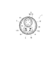
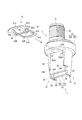
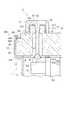
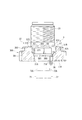
図1及び図2には物理量測定装置の外観が示されている。図3には物理量測定装置の平面が示されている。図4には物理量測定装置の概略構成が示されている。図5には物理量測定装置の断面が示されている。
図1から図5において、物理量測定装置は、円筒状のケース1と、ケース1の一方の開口端に設けられた継手2と、ケース1の他方の開口端に設けられた蓋部材3と、ケース1の内部に配置された測定機構4と、蓋部材3に着脱自在に設けられたキャップ部材5とを備えている。
Embodiments of the present invention will be described with reference to the drawings.
[First Embodiment]
A first embodiment is shown in FIGS.
1 to 5 show the overall configuration of the physical quantity measuring device according to the first embodiment. The physical quantity measuring device of the present embodiment is used in, for example, a ship.
1 and 2 show the appearance of the physical quantity measuring device. FIG. 3 shows a plane of the physical quantity measuring device. FIG. 4 shows a schematic configuration of the physical quantity measuring apparatus. FIG. 5 shows a cross section of the physical quantity measuring device.
1 to 5, the physical quantity measuring device includes a
ケース1は、金属製の円筒部材を加工して形成されたもので、本体部11と、本体部11の他方側に一体形成され蓋部材3を嵌合するための嵌合リング部12とを有する。
嵌合リング部12の直径は、本体部11の直径より大きい。本体部11と嵌合リング部12との間には段差部13がケース径方向に延びて形成されている。
継手2は、被測定流体を導入する導入孔2Aが形成される軸部21と、軸部21の中央部分から径方向に延びて形成されたフランジ部22とを有する金属製部材である。
軸部21の一端部は、図示しない被取付部に螺合されるねじ部23である。
The
The diameter of the
The joint 2 is a metal member having a
One end portion of the
図4及び図5に示される通り、測定機構4は、継手2の軸部21の他端部に設けられ被測定流体の圧力を検出する検出部6と、検出部6から離れて配置された回路基板7と、回路基板7に接続された信号伝達部材8と、蓋部材3に設けられ回路基板7を保持するホルダ9と、を有する。
検出部6は、軸部21の他端部に接合される筒体部61の一端側にダイアフラム62が一体に形成された金属製部材である。
このダイアフラム62には図示しない歪みゲージが形成されており、この歪みゲージによって、導入孔2Aから導入された被測定流体の圧力を検出するようにされている。
As shown in FIGS. 4 and 5, the
The
A strain gauge (not shown) is formed in the
回路基板7は、基板本体70と、基板本体70にそれぞれ設けられた電子回路部71と電子調整部72とを有する。
基板本体70は、正面矩形状の板部材であり、その正面には図示しない配線パターンが形成されている。
本実施形態では、基板本体70は、互いに平行に配置された第一基板701と第二基板702とを備え、これらの第一基板701と第二基板702との間が連結体73で連結されている。
電子回路部71は、検出部6からの検出信号を受信するものであり、基板本体70の正面に設けられている。なお、背面側に配置された基板本体70にも図示しない電子回路部が設けられている。検出部6の歪みゲージと電子回路部71とは図示しない電線等で電気的に接続されている。
The
The
In the present embodiment, the
The
電子調整部72は、電子回路部71を調整するものであり、基板本体70の正面に2つ設けられている。本実施形態では、図4で左側に図示する1つの電子調整部72は、出力電圧を調整するスパン調整用であり、図4で右側に図示する残り1つの電子調整部72は、ゼロ調整用である。
これらの電子調整部72は、それぞれ、蓋部材3に近接する位置にトリマとして機能する被操作部72Aが設けられている。被操作部72Aを図示しないドライバー等の工具で回動あるいは押圧することで、調整が可能となる。
信号伝達部材8は、円筒部材80と、円筒部材80に設けられた複数のターミナル端子81とを有する。ターミナル端子81は図示しない電線等によって回路基板7に電気的に接続されている。
Two
Each of these
The
図4及び図5において、蓋部材3は、合成樹脂製であり、かつ、蓋本体30と、蓋本体30のうちケース1の内部に向けて突出して設けられた支持部31と、蓋本体30の支持部31とは反対側の面にそれぞれ設けられた段部32及び筒状部33とを備えている。
蓋本体30は、ケース1の内部に向く底面3Aが形成された大径部301と、大径部301の底面3Aとは反対側の面に一体形成される小径部302とを有する。
支持部31は、大径部301の底面3Aからケース1の内部に向けて突出した長尺状部材である。なお、ホルダ9を蓋本体30に装着する際に、ターミナル端子81に接続された図示しない電線等が邪魔にならないようにするために、蓋本体30の底面3Aにガイド溝Gを形成してもよい(図6及び図7の想像線参照)。
4 and 5, the
The
The
段部32は、蓋本体30の底面3Aとは反対側に位置する外面から突出して形成されている。段部32は、平面長円状に形成されており、図4中の左右両側部には、それぞれ操作孔32Aが並んで形成されている。
これらの操作孔32Aのうち左側に配置された操作孔32Aは、スパン調整用の電子調整部72の被操作部72Aを図示しないドライバー等の工具で操作するために用いられる。右側に配置された操作孔32Aは、ゼロ調整用の電子調整部72の被操作部72Aを図示しないドライバー等の工具で操作するために用いられる。
ドライバー等の工具での被操作部72Aの操作を容易にするために、操作孔32Aの直下に被操作部72Aが位置する。
筒状部33は、段部32に隣接して配置されるものであり、その内周面は、円筒部材80を取り付ける取付孔33Aとされている。筒状部33の外周面には、雄ねじ部が形成されている。
The
Of these operation holes 32A, the
In order to facilitate the operation of the operated
The
図6から図9に基づいて、回路基板7を蓋部材3に支持するための構成を説明する。
図6には、回路基板7が蓋部材3に支持される全体構成が示されている。図7には、ホルダを蓋部材に装着する状態が示されている。図8には、支持部31の要部が示されている。
図4から図7において、支持部31は、大径部301の底面3Aの外周縁のうち互いに対向する2箇所に配置されている。
A configuration for supporting the
FIG. 6 shows an overall configuration in which the
4 to 7, the
支持部31は、互いに対向する内面がそれぞれ平行とされた基部34と、基部34の内面にそれぞれ設けられた一対の支持突起部35とを備えている。
支持突起部35は、第一基板701と第二基板702とをそれぞれ支持するものであり、基部34の長手方向(支持部突出方向)に沿って3本設けられている。このうち、基部34の中央部に配置された支持突起部35と一方の端縁に配置された支持突起部35とが対となって第一基板701を支持し、中央部に配置された支持突起部35と他方の端縁に配置された支持突起部35とが対となって第二基板702を支持する。
The
The support protrusions 35 support the
基部34の中央部と一方の端縁とに配置された支持突起部35の第一基板701のうち互いに反対側の2つの平面の側縁が一対の第一支持面351とされ、これらの第一支持面351の端縁を接続する基部34の内面が第一基板701の側面部70Aと対向する第二支持面342とされる。
同様に、基部34の中央部と他方の端縁とに配置された支持突起部35の第二基板702のうち互いに反対側の2つの平面の端縁が一対の第一支持面351とされ、これらの第一支持面351の端縁を接続する基部34の内面が第二基板702の側面部70Aと対向する第二支持面342とされる。
本実施形態では、一対の第一支持面351と第二支持面342とから第一基板701を支持する支持溝34Aが構成される。
Side edges of two planes opposite to each other in the
Similarly, the edge of two planes on the opposite sides of the
In the present embodiment, a
基部34の中央部に配置された支持突起部35と一方の端縁に配置された支持突起部35の間には、第一基板701の離反を阻止する爪部36が設けられている。なお、一対の支持部31のうち一方の支持部31にのみ爪部36が図示されているが、他方の支持部31にも同様構造の爪部36が設けられている。
爪部36は、基部34の先端部において突出するように形成されている。
なお、底面3Aの平面内において互いに対向する支持部31の中心部同士を結ぶ線分は、底面3Aの円中心を通る仮想線に対してオフセットしている。しかも、基部34は、その外面がケース1の内周面に沿った円弧状に形成されるとともに、底面3Aから先端にかけて先窄みとなるような勾配を有する。そのため、第二基板702を支持する他方の端縁の支持突起部35は第一基板701を支持する一方の端縁の支持突起部35より長手方向の長さが短くなり、第二基板702の端部が露出される。そのため、中央部に配置された支持突起部35と他方の端縁に配置された支持突起部35の間には、爪部36が設けられていない。ここで、基部34の外面において、底面3Aから先端に向けて先窄みの勾配をつけたのは、支持部31を合成樹脂で成形する際に必要であり、かつ、蓋本体30をケース1に挿入しやすくするためである。
A
The
In addition, the line segment which connects the center part of the
図4から図7、図9に基づいてホルダ9の構成を説明する。図9は、ホルダが蓋部材3に取り付けられた状態が示されている。
これらの図において、ホルダ9は、基板平面が底面3Aに対して直交するように回路基板7を保持するための金属製部材である。
ホルダ9は、蓋部材3の底面3Aに対向する平面部91と、平面部91に設けられ第二基板702を係止する係止片部92とを有する。
平面部91は、第一板部91Aと、第一板部91Aに一体形成された第二板部91Bとを有する。
The structure of the
In these drawings, the
The
The
第一板部91Aは、ケース1の段差部13と蓋部材3の底面3Aとの間に挟持されるものであり、その外形形状は嵌合リング部12の内周面に対応する。
第一板部91Aの円弧を構成する外面とは反対側の直線部は、支持部31の側面に当接する。第一板部91Aが支持部31の側面に当接することで、ホルダ9が蓋部材3に対して位置決めされる(図6,7参照)。
第二板部91Bは、一対の支持部31の間であって、蓋部材3の底面3Aと第一基板701及び第二基板702との間に挿通される(図7参照)。
第二板部91Bは、2つの窓部91C,91Dを有し、第一板部91Aとは反対側の端部91Eは円弧状とされる。
窓部91Cは、ターミナル端子81と回路基板7とを電気的に接続するための電線等を挿通するためのスペースである。窓部91Dは、操作孔32Aから被操作部72Aをドライバー等の工具で操作する際に、当該工具との干渉を避けるためのスペースである。
The
The linear portion opposite to the outer surface that forms the arc of the
The
The
The
図9に示される通り、第二板部91Bの端部91Eは、ケース1の段差部13と蓋部材3の底面3Aとの間に挟持されており、その外形形状は嵌合リング部12の内周面に対応する。
また、ケース1の嵌合リング部12の先端は、かしめられており、蓋本体30とホルダ9の平面部91とが固定される。ここで、本実施形態でのかしめは、全周に渡って連続して行われる全周かしめで行われるが、所定の数カ所で行われる数点かしめで行ってもよい。なお、第一板部91Aと第二板部91Bの端部91Eとは、ケース1の段差部13と蓋部材3の底面3Aとの間に挟持される部分があれば、その外形形状が円弧状に限定されるものではなく、例えば、台形の上辺のような形状であってもよい。
図4から図7において、係止片部92は、第一板部91Aに一体に形成された立上片部92Aと、立上片部92Aに一体に形成され第二基板702に形成された係止孔702Aに係止される係止爪92Bとを有する。係止孔702Aと係止爪92Bとは図示しない半田で固定されている。
本実施形態では、係止孔702Aは、第二基板702のうち蓋部材3の底面3Aに近接した位置(図5及び図6の上端部)に左右2つ並んで形成されている。係止孔702Aの数に応じて、立上片部92Aも2つ係止片部92に形成されている。
As shown in FIG. 9, the
Moreover, the front-end | tip of the
4 to 7, the
In the present embodiment, two locking
図3〜5,10〜12に基づいてキャップ部材5の構成を説明する。図10から図12はキャップ部材5の詳細な構造が示されている。
これらの図において、キャップ部材5は、段部32に形成された2つの操作孔32Aに着脱自在に取り付けられる2つのキャップ本体部51と、これらのキャップ本体部51を連結する連結部52とを備えている。連結部52には、弾性を有する合成樹脂製の線状紛失防止部材53の一端が接続され、線状紛失防止部材53の他端が蓋本体30に係合されている。
キャップ部材5には、筒状部33と対向する外壁面において、筒状部33の外周形状に沿った凹部5Aが形成されている。
本実施形態では、キャップ部材5を構成する2つのキャップ本体部51と連結部52とがゴムや合成樹脂から一体に形成されている。
The configuration of the
In these drawings, the
The
In this embodiment, the two cap main-
キャップ本体部51は、段部32の外周面に内周が係合される外壁面部511と、操作孔32Aの内周面に外周が係合される内壁面部512と、外壁面部511と内壁面部512との基端が接続された天板部513とを備えている。
段部32の外周には、周方向に沿って複数の凸部320が形成されている。外壁面部511の内周面には凸部320の先端が当接している。凸部320の先端が外壁面部511の内周面に当接することで、防水性が向上する。なお、本実施形態では、外壁面部511の内周面には凸部320と係合する溝部51Aが周方向に沿って形成されている構成であってもよい(図11及び図12の想像線参照)。
内壁面部512は、所定長さに渡って操作孔32Aを圧接する。
The cap
A plurality of
The inner
天板部513には、被操作部72Aを区別するための区別標識51S,51Zが形成されている。本実施形態では、図中、左側に配置された操作孔32Aは、スパン調整用の電子調整部72の被操作部72Aを操作するものであるため、区別標識51Sとして「S」の記号が印字される。右側に配置された操作孔32Aは、ゼロ調整用の電子調整部72の被操作部72Aを操作するものであるため、区別標識51Zとして「Z」の記号が印字される(図3,4,10参照)。なお、本実施形態では、区別標識51S,51Zは異なる記号を付すことに限定されるものではなく、例えば、文字を形成したり、色分けしたりするものでもよい。
The
連結部52は、天板部513と同一面上に一体形成された連結板部521と、外壁面部511と同一面上に一体形成された連結壁部522とを有する。
連結板部521には線状紛失防止部材53の一端が接続されている。
線状紛失防止部材53は、弾性を有する合成樹脂製の紐状体であり、その他端は、段部32において2つの操作孔32Aの間に形成された孔部32Bに挿通されている。
孔部32Bは、蓋本体30に形成され底面3Aに開口する大径部32B1と、段部32に形成され段部32の平面に開口する小径部32B2とを有し、大径部32B1と小径部との間は段差部32B3とされている。線状紛失防止部材53は、孔部32Bの段差部32B3に係合可能とされている。
線状紛失防止部材53の長さは、キャップ部材5を外して抜止部530が孔部32Bの段差部32B3に係合された状態において、操作孔32Aにドライバー等の工具を挿通してもキャップ部材5が邪魔にならない長さに設定される。そのため、キャップ部材5が段部32に装着された状態では、抜止部530は孔部32Bから離れた位置にある。
抜止部530は、線状紛失防止部材53の他端に形成された先割部531と、先割部531の間に設けられた接着剤532とを有する。接着剤532は瞬間接着剤やモールド剤、その他を用いることができる。
The connecting
One end of a linear
The linear
The
The length of the linear
The retaining
接着剤532は、先割部531を、その先端間の寸法が小径部32B2の内径寸法より大きく維持させるものである(図11及び図12参照)。
なお、本実施形態では、先割部531の形状は、適宜変更できるものであり、図11及び図12に示される通り、V字状に形成されるものの他、U字状に形成されるものや、矩形状に形成されるものでもよい。さらに、図11及び図12に示される通り、線状紛失防止部材53の他端部に1つのスリットを形成して2つに分割するものの他、3つのスリットを形成して3つに分割するものや、2つのスリットを交差するように形成して4つに分割するものでもよい。
The adhesive 532 maintains the
In addition, in this embodiment, the shape of the front split
次に、本実施形態にかかる物理量測定装置の製造方法について説明する。
[検出部設置工程]
継手2の軸部21に検出部6を溶接等で取り付け、継手2にケース1の一方の開口端を溶接等で接合する。
[蓋部材組付工程]
蓋部材3の筒状部33に信号伝達部材8の円筒部材80を取り付けるとともに、蓋部材3にキャップ部材5を装着する。
蓋部材3にキャップ部材5を装着するため、まず、線状紛失防止部材53を他端が蓋部材3の孔部32Bの底面側の開口端を超えるまで挿通する。ここで、キャップ部材5の連結部52と線状紛失防止部材53とは予め一体に形成されている。なお、本実施形態では、キャップ部材5の連結部52と線状紛失防止部材53の一端とを接着剤等で接続したものでもよい。
その後、他端に抜止部530を形成する。
Next, a method for manufacturing the physical quantity measuring device according to the present embodiment will be described.
[Detector installation process]
The
[Cover member assembly process]
The
In order to attach the
Thereafter, a retaining
抜止部530を形成するために、線状紛失防止部材53を孔部32Bに挿通した後に、あるいは、挿通する前に、線状紛失防止部材53の他端にスリットを形成する。そして、線状紛失防止部材53の他端に形成されたスリットの先端を開いて先割部531を形成し、先割部531の間に接着剤532を塗布する。接着剤532が硬化した状態では、先割部531の先割れの状態が維持されるので、線状紛失防止部材53の他端に抜止部530が形成されることになる。
蓋部材組付工程では、キャップ部材5のキャップ本体部51を段部32に形成された2つの操作孔32Aに装着しておく。この状態では、抜止部530は孔部32Bから離れた位置にある(図11参照)。
In order to form the retaining
In the lid member assembling step, the cap
[回路基板のケース内への設置工程]
次に、電子回路部71と電子調整部72とが設けられた基板本体70を蓋部材3に取り付ける。そのため、基板本体70の第一基板701と第二基板702を蓋部材3の支持突起部35に形成された支持溝34Aに沿って蓋本体30に向けて押し込む。ここで、第一基板701を押し込む際に、互いに対向する爪部36を押し広げる。第一基板701が蓋本体30に最も押し込まれた状態では、爪部36がそれぞれ設けられた支持部31の弾性力によって互いに近接し、これらの爪部36で第一基板701の端部が支持された状態となる。
[Installation process of circuit board in case]
Next, the
第一基板701が爪部36で支持された状態では、基板本体70と蓋本体30の底面3Aとの間に隙間があるので、この隙間にホルダ9を差し込み(図7参照)、第一板部91Aを支持部31の側面に当接させ、かつ、係止片部92を係止孔702Aに挿通して第二基板702を係止する。係止片部92と係止孔702Aとの間を半田つけする。
回路基板7が蓋部材3に支持された状態で、回路基板7をケース1の内部に配置する。本実施形態では、蓋部材3、回路基板7及びホルダ9の形状を同じにしてユニット化しておく。
なお、検出部6と回路基板7との間、並びに、回路基板7と信号伝達部材8との間の電線を用いた接続作業は、適宜なタイミング、例えば、検出部設置工程の前で実施する。
In the state where the
With the
In addition, the connection operation | work using the electric wire between the
[接合工程]
蓋部材3の蓋本体30をケース1の他方の開口端に接合する。そのため、回路基板7が支持された蓋部材3をケース1の嵌合リング部12に嵌合する。すると、ホルダ9がケース1の段差部13と蓋本体30とで挟持されるので、ホルダ9に係止された回路基板7がケース1の内部で動くことがない。さらに、ホルダ9がケース1に電気的に接続されることになる。
その後、嵌合リング部12の先端をかしめることで、蓋本体30とホルダ9の平面部91とが固定される。
[Jointing process]
The
Thereafter, the
このように製造された物理量測定装置を、被取付部に取り付けた直後、あるいは、所定の運転を実施した後に、電子調整部72を調整することがある。
電子調整部72の調整のため、キャップ部材5を持って引っ張る。これにより、キャップ本体部51が操作孔32Aから外れて開口される。キャップ部材5を引っ張る力が大きくても、線状紛失防止部材53の他端に抜止部530が形成されているため、この抜止部530が蓋本体30の孔部32Bの段差部32B3に係合するため、線状紛失防止部材53が抜けることがない。なお、線状紛失防止部材53が所定の長さを有するので、キャップ本体部51が電子調整部72の操作に邪魔になることがない。
The
In order to adjust the
開放された2つの操作孔32Aのうち操作したい電子調整部72に対応する操作孔32Aにドライバー等の工具を挿通し、被操作部72Aを操作する。
操作対象になる電子調整部72は、キャップ本体部51に設けられた区別標識51S,51Zを見て確認する。
取り外した一方のキャップ本体部51は連結部52で他方のキャップ本体部51と連結されているため、双方のキャップ本体部51が互いに離れることがない。
電子調整部72での調整作業が終了したら、開放した操作孔32Aをキャップ本体部51で塞ぐ。
A tool such as a screwdriver is inserted into the
The
Since the removed
When the adjustment work in the
従って、第1実施形態では、次の効果を奏することができる。
(1)電子回路部71及び電子調整部72を有する回路基板7をケース1の内部に配置し、回路基板7に接続される信号伝達部材8を蓋部材3の取付孔33Aに取り付け、電子調整部72の複数の被操作部72Aに応じて設けられた操作孔32Aを蓋部材3に形成し、操作孔32Aを閉塞するキャップ部材5を蓋部材3に設けた。電子調整部72を調整する際に使用する操作孔32Aを、複数のキャップ本体部51を連結部52で連結してなる簡易な構成のキャップ部材5で容易に開閉した。操作孔32Aを信号伝達部材8が設けられる取付孔33Aとは別に設けることで、取付孔33Aに取り付けられた信号伝達部材8が他の接続部材に接続されていても、電子調整部72の調整が行える。
Therefore, in the first embodiment, the following effects can be achieved.
(1) The
(2)連結部52に弾性の線状紛失防止部材53の一端を一体成形や接続等し、線状紛失防止部材53の他端を蓋部材3の孔部32Bの段差部32B2に係合した。そのため、キャップ部材5が蓋部材3から外れることがないので、キャップ部材5の閉め忘れを防止できる。さらに、線状紛失防止部材53が弾性であるため、電子調整部72を調整する際に、キャップ部材5を操作孔32Aから離れた位置に置くことができるから、電子調整部72の調整作業を容易に行える。
(2) One end of the elastic linear
(3)蓋本体30より突出した段部32に操作孔32Aを形成し、かつ、キャップ本体部51の内壁面部512を操作孔32Aの内周面に係合させるとともに、外壁面部511を段部32の外周面に係合させるので、操作孔32Aを通じてのケース1の内部への水の浸入を確実に防止することができる。
(3) The
(4)線状紛失防止部材53を、段部32の隣合う操作孔32Aの間に位置する孔部32Bに挿通し、かつ、その一端をキャップ部材5の中央に位置する連結板部521に一体成形や接着剤で接続等させることで、操作孔32Aの間のスペースを線状紛失防止部材53が挿通するスペースとして有効利用できる。そのため、装置をコンパクトなものにできる。
(4) The linear
(5)線状紛失防止部材53の他端に抜止部530を形成したので、キャップ本体部51が蓋部材3から抜けることを確実に防止できる。
(5) Since the retaining
(6)抜止部530を、線状紛失防止部材53の他端にスリットを形成してなる先割部531と、先割部531の間に設けられた接着剤532とを有する構成としたので、抜止部530を簡易に形成することができる。
(6) Since the retaining
(7)内部に信号伝達部材8が設けられた筒状部33を段部32に隣接して配置し、筒状部33の外周形状と沿った凹部5Aをキャップ部材5に形成したので、筒状部33の外周形状に凹部5Aを合わせることで、キャップ部材5を左右間違えることなく、操作孔32Aに装着することができる。
(7) Since the
(8)キャップ部材5の天板部513に、被操作部72Aを区別するための区別標識51S,51Zを形成したので、キャップ部材5を外して被操作部72Aを操作する際に、操作対象を間違うことを防止できる。
(8) Since the identification marks 51S and 51Z for distinguishing the operated
(9)蓋部材3にキャップ部材5を装着する際に、線状紛失防止部材53を他端が孔部32Bの底面側の開口端を超えるまで挿通し、その後、線状紛失防止部材53の他端に抜止部530を形成したので、物理量測定装置を効率的に製造することができる。
(9) When attaching the
(10)検出部6で検出された信号を受信する板状の回路基板7をケース1の内部に収納し、回路基板7を基板平面が蓋部材3の底面3Aに対して交差するようにホルダ9で保持し、ホルダ9を蓋部材3に設け、蓋部材3を、蓋本体30の底面3Aからケース1の内部に向けて突出した長尺状の支持部31を備えて構成した。支持部31を、回路基板7の互いに反対側に位置する側面部70Aを長手方向に沿ってそれぞれ支持する一対の支持突起部35を有し、ホルダ9を、回路基板7の第二基板702を係止する係止片部92を有する構成とした。そのため、回路基板7を検出部側の部材と接合することを要しないから、物理量測定装置の組立を容易に行うことができる。しかも、回路基板7の側面部70Aを長手方向に沿って支持突起部35で支持しているので、底面3Aに対して回路基板7を正確に位置決めすることができる。その上、蓋部材3にホルダ9を設け、ホルダ9で回路基板7を係止するので、回路基板7が蓋部材3に対して動くことがなく、回路基板7が蓋部材3に対して確実に保持されることになる。
(10) A plate-
(11)支持部31を、支持突起部35にそれぞれ設けられ回路基板7の底面3Aからの離反を阻止する爪部36を有し、ホルダ9を、蓋部材3の底面3Aに対向する平面部91を有する構成とした。そのため、回路基板7の支持突起部35からの抜け止めが爪部36で行われるので、回路基板7の蓋部材3に対する動きが規制されることになり、回路基板7が蓋部材3に対してより確実に保持されることになる。
(11) The
(12)ホルダ9の周縁部を、蓋本体30とケース1とに挟持される構成としたので、ホルダ9の蓋部材3への取付を容易かつ確実に行える。
(12) Since the periphery of the
(13)ケース1をかしめて、蓋本体30とホルダ9の平面部91を固定したので、回路基板7を安定して蓋部材3に支持することができるだけでなく、装置の組立作業が容易となる。
(13) Since the
(14)ケース1とホルダ9とがそれぞれ金属製であり、蓋部材3が合成樹脂製であるため、回路基板7のアースを容易にとることができる。
(14) Since the
(15)基板本体70を、第一基板701と、第二基板702との2枚を互いに平行に配置して構成したから、圧力の検出に必要な電子部品を第一基板701と第二基板702とに分けて配置できる。そのため、1枚の基板に電子部品を配置する場合に比べて、物理量測定装置のケース1の軸方向の長さ寸法を小さなものにできる。
(15) Since the substrate
(16)係止片部92を、第二基板702に形成された係止孔702Aに係止される係止爪92Bを有する構成としたので、第二基板702のホルダ9への支持を容易に行えるだけでなく、回路基板7がホルダ9の平面部91の基板平面内で動くことがない。
(16) Since the locking
(17)係止孔702Aを、第二基板702の底面3Aに近接した位置に形成したから、係止片部92を短くすることが可能となり、係止片部92の破損等を少なくできる。
(17) Since the
(18)一対の支持突起部35の互いに対向する面を第一基板701及び第二基板702の平面端縁とそれぞれ対向する一対の第一支持面351とし、第一支持面351の端縁を接続する面を第一基板701及び第二基板702の側面部70Aと対向する第二支持面342とし、2つの第一支持面351と第二支持面342とから第一基板701と第二基板702とをそれぞれ支持するコ字状の支持溝34Aを構成した。そのため、これらのコ字状の支持溝34Aで第一基板701と第二基板702とをそれぞれ3方向から確実に支持することができる。
(18) The surfaces of the pair of
(19)蓋部材3、回路基板7及びホルダ9の形状を同じにしてユニット化したので、部品点数が減少して製造コストを抑えることができる。
(19) Since the
[第2実施形態]
次に、本発明の第2実施形態を図13から図15に基づいて説明する。
第2実施形態は、蓋部材及びキャップ部材の構成が第1実施形態と異なるもので、他の構成は第1実施形態と同じである。ここで、第2実施形態の説明において、第1実施形態と同一の構成要素は同一符号を付して説明を省略する。
図13から図15には、第2実施形態の要部が示されている。なお、これらの図において、信号伝達部材の図示は省略されている。
図13から図15において、蓋部材37は、第1実施形態のケース1に取り付けられるものであり、操作孔37Aが底部に形成された窪部370を有する。
第2実施形態の操作孔37Aは、第1実施形態の2つの操作孔32Aを連続させて1つの大きな開口面積の孔としたものである。ケース1の内部であって操作孔37Aの近傍に2つの電子調整部72が配置されていることは、第1実施形態と同じである。
[Second Embodiment]
Next, a second embodiment of the present invention will be described with reference to FIGS.
In the second embodiment, the configuration of the lid member and the cap member is different from that of the first embodiment, and other configurations are the same as those of the first embodiment. Here, in description of 2nd Embodiment, the component same as 1st Embodiment attaches | subjects the same code | symbol, and abbreviate | omits description.
The principal part of 2nd Embodiment is shown by FIGS. 13-15. In these drawings, the signal transmission member is not shown.
13 to 15, the
The
キャップ部材5は、窪部370に着脱自在に取り付けられ電子調整部72の被操作部72Aに対応する位置に配置される2つのキャップ本体部57と、これらのキャップ本体部57を連結する連結部58とを備えている。
キャップ本体部57は、窪部370の内周面に外面が係止される外壁面部571と、外壁面部571の基端が接続された天板部572とを備える。
連結部58は、天板部572と同一面上に一体に形成された連結板部582と、連結板部582に基端が接続され外壁面部571と一体に形成された連結壁面部581とを有する。連結壁面部581の下面には補強用のリブ580が設けられている。
天板部572及び連結板部582は、蓋部材37の外面からほぼ面一といえる短い寸法だけ突出している。天板部572及び連結板部582の外周縁は、蓋部材37の外面と連続する傾斜面57Aを有する。
なお、本実施形態でも、被操作部72Aを区別するための区別標識(図示せず)が天板部572に形成されている。
The
The cap
The connecting
The
Also in this embodiment, a distinguishing mark (not shown) for distinguishing the operated
外壁面部571の先端部には線状紛失防止部材77の一端が接続されている。
線状紛失防止部材77は、キャップ本体部57及び連結部58に射出成形等で一体に形成され、あるいは、キャップ本体部57に接着剤等で接着固定されている。
線状紛失防止部材77は、蓋部材37の底面3Aに係止される係止片部77Aと、係止片部77Aに一体形成され外壁面部571と接続された帯状部77Bとを有する。
帯状部77Bは、途中で折り曲げて形成されている。
One end of a linear
The linear
The linear
The belt-
第2実施形態では、第1実施形態の(1)(2)(8)(10)〜(19)と同様の効果を奏することができる他、次の効果を奏することができる。
(20)キャップ本体部57を、蓋部材37の窪部370の内周面に外面が係合される外壁面部571と外壁面部571の基端が接続された天板部572とを備えて構成し、連結部58を、天板部572と一体に形成された連結板部582と連結板部582に基端が接続され外壁面部571と一体に形成された連結壁面部581とを有する構成とした。これにより、蓋部材37の窪部370の内周と外壁面部571及び連結壁面部581との外周とが密閉することで、高い防水効果を得ることができる。
In the second embodiment, the same effects as (1), (2), (8), (10) to (19) of the first embodiment can be obtained, and the following effects can be obtained.
(20) The cap
(21)線状紛失防止部材77の一端が外壁面部571の先端に接続されているので、キャップ部材5を外した際に、操作孔37Aを大きく開放することができるため、被操作部72Aの操作を容易に行うことができる。
(21) Since one end of the linear
(22)天板部572及び連結板部582の外周縁は蓋部材37の外面と連続する傾斜面57Aを有するから、キャップ部材5の蓋部材37からの出っ張りが目立たない。そのため、蓋部材37に装着された状態のキャップ部材5が邪魔にならない。
(22) Since the outer peripheral edges of the
次に、本発明の第3実施形態を図16から図18に基づいて説明する。
第3実施形態は、蓋部材の構成が第1実施形態と異なるもので、他の構成は第1実施形態と同じである。ここで、第3実施形態の説明において、第1実施形態と同一の構成要素は同一符号を付して説明を省略する。
図16から図18には、第3実施形態の要部が示されている。なお、これらの図において、信号伝達部材の図示は省略されている。
図16から図18において、蓋本体30の底面3Aとは反対側の外面には円筒状の段部38と、筒状部33の基部の周囲を覆う板部39とがそれぞれ形成されている。
板部39の厚さ寸法は、筒状部33の軸方向寸法より短い。
板部39の平面形状は、段部38と対向する部分が中央部を除いて直線状に形成され、この直線状に形成された部分以外は蓋本体30の外周縁に沿って円弧状とされる。
第3実施形態では、2つの操作孔32Aのうち1つの操作孔32Aが段部38を貫通して形成され、残り1つの操作孔32Aが蓋本体30に形成されている(図17及び図18参照)。段部38に形成された操作孔32Aに対応する被操作部72Aを有する電子調整部72は、特に、防水が必要な電子部品である。
Next, a third embodiment of the present invention will be described with reference to FIGS.
In the third embodiment, the configuration of the lid member is different from that of the first embodiment, and other configurations are the same as those of the first embodiment. Here, in description of 3rd Embodiment, the component same as 1st Embodiment attaches | subjects the same code | symbol, and abbreviate | omits description.
The principal part of 3rd Embodiment is shown by FIGS. 16-18. In these drawings, the signal transmission member is not shown.
16 to 18, a
The thickness dimension of the
The planar shape of the
In the third embodiment, one
段部38に形成された操作孔32Aには、キャップ本体部59Aが着脱自在に設けられている。
キャップ本体部59Aは、段部38の外周面に内周が係止される外壁面部591と外壁面部591の基端に設けられた天板部592とを有する。
段部38の外周には、周方向に沿って複数の凸部380が形成されている。外壁面部591の内周面には、凸部380の先端が当接している。凸部380の先端が外壁面部591の内周面に当接することで、防水性が向上する。なお、本実施形態では、外壁面部591の内周面には凸部380と係合する溝部590が周方向に沿って形成されている構成であってもよい(図18の想像線参照)。
蓋本体30に形成された操作孔32Aには、キャップ本体部59Bが着脱自在に設けられている。
キャップ本体部59Bは、操作孔32Aの内周面に外面が係止される円錐部593と、円錐部593の基部が接続された天板部594とを有する。円錐部593の外周縁部が操作孔32Aの内周面に接触し、天板部594が蓋本体30に接触することで、防水性が得られる。
天板部594の高さ寸法は、キャップ本体部59Aの高さ寸法より低い。
キャップ本体59A,59Bは、それぞれゴムや合成樹脂から形成されている。
本実施形態では、被操作部72Aを区別するための区別標識(図示せず)がキャップ本体部59A,59Bに形成されている。
A cap
The cap main body portion 59 </ b> A includes an outer
On the outer periphery of the stepped
A cap
The
The height dimension of the
The
In the present embodiment, a distinguishing mark (not shown) for distinguishing the operated
キャップ本体部59Aとキャップ本体部59Bとは、合成樹脂製の連結部59Cで連結されている。
連結部59Cは、キャップ本体部59Aの外壁面部591とキャップ本体部59Bの天板部594とを連結する断面矩形状の合成樹脂製線状部材であり、射出成形等によって、一体に形成、あるいは、接着剤等で接着固定される。
連結部59Cは、蓋本体30の平面に沿って配置されるものであり、キャップ本体部59A,59Bにそれぞれ接続される直線状の端部595と、これらの端部595に接続される中央部596とを有する。
中央部596は、端部595から直角に折れ曲がって形成され板部39の段部38と対向する直線部分に沿って配置された直線部596Aと、直線部596Aと一体形成され筒状部33の外周に沿って配置された曲線部596Bとを有する。
The cap
The connecting
The connecting
The
第3実施形態では、第1実施形態の(1)(3)(8)(10)〜(19)と同様の効果を奏することができる他、次の効果を奏することができる。
(23)2つのキャップ本体部59A,59Bのうち一方のキャップ本体部59Aを、段部38の外周面に内周が係止される外壁面部591と外壁面部591の基端が接続された天板部592とを有する構成とし、他方のキャップ本体部59Bを、操作孔32Aの内周面に外面が係止される円錐部593と円錐部593の基部が接続された天板部594とを有する構成とした。そして、連結部59Cを、キャップ本体部59Aの外壁面部591とキャップ本体部59Bの天板部594とを連結する弾性の線状部材を備えた構成とした。そのため、キャップ本体部59Aを操作孔32Aから外す場合には、キャップ本体部59Bを操作孔32Aに装着することで、一対のキャップ本体部59A,59Bの紛失を防止することができる。防水が必要な操作孔32Aを段部38に形成することで、防水効果を高めることができる。キャップ本体部59A,59Bの形状が異なるので、間違えて操作孔32Aに装着することを防止できる。
In the third embodiment, the same effects as (1), (3), (8), (10) to (19) of the first embodiment can be obtained, and the following effects can be obtained.
(23) One of the two cap
なお、本発明は前述の実施形態に限定されるものではなく、本発明の目的を達成できる範囲での変形、改良等は本発明に含まれるものである。
例えば、前記実施形態では、基板本体70を第一基板701と第二基板702とを備えて構成したが、本発明では、基板本体70を1枚あるいは3枚以上の基板から構成してもよい。
さらに、本発明では、ホルダ9や支持突起部35を必ずしも設けることを要せず、例えば、基板本体70の端部を継手に接合する構成であってもよい。
It should be noted that the present invention is not limited to the above-described embodiments, and modifications, improvements, and the like within the scope that can achieve the object of the present invention are included in the present invention.
For example, in the embodiment, the
Furthermore, in the present invention, it is not always necessary to provide the
前記各実施形態では、電子調整部72をスパン調整用とゼロ調整用との2つとしたが、本発明では、直線性補正用とダンプナ用との2つとしてもよい。
さらに、電子調整部72の数は2つに限定されるものではなく、3つ以上とし、それぞれ被操作部72Aを有するものでもよい。電子調整部72の数は1つであってもよく、この場合、被操作部72Aが複数あればよい。
本発明では、キャップ本体部51,57,59A,59Bの数は被操作部72Aの数に応じるものであり、前記実施形態のように2つに限定されるものではない。
また、前記実施形態では、物理量測定装置として圧力を測定する装置を例示して説明したが、本発明では、これに限定されることはなく、例えば、差圧センサや温度センサにも適用可能である。
In each of the above-described embodiments, two
Further, the number of
In the present invention, the number of the cap
In the above embodiment, an apparatus for measuring pressure has been described as an example of the physical quantity measuring apparatus. However, the present invention is not limited to this, and can be applied to, for example, a differential pressure sensor and a temperature sensor. is there.
第1実施形態では、抜止部530を、線状紛失防止部材53の他端にスリットを形成してなる先割部531と、先割部531の間に設けられた接着剤532とを有する構成としたが、本発明では、線状紛失防止部材53の端部にねじを形成し、このねじにナットを螺合させて抜止部を構成するものでもよい。
第2実施形態では、操作孔37Aを2つ蓋部材37に形成し、キャップ部材を、2つの操作孔37Aにそれぞれ取り付けられるキャップ本体部と、キャップ本体部同士を連結する板状の連結部とを有する構成としてもよい。
第3実施形態では、キャップ本体部59A,59Bの形状が異なるものであったが、本発明では、同じ形状としてもよい。
In the first embodiment, the retaining
In the second embodiment, two
In the third embodiment, the cap
1…ケース、2…継手、3,37…蓋部材、5…キャップ部材、6…検出部、7…回路基板、8…信号伝達部材、9…ホルダ、3A…底面、30…蓋本体、32,38…段部、32A,37A…操作孔、33…筒状部、35…支持突起部、36…爪部、342…第二支持面、34A…支持溝、351…第一支持面、51,57,59A,59B…キャップ本体部、5A…凹部、511…外壁面部、512…内壁面部、51S,51Z…区別標識、521…連結板部、522…連結壁部、53…線状紛失防止部材、530…抜止部、531…先割部、532…接着剤、591…外壁面部、592…天板部、92…係止片部
DESCRIPTION OF
Claims (7)
前記ケースの一方の開口端側に配置され被測定流体の物理量を検出する検出部と、
前記ケースの他方の開口端に取り付けられた蓋部材と、
前記ケースの内部に配置され前記検出部で検出された信号を受信する電子回路部及び前記電子回路部の調整をする電子調整部を有する回路基板と、
前記回路基板に接続されるとともに前記蓋部材に設けられた信号伝達部材とを備え、
前記電子調整部は複数の被操作部を有し、
前記蓋部材には、前記信号伝達部材を取り付ける取付孔と、前記電子調整部を調整する際に使用し前記複数の被操作部をそれぞれ操作可能とした操作孔とがそれぞれ形成され、
前記操作孔を閉塞するキャップ部材が前記蓋部材に設けられ、
前記キャップ部材は、前記操作孔に着脱自在に設けられた複数のキャップ本体部と、これらのキャップ本体部を連結する連結部とを有し、
前記連結部に弾性の線状紛失防止部材の一端が接続され、前記線状紛失防止部材の他端が前記蓋部材に係合され、
前記蓋部材は、前記ケースの内部に向く底面が形成された蓋本体と、前記蓋本体の前記底面とは反対側の面に突出して形成され前記操作孔が形成された段部とを有し、前記段部のうち隣合う前記操作孔の間に前記線状紛失防止部材が挿通される孔部が前記蓋本体及び前記段部に形成され、
前記キャップ本体部は、前記段部の外周面に内周が係合される外壁面部と、前記操作孔の内周面に外周が係合される内壁面部と、前記外壁面部と前記内壁面部との基端が接続された天板部とを備え、
前記連結部は、前記天板部と一体に形成された連結板部を有し、
前記線状紛失防止部材の一端は前記連結板部に接続され、前記線状紛失防止部材の他端は前記孔部に係合される
ことを特徴とする物理量測定装置。 A cylindrical case,
A detector that is disposed on one opening end side of the case and detects a physical quantity of the fluid to be measured;
A lid member attached to the other open end of the case;
An electronic circuit unit disposed inside the case for receiving a signal detected by the detection unit, and a circuit board having an electronic adjustment unit for adjusting the electronic circuit unit;
A signal transmission member connected to the circuit board and provided on the lid member;
The electronic adjustment unit has a plurality of operated parts,
The lid member is formed with an attachment hole for attaching the signal transmission member, and an operation hole that is used when adjusting the electronic adjustment portion, and each of the operated portions can be operated,
A cap member for closing the operation hole is provided on the lid member,
It said cap member is perforated with a plurality of cap body detachably provided in said operation hole and a connecting portion for connecting the cap main body,
One end of an elastic linear loss prevention member is connected to the connecting portion, and the other end of the linear loss prevention member is engaged with the lid member ,
The lid member has a lid body formed with a bottom surface facing the inside of the case, and a stepped portion formed on the surface opposite to the bottom surface of the lid body and formed with the operation hole. , A hole portion through which the linear loss prevention member is inserted between the adjacent operation holes among the step portions is formed in the lid body and the step portion,
The cap body portion includes an outer wall surface portion whose inner periphery is engaged with an outer peripheral surface of the stepped portion, an inner wall surface portion whose outer periphery is engaged with an inner peripheral surface of the operation hole, the outer wall surface portion, and the inner wall surface portion. A base plate to which the base end of the
The connecting portion has a connecting plate portion formed integrally with the top plate portion,
The physical quantity measuring device , wherein one end of the linear loss preventing member is connected to the connecting plate portion, and the other end of the linear loss preventing member is engaged with the hole portion .
前記線状紛失防止部材の他端には、当該他端が前記孔部を通じて前記ケースの内部から外部へ抜けることを防止する抜止部が設けられる
ことを特徴とする物理量測定装置。 The physical quantity measuring device according to claim 1 ,
The physical quantity measuring device, wherein the other end of the linear loss prevention member is provided with a retaining portion that prevents the other end from being pulled out from the inside of the case through the hole.
前記蓋部材は、前記段部に隣接して配置され内部に前記信号伝達部材が設けられた筒状部を備え、
前記キャップ部材には前記筒状部の外周形状と沿った凹部が形成され、
前記天板部には、前記複数の被操作部を区別するための区別標識が形成されている
ことを特徴とする物理量測定装置。 In the physical quantity measuring device according to claim 1 or 2 ,
The lid member includes a cylindrical portion that is disposed adjacent to the stepped portion and in which the signal transmission member is provided,
The cap member is formed with a recess along the outer peripheral shape of the cylindrical portion,
The physical quantity measuring device, wherein a distinction mark for distinguishing the plurality of operated parts is formed on the top plate part.
前記ケースの一方の開口端側に配置され被測定流体の物理量を検出する検出部と、
前記ケースの他方の開口端に取り付けられた蓋部材と、
前記ケースの内部に配置され前記検出部で検出された信号を受信する電子回路部及び前記電子回路部の調整をする電子調整部を有する回路基板と、
前記回路基板に接続されるとともに前記蓋部材に設けられた信号伝達部材とを備え、
前記電子調整部は複数の被操作部を有し、
前記蓋部材には、前記信号伝達部材を取り付ける取付孔と、前記電子調整部を調整する際に使用し前記複数の被操作部をそれぞれ操作可能とした操作孔とがそれぞれ形成され、
前記操作孔を閉塞するキャップ部材が前記蓋部材に設けられ、
前記キャップ部材は、前記操作孔に着脱自在に設けられた複数のキャップ本体部と、これらのキャップ本体部を連結する連結部とを有し、
前記連結部に弾性の線状紛失防止部材の一端が接続され、前記線状紛失防止部材の他端が前記蓋部材に係合され、
前記蓋部材は前記操作孔が底面に形成された窪部を有し、
前記キャップ本体部は、前記窪部の内周面に外面が係合される外壁面部と前記外壁面部の基端が接続された天板部とを備え、
前記連結部は、前記天板部と一体に形成された連結板部と、この連結板部に基端が接続され前記外壁面部と一体に形成された連結壁面部とを有し、
前記線状紛失防止部材の一端は、前記外壁面部の先端に接続され、前記線状紛失防止部材の他端は前記蓋部材に係合される
ことを特徴とする物理量測定装置。 A cylindrical case,
A detector that is disposed on one opening end side of the case and detects a physical quantity of the fluid to be measured;
A lid member attached to the other open end of the case;
An electronic circuit unit disposed inside the case for receiving a signal detected by the detection unit, and a circuit board having an electronic adjustment unit for adjusting the electronic circuit unit;
A signal transmission member connected to the circuit board and provided on the lid member;
The electronic adjustment unit has a plurality of operated parts,
The lid member is formed with an attachment hole for attaching the signal transmission member, and an operation hole that is used when adjusting the electronic adjustment portion, and each of the operated portions can be operated,
A cap member for closing the operation hole is provided on the lid member,
The cap member has a plurality of cap main body portions that are detachably provided in the operation hole, and a connecting portion that connects these cap main body portions,
One end of an elastic linear loss prevention member is connected to the connecting portion, and the other end of the linear loss prevention member is engaged with the lid member,
The lid member has a recess in which the operation hole is formed on the bottom surface,
The cap body portion includes an outer wall surface portion whose outer surface is engaged with an inner peripheral surface of the recess portion, and a top plate portion to which a base end of the outer wall surface portion is connected,
The connecting portion includes a connecting plate portion formed integrally with the top plate portion, and a connecting wall surface portion formed integrally with the outer wall surface portion with a base end connected to the connecting plate portion,
One end of the linear loss prevention member is connected to a tip of the outer wall surface, and the other end of the linear loss prevention member is engaged with the lid member.
前記キャップ部材が前記窪部に設けられた状態において、前記天板部及び連結板部の外周縁は前記蓋部材の前記底面とは反対側に位置する外面と連続する傾斜面を有する
ことを特徴とする物理量測定装置。 The physical quantity measuring device according to claim 4 ,
In the state where the cap member is provided in the recess, the outer peripheral edges of the top plate portion and the connecting plate portion have an inclined surface that is continuous with an outer surface located on the opposite side of the bottom surface of the lid member. A physical quantity measuring device.
前記ケースの一方の開口端側に配置され被測定流体の物理量を検出する検出部と、
前記ケースの他方の開口端に取り付けられた蓋部材と、
前記ケースの内部に配置され前記検出部で検出された信号を受信する電子回路部及び前記電子回路部の調整をする電子調整部を有する回路基板と、
前記回路基板に接続されるとともに前記蓋部材に設けられた信号伝達部材とを備え、
前記電子調整部は複数の被操作部を有し、
前記蓋部材には、前記信号伝達部材を取り付ける取付孔と、前記電子調整部を調整する際に使用し前記複数の被操作部をそれぞれ操作可能とした操作孔とがそれぞれ形成され、
前記操作孔を閉塞するキャップ部材が前記蓋部材に設けられ、
前記キャップ部材は、前記操作孔に着脱自在に設けられた複数のキャップ本体部と、これらのキャップ本体部を連結する連結部とを有し、
前記蓋部材は、底面が形成されるとともに前記操作孔が複数形成された蓋本体と、前記蓋本体の前記底面とは反対側に位置する外面に突出して形成され前記複数の操作孔のうち一部の操作孔が形成された段部とを有し、
前記複数のキャップ本体部のうち一方のキャップ本体部は、前記段部の外周面に内周が係止される外壁面部と前記外壁面部の基端が接続された天板部とを備え、
前記複数のキャップ本体部のうち他方のキャップ本体部は、前記操作孔の内周面に外面が係止される円錐部と前記円錐部の基部が接続された天板部とを備え、
前記連結部は、前記一方のキャップ本体部の外壁面部と前記他方のキャップ本体部の天板部とを連結する弾性の線状部材を備えた
ことを特徴とする物理量測定装置。 A cylindrical case,
A detector that is disposed on one opening end side of the case and detects a physical quantity of the fluid to be measured;
A lid member attached to the other open end of the case;
An electronic circuit unit disposed inside the case for receiving a signal detected by the detection unit, and a circuit board having an electronic adjustment unit for adjusting the electronic circuit unit;
A signal transmission member connected to the circuit board and provided on the lid member;
The electronic adjustment unit has a plurality of operated parts,
The lid member is formed with an attachment hole for attaching the signal transmission member, and an operation hole that is used when adjusting the electronic adjustment portion, and each of the operated portions can be operated,
A cap member for closing the operation hole is provided on the lid member,
The cap member has a plurality of cap main body portions that are detachably provided in the operation hole, and a connecting portion that connects these cap main body portions,
The lid member includes a lid body having a bottom surface and a plurality of the operation holes, and an outer surface located on the opposite side of the lid body from the bottom surface. The lid member includes one of the plurality of operation holes. And a step portion in which an operation hole is formed,
One cap body part of the plurality of cap body parts includes an outer wall surface part whose inner periphery is locked to an outer peripheral surface of the stepped part, and a top plate part to which a base end of the outer wall surface part is connected,
The other cap body portion of the plurality of cap body portions includes a conical portion whose outer surface is locked to an inner peripheral surface of the operation hole, and a top plate portion to which a base portion of the conical portion is connected,
The said connection part was equipped with the elastic linear member which connects the outer wall surface part of said one cap main-body part, and the top-plate part of said other cap main-body part. The physical-quantity measuring apparatus characterized by the above-mentioned.
前記ケースの一方の開口端に前記検出部を設ける検出部設置工程と、
前記信号伝達部材を前記蓋部材に設けるとともに、前記蓋部材に前記キャップ部材を装着する蓋部材組付工程と、
前記蓋部材を前記ケースの他方の開口端に接合する接合工程とを備え、
前記蓋部材組付工程は、前記線状紛失防止部材を前記他端が前記孔部の底面側の開口端を超えるまで挿通し、前記他端に抜止部を形成する
ことを特徴とする物理量測定装置の製造方法。 A method for manufacturing a physical quantity measuring device according to claim 2 ,
A detection unit installation step of providing the detection unit at one open end of the case;
A lid member assembling step of mounting the signal transmission member on the lid member and mounting the cap member on the lid member;
A bonding step of bonding the lid member to the other opening end of the case,
In the lid member assembling step, the linear loss prevention member is inserted until the other end exceeds the opening end on the bottom surface side of the hole portion, and a retaining portion is formed at the other end. Device manufacturing method.
Priority Applications (4)
| Application Number | Priority Date | Filing Date | Title |
|---|---|---|---|
| JP2014063678A JP6093323B2 (en) | 2014-03-26 | 2014-03-26 | Physical quantity measuring apparatus and manufacturing method thereof |
| US14/666,542 US9952114B2 (en) | 2014-03-26 | 2015-03-24 | Physical quantity measuring device and method of manufacturing the same |
| EP15160782.7A EP2927657B1 (en) | 2014-03-26 | 2015-03-25 | Fluid pressure measuring device and method of manufacturing the same |
| TW104109824A TWI674398B (en) | 2014-03-26 | 2015-03-26 | Physical quantity measuring device and method of manufacturing the same |
Applications Claiming Priority (1)
| Application Number | Priority Date | Filing Date | Title |
|---|---|---|---|
| JP2014063678A JP6093323B2 (en) | 2014-03-26 | 2014-03-26 | Physical quantity measuring apparatus and manufacturing method thereof |
Publications (3)
| Publication Number | Publication Date |
|---|---|
| JP2015184259A JP2015184259A (en) | 2015-10-22 |
| JP2015184259A5 JP2015184259A5 (en) | 2016-04-07 |
| JP6093323B2 true JP6093323B2 (en) | 2017-03-08 |
Family
ID=52727021
Family Applications (1)
| Application Number | Title | Priority Date | Filing Date |
|---|---|---|---|
| JP2014063678A Active JP6093323B2 (en) | 2014-03-26 | 2014-03-26 | Physical quantity measuring apparatus and manufacturing method thereof |
Country Status (4)
| Country | Link |
|---|---|
| US (1) | US9952114B2 (en) |
| EP (1) | EP2927657B1 (en) |
| JP (1) | JP6093323B2 (en) |
| TW (1) | TWI674398B (en) |
Families Citing this family (8)
| Publication number | Priority date | Publication date | Assignee | Title |
|---|---|---|---|---|
| JP6483050B2 (en) * | 2016-06-02 | 2019-03-13 | 長野計器株式会社 | Physical quantity measuring device |
| JP6370842B2 (en) * | 2016-06-29 | 2018-08-08 | ファナック株式会社 | Article conveying apparatus provided with temporary storage |
| JP6841794B2 (en) * | 2018-06-26 | 2021-03-10 | 長野計器株式会社 | Physical quantity measuring device and manufacturing method of physical quantity measuring device |
| JP6931343B2 (en) * | 2018-09-25 | 2021-09-01 | 長野計器株式会社 | Physical quantity measuring device |
| JP6964063B2 (en) * | 2018-11-28 | 2021-11-10 | 長野計器株式会社 | Sensor assembly and physical quantity measuring device |
| JP7295079B2 (en) * | 2020-03-26 | 2023-06-20 | 長野計器株式会社 | Physical quantity measuring device |
| US11513021B2 (en) | 2020-03-26 | 2022-11-29 | Nagano Keiki Co., Ltd. | Physical quantity measuring device with improved cap sealing |
| KR102815242B1 (en) * | 2024-05-22 | 2025-05-30 | 월드코어(주) | Pressure transmitter using lazer weld |
Family Cites Families (17)
| Publication number | Priority date | Publication date | Assignee | Title |
|---|---|---|---|---|
| IT206726Z2 (en) * | 1985-09-17 | 1987-10-01 | Marelli Autronica | PRESSURE METER DEVICE |
| JPH0235927B2 (en) | 1985-09-24 | 1990-08-14 | Kajima Corp | HEKIMENTORITSUKEKIGUNOKIMITSUSHIKENKI |
| US4756193A (en) * | 1987-09-11 | 1988-07-12 | Delco Electronics Corporation | Pressure sensor |
| US4967047A (en) * | 1989-01-09 | 1990-10-30 | Acustar, Inc. | Switch with post-assembly calibration access |
| JP2551860B2 (en) | 1990-09-25 | 1996-11-06 | 東ソー・アクゾ株式会社 | Metal complex for thin film formation |
| JP2540967Y2 (en) * | 1991-05-29 | 1997-07-09 | 株式会社 不二工機 | Pressure sensor |
| JP3708691B2 (en) | 1997-10-17 | 2005-10-19 | シーケーディ株式会社 | Pressure detector |
| DE69815801T2 (en) | 1997-12-11 | 2004-05-19 | Nagano Keiki Co., Ltd. | pressure transducer |
| US7367233B2 (en) * | 2004-06-03 | 2008-05-06 | Nagano Keiki Co., Ltd. | Pressure sensor module and pressure detecting device |
| US7252009B2 (en) | 2004-08-27 | 2007-08-07 | Ashcroft-Nagano, Inc. | System and method for pressure measurement |
| JP2006338998A (en) * | 2005-06-01 | 2006-12-14 | Surpass Kogyo Kk | Pressure switch |
| JP2007188835A (en) * | 2006-01-16 | 2007-07-26 | Maruyama Mfg Co Ltd | Protection cap of charging terminal |
| DE102007031980A1 (en) | 2007-07-10 | 2009-01-15 | Robert Bosch Gmbh | Connection unit for a pressure measuring cell |
| DE102009045790A1 (en) | 2009-10-19 | 2011-04-21 | Robert Bosch Gmbh | Pressure sensor, in particular for braking devices |
| DE102010041169A1 (en) | 2010-09-22 | 2012-03-22 | Robert Bosch Gmbh | Pressure sensor, in particular for braking device |
| US9045036B2 (en) | 2010-11-12 | 2015-06-02 | Piolax, Inc. | Cap attaching structure |
| JP6009759B2 (en) * | 2011-11-30 | 2016-10-19 | アンリツインフィビス株式会社 | Cap structure in electronic equipment |
-
2014
- 2014-03-26 JP JP2014063678A patent/JP6093323B2/en active Active
-
2015
- 2015-03-24 US US14/666,542 patent/US9952114B2/en active Active
- 2015-03-25 EP EP15160782.7A patent/EP2927657B1/en active Active
- 2015-03-26 TW TW104109824A patent/TWI674398B/en active
Also Published As
| Publication number | Publication date |
|---|---|
| EP2927657B1 (en) | 2017-10-18 |
| EP2927657A1 (en) | 2015-10-07 |
| US20150276537A1 (en) | 2015-10-01 |
| US9952114B2 (en) | 2018-04-24 |
| TWI674398B (en) | 2019-10-11 |
| TW201602539A (en) | 2016-01-16 |
| JP2015184259A (en) | 2015-10-22 |
Similar Documents
| Publication | Publication Date | Title |
|---|---|---|
| JP6093323B2 (en) | Physical quantity measuring apparatus and manufacturing method thereof | |
| JP4752644B2 (en) | connector | |
| US8210037B2 (en) | Sensor module with a housing which may be mounted on a wall | |
| US10145749B2 (en) | Physical quantity measuring device including a sensor module and a joint for locking the sensor module | |
| CN102570155B (en) | Waterproof connector, waterproof connector assembly method | |
| CN107453116B (en) | Electrical connector with coding function | |
| JP6127009B2 (en) | Physical quantity measuring device | |
| JP2010212136A (en) | Joint connector | |
| KR100577130B1 (en) | Hose for an Electric Cleaner | |
| KR20170042109A (en) | Sensing apparatus | |
| US20140335713A1 (en) | Connector | |
| JP5261521B2 (en) | Assembly method of electrical parts | |
| US10674925B2 (en) | Electrode assemblies for measuring bio-signals | |
| TWI820218B (en) | Physical quantity measuring device | |
| EP3376284A1 (en) | Camera module | |
| JP2011227023A (en) | Gas sensor unit | |
| JP2010232130A (en) | Connection structure for lid with connector | |
| US20240266787A1 (en) | Connector | |
| JP7295079B2 (en) | Physical quantity measuring device | |
| JP5997686B2 (en) | Physical quantity measurement sensor | |
| JP2010232013A (en) | Connection structure of lid with connector | |
| JP2010167890A (en) | Electric part protection member and assembling method |
Legal Events
| Date | Code | Title | Description |
|---|---|---|---|
| A521 | Request for written amendment filed |
Free format text: JAPANESE INTERMEDIATE CODE: A523 Effective date: 20160219 |
|
| A621 | Written request for application examination |
Free format text: JAPANESE INTERMEDIATE CODE: A621 Effective date: 20160219 |
|
| A977 | Report on retrieval |
Free format text: JAPANESE INTERMEDIATE CODE: A971007 Effective date: 20161031 |
|
| A131 | Notification of reasons for refusal |
Free format text: JAPANESE INTERMEDIATE CODE: A131 Effective date: 20161108 |
|
| A521 | Request for written amendment filed |
Free format text: JAPANESE INTERMEDIATE CODE: A523 Effective date: 20161228 |
|
| TRDD | Decision of grant or rejection written | ||
| A01 | Written decision to grant a patent or to grant a registration (utility model) |
Free format text: JAPANESE INTERMEDIATE CODE: A01 Effective date: 20170124 |
|
| A61 | First payment of annual fees (during grant procedure) |
Free format text: JAPANESE INTERMEDIATE CODE: A61 Effective date: 20170210 |
|
| R150 | Certificate of patent or registration of utility model |
Ref document number: 6093323 Country of ref document: JP Free format text: JAPANESE INTERMEDIATE CODE: R150 |
|
| R250 | Receipt of annual fees |
Free format text: JAPANESE INTERMEDIATE CODE: R250 |
|
| R250 | Receipt of annual fees |
Free format text: JAPANESE INTERMEDIATE CODE: R250 |
|
| R250 | Receipt of annual fees |
Free format text: JAPANESE INTERMEDIATE CODE: R250 |
|
| R250 | Receipt of annual fees |
Free format text: JAPANESE INTERMEDIATE CODE: R250 |
|
| R250 | Receipt of annual fees |
Free format text: JAPANESE INTERMEDIATE CODE: R250 |