JP6092532B2 - Chair - Google Patents
Chair Download PDFInfo
- Publication number
- JP6092532B2 JP6092532B2 JP2012147314A JP2012147314A JP6092532B2 JP 6092532 B2 JP6092532 B2 JP 6092532B2 JP 2012147314 A JP2012147314 A JP 2012147314A JP 2012147314 A JP2012147314 A JP 2012147314A JP 6092532 B2 JP6092532 B2 JP 6092532B2
- Authority
- JP
- Japan
- Prior art keywords
- backrest
- vertical
- backrest member
- deformation
- piece
- Prior art date
- Legal status (The legal status is an assumption and is not a legal conclusion. Google has not performed a legal analysis and makes no representation as to the accuracy of the status listed.)
- Expired - Fee Related
Links
Images


Description
本発明は、背凭れフレームの前面側に、可撓性の背当部材を取付けてなる椅子に関する。 The present invention relates to a chair having a flexible backrest member attached to the front side of a backrest frame.
例えば特許文献1および2には、座の後方より起立する背凭れフレームの前面側に、可撓性の背当部材(背板)を取付け、この背当部材を、着座者の背中により後向きに弾性変形させることにより、着座者の背中を快適に支持しうるようにした椅子が開示されている。
For example, in
上記特許文献1および2に記載されている椅子においては、いずれも、背凭れフレームの左右両側部に、背当部材の左右両側部の後面を、上下方向の軸線回りに回動可能に取り付け、背当部材に背中を押し当てた際に、背当部材全体が、両側部の軸を中心として後方に弾性変形しうるようになっている。
そのため、背当部材の中央部は後方に比較的大きく弾性変形するものの、背凭れフレームに軸を介して支持されている背当部材の左右両側部においては、軸を中心として後方へ若干変位するのみで、中央部の変形量に比して小さく、中央部と両側部との弾性変形量に大きな差が生じる。このようになると、背当部材全体を後方に効果的に弾性変形させることができないので、着座者の背中全体を快適に支持することが難しくなる。
また、背当部材における背凭れフレームへの取付部は、背当部材の後面に突設した軸支手段または軸が嵌合される係合部により補強され、その部分の剛性が高くなっているので、背当部材における背凭れフレームへの取付部付近は、特に後方に弾性変形しにくい。
In the chairs described in
Therefore, although the central portion of the backrest member is elastically deformed relatively rearwardly, the left and right side portions of the backrest member supported by the backrest frame via the shaft are slightly displaced rearward about the shaft. As a result, the amount of deformation is small compared to the amount of deformation at the center, and a large difference occurs in the amount of elastic deformation between the center and both sides. If it becomes like this, since the whole backrest member cannot be elastically deformed back effectively, it becomes difficult to support a seated person's back comfortably.
Further, the attachment portion of the backrest member to the backrest frame is reinforced by the shaft support means projecting on the rear surface of the backrest member or the engaging portion into which the shaft is fitted, and the rigidity of the portion is increased. Therefore, the vicinity of the attachment portion of the backrest member to the backrest frame is particularly difficult to elastically deform backward.
本発明は、上記問題点に鑑みてなされたもので、背当部材の左右両側部を後方に弾性変形し易くすることにより、背凭れフレームに対し背当部材全体を後方に効果的に弾性変形しうるようにして、着座者の背中全体がより快適に支持されるようにした椅子を提供することを目的としている。 The present invention has been made in view of the above problems, and by making the left and right sides of the backrest member elastically deformable rearward, the entire backrest member is effectively elastically deformed rearward with respect to the backrest frame. It is an object of the present invention to provide a chair in which the entire back of the seated person is supported more comfortably.
本発明によると、上記課題は、次の各項のようにして解決される。
(1)左右に離間する1対の縦杆を有する背凭れフレームと、前記左右の縦杆の前面側に、支持手段をもって左右両側部が支持された可撓性の背当部材とを備える椅子において、前記背当部材は、エラストマーまたは軟質合成樹脂材料等の板状軟質材料により形成され、前記支持手段よりも内方において前記左右の縦杆に形成された縦リブの前面を、前記背当部材の両側端部の後面から離間させることにより、背当部材の後方への弾性変形を許容する変形許容部とし、かつ前記変形許容部の前面を、背当部材の後面からの離間寸法が内側方に向かって漸次曲面状に増大する変形許容曲面とする。
According to the present invention, the above-mentioned problems are solved as follows.
(1) A chair provided with a backrest frame having a pair of vertical saddles that are separated from each other on the left and right sides, and a flexible backrest member having left and right sides supported by support means on the front side of the left and right vertical saddles. The back support member is formed of a plate-like soft material such as an elastomer or a soft synthetic resin material , and the front surfaces of the vertical ribs formed on the left and right vertical hooks inward of the support means are By separating from the rear surfaces of the both end portions of the member, a deformation allowing portion that allows elastic deformation of the back backing member to the rear is formed , and the front surface of the deformation allowing portion is spaced apart from the rear surface of the backing member. A deformation-acceptable curved surface that gradually increases in the shape of a curved surface .
このような構成によると、着座者の背中により背当部材が後方へ押圧された際に、その中央部が後方に弾性変形するのに伴なって、背当部材の左右両側部も、その部分の後面が左右の縦杆の縦リブの変形許容部と当接するまで、後方に容易に弾性変形する。従って、背当部材の中央部と両側部との変形量に大きな差が生じにくくなり、背当部材全体が効果的に後方に弾性変形することにより、着座者の背中が快適に支持されるようになる。
また、板状軟質材料により形成された背当部材の可撓性が大となるので、背当部材全体が、着座者の背中の形状に沿うように後方に好ましい形状に弾性変形し、背中全体を後方から包み込むようにして、より快適に支持される。
さらに、背当部材が縦リブの変形許容部に当接するまで後方に弾性変形した後、さらに変形許容部の前面の変形許容曲面に沿うようにして、背当部材の両側部が後方に弾性変形し易くなるので、背当部材の両側部の変形量が大となり、着座者の背中がより快適に支持される。また、背当部材は、変形許容曲面に沿うようにして後方に弾性変形し、背当部材の両側部に大きな曲げ応力が加わらないので、縦杆と当接する後面が損耗する恐れが小さくなる。
According to such a configuration, when the backrest member is pressed rearward by the back of the seated person, the left and right side portions of the backrest member are also part thereof as the center part elastically deforms backward. It is easily elastically deformed rearward until the rear surface comes into contact with the deformable portions of the vertical ribs of the left and right vertical rods. Accordingly, a large difference in deformation amount between the center portion and both side portions of the backrest member is unlikely to occur, and the entire backrest member is elastically deformed rearward so that the seated person's back is comfortably supported. become.
In addition, since the flexibility of the backrest member formed of the plate-like soft material is increased, the entire backrest member is elastically deformed to a preferred shape rearward along the shape of the back of the seated person, and the entire back It is supported more comfortably as if it is wrapped from behind.
Further, after the backrest member is elastically deformed backward until it abuts against the deformation allowance portion of the longitudinal rib, both side portions of the backrest member are elastically deformed rearward along the deformation allowance curved surface on the front surface of the deformation allowance portion. Therefore, the amount of deformation on both sides of the backrest member is increased, and the back of the seated person is more comfortably supported. Further, the back support member is elastically deformed rearward along the deformation allowable curved surface, and a large bending stress is not applied to both side portions of the back support member.
(2)上記(1)項において、縦杆を、前方に開口する上下方向の凹溝を有する平面視ほぼ前向凵状断面をなすものとし、前記凹溝内において、前記背当部材の両側部後面に突設した支持手段の一部をなす差込片を縦杆に離脱不能に支持するとともに、前記凹溝よりも内方に位置する縦杆の前面を、背当部材の後面から離間する変形許容部とする。 (2) In the above item (1), the vertical rod has a substantially forward saddle-shaped cross section having a concave groove in the vertical direction opening forward, and both sides of the backrest member are disposed in the concave groove. The insertion piece forming a part of the support means projecting on the rear surface of the rear part is supported by the vertical shaft so that it cannot be detached, and the front surface of the vertical shaft located inward of the concave groove is separated from the rear surface of the backrest member. It is assumed that the deformation allowable part is
このような構成によると、背凭れフレームに対し背当部材が左右方向に移動するのが規制され、背当部材の両側部の後面と変形許容部との位置関係が一定に保たれるので、背当部材の両側部が、変形許容部の間隔だけ後方に弾性変形し易くなる。
また、背当部材が後方へ押圧された際に、凹溝内において縦杆に脱落不能に支持された差込片も内方に弾性変形するので、背当部材の両側部がさらに後方に弾性変形し易くなる。
According to such a configuration, the backrest member is restricted from moving in the left-right direction with respect to the backrest frame, and the positional relationship between the rear surface of both side portions of the backrest member and the deformation allowing portion is kept constant. Both side portions of the backrest member are easily elastically deformed backward by the distance between the deformation allowing portions.
In addition, when the backrest member is pressed rearward, the insertion pieces that are supported so as not to fall off in the vertical groove in the concave groove are also elastically deformed inward, so that both side portions of the backrest member are further elastically rearward. It becomes easy to deform.
(3)上記(1)または(2)項において、変形許容部を、縦杆の上下方向に連続するものとする。 (3) In the above item (1) or (2), the deformation allowing portion is assumed to be continuous in the vertical direction of the vertical gutter.
このような構成によると、背当部材の上下方向のどの位置においても、その両側部が後方に弾性変形し易くなるので、着座者の背中全体が快適に支持される。 According to such a configuration, both sides of the back support member are easily elastically deformed backward at any position in the vertical direction, so that the entire back of the seated person is comfortably supported.
(4)上記(1)〜(3)項のいずれかにおいて、変形許容曲面の曲率半径を、上部から下部に向かって漸次小とすることにより、変形許容部と背当部材との対向面の離間寸法を、上方に向かって漸次大とする。 ( 4 ) In any one of the above items (1) to (3), the curvature radius of the deformation-permitted curved surface is gradually decreased from the upper part toward the lower part, so that the opposing surface between the deformation-permitted part and the backrest member is reduced. The separation dimension is gradually increased upward.
このような構成によると、背中の荷重が大きく加わる背当部材の上部の両側部ほど、後方に大きく弾性変形するので、背当部材をリクライニングさせて背中を凭れ掛けた際の感触がよくなる。 According to such a configuration, the upper side portions of the backrest member to which a large back load is applied are more elastically deformed rearward, so that the feel when the backrest member is reclined and the back is leaned is improved.
(5)上記(1)〜(3)項のいずれかにおいて、変形許容曲面の曲率半径を、上部から下部に向かって漸次大とすることにより、変形許容部と背当部材との対向面の離間寸法を、下方に向かって漸次大とする。 ( 5 ) In any one of the above items (1) to (3), the curvature radius of the deformation-permitted curved surface is gradually increased from the upper part toward the lower part, whereby the opposing surface between the deformation-permitted part and the backrest member The separation dimension is gradually increased downward.
このような構成によると、臀部を座の奥部に位置させて深く着座し、この状態で背当部材をリクライニングさせた際等において、背当部材の下部の両側部ほど、後方に大きく弾性変形するので、腰部付近が快適に支持される。 According to such a configuration, when the seat is deeply seated with the buttocks positioned at the back of the seat and the backrest member is reclined in this state, the lower side portions of the backrest member are elastically deformed to the rear. Therefore, the waist area is comfortably supported.
本発明によれば、着座者の背中全体がより快適に支持されるようにした椅子を提供することができる。 According to the present invention, it is possible to provide a chair in which the entire back of the seated person is supported more comfortably.
以下、本発明の一実施形態を、図面に基づいて説明する。
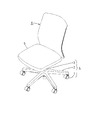
図1および図2に示すように、この椅子においては、先端にキャスタ1を設けた放射状に延びる5本の脚2の中央に支柱3を立設してなる脚体4における上記支柱3の上端に、座5および背凭れ6を支持する支持体7が設けられている。
Hereinafter, an embodiment of the present invention will be described with reference to the drawings.
As shown in FIGS. 1 and 2, in this chair, the upper end of the column 3 in a
背凭れ6は、支持体7より後方に向かって延出した後、起立する側面視前向L字状をなす背凭れ支持杆8(図3参照)における起立部の上部によって支持されている。
背凭れ支持杆8の前端部は、前端部が左右方向を向く軸(図示略)をもって、支持体7に枢着され、背凭れ6とともに、支持体7に対して後傾可能となっているが、その後傾のためのリクライニング機構に関しては、本発明に直接関係しないので、図示および詳細な説明は省略する。
なお、背凭れ支持杆8の前端部を、支持体7に固着して実施することもある。
The
The front end portion of the
In some cases, the front end portion of the
背凭れ6は、硬質合成樹脂材料よりなる正面視ほぼ方形枠状の背凭れフレーム9と、その前面に装着されたエラストマーまたは軟質合成樹脂材料等の可撓性を有する軟質材料よりなる背当部材10と、この背当部材10の前面と外周部とを被包するようにして背当部材10に装着された袋状の表皮材11と、硬質合成樹脂材料よりなり、背凭れフレーム9の後面を覆うようにして、背凭れフレーム9に装着された後面カバー12とを備えている。
The
背凭れフレーム9は、側面視において上下方向の中央部よりやや下方の部分が、前方に向かって突出するように緩やかに屈曲する、上下方向を向く左右1対の縦杆13、13と、その上端部同士を連結するとともに、平面視において左右方向の中央部が後方に突出するようにほぼ円弧状に湾曲する上部連結部14と、左右の縦杆13、13の下端部同士を、上部連結部14の上下幅より大きい上下幅を持って連結するとともに、平面視において左右方向の中央部が後方に突出するようにほぼ円弧状に湾曲する下部連結部15と、この下部連結部15の上端における左右方向の中央部から、左右の縦杆13、13のやや上部に向かって互いに拡開するように斜めに延出する左右1対の傾斜杆16、16とを備えている。なお、背凭れフレーム9と背凭れ支持杆8とを、一体成形されたひとつの部材とすることもある。
The
図6および図7に示すように、下部連結部15における左右方向の中央部には、下端のみが開口する方形の凹部17が設けられ、この凹部17に、背凭れ支持杆8の後部の起立部の上端部が下方より嵌合され、その上端部と下部連結部15における凹部17の前壁18とを、4個のボルト・ナット19をもって締着することにより、背凭れフレーム9は、背凭れ支持杆8の後部の起立部の上端部に安定よく固着されている。
背凭れ支持杆8の起立部は、図3に示すように、左右方向を向く金属板の左右両側部に、前方に向かって突出する平面視コ字状に突出する上下方向を向く突条8a、8aを折曲形成してなり、図7に示すように、各突条8aの上部2箇所において、ボルト・ナット19をもって前壁18に締着されている。
As shown in FIG. 6 and FIG. 7, a rectangular
As shown in FIG. 3, the upright portion of the
図3、および図8〜図13に示すように、背凭れフレーム9における左右の各縦杆13の前面には、上下方向を向く前向凹溝20が設けられ、この凹溝20と交差するように、各縦杆13には、左右方向を向く複数のピン挿入孔21が、上下方向に適宜の間隔をもって設けられている。
As shown in FIG. 3 and FIG. 8 to FIG. 13, a front
図4、図5、および図10に示すように、各縦杆13の後面における外側部には、各ピン挿入孔21にピンを案内するための左右方向を向く円弧状の案内溝22が設けられている。
また、図4、図5、および図8に示すように、各縦杆13における凹溝20の底部であって、ピン挿入孔21に対応する部分には、前後方向に貫通する縦長の貫通孔23が設けられている。
As shown in FIGS. 4, 5, and 10, an
As shown in FIGS. 4, 5, and 8, the bottom portion of the
図4、図5、および図12に示すように、各縦杆13の下部であって、下部連結部15の両側部には、凹溝20の一部を含んで前後方向に貫通する方形の貫通孔24が設けられている。
As shown in FIGS. 4, 5, and 12, a rectangular shape penetrating in the front-rear direction including a part of the
図4、図5、図11、および図13に示すように、各縦杆13の後面における上記貫通孔24を挾む上下部には、段付き孔25、25が設けられている。
As shown in FIGS. 4, 5, 11, and 13, stepped
図3、図5、および図8に示すように、各縦杆13の上端であって、上部連結部14の両側部には、平面視ほぼ方形の係合孔26が設けられている。
As shown in FIGS. 3, 5, and 8, engagement holes 26 having a substantially square shape in a plan view are provided at both ends of the upper connecting
図3〜図5、および図9に示すように、上部連結部14の後面における左右方向の中央部には、左右方向を向く長円形の浅い凹入段部27が設けられており、その凹入段部27の中央には、ねじ挿通孔28が、またその両側部には、オプション部材取付孔29、29が設けられている。
As shown in FIG. 3 to FIG. 5 and FIG. 9, an oval shallow recessed
上部連結部14の後面における凹入段部27の両側方には、位置決め孔30、30が、さらにその外側の両側方には、段付き孔31、31が設けられている。
Positioning holes 30 and 30 are provided on both sides of the recessed
背凭れフレーム9の前面および後面には、補強および材料の軽減を目的とした多数のリブや肉抜き孔が設けられているが、それらについては、本発明に関連するもののみについて説明し、その他については説明を省略する。
The front and rear surfaces of the
図3、および図9〜図13に示すように、背凭れフレーム9には、各縦杆13の内側の縁を形成するとともに、そこから上下に延長して、上部連結部14および下部連結部15の前面におけるリブを形成する縦リブ32が設けられている。
背当部材10の両側部を支持する支持手段(後述する)よりも内方において、左右の縦杆13の前面、すなわち各縦リブ32の前面は、背当部材10の両側端部の後面から離間することにより、背当部材10の後方への弾性変形を許容する、上下方向に連続する変形許容部33とされ、背当部材10における支持手段よりも内方の両側端部が、左右の縦リブ32の変形許容部33と当接するまで、後方に弾性変形しうるようになっている。したがって、左右の縦リブ32の前後方向の寸法を大小異ならせて、変形許容部33における背当部材10の後面との離間寸法を変更することにより、背当部材10の後方への弾性変形量を調整することができる。
左右の変形許容部33の前面は、背当部材10の後面からの離間寸法が、内側方に向かって漸次増大するなだらかな円弧状の変形許容曲面33aとしてある。
As shown in FIG. 3 and FIGS. 9 to 13, the
Inside the support means (described later) for supporting both side portions of the
The front surfaces of the left and right
この変形許容曲面33aの曲率半径を、上部から下部に向かって漸次小とすることにより、変形許容部33と背当部材10との対向面の離間寸法を、上方に向かって漸次大となるようにしてある(図9〜図13参照)。
なお、図示は省略するが、変形許容曲面33aの曲率半径を、上部から下部に向かって漸次大とすることにより、変形許容部33と背当部材10との対向面の離間寸法を、下方に向かって漸次大とすることもある。また、変形許容曲面33aは、円弧状の曲面とする以外に、例えば内方に向かうにしたがって曲率半径が漸次小となる放物面、または一部にフラットな傾斜面を有するものとしてもよい。
また、このような変形許容曲面33aを設けないで、縦リブ32の前面全体を、背当部材10の両側部の後面と平行な平坦面をなす形状としてもよい。
By making the curvature radius of the deformation allowable
Although illustration is omitted, by increasing the radius of curvature of the deformation-permitting
Further, the entire front surface of the
各縦杆13は、上記縦リブ32と、縦杆13の外側面を形成する縦リブ34との間の前面に、上下方向を向く肉抜き凹溝35と上記凹溝20とが互いに並列して設けられた、ほぼ前向き凵状断面をなしている。
In each
図3〜図5に示すように、背当部材10は、正面視ほぼ方形をなし、上下左右の縁部を除く内側の部分には、多数の小孔36を設けることにより、その部分を撓み易くしたもので、左右両側部の後面には、上下方向を向く差込片37、37が、後方に向かって突出するようにして一体的に設けられている。
As shown in FIGS. 3 to 5, the
各差込片37には、背凭れフレーム9の各縦杆13における複数のピン挿入孔21と対応する部分に、左右方向を向くピン挿入孔38が、また各縦杆13における貫通孔24と対応する部分に、後端部に内向きの係合爪39aを有する弾性係合片39がそれぞれ設けられている。
各差込片37の後端縁における各ピン挿入孔38の後方の部分には、各ピン挿入孔38の中心を曲率中心とする側面視円弧状の突部37aが形成されている。
Each
A
背当部材10の上半部の後面における左右の差込片37、37の外側の部分には、各差込片37と平行の左右1対の縦リブ40、40が設けられている。各縦リブ40における上部の3個のピン挿入孔38に対応する部分には、ピンの挿入の妨げとならないための円弧状の切欠き40aが設けられている。
A pair of left and right
図6〜図8に示すように、背当部材10の上部には、後上方に向かって緩く屈曲する屈曲部10aが形成されており、この屈曲部10aの後面における上端より下方の部分には、平面視および後面視において三日月形をなし、かつ左右方向の中央部の縦断面形状が前方に凸の円弧状をなし、かつ屈曲部10aの後面に対して鋭角をなして後下方を向く下向片41と、その下縁から鈍角をなして後方に向かって延出する後向片42と、下向片41と後向片42との結合部から垂下する垂下片43とが、一体的に設けられている。
この下向片41と後向片42とにより、背凭れ支持部材である背凭れフレーム9の上端から上方に離間するようにして、背当部材10の上部後面から後方に向かって延出し、かつ背当部材10と背凭れフレーム9との間の空間の上方と、背凭れフレーム9の上方とを覆う後覆い部が形成されている。
後向片42は、下向片41の左右方向の外側においても延出し、その外側の部分の後端は、屈曲部10aの後面と一体となっている。
As shown in FIGS. 6 to 8, a
The
The
垂下片43から両側方に離間する後向片42の両側部後端には、下端に前向き片44aを有し、かつ背当部材10の各側部を背凭れフレーム9に係止させる係止手段をなす下向きの係合片44が設けられている(図8参照)。
この係合片44の横断面形状は、図14に示すように、内側方に向かって拡開する楔状をなしている。
At the rear end of both sides of the
As shown in FIG. 14, the cross-sectional shape of the
垂下片43における左右方向の中央部とその両側方とには、背凭れフレーム9の上部連結部14におけるねじ挿通孔28とその両側方におけるオプション部材取付孔29、29、位置決め孔30、30、および段付き孔31、31に対応するボス挿通孔45、46、46、47、47、48、48が設けられている。
In the central part of the hanging
垂下片43の前面には、硬質合成樹脂材料よりなる補強材を兼ねる当て板49が配設されている。この当て板49の後面には、上記垂下片43におけるボス挿通孔45、46、46、47、47、48、48に対応し、それらに前方から嵌合しうる後方を向く複数のボス50、51、51、52、52、53、53が一体的に設けられている。
On the front surface of the hanging
図8〜図13に示すように、左右の各差込片37を、背凭れフレーム9の前面における左右の凹溝20に前方より挿入し、対応するピン挿入孔21とピン挿入孔38とを整合させた状態で、ピン54を背凭れフレーム9の両側方から、各ピン挿入孔21とピン挿入孔38とに挿入して(図10参照)、差込片37を凹溝20から抜け止めし、かつ弾性係合片39を貫通孔24に嵌合して、その後端の係合爪39aを、貫通孔24の後端の外側の縁に係止させ(図12参照)、さらに、垂下片43の前面に配設した当て板49のボス50、51、51、52、52、53、53を、垂下片43におけるボス挿通孔45、46、46、47、47、48、48に嵌合し、かつボス52、52、53、53を、背凭れフレーム9の上部連結部14における位置決め孔30、30および段付き孔31、31に嵌合し、かつ各段付き孔31に後方より挿通させた止めねじ55を、ボス53に設けた雌ねじ孔56に螺合して締め付けることにより(図9参照)、背当部材10は、背凭れフレーム9に、強固に、かつ安定よく装着されている。
なお、上記差込片37、ピン54、弾性係合片39、および突片24a等により、背凭れフレーム9の左右の縦杆13に、背当部材10の両側部を支持する支持手段を構成している。
As shown in FIGS. 8 to 13, the left and
The
各差込片37を、背凭れフレーム9の前面における左右の凹溝20に前方より挿入したとき、差込片37の後端における円弧状の各突部37aが、背凭れフレーム9における対応する貫通孔23に嵌合することにより、各差込片37は、背凭れフレーム9に対して上下方向に位置決めされる。
When each
図3および図4に示すように、背凭れフレーム9の両側方よりピン挿入孔21に挿入する上方の3本のピン54の頭部同士は、上下方向を向く連結杆57をもって互いに連結され、各ピン54をピン挿入孔21に挿入したとき、図10に示すように、連結杆57が背凭れフレーム9の外側面に当接するようにしてある。
As shown in FIGS. 3 and 4, the heads of the upper three
図示は省略してあるが、背凭れフレーム9の両側の下方のピン挿入孔21に挿入する2本のピンも、連結杆57と同様の連結杆をもって連結し、上方の3個のピン54と同様にして、背凭れフレーム9の下方のピン挿入孔21に挿入するのがよい。
なお、弾性係合片39の係合爪39aを、貫通孔24の後端の外側の縁に係止させるだけでも、背当部材10の下部は背凭れフレーム9に確実に装着されるので、下方の2個のピンのピン挿入孔21への挿入は省略することもある。
Although not shown, the two pins to be inserted into the lower pin insertion holes 21 on both sides of the
Note that the lower portion of the
図5および図12に示すように、弾性係合片39の係合爪39aには、上下方向を向く係合孔39bを設けておき、係合爪39aを貫通孔24の後端の外側の縁に係止させたとき、上記係合孔39bに、背凭れフレーム9における貫通孔24の後端の外側の縁に突設した後方を向く突片24aが係合して、係合爪39aが、貫通孔24の後端の外側の縁から内方に外れるのを防止しうるようにしておくのが望ましい。
As shown in FIGS. 5 and 12, the
図3〜図5、および図8に示すように、背凭れフレーム9の上端両側部における係合孔26に、背当部材10の後面側の上隅部に設けた下向の係合片44を上方より嵌合して、係合孔26の前縁に係合させ、かつ係合片44の下端の前向き片44aが、係合孔26の下端の前縁に係合しうるようにしておくことにより、背当部材10の上端における左右の角部が、背凭れフレーム9から前方に剥離するのを防止することができる。
As shown in FIGS. 3 to 5 and FIG. 8, downward engaging
また、図6および図7に示すように、背当部材10を背凭れフレーム9の正規の位置に装着したとき、背当部材10における後向片42が、背凭れフレーム9の上端を覆うようにすることによって、外観の向上を図っている。
Further, as shown in FIGS. 6 and 7, when the
表皮材11は、織布、メッシュ地、その他の張材の外周縁部に形成した筒状の紐通し部11aに引き紐58(図6以降参照)を挿通し、背当部材10の前面と外周部とを被包させた後、背当部材10の後面側において、引き紐58を引き締めて結ぶことにより、背当部材10に装着されている。引き紐58は、伸縮性を有するものを使用することもある。
The
背当部材10に表皮材11を装着した状態で、背当部材10を上記のようにして背凭れフレーム9に装着することにより、背当部材10の両側部の後面側においては、表皮材11の両側部の端末における紐通し部11aが、背当部材10の後面側の縦リブ40の内側に係合した状態で、表皮材11における紐通し部11aから背当部材10の外側縁に沿って前方に折り返されるまでの部分が、背凭れフレーム9における縦リブ40の前端と、後面カバー12の前面における両側端より僅かに内方寄りの部分に突設した前向き片59の前端とによって、背当部材10の後面に向かって前向きに押圧され、表皮材11の両側部が背凭れフレーム9から外側方に外れるのが確実に阻止されている。
By attaching the
表皮材11における背当部材10の上端部において後面側に折り返された部分の下縁は、背当部材10の後面における下向片41と後向片42との結合部分に当接したり(図6参照)、下向片41より上方の背当部材10の後面に密接したり(図7参照)、背当部材10の後面と後向片42との連結部に当接したり(図8参照)するようになっている。
The lower edge of the upper end portion of the
表皮材11の下縁は、図6〜図8に示すように、背当部材10の下端部において、単に上向きに折り返されているだけである。
As shown in FIGS. 6 to 8, the lower edge of the
図3および図4に示すように、後面カバー12は、その前面に、上記の左右の前向き片59、59の他に、上端より僅かに下方の部分に突設され、かつ左右の前向き片59、59の上端と結合するようにした、前方に向かってほぼ水平に延出する前向き片60を備えている。
この前向き片60の左右両側部の前縁には、垂下片61、61が設けられている。
この垂下片61の前面は、図14に示すように、係合片44の後面と平行をなすように、平面視において外側部が内側部より前方に位置するように傾斜し、かつ横断面形状が、後方に向かって開口する後向コ字状をなしている。
As shown in FIGS. 3 and 4, the
Dripping
As shown in FIG. 14, the front surface of the drooping
後面カバー12の前面における下部の両側部には、背凭れフレーム9における貫通孔24に対応する正面視方形の嵌合突部62と、同じく上下の係合孔25、25に対応する円筒状の係合突部63、63とが突設されている。
各係合突部63の先端部には、外向きの係止爪63aが設けられている。
On both sides of the lower portion of the front surface of the
An outward locking
後面カバー12の後面における上部の左右方向の中央部には、左右方向を向く長円形の浅い凹入段部64が設けられており、その凹入段部64の中央には、ねじ挿通孔65が、またその両側部には、オプション部材取付孔66、66が設けられている。
An oval shallow recessed
図8および図14に示すように、背当部材10の係合片44が前縁に係合された、背凭れフレーム9の上端両側部の係合孔26に、左右の垂下片61を、その前面が係合片44の後面に当接か、または近接するようにして嵌合し、図12に示すように、背当部材10における弾性係合片39の係合爪39aが後端の外側の縁に係止された、背凭れフレーム9の左右の貫通孔24に、左右の嵌合突部62を、その外側面が弾性係合片39の内側面に当接するようにして嵌合し、図11および図13に示すように、各係合突部63を、背凭れフレーム9における対応する段付き孔25に嵌合して、その係止爪63aを段付き孔25の前端縁に係止し、さらに、図6および図9に示すように、後面カバー12の後方から、ねじ挿通孔65と、背凭れフレーム9のねじ挿通孔28とを順次挿通させた止めねじ67を、当て板49のボス50に設けた雌ねじ孔68に螺合して締め付けることにより、後面カバー12は、背凭れフレーム9の後面に、強固に、かつ安定よく装着されている。
As shown in FIGS. 8 and 14, left and right hanging
図10に示すように、後面カバー12を背凭れフレーム9に装着した状態において、ピン54と一体をなす連結杆57は、後面カバー12の左右両側部における前面、および/または左右の前向き片59と当接することにより押えられ、外側方への脱落が防止されている。これにより、ピン54のピン挿入孔38からの脱落を防止する脱落防止手段を別途設けることなく、ピン54の脱落が防止されるとともに、背当部材10の背凭れフレーム9からの脱落も防止される。なお、複数のピン54を連結杆57により連結しないで、ピン54を単体で使用することもできるが、この際には、各ピン54に拡径頭部を設け、この拡径頭部を、後面カバー12における両側部の前面により押えうるようにすれば、その脱落を防止することができる。
As shown in FIG. 10, in the state where the
また、左右の垂下片61を、背当部材10の係合片44が前縁に係合された、背凭れフレーム9の上端両側部の係合孔26に、上記のようにして嵌合することにより、係合片44を係合孔26から抜け止めすることができ、また、左右の嵌合突部62を、背当部材10における弾性係合片39の係合爪39aが後端の外側の縁に係止された、背凭れフレーム9の左右の貫通孔24に、上記のようにして嵌合することにより、弾性係合片39を貫通孔24から抜け止めすることができる。
Further, the left and right hanging
後面カバー12の後面における凹入段部64には、銘板を兼ねるキャップ69が、着脱可能として嵌着されている。
A
以上説明したように、上記実施形態の椅子においては、背当部材10の両側部を支持する支持手段よりも内方の左右の縦リブ32を、その前面が背当部材10の両側端部の後面から離間するとともに、上下方向に連続する変形許容部33としたことにより、着座者の背中により背当部材10が後方へ押圧された際に、その中央部が後方に弾性変形するのに伴なって、背当部材10の左右両側部も、差込片37を支点として、その部分の後面が左右の縦リブ32の前面の変形許容曲面33aと当接するまで、後方に容易に弾性変形する。従って、背当部材10の中央部と両側部との変形量に大きな差が生じにくくなり、背当部材10全体が効果的に後方に弾性変形することにより、着座者の背中全体が快適に支持されるようになる。
As described above, in the chair of the above-described embodiment, the left and right
また、変形許容部33の前面を、背当部材10の後面からの離間寸法が内側方に向かって漸次増大するなだらかな変形許容曲面33aとしてあるので、背当部材10が変形許容曲面33aに当接するまで後方に弾性変形した後、さらにその変形許容曲面33aに沿うようにして、背当部材10の両側部が後方に弾性変形し易くなるので、背当部材10の両側部の変形量が大となり、着座者の背中がより快適に支持されるとともに、背当部材10の両側部に大きな曲げ応力が加わらないので、縦杆13と当接する後面が損耗する恐れが小さくなる。
Further, since the front surface of the
さらに、背当部材10の後面と変形許容部33との対向面の離間寸法を、上方に向かって漸次大となるようにしてあるので、背中の荷重が大きく加わる背当部材10の上部の両側部ほど、後方に大きく弾性変形し、背凭れ6をリクライニングさせて背中を凭れ掛けた際の感触がよくなる。
なお、背当部材10の後面と変形許容部33との対向面の離間寸法を、下方に向かって漸次大となるようにした際には、臀部を座5の奥部に位置させて深く着座し、この状態で背凭れ6をリクライニングさせたときにおいて、背当部材10の下部の両側部ほど、後方に大きく弾性変形するので、腰部付近が快適に支持される。
Furthermore, since the distance between the rear surface of the
In addition, when the separation dimension of the opposing surface of the back surface of the
本発明は、上記実施形態のみに限定されるものではなく、例えば、次のような幾多の変形した態様での実施が可能である。
(1) 縦杆13を、左右の縦リブ32、34や凹溝20のない中実状とし、その内側方の前面に、変形許容部33を設けることもある。この際には、背当部材10の差込片37を、例えば縦杆13の外側面に、ねじやピン等により固定すればよい。
(2) 背当部材10を、例えばポリプロピレンやポリアミド等の硬質材料により板状に成形し、これに多数の小孔を設けたものとする。このようにすると、背当部材10の可撓性は、軟質材料により成形したものよりも小となるが、変形許容曲面33aの曲率半径を大としたり、背当部材10の両側部の厚さを部分的に小としたりすれば、背当部材10の両側部の可撓性が阻害されることはない。
(3) 背当部材10を、左右の縦杆13、13同士の上下方向の全領域を、板状の連結部材により連結し、左右の縦杆13、13間の空間が閉塞された板状をなす背凭れフレームとする。この際には、左右の縦杆13を除いた板状をなす部分の前面を、縦杆13の前面よりも後方に位置させて、板状をなす部分と背当部材10との対向面間に、背当部材10を後方に弾性変形させるための空間を設ければよい。このように、背凭れフレームを板状とした際には、後面カバー12を省略することができる。
(4) 背当部材10、または後面カバー12の一方を軟質材料により形成するとともに、被嵌合部である係合孔26の前後方向の幅を、嵌合部である係合片44の前後方向の厚さと垂下片61の前後方向の厚さとの和より僅かに小とする。
このようにすると、係合片44、または垂下片61の一方が、係合孔26への嵌合状態において、他方を強く押し付けるようになるので、軟質材料で形成された側の部材の脱落を確実に防止できる。
(5) 背当部材10、および後面部材12の両方を硬質材料により形成する。
(6) 係合片44に設けた前向き片44aを省略し、嵌合部である係合片44を、側面視下向き鉤形とする。
そうすることによって、背当部材10を、後面カバー12に妨げられることなく、単独で背凭れフレーム9から取り外すことができる。
(7) 背凭れフレーム9の上端に設ける被嵌合部を、縦杆13の上端面よりも若干下方に、前後方向に貫通するように設けられた係合孔とする。
(8) 後面カバー12から前向き片60を省略し、垂下片61を後面カバー12の前面から突設する。
(9) 各垂下片61の左右方向の幅を、背当部材10の係合片44の左右方向の幅とほぼ同一で、かつ被嵌合部である係合孔26の左右方向の幅とほぼ同一か、または僅かに小とする。
The present invention is not limited to the above-described embodiment, and can be implemented in various modified modes as follows, for example.
(1) The
(2) The
(3) A plate-like member in which the
(4) One of the
In this case, one of the
(5) Both the
(6) The
By doing so, the
(7) The fitting portion provided at the upper end of the
(8) The
(9) The width of each hanging
1 キャスタ
2 脚
3 支柱
4 脚体
5 座
6 背凭れ
7 支持体
8 背凭れ支持杆
8a突条
9 背凭れフレーム
10 背当部材
10a屈曲部
11 表皮材
11a紐通し部
12 後面カバー
13 縦杆
14 上部連結部
15 下部連結部
16 傾斜杆
17 凹部
18 前壁
19 ボルト・ナット
20 凹溝
21 ピン挿入孔
22 案内溝
23 貫通孔
24 貫通孔
24a突片
25 段付き孔
26 係合孔
27 凹入段部
28 ねじ挿通孔
29 オプション部材取付孔
30 位置決め孔
31 段付き孔
32 縦リブ
33 変形許容部
33a変形許容曲面
34 縦リブ
35 肉抜き凹溝
36 小孔
37 差込片
37a突部
38 ピン挿入孔
39 弾性係合片
39a係合爪
39b係合孔
40 縦リブ
40a切欠き
41 下向片
42 後向片
43 垂下片
44 係合片
44a前向き片
45、46、46、47、48 ボス挿通孔
49 当て板
50、51、52、53 ボス
54 ピン
55 止めねじ
56 雌ねじ孔
57 連結杆
58 引き紐
59、60 前向き片
61 垂下片
62 嵌合突部
63 係合突部
63a係止爪
64 凹入段部
65 ねじ挿通孔
66 オプション部材取付孔
67 止めねじ
68 雌ねじ孔
69 キャップ
DESCRIPTION OF SYMBOLS 1
Claims (5)
前記背当部材は、エラストマーまたは軟質合成樹脂材料等の板状軟質材料により形成され、
前記支持手段よりも内方において前記左右の縦杆に形成された縦リブの前面を、前記背当部材の両側端部の後面から離間させることにより、背当部材の後方への弾性変形を許容する変形許容部とし、かつ前記変形許容部の前面を、背当部材の後面からの離間寸法が内側方に向かって漸次曲面状に増大する変形許容曲面としたことを特徴とする椅子。 In a chair comprising a backrest frame having a pair of vertical saddles spaced apart from each other on the left and right, and a flexible backrest member whose left and right sides are supported by support means on the front side of the left and right vertical saddles,
The backrest member is formed of a plate-like soft material such as an elastomer or a soft synthetic resin material,
By allowing the front surfaces of the vertical ribs formed on the left and right vertical saddles to be inward of the support means, the elastic deformation of the back support member to the rear is allowed by separating the front surfaces of the back support members from the rear surfaces of both end portions. And a front surface of the deformation-permitting portion is a deformation-permitted curved surface in which a distance from the rear surface of the backrest member gradually increases in a curved shape toward the inside .
Priority Applications (1)
| Application Number | Priority Date | Filing Date | Title |
|---|---|---|---|
| JP2012147314A JP6092532B2 (en) | 2012-06-29 | 2012-06-29 | Chair |
Applications Claiming Priority (1)
| Application Number | Priority Date | Filing Date | Title |
|---|---|---|---|
| JP2012147314A JP6092532B2 (en) | 2012-06-29 | 2012-06-29 | Chair |
Publications (2)
| Publication Number | Publication Date |
|---|---|
| JP2014008254A JP2014008254A (en) | 2014-01-20 |
| JP6092532B2 true JP6092532B2 (en) | 2017-03-08 |
Family
ID=50105465
Family Applications (1)
| Application Number | Title | Priority Date | Filing Date |
|---|---|---|---|
| JP2012147314A Expired - Fee Related JP6092532B2 (en) | 2012-06-29 | 2012-06-29 | Chair |
Country Status (1)
| Country | Link |
|---|---|
| JP (1) | JP6092532B2 (en) |
Families Citing this family (2)
| Publication number | Priority date | Publication date | Assignee | Title |
|---|---|---|---|---|
| JP6529152B2 (en) * | 2014-05-15 | 2019-06-12 | 株式会社オカムラ | Backrests for chairs and chairs |
| JP7198018B2 (en) * | 2017-10-11 | 2022-12-28 | 日東電工株式会社 | Battery packs, wireless power transfer systems and hearing aids |
Family Cites Families (3)
| Publication number | Priority date | Publication date | Assignee | Title |
|---|---|---|---|---|
| US5662383A (en) * | 1995-08-11 | 1997-09-02 | Bemis Manufacturing Company | Apparatus for attaching fabric to a chair frame |
| JP5260027B2 (en) * | 2007-10-29 | 2013-08-14 | 株式会社イトーキ | Chair |
| JP5513187B2 (en) * | 2010-03-18 | 2014-06-04 | 株式会社岡村製作所 | Extension structure of chair upholstery |
-
2012
- 2012-06-29 JP JP2012147314A patent/JP6092532B2/en not_active Expired - Fee Related
Also Published As
| Publication number | Publication date |
|---|---|
| JP2014008254A (en) | 2014-01-20 |
Similar Documents
| Publication | Publication Date | Title |
|---|---|---|
| US7178864B2 (en) | Foldable chair having a detachable fabric sheet | |
| EP2215931A1 (en) | Backrest of chair and its fixing device | |
| JP5693837B2 (en) | Chair | |
| JP5567821B2 (en) | Chair back | |
| JP2006280454A (en) | Chair with hanger | |
| JP5902570B2 (en) | Chair | |
| JP6092532B2 (en) | Chair | |
| JP6162376B2 (en) | Chair | |
| JP4904519B2 (en) | Chair | |
| JP5940916B2 (en) | Chair | |
| JP5940915B2 (en) | Chair | |
| JP2009172125A (en) | Fixing device of backrest of chair | |
| JP5513152B2 (en) | Extension structure of chair upholstery | |
| WO2016084766A1 (en) | Seat | |
| KR200423241Y1 (en) | Hinge structure of chair | |
| JP4800754B2 (en) | Chair | |
| JP5989755B2 (en) | Chair back | |
| JP6001895B2 (en) | Chair backrest mounting structure | |
| JP6092539B2 (en) | Method of attaching skin material to chair substrate and chair | |
| JP5926033B2 (en) | Chair | |
| JP2015083202A5 (en) | ||
| JP5981148B2 (en) | Mounting structure for optional members on chair back | |
| JP5873304B2 (en) | Chair with armrests | |
| JP2012135488A (en) | Chair with backrest | |
| JP6608248B2 (en) | Chair |
Legal Events
| Date | Code | Title | Description |
|---|---|---|---|
| A621 | Written request for application examination |
Free format text: JAPANESE INTERMEDIATE CODE: A621 Effective date: 20150608 |
|
| A977 | Report on retrieval |
Free format text: JAPANESE INTERMEDIATE CODE: A971007 Effective date: 20160427 |
|
| A131 | Notification of reasons for refusal |
Free format text: JAPANESE INTERMEDIATE CODE: A131 Effective date: 20160517 |
|
| A521 | Written amendment |
Free format text: JAPANESE INTERMEDIATE CODE: A523 Effective date: 20160714 |
|
| TRDD | Decision of grant or rejection written | ||
| A01 | Written decision to grant a patent or to grant a registration (utility model) |
Free format text: JAPANESE INTERMEDIATE CODE: A01 Effective date: 20170110 |
|
| A61 | First payment of annual fees (during grant procedure) |
Free format text: JAPANESE INTERMEDIATE CODE: A61 Effective date: 20170209 |
|
| R150 | Certificate of patent or registration of utility model |
Ref document number: 6092532 Country of ref document: JP Free format text: JAPANESE INTERMEDIATE CODE: R150 |
|
| S533 | Written request for registration of change of name |
Free format text: JAPANESE INTERMEDIATE CODE: R313533 |
|
| R350 | Written notification of registration of transfer |
Free format text: JAPANESE INTERMEDIATE CODE: R350 |
|
| LAPS | Cancellation because of no payment of annual fees |