JP6091815B2 - Secondary battery - Google Patents
Secondary battery Download PDFInfo
- Publication number
- JP6091815B2 JP6091815B2 JP2012196922A JP2012196922A JP6091815B2 JP 6091815 B2 JP6091815 B2 JP 6091815B2 JP 2012196922 A JP2012196922 A JP 2012196922A JP 2012196922 A JP2012196922 A JP 2012196922A JP 6091815 B2 JP6091815 B2 JP 6091815B2
- Authority
- JP
- Japan
- Prior art keywords
- short
- current collector
- secondary battery
- circuit member
- electrode
- Prior art date
- Legal status (The legal status is an assumption and is not a legal conclusion. Google has not performed a legal analysis and makes no representation as to the accuracy of the status listed.)
- Active
Links
- 238000007789 sealing Methods 0.000 claims description 2
- 230000006698 induction Effects 0.000 description 12
- PXHVJJICTQNCMI-UHFFFAOYSA-N Nickel Chemical compound [Ni] PXHVJJICTQNCMI-UHFFFAOYSA-N 0.000 description 4
- 239000007772 electrode material Substances 0.000 description 4
- 239000000463 material Substances 0.000 description 4
- -1 polyethylene Polymers 0.000 description 4
- 229910052782 aluminium Inorganic materials 0.000 description 3
- XAGFODPZIPBFFR-UHFFFAOYSA-N aluminium Chemical compound [Al] XAGFODPZIPBFFR-UHFFFAOYSA-N 0.000 description 3
- 239000003792 electrolyte Substances 0.000 description 3
- 229910052751 metal Inorganic materials 0.000 description 3
- 239000002184 metal Substances 0.000 description 3
- 229910000838 Al alloy Inorganic materials 0.000 description 2
- OKTJSMMVPCPJKN-UHFFFAOYSA-N Carbon Chemical compound [C] OKTJSMMVPCPJKN-UHFFFAOYSA-N 0.000 description 2
- RYGMFSIKBFXOCR-UHFFFAOYSA-N Copper Chemical compound [Cu] RYGMFSIKBFXOCR-UHFFFAOYSA-N 0.000 description 2
- 239000004698 Polyethylene Substances 0.000 description 2
- 239000004743 Polypropylene Substances 0.000 description 2
- 239000004020 conductor Substances 0.000 description 2
- 229910052802 copper Inorganic materials 0.000 description 2
- 239000010949 copper Substances 0.000 description 2
- 239000011888 foil Substances 0.000 description 2
- 230000001939 inductive effect Effects 0.000 description 2
- 229920000573 polyethylene Polymers 0.000 description 2
- 229920001155 polypropylene Polymers 0.000 description 2
- 229910000881 Cu alloy Inorganic materials 0.000 description 1
- 229910000570 Cupronickel Inorganic materials 0.000 description 1
- HBBGRARXTFLTSG-UHFFFAOYSA-N Lithium ion Chemical compound [Li+] HBBGRARXTFLTSG-UHFFFAOYSA-N 0.000 description 1
- 229910000990 Ni alloy Inorganic materials 0.000 description 1
- 229910000831 Steel Inorganic materials 0.000 description 1
- 230000000712 assembly Effects 0.000 description 1
- 238000000429 assembly Methods 0.000 description 1
- 230000000903 blocking effect Effects 0.000 description 1
- 229910052799 carbon Inorganic materials 0.000 description 1
- 239000002131 composite material Substances 0.000 description 1
- 238000005868 electrolysis reaction Methods 0.000 description 1
- 238000004880 explosion Methods 0.000 description 1
- 229910002804 graphite Inorganic materials 0.000 description 1
- 239000010439 graphite Substances 0.000 description 1
- 239000011810 insulating material Substances 0.000 description 1
- 239000012212 insulator Substances 0.000 description 1
- 239000007788 liquid Substances 0.000 description 1
- 229910001416 lithium ion Inorganic materials 0.000 description 1
- 239000000155 melt Substances 0.000 description 1
- 239000012528 membrane Substances 0.000 description 1
- 230000004048 modification Effects 0.000 description 1
- 238000012986 modification Methods 0.000 description 1
- 229910052759 nickel Inorganic materials 0.000 description 1
- 230000002093 peripheral effect Effects 0.000 description 1
- 239000010959 steel Substances 0.000 description 1
- 230000007704 transition Effects 0.000 description 1
- 229910000314 transition metal oxide Inorganic materials 0.000 description 1
- 238000004804 winding Methods 0.000 description 1
Images


Classifications
-
- H—ELECTRICITY
- H01—ELECTRIC ELEMENTS
- H01M—PROCESSES OR MEANS, e.g. BATTERIES, FOR THE DIRECT CONVERSION OF CHEMICAL ENERGY INTO ELECTRICAL ENERGY
- H01M50/00—Constructional details or processes of manufacture of the non-active parts of electrochemical cells other than fuel cells, e.g. hybrid cells
- H01M50/50—Current conducting connections for cells or batteries
- H01M50/572—Means for preventing undesired use or discharge
- H01M50/574—Devices or arrangements for the interruption of current
- H01M50/578—Devices or arrangements for the interruption of current in response to pressure
-
- H—ELECTRICITY
- H01—ELECTRIC ELEMENTS
- H01M—PROCESSES OR MEANS, e.g. BATTERIES, FOR THE DIRECT CONVERSION OF CHEMICAL ENERGY INTO ELECTRICAL ENERGY
- H01M10/00—Secondary cells; Manufacture thereof
- H01M10/42—Methods or arrangements for servicing or maintenance of secondary cells or secondary half-cells
-
- H—ELECTRICITY
- H01—ELECTRIC ELEMENTS
- H01M—PROCESSES OR MEANS, e.g. BATTERIES, FOR THE DIRECT CONVERSION OF CHEMICAL ENERGY INTO ELECTRICAL ENERGY
- H01M10/00—Secondary cells; Manufacture thereof
- H01M10/04—Construction or manufacture in general
- H01M10/0431—Cells with wound or folded electrodes
-
- H—ELECTRICITY
- H01—ELECTRIC ELEMENTS
- H01M—PROCESSES OR MEANS, e.g. BATTERIES, FOR THE DIRECT CONVERSION OF CHEMICAL ENERGY INTO ELECTRICAL ENERGY
- H01M10/00—Secondary cells; Manufacture thereof
- H01M10/42—Methods or arrangements for servicing or maintenance of secondary cells or secondary half-cells
- H01M10/44—Methods for charging or discharging
- H01M10/445—Methods for charging or discharging in response to gas pressure
-
- H—ELECTRICITY
- H01—ELECTRIC ELEMENTS
- H01M—PROCESSES OR MEANS, e.g. BATTERIES, FOR THE DIRECT CONVERSION OF CHEMICAL ENERGY INTO ELECTRICAL ENERGY
- H01M50/00—Constructional details or processes of manufacture of the non-active parts of electrochemical cells other than fuel cells, e.g. hybrid cells
- H01M50/10—Primary casings, jackets or wrappings of a single cell or a single battery
- H01M50/147—Lids or covers
- H01M50/166—Lids or covers characterised by the methods of assembling casings with lids
- H01M50/169—Lids or covers characterised by the methods of assembling casings with lids by welding, brazing or soldering
-
- H—ELECTRICITY
- H01—ELECTRIC ELEMENTS
- H01M—PROCESSES OR MEANS, e.g. BATTERIES, FOR THE DIRECT CONVERSION OF CHEMICAL ENERGY INTO ELECTRICAL ENERGY
- H01M50/00—Constructional details or processes of manufacture of the non-active parts of electrochemical cells other than fuel cells, e.g. hybrid cells
- H01M50/30—Arrangements for facilitating escape of gases
-
- H—ELECTRICITY
- H01—ELECTRIC ELEMENTS
- H01M—PROCESSES OR MEANS, e.g. BATTERIES, FOR THE DIRECT CONVERSION OF CHEMICAL ENERGY INTO ELECTRICAL ENERGY
- H01M50/00—Constructional details or processes of manufacture of the non-active parts of electrochemical cells other than fuel cells, e.g. hybrid cells
- H01M50/50—Current conducting connections for cells or batteries
- H01M50/531—Electrode connections inside a battery casing
- H01M50/533—Electrode connections inside a battery casing characterised by the shape of the leads or tabs
-
- H—ELECTRICITY
- H01—ELECTRIC ELEMENTS
- H01M—PROCESSES OR MEANS, e.g. BATTERIES, FOR THE DIRECT CONVERSION OF CHEMICAL ENERGY INTO ELECTRICAL ENERGY
- H01M50/00—Constructional details or processes of manufacture of the non-active parts of electrochemical cells other than fuel cells, e.g. hybrid cells
- H01M50/50—Current conducting connections for cells or batteries
- H01M50/531—Electrode connections inside a battery casing
- H01M50/538—Connection of several leads or tabs of wound or folded electrode stacks
-
- H—ELECTRICITY
- H01—ELECTRIC ELEMENTS
- H01M—PROCESSES OR MEANS, e.g. BATTERIES, FOR THE DIRECT CONVERSION OF CHEMICAL ENERGY INTO ELECTRICAL ENERGY
- H01M50/00—Constructional details or processes of manufacture of the non-active parts of electrochemical cells other than fuel cells, e.g. hybrid cells
- H01M50/50—Current conducting connections for cells or batteries
- H01M50/543—Terminals
-
- H—ELECTRICITY
- H01—ELECTRIC ELEMENTS
- H01M—PROCESSES OR MEANS, e.g. BATTERIES, FOR THE DIRECT CONVERSION OF CHEMICAL ENERGY INTO ELECTRICAL ENERGY
- H01M50/00—Constructional details or processes of manufacture of the non-active parts of electrochemical cells other than fuel cells, e.g. hybrid cells
- H01M50/50—Current conducting connections for cells or batteries
- H01M50/572—Means for preventing undesired use or discharge
- H01M50/574—Devices or arrangements for the interruption of current
- H01M50/583—Devices or arrangements for the interruption of current in response to current, e.g. fuses
-
- H—ELECTRICITY
- H01—ELECTRIC ELEMENTS
- H01M—PROCESSES OR MEANS, e.g. BATTERIES, FOR THE DIRECT CONVERSION OF CHEMICAL ENERGY INTO ELECTRICAL ENERGY
- H01M2200/00—Safety devices for primary or secondary batteries
- H01M2200/10—Temperature sensitive devices
- H01M2200/103—Fuse
-
- H—ELECTRICITY
- H01—ELECTRIC ELEMENTS
- H01M—PROCESSES OR MEANS, e.g. BATTERIES, FOR THE DIRECT CONVERSION OF CHEMICAL ENERGY INTO ELECTRICAL ENERGY
- H01M2200/00—Safety devices for primary or secondary batteries
- H01M2200/20—Pressure-sensitive devices
-
- H—ELECTRICITY
- H01—ELECTRIC ELEMENTS
- H01M—PROCESSES OR MEANS, e.g. BATTERIES, FOR THE DIRECT CONVERSION OF CHEMICAL ENERGY INTO ELECTRICAL ENERGY
- H01M50/00—Constructional details or processes of manufacture of the non-active parts of electrochemical cells other than fuel cells, e.g. hybrid cells
- H01M50/50—Current conducting connections for cells or batteries
- H01M50/543—Terminals
- H01M50/547—Terminals characterised by the disposition of the terminals on the cells
- H01M50/55—Terminals characterised by the disposition of the terminals on the cells on the same side of the cell
-
- H—ELECTRICITY
- H01—ELECTRIC ELEMENTS
- H01M—PROCESSES OR MEANS, e.g. BATTERIES, FOR THE DIRECT CONVERSION OF CHEMICAL ENERGY INTO ELECTRICAL ENERGY
- H01M50/00—Constructional details or processes of manufacture of the non-active parts of electrochemical cells other than fuel cells, e.g. hybrid cells
- H01M50/50—Current conducting connections for cells or batteries
- H01M50/543—Terminals
- H01M50/552—Terminals characterised by their shape
- H01M50/553—Terminals adapted for prismatic, pouch or rectangular cells
-
- Y—GENERAL TAGGING OF NEW TECHNOLOGICAL DEVELOPMENTS; GENERAL TAGGING OF CROSS-SECTIONAL TECHNOLOGIES SPANNING OVER SEVERAL SECTIONS OF THE IPC; TECHNICAL SUBJECTS COVERED BY FORMER USPC CROSS-REFERENCE ART COLLECTIONS [XRACs] AND DIGESTS
- Y02—TECHNOLOGIES OR APPLICATIONS FOR MITIGATION OR ADAPTATION AGAINST CLIMATE CHANGE
- Y02E—REDUCTION OF GREENHOUSE GAS [GHG] EMISSIONS, RELATED TO ENERGY GENERATION, TRANSMISSION OR DISTRIBUTION
- Y02E60/00—Enabling technologies; Technologies with a potential or indirect contribution to GHG emissions mitigation
- Y02E60/10—Energy storage using batteries
-
- Y—GENERAL TAGGING OF NEW TECHNOLOGICAL DEVELOPMENTS; GENERAL TAGGING OF CROSS-SECTIONAL TECHNOLOGIES SPANNING OVER SEVERAL SECTIONS OF THE IPC; TECHNICAL SUBJECTS COVERED BY FORMER USPC CROSS-REFERENCE ART COLLECTIONS [XRACs] AND DIGESTS
- Y02—TECHNOLOGIES OR APPLICATIONS FOR MITIGATION OR ADAPTATION AGAINST CLIMATE CHANGE
- Y02P—CLIMATE CHANGE MITIGATION TECHNOLOGIES IN THE PRODUCTION OR PROCESSING OF GOODS
- Y02P70/00—Climate change mitigation technologies in the production process for final industrial or consumer products
- Y02P70/50—Manufacturing or production processes characterised by the final manufactured product
Description
本発明は2次電池に関する。 The present invention relates to a secondary battery.
2次電池は、充電が不可能な一次電池とは異なり、充電および放電が可能な電池であって、一つの電池セルがパック形態に包装された低容量電池である場合には、携帯電話機およびカムコーダーのような携帯が可能な小型電子機器に用いられ、一方、電池パックが数十個連結された電池パック単位の大容量電池である場合には、ハイブリッド自動車などのモータ駆動用電源として幅広く用いられている。 Unlike a primary battery that cannot be charged, a secondary battery is a battery that can be charged and discharged. When a single battery cell is a low-capacity battery packaged in a pack, Used for portable electronic devices such as camcorders, and on the other hand, when the battery pack is a large-capacity battery with several tens of battery packs connected, it is widely used as a motor drive power source for hybrid vehicles and the like. It has been.
2次電池は様々な形状で製造されているが、代表的な形状には円筒形、角形が挙げられ、正、負極板の間に絶縁体であるセパレータを介在して形成された電極組立体と電解液とをケースに内装設置し、ケースに電極端子が形成されたキャップ組立体を設置して構成される。 Secondary batteries are manufactured in a variety of shapes, but typical shapes include cylindrical and square, and electrode assemblies and electrolysis formed by interposing a separator as an insulator between positive and negative plates. The liquid is installed in a case, and a cap assembly in which electrode terminals are formed is installed in the case.
一方、2次電池は外部短絡によってヒューズ領域が溶けながらアーク(arc)を発生する。このように発生するアークはヒューズ領域だけでなく2次電池の他の領域に転移して発火や爆発などの問題を起こす可能性がある。したがって、外部短絡に対する安全性が向上した構造の2次電池が要求されている。 Meanwhile, the secondary battery generates an arc while the fuse region melts due to an external short circuit. The arc generated in this manner may be transferred not only to the fuse region but also to other regions of the secondary battery to cause problems such as ignition and explosion. Therefore, a secondary battery having a structure with improved safety against an external short circuit is required.
本発明は、過充電および外部短絡に対して安定性が向上した2次電池を提供する。 The present invention provides a secondary battery having improved stability against overcharge and external short circuit.
本発明の一実施例による2次電池は、第1電極板、第2電極板、および前記第1電極板と前記第2電極板との間に介在するセパレータを含む電極組立体;前記第1電極板と電気的に連結され、ヒューズ領域を有する第1集電体;前記電極組立体および前記第1集電体を収容するケース;前記ケースの開口を密封し、短絡ホールを有するキャッププレート;前記短絡ホールに設けられる第1短絡部材;前記キャッププレートの上面から離隔し、前記第1短絡部材と向かい合って前記第2電極板と電気的に連結される第2短絡部材;および前記ケース内部で前記第1短絡部材にガス移動を誘導する誘導部材を含む。 A secondary battery according to an embodiment of the present invention includes a first electrode plate, a second electrode plate, and an electrode assembly including a separator interposed between the first electrode plate and the second electrode plate; A first current collector electrically connected to the electrode plate and having a fuse region; a case for housing the electrode assembly and the first current collector; a cap plate for sealing an opening of the case and having a short-circuit hole; A first short-circuit member provided in the short-circuit hole; a second short-circuit member spaced apart from an upper surface of the cap plate and facing the first short-circuit member and electrically connected to the second electrode plate; and in the case An induction member for inducing gas movement is included in the first short-circuit member.
また、前記誘導部材は、一側部に第1開放部を有し、他側部に第2開放部を有するダクト(duct)形態からなることができる。 The guide member may have a duct shape having a first open part on one side and a second open part on the other side.
また、前記誘導部材の一側部は、前記第1開放部が前記ヒューズ領域と対向するように前記第1集電体と連結されることができる。 The one side portion of the guide member may be connected to the first current collector such that the first open portion faces the fuse region.
また、前記誘導部材の他側部は、前記第2開放部が前記第1短絡部材と対向し、前記第1短絡部材および前記キャッププレートの下面と離隔できる。 Further, the other side of the guide member can be separated from the first short-circuit member and the lower surface of the cap plate, with the second opening portion facing the first short-circuit member.
また、前記誘導部材の他側部は、前記第1短絡部材に向かって突出する形態からなることができる。 The other side of the guide member may be configured to protrude toward the first short-circuit member.
また、前記誘導部材の他側部は、前記第2開放部が前記第1短絡部材に向かうように突出して前記キャッププレートの下面と連結され、前記誘導部材の他側部の突出部分は、前記ケース内部と通じる少なくとも一つ以上の第3開放部を有することができる。 The other side portion of the guide member protrudes so that the second opening portion faces the first short-circuit member, and is connected to the lower surface of the cap plate. At least one or more third opening portions communicating with the inside of the case can be provided.
また、前記ヒューズ領域は、前記第1集電体の他の領域より断面積が小さく形成されることができる。 The fuse region may be formed to have a smaller cross-sectional area than other regions of the first current collector.
また、前記第1短絡部材は、予め設定された圧力より大きい圧力を受けると形態が反転して前記第2短絡部材と電気的に接触できるように形成されることができる。 In addition, the first short-circuit member may be formed such that when a pressure larger than a preset pressure is applied, the form is reversed and the first short-circuit member can be electrically contacted with the second short-circuit member.
本発明によれば、過充電および外部短絡に対して安定性が向上した2次電池を提供することができる。 ADVANTAGE OF THE INVENTION According to this invention, the secondary battery which improved stability with respect to an overcharge and an external short circuit can be provided.
本発明の属する技術分野において通常の知識を有する者が容易に実施できる程度に、本発明の好ましい実施例を図面を参照して詳細に説明する。 The preferred embodiments of the present invention will be described in detail with reference to the drawings to the extent that those skilled in the art can easily carry out the present invention.
図1は、本発明の一実施例による2次電池100を示す斜視図である。図2は、図1のI−I’線に沿って切り取った2次電池100を示す断面図である。
FIG. 1 is a perspective view illustrating a
図1および図2を参照すれば、本発明の一実施例による2次電池100は、電極組立体110、第1集電体120、第2集電体130、ケース140、キャップ組立体150、第1短絡部材160、第2短絡部材161および誘導部材170を含む。
1 and 2, a
前記電極組立体110は、薄い板型あるいは膜型からなる第1電極板111、セパレータ113、第2電極板112の積層体を巻き取るか重ねることにより形成される。ここで、第1電極板111は正極として作用でき、第2電極板112は陰極として作用することができる。
The
前記第1電極板111は、アルミニウムのような金属箔からなる第1電極集電体に遷移金属酸化物などの第1電極活物質を塗布することによって形成され、第1電極活物質が塗布されない領域である第1電極無地部111aを含む。前記第1電極無地部111aは第1電極板111と、第1電極板外部との間の電流が流れる通路となる。ただし、前記第1電極板111の材質を限定するものではない。
The
前記第2電極板112は、ニッケルまたは銅のような金属箔からなる第2電極集電体に黒鉛または炭素などの第2電極活物質を塗布することによって形成され、第2電極活物質が塗布されない領域である第2電極無地部112aを含む。前記第2電極無地部112aは第2電極板112と、第2電極板外部との間の電流が流れる通路となる。ただし、前記第2電極板112の材質を限定するものではない。
The
このような第1電極板111および第2電極板112は極性を異にして配置される。
The
前記セパレータ113は、第1電極板111と第2電極板112との間に位置して短絡を防止し、リチウムイオンの移動を可能にする役割を果たし、ポリエチレンやポリプロピレンやポリエチレンとポリプロピレンとの複合フイルムからなることができる。ただし、前記セパレータ113の材質を限定するものではない。
The
このような電極組立体110の両側端部には第1電極板111および第2電極板112にそれぞれ電気的に連結するための第1集電体120と第2集電体130とが結合する。
A first
前記第1集電体120は、アルミニウムおよびアルミニウム合金などの導電性材質からなり、電極組立体110の一側端部に突出した第1電極無地部111aと接触することによって、第1電極板111と電気的に連結される。前記第1集電体120は、第1連結部121、第1延長部123、第1端子ホール124および第1ヒューズホール125を含んで構成される。前記第1集電体120の具体的な構成については以下に詳しく説明する。
The first
前記第2集電体130は、銅、銅合金、ニッケルおよびニッケル合金などの導電性材質からなり、電極組立体110の他側端部に突出した第2電極無地部112aと接触することによって第2電極板112と電気的に連結される。前記第2集電体130は、第2連結部131、第2延長部133および第2端子ホール134を含んで構成される。前記第2集電体130の具体的な構成については以下に詳しく説明する。
The second
前記ケース140は、アルミニウム、アルミニウム合金またはニッケルメッキをされたスチールのような導電性金属からなり、電極組立体110、第1集電体120および第2集電体130が挿入安着できるケース開口部が形成されたほぼ六面体形状からなる。図2では、ケース140とキャップ組立体150とが結合された状態で示されているので、ケース開口部が示されなかったが、キャップ組立体150の周り部分が実質的に開放された部分である。一方、ケース140の内面は絶縁処理されて、電極組立体110、第1集電体120、第2集電体130およびキャップ組立体150と絶縁される。ここで、前記ケース140は一つの極性、例えば正極として作用することができる。
The
前記キャップ組立体150は前記ケース140に結合される。前記キャップ組立体150は、具体的には、キャッププレート151、第1電極端子152、第2電極端子153、ガスケット154、ナット155を含んで構成されることができる。また、前記キャップ組立体150は、栓156、ベントプレート157、連結板158、上部絶縁部材159、第1短絡部材160、第2短絡部材161および下部絶縁部材162をさらに含むことができる。
The
前記キャッププレート151は、ケース140の開口を密封し、ケース140と同じ材質からなることができる。ここで、前記キャッププレート151はケース140と同じ極性を持つことができる。
The
前記第1電極端子152は、キャッププレート151の一側を貫通して第1集電体120と電気的に連結される。前記第1電極端子152は、柱型に形成されることができ、キャッププレート151の上部に露出した上部柱の外周縁にはねじ山が形成され、キャッププレート151の下部に位置する下部柱には第1電極端子152がキャッププレート151から抜けないようにフランジ152aが形成され、第1電極端子152の中でフランジ152aの下部に位置する一部柱は第1集電体120の第1端子ホール124に嵌合される。ここで、前記第1電極端子152はキャッププレート151と電気的に連結されることができる。
The
前記第2電極端子153は、キャッププレート151の他方を貫通して第2集電体130と電気的に連結される。前記第2電極端子153は第1電極端子152と同じ形状を有するので、重複した説明は省略する。ただし、前記第2電極端子153はキャッププレート151と絶縁される。
The
前記ガスケット154は、第1電極端子152および第2電極端子153のそれぞれとキャッププレート151との間に配置され、絶縁性材質から形成されて、第1電極端子152および第2電極端子153のそれぞれとキャッププレート151との間を密封させる。このような前記ガスケット154は、外部の水分が2次電池100の内部に侵入できないようにしたり、2次電池100の内部に収容された電解液が外部に流出しないようにする。
The
前記ナット155は、第1電極端子152および第2電極端子153のそれぞれに形成されたねじ山に沿って締結されて、第1電極端子152および第2電極端子153のそれぞれをキャッププレート151に固定させる。
The
前記栓156は、キャッププレート151の電解液注入口151aを密封し、ベントプレート157は、キャッププレート151のベントホール151bに設置され、設定された圧力で開放されるように形成されたノッチ157aを含む。
The
前記連結板158は、第1電極端子152とキャッププレート151との間に第1電極端子152が嵌合されるように形成され、ナット155を通じてキャッププレート151とガスケット154とに密着される。このような連結板158は、第1電極端子152とキャッププレート151とを電気的に連結する。
The connecting
前記上部絶縁部材159は、第2電極端子153とキャッププレート151との間に配置され、第2電極端子153が嵌合されるように形成され、キャッププレート151とガスケット154とに密着される。このような上部絶縁部材159は、第2電極端子153とキャッププレート151とを絶縁させる。
The upper insulating
前記下部絶縁部材162は、第1集電体120と第2集電体130のそれぞれとキャッププレート151との間に形成され、不必要な短絡の発生を防止する。
The lower insulating
前記第1短絡部材160は、キャッププレート151の短絡ホール151cに設置され、キャッププレート151と同じ極性を有する。前記第1短絡部材160は、下に凸のラウンド部と、キャッププレート151に固定されたエッジ部を含む反転プレートからなることができる。
The first short-
前記第1短絡部材160は、2次電池100に過充電または外部短絡が発生して内部圧力が設定圧力より大きくなる場合、反転して上に膨らんだ形状に突出することができる。ここで、外部短絡とは、ケース140の外部に露出している第1電極端子152と第2電極端子153とが外部の伝導性物体によって短絡されることを意味する。
When the
前記第2短絡部材161は、キャッププレート151から離隔された外側、つまり、上部絶縁部材159の上に配置され、第2電極端子153が嵌合されるように形成され、短絡ホール151cを覆うように延長される。前記第2短絡部材161は、第2電極端子153と電気的に連結される。このような第2短絡部材161は、過充電または外部短絡が発生して内部圧力が設定圧力より大きくなる場合、上に膨らんだ形状に突出する第1短絡部材160と接触して短絡を誘発させる。
The second short-
2次電池100に過充電が発生する場合、前記第1短絡部材160が反転して第2短絡部材161と短絡され、このような場合、非常に高い電流が流れるようになって熱が発生することになる。このように発生する熱によって第1集電体120に形成されたヒューズ領域が切れることになり、2次電池100の電気的連結が遮断されることができる。
When the
一方、2次電池100に外部短絡が発生する場合、まず、2次電池100には第2電極端子153、第2集電体130、電極組立体110、第1集電体120および第1電極端子152の方向に第1電流経路が形成されることができる。このとき、第1集電体120に形成されたヒューズ領域が溶けながらアークとそのアークによるガスが発生することになるが、誘導部材170が第1集電体120のヒューズ領域で発生するガスを直接前記第1短絡部材160に移動するように誘導することによって、第1短絡部材160に前記ガスによる圧力が短時間内に集中的に加わるようにすることができる。このような誘導部材170に対する具体的な構成については以下に詳しく説明する。
On the other hand, when an external short circuit occurs in the
前記第1短絡部材160は、前記誘導部材170を通じて供給されるガスによって加わる圧力が一定値以上になると、反転して第2短絡部材161と短絡されることができる。このとき、2次電池100には前記第1電流経路だけでなく、第1短絡部材160と第2短絡部材161の短絡によって、第2電極端子153、第2短絡部材161、第1短絡部材160およびケース140に連結される新たな第2電流経路が形成されることができる。このような場合、第1集電体120のヒューズ領域に集中する電流量を減少させてアーク発生を止めることができる。
The first short-
例えば、誘導部材170がない状態で外部短絡が発生すると、アークガスによってケース140の内部圧力が増加するが、第1集電体120のヒューズ領域で発生したアークが転移する時間が第1短絡部材160が動作するまでにかかる時間よりも短いので、第1短絡部材160が正常に動作できないことがある。つまり、第1集電体120はケース140と電気的に連結されているので、第1集電体120で発生したアークは、ケース140などに転移してホールを形成することになり、前記ホールを通してガスがケース140の外部に抜け出して、結局、第1短絡部材160が正常に動作する程の圧力が供給されない場合がある。
For example, when an external short circuit occurs without the
したがって、2次電池100は外部短絡によって最初発生したアークが他の部分に転移する前に、誘導部材170を通じて第1短絡部材160と第2短絡部材161との短絡を迅速に誘導してアークを除去することによって、2次電池100の安全性を向上させることができる。
Therefore, the
以下、添付図面を参照して、第1集電体と該第1集電体に形成されたヒューズ領域の具体的な構成について説明する。また、以下、ヒューズ領域の実施形態毎に第1集電体の符号を120A、120Bおよび120Cに区分して説明し、これに伴い、ヒューズ領域を第1ないし第3ヒューズ領域126a、126b、126cに区分して説明する。
Hereinafter, a specific configuration of the first current collector and the fuse region formed in the first current collector will be described with reference to the accompanying drawings. In the following description, the first current collector is divided into 120A, 120B, and 120C for each embodiment of the fuse region. Accordingly, the fuse region is divided into the first to
図3aは、本発明の一実施例による第1集電体120Aおよび該第1集電体120Aに形成された第1ヒューズ領域126aを示す斜視図である。
FIG. 3a is a perspective view illustrating a first
図3aを参照すれば、第1集電体120Aは第1連結部121と第1延長部123とを含んで形成されることができる。
Referring to FIG. 3 a, the first
前記第1集電体120Aの第1連結部121は、電極組立体110の上部とキャップ組立体150の下部との間に設置され、プレート形態に形成される。前記第1連結部121は連結幅Wcを有することができる。前記第1連結部121の一側には第1ヒューズ領域126aが形成され、他側には第1端子ホール124が形成されることができる。ここで、前記第1端子ホール124は、第1連結部121の他側、つまり、第1ヒューズ領域126aと重ならない領域に形成され、前記キャップ組立体150の第1電極端子152が嵌合されて結合される空間を提供する。
The
前記第1ヒューズホール125aは第1連結部121の第1ヒューズ領域126aに形成される。前記第1ヒューズホール125aは第1集電体120A中の第1ヒューズ領域126aが第1端子ホール124が形成された領域を除いた他の領域より小さい断面積を持つようにする。前記第1ヒューズホール125aは、第1連結部121の幅方向に長四角形状であり、ひとつからなることができるが、このような形状と形成された個数に本発明を限定するものではない。このように第1ヒューズホール125aによって第1集電体120Aの他の領域より小さな断面積を有するように形成された第1ヒューズ領域126aは、2次電池100の短絡が発生して第1集電体120Aに大きな電流が流れる場合に、熱が発生し、このように発生した熱によって溶融して、ケース140およびキャッププレート151のそれぞれと電極組立体110との間の電流の流れを遮断する役割を果たす。ここで、2次電池100の短絡は、正極として作用をするケース140またはキャッププレート151を通じて、外部伝導性物体が2次電池100を貫通して入る場合に発生する短絡であることができる。
The
前記第1延長部123は、第1連結部121の端部から切曲延長され、第1電極無地部111aと実質的に接触するプレート形態に形成される。前記第1延長部123は連結幅Wcより大きな延長幅Weを有することができる。前記連結幅Wcが延長幅Weより小さい理由は、2次電池100の内部圧力が設定圧力以上であるとき、2次電池100の内部ガスをオープンされるベントプレート157側に容易に移動させるためである。ここで、前記第1連結部121と第1延長部123とが結合する角部を‘C’といい、前記第1連結部121と第1延長部123は前記角部Cを中心に垂直をなすことができる。
The
一方、前記第1ヒューズ領域126aが第1連結部121に形成される形態を説明したが、第1延長部123中の電解液と接触しない領域、つまり、角部Cと近い領域に形成されることもできる。
On the other hand, the
図3bは、本発明の一実施例による第1集電体120Bおよび該第1集電体120Bに形成された第2ヒューズ領域126bを示す斜視図である。
FIG. 3B is a perspective view illustrating a first
図3bに示される第1集電体120Bは、図3aに示される第1集電体120Aと比較して第2ヒューズ領域126bの構成が異なるだけで、その他は同一に構成される。図3bに示される第1集電体120Bには、複数個の第2ヒューズホール125bが形成されることによって、第1集電体120Bの他の領域より小さい断面積を有する第2ヒューズ領域126bが構成される。ここで、前記第2ヒューズ領域126bは、第1端子ホール124が形成された領域を除いた第1集電体120Bの他の領域の断面積より小さく形成される。
The first
図3cは、本発明の一実施例による第1集電体120Cおよび該第1集電体120Cに形成された第3ヒューズ領域126cの構造を示す斜視図である。
FIG. 3c is a perspective view illustrating the structure of the first current collector 120C and the
図3cに示される第1集電体120Cは、図3aに示される第1集電体120Aおよび図3bに示される第1集電体120Bと比較して、第3ヒューズ領域126cの構成が異なるだけで、その他は同一に構成される。第3ヒューズ領域126cはリード形態に形成され、第1端子ホール124が形成された領域を除いた第1集電体120Cの他の領域の断面積より小さく形成される。第3ヒューズ領域126cの断面積が第1集電体120C中の第1端子ホール124が形成された領域を除いた他の領域の断面積より小さくするために、第3ヒューズ領域126cは、第1集電体120Cの幅、例えば連結幅Wcより小さい幅を有したり、第1集電体120Cの厚さ、例えば連結厚さTcより小さい厚さを有することができる。また、第3ヒューズ領域126cは第1集電体120Cの連結幅Wcより小さい幅を有して第1集電体120Cの連結厚さTcより小さい厚さを有するように形成されることができる。
The first current collector 120C shown in FIG. 3c is different in the configuration of the
図4は、本発明の一実施例による第2集電体130を示す斜視図である。
FIG. 4 is a perspective view illustrating a second
図4を参照すれば、第2集電体130は第2連結部131と第2延長部133とを含んで形成されることができる。
Referring to FIG. 4, the second
前記第2連結部131は、電極組立体110の上部とキャップ組立体150の下部との間に設置され、プレート形態に形成される。前記第2連結部131は連結幅Wcを有することができる。前記第2連結部131には第2端子ホール134が形成されることができる。前記第2端子ホール134は前記キャップ組立体150の第2電極端子153が嵌合されて結合される空間を提供する。
The
前記第2延長部133は、第2連結部131の端部から切曲延長され、第2電極無地部112aと実質的に接触するプレート形態に形成される。前記第2延長部133は連結幅Wcより大きい延長幅Weを有することができる。ここで、前記第2連結部131と第2延長部133とが結合する角部を‘C’いい、第2連結部131と第2延長部133は前記角部Cを中心に垂直をなすことができる。
The
以下、添付図面を参照して、誘導部材170の具体的な構成について説明する。また、以下、誘導部材170の実施形態毎に第1ないし第3誘導部材170A、170B、170Cに区分して説明する。
Hereinafter, a specific configuration of the
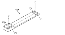
図5aは、本発明の一実施例による第1誘導部材170Aを示す斜視図である。
FIG. 5a is a perspective view illustrating a
図5aを参照すれば、第1誘導部材170Aは、一側部171に第1開放部171aを有し、他側部173に第2開放部173aを有するダクト(duct)形態からなることができる。
Referring to FIG. 5a, the
前記一側部171は、第1開放部171aが第1集電体120のヒューズ領域126a、126bまたは126cと対向するように第1集電体120と連結される。前記他側部173の第2開放部173aは、第1短絡部材160と対向し、第1短絡部材160の方向に延長および突出した形態からなる。したがって、ヒューズ領域126a、126bまたは126cに発生するガスは、ヒューズ領域126a、126bまたは126cが位置するFから第1誘導部材170Aを通じて前記第1短絡部材160が位置するF’方向に移動でき、前記他側部173の突出した構造を利用して、アークガスによる圧力を前記第1短絡部材160により集中的に加える。このとき、前記他側部173は前記第1短絡部材160とキャッププレート151の下面と所定の間隔をおいて離隔する。2次電池100に過充電が発生する場合にも内圧上昇によって前記第1短絡部材160が動作しなければならないので、前記他側部173とキャッププレート151とが離隔してケース140の内部と第1短絡部材160を連結する空間を提供するのが望ましい。
The one
前記第1誘導部材170Aは電極組立体110とキャッププレート151との間に位置することができる。そのために、前記第1誘導部材170Aは電極組立体110がケース140内部で移動するのを防止することができる。また、第1集電体120のヒューズ領域と第1短絡部材160の最短距離上に位置しているため、外部短絡時により迅速に第1短絡部材160を動作させることができる。
The
図5bは、本発明の一実施例による第2誘導部材170Bを示す斜視図である。 FIG. 5b is a perspective view illustrating a second guide member 170B according to an embodiment of the present invention.
図5bを参照すれば、第2誘導部材170Bは、一側部171に第1開放部171bを有し、他側部175に第2開放部175bを有するダクト(duct)形態からなることができる。
Referring to FIG. 5B, the second guide member 170B may have a duct shape having a
前記一側部171は、第1開放部171bが第1集電体120のヒューズ領域126a、126bまたは126cと対向するように第1集電体120と連結されることができる。前記他側部175の第2開放部175bは、第1短絡部材160と対向するように形成されることができる。したがって、ヒューズ領域126a、126bまたは126cに発生するガスは、ヒューズ領域126a、126bまたは126cが位置するFから第2誘導部材170Bを通じて前記第1短絡部材160が位置するF’方向に移動することができる。前記第2誘導部材170Bの他側部175は、前記第1誘導部材170Bとは異なり、平らな構造からなることができる。また、前記第2誘導部材170Bの他側部175は、前記第1誘導部材170Aの他側部173と同様に、前記第1短絡部材160とキャッププレート151の下面と所定の間隔をおいて離隔する。前記第1誘導部材170Aと比較して、第2誘導部材170Bは、ケース140の内部と第1短絡部材160を連結する空間をさらに提供することによって、過充電時に第1短絡部材160がより敏感に反応できることになる。
The one
図5cは、本発明の一実施例による第3誘導部材170Cを示す斜視図である。
FIG. 5c is a perspective view illustrating a
図5cを参照すれば、第3誘導部材170Cは、一側部171に第1開放部171aを有し、他側部177に第2開放部177C1および第3開放部177C2、177C3を有するダクト(duct)形態からなることができる。
Referring to FIG. 5c, the
前記一側部171は、第1開放部171aが第1集電体120のヒューズ領域126a、126bまたは126cと対向するように第1集電体120と連結されることができる。前記他側部177は、前記第2開放部177C1が前記第1短絡部材160と対向するように突出した構造からなることができる。したがって、ヒューズ領域126a、126bまたは126cに発生するガスは、ヒューズ領域126a、126bまたは126cが位置するFから第3誘導部材170Cを通じて前記第1短絡部材160が位置するF’方向に移動することができる。前記第3開放部177C2、177C3は前記他側部177の側面にそれぞれ形成されることができるが、本発明の実施例は前記第3開放部177C2、177C3の位置を限定するものではない。このような第3開放部177C2、177C3は、少なくとも一つ以上形成されて、ケース140内部と第1短絡部材160を連結する空間を提供することができる。前記第3開放部177C2、177C3によって前記他側部177から相対的に突出した部分177P1、177P2が形成されることができる。このように、前記他側部177から突出した部分177P1、177P2はキャッププレート151の下面と連結しているので、前記誘導部材170Cの他側部177がキャッププレート151に固定されることができる。
The one
前記第1ないし第3誘導部材170A、170B、170Cのうちのいずれか一つは電極組立体110とキャッププレート151との間に位置することができる。したがって、誘導部材の厚さと幅は、2次電池100の全体の大きさに影響を与えないように設計することが好ましく、本発明は前記第1ないし第3誘導部材170A、170B、170Cのサイズに限定されない。
Any one of the first to
本発明は、上記実施例に限定されず、本発明の技術的要旨から逸脱しない範囲内で様々に修正、変形されて実施され得ることは本発明の属する技術分野における通常の知識を有する者にとっては自明である。 The present invention is not limited to the above-described embodiments, and various modifications and changes can be made without departing from the technical scope of the present invention. For those skilled in the art to which the present invention pertains, Is self-explanatory.
100 2次電池
110 電極組立体
120 第1集電体
125 ヒューズホール
126a、126b、126c ヒューズ領域
130 第2集電体
140 ケース
150 キャップ組立体
160 第1短絡部材
161 第2短絡部材
170 誘導部材
100
Claims (7)
前記第1電極板と電気的に連結され、ヒューズ領域を有する第1集電体;
前記電極組立体および前記第1集電体を収容するケース;
前記ケースの開口を密封し、短絡ホールを有するキャッププレート;
前記短絡ホールに設けられ、前記第1電極板と電気的に連結されている第1短絡部材;
前記キャッププレートの上面から離隔し、前記第1短絡部材と向かい合って前記第2電極板と電気的に連結される第2短絡部材;および
前記ケース内部で、前記ヒューズ領域で発生するガスを前記第1短絡部材に誘導する誘導部材を含み、
前記第1短絡部材は、
予め設定された圧力より大きな圧力を受けると形態が反転して、前記第2短絡部材と電気的に接触するように形成されることを特徴とする2次電池。 An electrode assembly including a first electrode plate, a second electrode plate, and a separator interposed between the first electrode plate and the second electrode plate;
A first current collector electrically connected to the first electrode plate and having a fuse region;
A case for housing the electrode assembly and the first current collector;
A cap plate sealing the opening of the case and having a short-circuit hole;
A first short-circuit member provided in the short-circuit hole and electrically connected to the first electrode plate ;
A second short-circuit member spaced apart from an upper surface of the cap plate and facing the first short-circuit member and electrically connected to the second electrode plate; and a gas generated in the fuse region within the case. the guide member to induce the 1 short-circuit member seen including,
The first short-circuit member is
A secondary battery, wherein the battery is formed so as to reverse its form when it receives a pressure greater than a preset pressure and to be in electrical contact with the second short-circuit member .
一側部に第1開放部を有し、他側部に第2開放部を有するダクト(duct)形態からなることを特徴とする請求項1に記載の2次電池。 The guide member is
The secondary battery according to claim 1, wherein the secondary battery has a duct shape having a first open portion on one side and a second open portion on the other side.
前記第1開放部が、前記ヒューズ領域と対向するように前記第1集電体と連結されることを特徴とする請求項2に記載の2次電池。 One side of the guide member is
The secondary battery according to claim 2, wherein the first open part is connected to the first current collector so as to face the fuse region.
前記第2開放部が、前記第1短絡部材と対向し、前記第1短絡部材および前記キャッププレートの下面と離隔していることを特徴とする請求項2に記載の2次電池。 The other side of the guide member is
3. The secondary battery according to claim 2, wherein the second opening portion faces the first short-circuit member and is spaced apart from the first short-circuit member and the lower surface of the cap plate.
前記第1短絡部材に向かって突出する形態からなることを特徴とする請求項4に記載の2次電池。 The other side of the guide member is
The secondary battery according to claim 4, wherein the secondary battery is configured to protrude toward the first short-circuit member.
前記第2開放部が前記第1短絡部材に向かうように突出して前記キャッププレートの下面と連結され、
前記誘導部材の他側部の突出部分は、
前記ケース内部と通じる少なくとも一つ以上の第3開放部を有することを特徴とする請求項2に記載の2次電池。 The other side of the guide member is
The second open part protrudes toward the first short-circuit member and is connected to the lower surface of the cap plate;
The protruding portion on the other side of the guide member is
The secondary battery according to claim 2, further comprising at least one third open portion that communicates with the inside of the case.
前記第1集電体の他の領域より断面積が小さいことを特徴とする請求項1に記載の2次電池。 The fuse region is
The secondary battery according to claim 1, wherein a cross-sectional area is smaller than that of the other region of the first current collector.
Applications Claiming Priority (2)
| Application Number | Priority Date | Filing Date | Title |
|---|---|---|---|
| KR10-2012-0036292 | 2012-04-06 | ||
| KR1020120036292A KR101715963B1 (en) | 2012-04-06 | 2012-04-06 | Secondary bttery |
Publications (2)
| Publication Number | Publication Date |
|---|---|
| JP2013219003A JP2013219003A (en) | 2013-10-24 |
| JP6091815B2 true JP6091815B2 (en) | 2017-03-08 |
Family
ID=47018853
Family Applications (1)
| Application Number | Title | Priority Date | Filing Date |
|---|---|---|---|
| JP2012196922A Active JP6091815B2 (en) | 2012-04-06 | 2012-09-07 | Secondary battery |
Country Status (5)
| Country | Link |
|---|---|
| US (1) | US9490468B2 (en) |
| EP (1) | EP2648246B1 (en) |
| JP (1) | JP6091815B2 (en) |
| KR (1) | KR101715963B1 (en) |
| CN (1) | CN103367688B (en) |
Families Citing this family (23)
| Publication number | Priority date | Publication date | Assignee | Title |
|---|---|---|---|---|
| US9225002B2 (en) * | 2013-10-24 | 2015-12-29 | Samsung Sdi Co., Ltd. | Rechargeable battery having fuse unit |
| KR102119049B1 (en) * | 2013-12-16 | 2020-06-04 | 삼성에스디아이 주식회사 | Rechargeable battery having insulation case |
| KR102273768B1 (en) * | 2014-04-01 | 2021-07-06 | 삼성에스디아이 주식회사 | Secondary battery |
| KR102226513B1 (en) * | 2014-06-02 | 2021-03-11 | 삼성에스디아이 주식회사 | Secondary battery |
| US10008710B2 (en) | 2014-08-04 | 2018-06-26 | Johnson Controls Technology Company | Overcharge protection assembly for a battery module |
| KR102332447B1 (en) | 2015-02-26 | 2021-11-26 | 삼성에스디아이 주식회사 | Rechargeable battery |
| JP6328842B2 (en) * | 2015-02-27 | 2018-05-23 | 三洋電機株式会社 | Power supply device and vehicle equipped with the same |
| KR101733745B1 (en) * | 2015-04-07 | 2017-05-08 | 삼성에스디아이 주식회사 | Rechargeable battery |
| KR102371192B1 (en) * | 2015-08-07 | 2022-03-07 | 삼성에스디아이 주식회사 | A secondary battery |
| KR102371193B1 (en) * | 2015-08-10 | 2022-03-07 | 삼성에스디아이 주식회사 | Secondary Battery |
| WO2017171002A1 (en) * | 2016-03-31 | 2017-10-05 | 株式会社 豊田自動織機 | Electric storage device |
| US11233289B2 (en) | 2016-08-01 | 2022-01-25 | Cps Technology Holdings Llc | Weldable aluminum terminal pads of an electrochemical cell |
| CN115020790A (en) | 2016-08-01 | 2022-09-06 | Cps 科技控股有限公司 | Overcharge protection system for prismatic lithium ion battery cells with bias packaging |
| WO2018026728A1 (en) | 2016-08-01 | 2018-02-08 | Johnson Controls Technology Company | Overcharge protection assembly for a battery cell |
| CN109891635B (en) * | 2016-10-24 | 2022-02-18 | 三洋电机株式会社 | Square secondary battery |
| CN109792029B (en) * | 2016-11-15 | 2021-08-03 | 宁德时代新能源科技股份有限公司 | Secondary battery and battery module |
| CN108807827A (en) * | 2017-04-28 | 2018-11-13 | 比亚迪股份有限公司 | A kind of electrode leading-out sheet and battery |
| JP6955387B2 (en) * | 2017-08-03 | 2021-10-27 | 株式会社Gsユアサ | Power storage device |
| JP6962167B2 (en) * | 2017-12-12 | 2021-11-05 | 三洋電機株式会社 | Rechargeable battery |
| CN109037761A (en) * | 2018-07-17 | 2018-12-18 | 江苏海基新能源股份有限公司 | A kind of rectangular lithium ion battery with aluminum shell and assembly method |
| JP7442269B2 (en) | 2019-03-29 | 2024-03-04 | 三洋電機株式会社 | secondary battery |
| JPWO2021060006A1 (en) | 2019-09-26 | 2021-04-01 | ||
| CN114207932A (en) | 2019-09-26 | 2022-03-18 | 三洋电机株式会社 | Secondary battery |
Family Cites Families (12)
| Publication number | Priority date | Publication date | Assignee | Title |
|---|---|---|---|---|
| FR2761815B1 (en) * | 1997-03-24 | 1999-09-24 | Alsthom Cge Alcatel | ELECTROCHEMICAL GENERATOR WITH SPIRAL ELECTRODES WITH IMPROVED SAFETY IN THE EVENT OF GASEOUS RELEASE |
| JP2000077058A (en) * | 1998-08-31 | 2000-03-14 | Alps Electric Co Ltd | Electric circuit breaking mechanism of battery |
| KR101380029B1 (en) * | 2006-10-13 | 2014-04-02 | 파나소닉 주식회사 | Battery pack, battery-mounted device and connection structure for battery pack |
| WO2008051219A1 (en) | 2006-10-23 | 2008-05-02 | Utc Fuel Cells, Llc | Electrode substrate for electrochemical cell from carbon and cross-linkable resin fibers |
| FR2910723B1 (en) | 2006-12-22 | 2009-03-20 | Accumulateurs Fixes | SECURITY DEVICE FOR SEALED ACCUMULATOR. |
| US9413031B2 (en) * | 2009-03-24 | 2016-08-09 | Lenovo (Singapore) Pte. Ltd. | Apparatus and system for an internal fuse in a battery cell |
| KR101072956B1 (en) * | 2009-03-30 | 2011-10-12 | 에스비리모티브 주식회사 | Rechargeable battery |
| KR101097220B1 (en) * | 2009-10-30 | 2011-12-21 | 에스비리모티브 주식회사 | Secondary battery |
| US8440336B2 (en) * | 2009-12-08 | 2013-05-14 | Samsung Sdi Co., Ltd. | Rechargeable battery with short circuit member |
| KR101042808B1 (en) * | 2010-01-26 | 2011-06-20 | 에스비리모티브 주식회사 | Rechargeable battery |
| US9099732B2 (en) * | 2010-06-11 | 2015-08-04 | Samsung Sdi Co., Ltd. | Rechargeable battery having a fuse with an insulating blocking member |
| US20120052341A1 (en) * | 2010-09-01 | 2012-03-01 | Duk-Jung Kim | Rechargeable battery |
-
2012
- 2012-04-06 KR KR1020120036292A patent/KR101715963B1/en active IP Right Grant
- 2012-09-07 JP JP2012196922A patent/JP6091815B2/en active Active
- 2012-10-05 EP EP12187335.0A patent/EP2648246B1/en active Active
- 2012-11-09 US US13/673,082 patent/US9490468B2/en active Active
- 2012-11-26 CN CN201210488386.6A patent/CN103367688B/en active Active
Also Published As
| Publication number | Publication date |
|---|---|
| CN103367688A (en) | 2013-10-23 |
| KR101715963B1 (en) | 2017-03-27 |
| CN103367688B (en) | 2017-09-01 |
| EP2648246A1 (en) | 2013-10-09 |
| KR20130113802A (en) | 2013-10-16 |
| JP2013219003A (en) | 2013-10-24 |
| EP2648246B1 (en) | 2015-04-15 |
| US20130266830A1 (en) | 2013-10-10 |
| US9490468B2 (en) | 2016-11-08 |
Similar Documents
| Publication | Publication Date | Title |
|---|---|---|
| JP6091815B2 (en) | Secondary battery | |
| JP5441072B2 (en) | Secondary battery | |
| KR101274806B1 (en) | Rechargeable battery | |
| JP6491817B2 (en) | Secondary battery | |
| JP6158474B2 (en) | Secondary battery | |
| EP2403036B1 (en) | Rechargeable battery | |
| US8617737B2 (en) | Rechargeable battery | |
| JP6491448B2 (en) | Secondary battery and battery module | |
| US8647759B2 (en) | Secondary battery | |
| US10826048B2 (en) | Secondary battery | |
| US9478789B2 (en) | Rechargeable battery | |
| KR101675618B1 (en) | Secondary battery | |
| KR101695992B1 (en) | Secondary battery | |
| US20130337295A1 (en) | Rechargeable battery | |
| US8999539B2 (en) | Secondary battery including short circuit member comprising duct part and deformable part | |
| KR102337494B1 (en) | Secondary battery | |
| US9577229B2 (en) | Secondary battery | |
| KR101715955B1 (en) | Secondary bttery |
Legal Events
| Date | Code | Title | Description |
|---|---|---|---|
| RD04 | Notification of resignation of power of attorney |
Free format text: JAPANESE INTERMEDIATE CODE: A7424 Effective date: 20141226 |
|
| A621 | Written request for application examination |
Free format text: JAPANESE INTERMEDIATE CODE: A621 Effective date: 20150622 |
|
| A977 | Report on retrieval |
Free format text: JAPANESE INTERMEDIATE CODE: A971007 Effective date: 20160526 |
|
| A131 | Notification of reasons for refusal |
Free format text: JAPANESE INTERMEDIATE CODE: A131 Effective date: 20160530 |
|
| A521 | Request for written amendment filed |
Free format text: JAPANESE INTERMEDIATE CODE: A523 Effective date: 20160829 |
|
| TRDD | Decision of grant or rejection written | ||
| A01 | Written decision to grant a patent or to grant a registration (utility model) |
Free format text: JAPANESE INTERMEDIATE CODE: A01 Effective date: 20170110 |
|
| A61 | First payment of annual fees (during grant procedure) |
Free format text: JAPANESE INTERMEDIATE CODE: A61 Effective date: 20170208 |
|
| R150 | Certificate of patent or registration of utility model |
Ref document number: 6091815 Country of ref document: JP Free format text: JAPANESE INTERMEDIATE CODE: R150 |
|
| R250 | Receipt of annual fees |
Free format text: JAPANESE INTERMEDIATE CODE: R250 |
|
| R250 | Receipt of annual fees |
Free format text: JAPANESE INTERMEDIATE CODE: R250 |
|
| R250 | Receipt of annual fees |
Free format text: JAPANESE INTERMEDIATE CODE: R250 |
|
| R250 | Receipt of annual fees |
Free format text: JAPANESE INTERMEDIATE CODE: R250 |
|
| R250 | Receipt of annual fees |
Free format text: JAPANESE INTERMEDIATE CODE: R250 |