JP6090335B2 - Information processing device - Google Patents
Information processing device Download PDFInfo
- Publication number
- JP6090335B2 JP6090335B2 JP2014557217A JP2014557217A JP6090335B2 JP 6090335 B2 JP6090335 B2 JP 6090335B2 JP 2014557217 A JP2014557217 A JP 2014557217A JP 2014557217 A JP2014557217 A JP 2014557217A JP 6090335 B2 JP6090335 B2 JP 6090335B2
- Authority
- JP
- Japan
- Prior art keywords
- system board
- partition
- information
- configuration
- unit
- Prior art date
- Legal status (The legal status is an assumption and is not a legal conclusion. Google has not performed a legal analysis and makes no representation as to the accuracy of the status listed.)
- Expired - Fee Related
Links
- 230000010365 information processing Effects 0.000 title claims description 33
- 238000005192 partition Methods 0.000 claims description 186
- 238000010276 construction Methods 0.000 claims 1
- 238000011084 recovery Methods 0.000 description 46
- 230000006870 function Effects 0.000 description 36
- 238000010586 diagram Methods 0.000 description 16
- 238000000034 method Methods 0.000 description 14
- 238000012544 monitoring process Methods 0.000 description 13
- 238000012545 processing Methods 0.000 description 11
- 238000005516 engineering process Methods 0.000 description 3
- 230000008569 process Effects 0.000 description 3
- 230000008859 change Effects 0.000 description 2
- 238000004891 communication Methods 0.000 description 1
- 238000012790 confirmation Methods 0.000 description 1
- 238000001514 detection method Methods 0.000 description 1
- 230000000694 effects Effects 0.000 description 1
- 230000002093 peripheral effect Effects 0.000 description 1
- 230000001172 regenerating effect Effects 0.000 description 1
- 230000008439 repair process Effects 0.000 description 1
- 230000004044 response Effects 0.000 description 1
Images


Classifications
-
- G—PHYSICS
- G06—COMPUTING; CALCULATING OR COUNTING
- G06F—ELECTRIC DIGITAL DATA PROCESSING
- G06F11/00—Error detection; Error correction; Monitoring
- G06F11/07—Responding to the occurrence of a fault, e.g. fault tolerance
- G06F11/16—Error detection or correction of the data by redundancy in hardware
- G06F11/20—Error detection or correction of the data by redundancy in hardware using active fault-masking, e.g. by switching out faulty elements or by switching in spare elements
- G06F11/202—Error detection or correction of the data by redundancy in hardware using active fault-masking, e.g. by switching out faulty elements or by switching in spare elements where processing functionality is redundant
- G06F11/2023—Failover techniques
- G06F11/2025—Failover techniques using centralised failover control functionality
-
- G—PHYSICS
- G06—COMPUTING; CALCULATING OR COUNTING
- G06F—ELECTRIC DIGITAL DATA PROCESSING
- G06F11/00—Error detection; Error correction; Monitoring
- G06F11/07—Responding to the occurrence of a fault, e.g. fault tolerance
- G06F11/16—Error detection or correction of the data by redundancy in hardware
- G06F11/20—Error detection or correction of the data by redundancy in hardware using active fault-masking, e.g. by switching out faulty elements or by switching in spare elements
- G06F11/202—Error detection or correction of the data by redundancy in hardware using active fault-masking, e.g. by switching out faulty elements or by switching in spare elements where processing functionality is redundant
- G06F11/2023—Failover techniques
- G06F11/2028—Failover techniques eliminating a faulty processor or activating a spare
-
- G—PHYSICS
- G06—COMPUTING; CALCULATING OR COUNTING
- G06F—ELECTRIC DIGITAL DATA PROCESSING
- G06F11/00—Error detection; Error correction; Monitoring
- G06F11/07—Responding to the occurrence of a fault, e.g. fault tolerance
- G06F11/16—Error detection or correction of the data by redundancy in hardware
- G06F11/20—Error detection or correction of the data by redundancy in hardware using active fault-masking, e.g. by switching out faulty elements or by switching in spare elements
- G06F11/202—Error detection or correction of the data by redundancy in hardware using active fault-masking, e.g. by switching out faulty elements or by switching in spare elements where processing functionality is redundant
- G06F11/2023—Failover techniques
- G06F11/203—Failover techniques using migration
-
- G—PHYSICS
- G06—COMPUTING; CALCULATING OR COUNTING
- G06F—ELECTRIC DIGITAL DATA PROCESSING
- G06F11/00—Error detection; Error correction; Monitoring
- G06F11/07—Responding to the occurrence of a fault, e.g. fault tolerance
- G06F11/16—Error detection or correction of the data by redundancy in hardware
- G06F11/20—Error detection or correction of the data by redundancy in hardware using active fault-masking, e.g. by switching out faulty elements or by switching in spare elements
- G06F11/202—Error detection or correction of the data by redundancy in hardware using active fault-masking, e.g. by switching out faulty elements or by switching in spare elements where processing functionality is redundant
- G06F11/2041—Error detection or correction of the data by redundancy in hardware using active fault-masking, e.g. by switching out faulty elements or by switching in spare elements where processing functionality is redundant with more than one idle spare processing component
-
- G—PHYSICS
- G06—COMPUTING; CALCULATING OR COUNTING
- G06F—ELECTRIC DIGITAL DATA PROCESSING
- G06F11/00—Error detection; Error correction; Monitoring
- G06F11/07—Responding to the occurrence of a fault, e.g. fault tolerance
- G06F11/16—Error detection or correction of the data by redundancy in hardware
- G06F11/20—Error detection or correction of the data by redundancy in hardware using active fault-masking, e.g. by switching out faulty elements or by switching in spare elements
- G06F11/202—Error detection or correction of the data by redundancy in hardware using active fault-masking, e.g. by switching out faulty elements or by switching in spare elements where processing functionality is redundant
- G06F11/2048—Error detection or correction of the data by redundancy in hardware using active fault-masking, e.g. by switching out faulty elements or by switching in spare elements where processing functionality is redundant where the redundant components share neither address space nor persistent storage
Landscapes
- Engineering & Computer Science (AREA)
- Theoretical Computer Science (AREA)
- Quality & Reliability (AREA)
- Physics & Mathematics (AREA)
- General Engineering & Computer Science (AREA)
- General Physics & Mathematics (AREA)
- Hardware Redundancy (AREA)
Description
本発明は、情報処理装置、情報処理装置制御方法及び情報処理装置制御プログラムに関する。 The present invention relates to an information processing apparatus, an information processing apparatus control method, and an information processing apparatus control program.
基幹システムで運用されるサーバでは、高い可用性や柔軟なリソース運用が要求される。例えば、システムの高可用性を実現するための機能の一つとしてReservedSB(System Board)機能がある。 High availability and flexible resource operation are required for servers operated in the core system. For example, there is a Reserved SB (System Board) function as one of the functions for realizing high availability of the system.
ReservedSB機能を有するサーバには、筐体内に予備のシステムボード(System Board:SB)が実装されている。ReservedSB機能は、運用中のシステムボードに障害が発生した場合、障害が発生したシステムボードを自立的に切り離し、予備のシステムボードを短時間で組み込むことで、障害が発生したシステムボードを新しいシステムボードに切替える。ここで、システムボードとはCPU(Central Processing Unit)とメモリを搭載しているボードである。また、障害発生時に切替え先の対象となる予備のシステムボードをReservedSBと呼ぶ。 In a server having a Reserved SB function, a spare system board (SB) is mounted in a housing. The Reserved SB function automatically disconnects a failed system board and installs a spare system board in a short time when a failure occurs in the operating system board. Switch to. Here, the system board is a board on which a CPU (Central Processing Unit) and a memory are mounted. Also, a spare system board that is the target of switching when a failure occurs is referred to as ReservedSB.
ReservedSB機能を利用すると、システムボード上でハードウェア障害が発生した場合、システムボード資源が減少せず、障害発生前と同じ状態での早期復旧が可能である。 When the Reserved SB function is used, when a hardware failure occurs on the system board, the system board resources are not reduced, and an early recovery in the same state as before the failure occurs is possible.
また、可用性を向上させる技術として、1つの筐体内を複数の論理システムに分割し複数のサーバを格納しているように取り扱う技術がある。具体的には、1つの筐体内をシステムボード及びI/O(Input/Output)ユニットの組(以下では、この組を「パーティション」と呼ぶ。)に分割し、分割した各パーティションを1つ論理システムとして独立して動作させる機能である。各パーティションにはOS(Operation System)及びアプリケーションなどのソフトウェア資源、並びに、システムボード及びI/Oユニットなどのハードウェア資源が含まれる。ここで、1つのパーティションの中には、複数のシステムボードが含まれていてもよいし、複数のI/Oユニットが含まれていてもよい。また、I/Oユニットには、ハードディスク及びネットワークカードなどが含まれる。このように、パーティション構成を採用しておけば、あるパーティションに障害が発生しても他のパーティションには影響が及ばない。 In addition, as a technique for improving availability, there is a technique for handling a case in which a single housing is divided into a plurality of logical systems and a plurality of servers are stored. Specifically, one housing is divided into a set of system boards and I / O (Input / Output) units (hereinafter, this set is referred to as a “partition”), and each divided partition is logically divided into one. This function allows the system to operate independently. Each partition includes software resources such as OS (Operation System) and applications, and hardware resources such as system boards and I / O units. Here, a plurality of system boards may be included in one partition, or a plurality of I / O units may be included. The I / O unit includes a hard disk and a network card. Thus, if a partition configuration is adopted, even if a failure occurs in one partition, the other partitions are not affected.
さらに、上述したパーティション構成とReservedSB機能とを組み合わせることで、より可用性の高いシステムを構築することが考えられる。 Furthermore, it is conceivable to construct a system with higher availability by combining the partition configuration described above and the Reserved SB function.
例えば、ある1つの筐体内部に複数のパーティションを作成して運用系とし、さらにパーティションとして構成されていないシステムボードやI/Oユニットを待機系とする。ここで、運用系のシステムボードに切替え先となるシステムボードであるReservedSBを割り当てて置く。このReservedSBは、待機系のシステムボードでもよいし、ReservedSBが割り当てられるシステムボードを含むパーティション以外の他のパーティションに複数のシステムボードが含まれる場合、その内の一つのシステムボードであってもよい。そして、あるパーティションのシステムボードに故障が発生した場合、その故障したシステムボードに割り当てられているReservedSBに切替えてパーティションの運用を継続することが考えられる。ここで、例えば、ReservedSBが他のパーティションに含まれるシステムボードの場合には、ReservedSBをそのパーティションから分離させ、故障が発生したシステムボードと切替えて運用を継続することが考えられる。 For example, a plurality of partitions are created in a certain housing to be an active system, and a system board or I / O unit that is not configured as a partition is a standby system. Here, the Reserved SB which is the system board to be switched to is assigned to the active system board. This Reserved SB may be a standby system board, or when a plurality of system boards are included in a partition other than the partition including the system board to which the Reserved SB is allocated, it may be one of the system boards. When a failure occurs in a system board in a certain partition, it is conceivable to switch to the Reserved SB assigned to the failed system board and continue the operation of the partition. Here, for example, when the Reserved SB is a system board included in another partition, it is conceivable that the Reserved SB is separated from the partition, and the operation is continued by switching to the system board in which the failure has occurred.
このように、パーティション構成とReservedSB機能とを組み合わせたシステムにおいては、システムボードの切替えが発生した後、故障したシステムボードの保守交換を行った場合、障害発生前のパーティションの構成に復帰させることが考えられる。これには、次のような理由がある。まず、当初設定した運用ポリシーの構成でシステムを運用させることが好ましい場合がある。例えば、複数の筐体で同じ運用ポリシーでパーティションを構成している場合に、故障が発生した筐体だけ構成が異なってしまっては、管理上の不便が生じてしまうおそれがある。また、ReservedSBとして使用する予備のシステムボードは、短時間での復旧を実現するための一次的な代用品であり、継続して使用し続けるには十分なスペックが無いことが考えられる。さらには、他のパーティションのシステムボードに切替えを行った場合には、他のパーティションのパフォーマンスが下がった状態が継続してしまうおそれがある。 In this way, in a system that combines the partition configuration and the Reserved SB function, when a failed system board is maintained and replaced after a system board switchover, the partition configuration before the failure can be restored. Conceivable. There are the following reasons for this. First, it may be preferable to operate the system with the configuration of the initially set operation policy. For example, in the case where a partition is configured with the same operation policy in a plurality of casings, there is a possibility that management inconvenience may occur if the configuration of only the casing in which a failure occurs is different. In addition, a spare system board used as a Reserved SB is a primary substitute for realizing recovery in a short time, and it is considered that there is not enough specifications to continue to use it. Furthermore, when switching to the system board of another partition, there is a possibility that the state where the performance of the other partition is lowered continues.
システム構成の変更に関する従来技術として、起動時からシステム構成に変更があった場合、変更後のシステム構成が過去に採用した構成であれば、システム構成に関する情報を再度生成せずに過去の情報を利用する技術がある(例えば、特許文献1参照)。 As a conventional technology related to system configuration changes, if there is a change in the system configuration since startup, if the system configuration after the change has been adopted in the past, the past information is not generated without regenerating the system configuration information. There is a technique to use (see, for example, Patent Document 1).
しかしながら、単にパーティション構成とReservedSB機能とを組み合わせた場合、ReservedSBの設定情報やパーティションの構成情報は、システムボードの切替えが発生した後に残らない。そのため、管理者はシステムボードの切替え発生後、故障したシステムボードの修理を行い、障害発生前のパーティションの構成に復帰させるために次のような作業を行っていた。まず、管理者は、システムイベントログを解析するなどしてReservedSBの設定情報やパーティションの構成情報を取得する。そして、取得した情報を用いて、管理者は、修理を行ったシステムボードを元のパーティションに組み込む。さらに、管理者は、障害発生前の設定状態になるようにReservedSBの再設定を行う。以上の作業を行うことで、障害発生前の状態に戻すことができる。 However, when the partition configuration and the Reserved SB function are simply combined, the setting information of the Reserved SB and the configuration information of the partition do not remain after the system board is switched. For this reason, after switching the system board, the administrator repairs the failed system board and performs the following work to return to the partition configuration before the failure. First, the administrator obtains Reserved SB setting information and partition configuration information by analyzing a system event log. Then, using the acquired information, the administrator incorporates the repaired system board into the original partition. Furthermore, the administrator resets the Reserved SB so that the setting state before the failure occurs is obtained. By performing the above operations, it is possible to return to the state before the occurrence of the failure.
このように、システムイベントログの解析、パーティションの再構成及びReservedSBの再設定を行うことは煩雑であり、また、作業過程において人為的ミスが発生するおそれもある。 As described above, it is complicated to analyze the system event log, reconfigure the partition, and reset the Reserved SB, and there is a possibility that a human error occurs in the work process.
また、システム構成に関する情報として過去の情報を利用する従来技術ではパーティションの構成などは考慮されておらず、障害復旧後にパーティションの再構成及びResevedSBの再設定を自動で行うことは困難である。 Further, in the conventional technology that uses past information as information regarding the system configuration, the configuration of the partition is not considered, and it is difficult to automatically perform the partition reconfiguration and the reset of the Reserved SB after the failure recovery.
開示の技術は、上記に鑑みてなされたものであって、パーティションを有するシステムを障害発生前の構成に自動的に戻す情報処理装置、情報処理装置制御方法及び情報処理装置制御プログラムを提供することを目的とする。 The disclosed technology has been made in view of the above, and provides an information processing apparatus, an information processing apparatus control method, and an information processing apparatus control program for automatically returning a system having a partition to a configuration before the occurrence of a failure. With the goal.
本願の開示する情報処理装置、情報処理装置制御方法及び情報処理装置制御プログラムは、一つの態様において、構成部は、一つの筐体の中に搭載された、CPU及びメモリを搭載するシステムボードと、I/Oデバイスを搭載するI/Oユニットとの組合せであるパーティションの構成及び前記パーティションに対する予備のシステムボードの割り当てを行う。切替部は、障害が発生した障害発生システムボードがある場合に、前記障害発生システムボードを、前記障害発生システムボードを含むパーティションに割り当てられた予備のシステムボードに切替え、且つ、前記障害発生システムボードと切替先の前記予備のシステムボードとの対応を示す切替後構成情報を生成する。再設定部は、自己による前記パーティションの構成及び前記予備のシステムボードの割り当てを示す前記障害の発生前のパーティションの障害前構成情報を記憶し、前記切替部によるシステムボードの切替えが行われた後、前記障害発生システムボードが復旧した場合、前記切替後構成情報に含まれる前記障害発生システムボードの情報と切替先の前記予備のシステムボードの情報の中に、復旧した前記障害発生システムボードの情報及び復旧した前記障害発生システムボードに対応する前記予備のシステムボードの情報が存在する場合、復旧した前記障害発生システムボードが前記予備のシステムボードに切り替わっていると判定し、前記障害前構成情報を基に、前記パーティションの構成及び前記予備のシステムボードの割り当てを再設定する。 In one aspect, an information processing apparatus, an information processing apparatus control method, and an information processing apparatus control program disclosed in the present application are configured such that a configuration unit includes a system board that is mounted in a single housing and includes a CPU and a memory. The configuration of the partition, which is a combination with the I / O unit on which the I / O device is mounted, and the spare system board are allocated to the partition. When there is a faulty system board in which a fault has occurred, the switching unit switches the faulty system board to a spare system board assigned to a partition including the faulty system board , and the faulty system board and that generates a switching after the configuration information indicating a correspondence between the switching destination of the spare system board. The resetting unit stores the pre-failure configuration information of the partition before the failure, which indicates the configuration of the partition by itself and the allocation of the spare system board, and after the system board is switched by the switching unit When the failed system board is recovered, the recovered failed system board information is included in the failed system board information and the switched system board information included in the post-switching configuration information. And when there is information on the spare system board corresponding to the restored faulty system board, it is determined that the restored faulty system board has been switched to the spare system board, and the pre-failure configuration information is Based on the above, reconfigure the partition configuration and the spare system board assignment. To.
本願の開示する情報処理装置、情報処理装置制御方法及び情報処理装置制御プログラムの一つの態様によれば、パーティションを有するシステムを障害発生前の構成に自動的に戻すことができるという効果を奏する。 According to one aspect of the information processing apparatus, the information processing apparatus control method, and the information processing apparatus control program disclosed in the present application, there is an effect that the system having the partition can be automatically returned to the configuration before the occurrence of the failure.
以下に、本願の開示する情報処理装置、情報処理装置制御方法及び情報処理装置制御プログラムの実施例を図面に基づいて詳細に説明する。なお、以下の実施例により本願の開示する情報処理装置、情報処理装置制御方法及び情報処理装置制御プログラムが限定されるものではない。 Embodiments of an information processing apparatus, an information processing apparatus control method, and an information processing apparatus control program disclosed in the present application will be described below in detail with reference to the drawings. The information processing apparatus, the information processing apparatus control method, and the information processing apparatus control program disclosed in the present application are not limited by the following embodiments.
図1は、実施例に係る情報処理システムの構成図である。図1に示すように、本実施例に係る情報処理システムは、サーバ管理装置1及びサーバ2を有する。ここで、本実施例では、サーバ2を1台のみ記載しているが、サーバ管理装置1は、複数のサーバ2を同時に管理することも可能である。 FIG. 1 is a configuration diagram of an information processing system according to the embodiment. As illustrated in FIG. 1, the information processing system according to the present embodiment includes a server management device 1 and a server 2. Here, in the present embodiment, only one server 2 is described, but the server management apparatus 1 can also manage a plurality of servers 2 at the same time.
サーバ2は、システムボード201〜204、I/O(Input/Output)スイッチ220及びIOU(Input Output Unit)211〜214を有している。
The server 2 includes
システムボード201〜204は、それぞれ、CPU(Central Processing Unit)21及びメモリ22を有している。図中では、分かり易いように、システムボードを「SB」として表している。本実施例では、システムボード201〜204のそれぞれは、複数のCPU21及びメモリ22を有している。また、本実施例では、サーバ2の中に4つのシステムボード201〜204が搭載されている構成で説明するが、システムボードの数は複数であればこれに限らない。以下では、システムボード201〜204のそれぞれを区別しない場合、単に「システムボード200」と表す。
Each of the
IOU211〜214は、ハードディスクドライブやPCI(Peripheral Component Interconnect)カードなどのI/Oデバイス23を搭載した装置である。以下では、IOU211〜214のそれぞれを区別しない場合、単に「IOU210」と表す。
The
I/Oスイッチ220は、システムボード200とIOU210とを接続するスイッチである。I/Oスイッチ220が特定のシステムボードと特定のIOUとを接続するように切り替わることで、特定のシステムボード上のCPU21と接続された特定のIOU上のI/Oデバイス23とがバスで接続される。これにより、CPU21は、接続先のIOU上のI/Oデバイス23を利用することができるようになる。例えば、I/Oスイッチ220が、システムボード201とIOU211とを接続するように切り替わった場合、システムボード201上のCPU21は、IOU211上のI/Oデバイス23を利用することが可能となる。
The I /
サーバ管理装置1は、管理者からの指示によるサーバ2の構成や、障害発生時のサーバ2の障害復旧などといったサーバ2の管理を行う。サーバ管理装置1は、サーバ2に搭載された各システムボード200、I/Oスイッチ220及び各IOU210のそれぞれと接続されている。ただし、図1では、分かり易いように接続をまとめて、サーバ管理装置1とサーバ2とが接続しているように表している。次に、図2を参照して、サーバ管理装置1について詳細に説明する。図2は、サーバ管理装置のブロック図である。
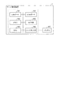
The server management apparatus 1 manages the server 2 such as the configuration of the server 2 according to an instruction from the administrator, and the failure recovery of the server 2 when a failure occurs. The server management apparatus 1 is connected to each system board 200, I /
図2に示すように、本実施例に係るサーバ管理装置1は、再設定部11、監視部12、切替部13、構成部14及び記憶部15を有している。
As illustrated in FIG. 2, the server management apparatus 1 according to the present embodiment includes a resetting unit 11, a
記憶部15は、不揮発性の記憶部であり、例えば、NVRAM(Non Volatile Random Access Memory)などである。
The
構成部14は、管理者からパーティション構成情報、リザーブSB情報及び自動復旧の指示の入力を受ける。例えば、管理者は、サーバ管理装置1のユーザインタフェース(不図示)又はネットワークを介してサーバ管理装置1に接続された端末を用いてパーティション構成情報、リザーブSB情報及び自動復旧の指示の入力を行う。パーティション構成情報には、システムボード200のうちのどれとIOU210のうちのどれとを組とするかという情報が含まれている。また、リザーブSB情報には、各パーティションに含まれるシステムボード200が故障したときのReservedSB機能により切替え先となるシステムボード(以下では、「リザーブSB」という。)の情報が含まれている。さらに、自動復旧の指示には、ReservedSB機能を用いてシステムボード200の切替えが発生した後、障害が発生したシステムボード200を修理又は交換などの障害対応を行った場合に、切替え前の構成に戻すか否かの指示が含まれる。そして、構成部14は、管理者から指示されたパーティション構成及び指定されたリザーブSBを有するように、システムボード200、I/Oスイッチ220及びIOU210を構成する。さらに、自動復旧を行う指示を受けた場合、構成部14は、記憶部15における自動復旧フラグをオンにする。例えば、自動復旧フラグとして、記憶部15における所定のビットを用いてもよい。さらに、構成部14は、パーティションの構成及びリザーブSBの設定の情報を切替部13に通知する。
The
例えば、本実施例では、構成部14は、パーティションの構成としてシステムボード201とIOU211とが1つのパーティションを構成し、システムボード202とIOU212と1つのパーティションを構成するというパーティション構成情報の入力を受ける。また、構成部14は、リザーブSB情報として、システムボード203及びシステムボード204を、パーティション301のシステムボード201のリザーブSBとする情報の入力を受ける。さらに、構成部14は、リザーブSB情報として、システムボード203及びシステムボード204をパーティション302のシステムボード202のリザーブSBとする情報の入力を受ける。
For example, in the present embodiment, the
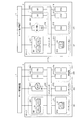
図3は、パーティション構成の一例の図である。この場合、構成部14は、図3に示すように、システムボード201及びIOU211でパーティション301を構成する。例えば、構成部14は、システムボード201とIOU211とを接続するようにI/Oスイッチ220を制御する。さらに、構成部14は、システムボード201のCPU21に対して、IOU211のI/Oデバイス23のみを使用するように指示する。同様に、構成部14は、システムボード202及びIOU212でパーティション302を構成する。ここで、システムボード203及び204、並びに、IOU213及び214はパーティションの構成要素として割り当てられていない。パーティションに割り当てられていないシステムボードやIOUは処理を行わない。この状態では、システムボード203及び204、並びに、IOU213及び214は、運用に用いられない機器である。すなわち、パーティション301及び302に割り当てられた各機器は実際の運用に用いられる運用系であるのに対して、待機系400で表される一点鎖線で囲われた機器は待機系の機器となる。待機系400に含まれる機器は、例えば、運用系の機器が故障した場合等に、故障した機器の代替として動作することができる。また、構成部14は、システムボード203及びシステムボード204が、システムボード201及びシステムボード202のリザーブSBであることを記憶しておく。以下では、パーティション301及びパーティション302を区別しない場合、単に「パーティション300」と表す。
FIG. 3 is a diagram illustrating an example of a partition configuration. In this case, the
さらに、構成部14は、管理者から入力されたパーティション構成情報を用いて予め決められたフォーマットに従いテーブルを作成し、記憶部15にパーティション構成情報151として格納する。例えば、本実施例では、構成部14は、図4のテーブル500を作成し、作成したテーブル500をパーティション構成情報151として記憶部15に格納する。図4は、パーティション構成情報の一例の図である。
Further, the
ここで、図4で示されるパーティション構成情報について説明する。テーブル500の左端の欄に各パーティションの情報を表している。ここで、パーティション301は、図3におけるシステムボード201及びIOU211を含むパーティションである。また、パーティション302は、図3におけるシステムボード202及びIOU212を含むパーティションである。また、フリーは図3における待機系400を表している。そして、構成部14は、各パーティション又はフリーの行の中で、それらを構成するシステムボード及びIOUの欄を「on」とする。例えば、パーティション301はシステムボード201及びIOU211を含むパーティションであるので、構成部14は、システムボード201及びIOU211を示す欄501及び欄502を「on」とする。さらに、構成部14は、各パーティションの行の中で、そのパーティションに含まれるシステムボードのリザーブSBとなっているシステムボードの欄に「R」を記載する。例えば、パーティション301はシステムボード203及びシステムボード204がリザーブSBとなっているので、構成部14は、システムボード203及びシステムボード204を示す欄503及び欄504に「R」を記載する。また、待機系400には、システムボード203、システムボード204、IOU213及びIOU214が含まれるので、構成部14は、フリーの行の中でシステムボード203、システムボード204、IOU213及びIOU214を示す欄を「on」とする。構成部14は、このようにして構成したテーブル500を記憶部15にパーティション構成情報151として格納する。
Here, the partition configuration information shown in FIG. 4 will be described. Information on each partition is shown in the leftmost column of the table 500. Here, the
ここで、ReservedSB機能におけるパーティション構成の設定ルールの一例について説明する。1つ目のルールは、パーティション内に1つ以上のシステムボードを含むというルールである。2つ目のルールは、パーティション内に1つ以上のIOUを含むというルールである。本実施例では、以上の2つのルールに従いパーティションを構成している。 Here, an example of a partition configuration setting rule in the Reserved SB function will be described. The first rule is a rule that includes one or more system boards in a partition. The second rule is a rule that includes one or more IOUs in a partition. In this embodiment, the partition is configured according to the above two rules.
また、ReservedSB機能におけるリザーブSBの設定ルールの一例について説明する。1つ目のルールは、あるシステムボードに対するリザーブSBとしては、そのシステムボードが属しているパーティションに属していないシステムボードならどれでもリザーブSBにすることができるというルールである。2つ目のルールは、1つのリザーブSBを複数のパーティションのリザーブSBとすることができるというルールである。3つ目のルールは、1つのパーティションに対して複数のリザーブSBを設定することができるというルールである。本実施例では、以上の3つのルールに従いリザーブSBを設定している。 An example of the reserved SB setting rule in the Reserved SB function will be described. The first rule is that a reserve SB for a certain system board can be set as a reserve SB for any system board that does not belong to the partition to which the system board belongs. The second rule is a rule that one reserve SB can be a reserve SB of a plurality of partitions. The third rule is a rule that a plurality of reserve SBs can be set for one partition. In this embodiment, the reserve SB is set according to the above three rules.
図2に戻って説明を続ける。切替部13は、パーティション構成及びリザーブSBの設定の情報を構成部14から受信する。切替部13は、システムボード200のいずれかに障害が発生した場合、障害検出の通知を監視部12から受ける。そして、切替部13は、ReservedSB機能により、障害が発生したシステムボード200をパーティション300から切り離し、代わりにそのシステムボード200のリザーブSBをそのパーティション300の中に組み込み、新たにパーティション300を生成する。この時、切替部13は、故障したシステムボード200を含むパーティション300のリブートを行い、新しいパーティション300の構成で起動させる。ここで、本実施例では、切替部13は、構成部14から受信したパーティション構成及びリザーブSBの設定の情報を用いてReservedSB機能によるシステムボードの切替えを行っているが、パーティション構成情報151を用いてもよい。
Returning to FIG. 2, the description will be continued. The switching
ReservedSB機能によりシステムボード200の切替えが発生する条件としては、例えば以下のような3つの条件がある。システムボードが故障した場合。システムボード上のCPUが1つでも故障した場合。システムボード上のメモリが1枚でも故障した場合。本実施例では、上述した3つの条件の場合に、システムボードの切替えが発生する。 As conditions for switching the system board 200 by the Reserved SB function, for example, there are the following three conditions. When the system board has failed. When even one CPU on the system board fails. When even one memory on the system board fails. In this embodiment, the system board is switched under the above-described three conditions.
さらに、ReservedSB機能によりシステムボード200の切替えのルールの一例としては、以下のようなものがある。 Furthermore, as an example of the rules for switching the system board 200 by the Reserved SB function, there are the following.
まず、あるシステムボードが複数のパーティションのリザーブSBとして設定されており、複数のパーティションが同時に故障した場合には、若番のパーティションのシステムボードを優先して切替える。ここで、パーティションには番号が振られているものとし、本実施例では、図3におけるパーティションの符号がパーティションの番号にあたるものとする。また、あるパーティション内の複数のシステムボードが故障した場合、若番のシステムボードを優先して切替える。ここで、システムボードにはシステムボード番号が振られているものとし、本実施例では、図3における各システムボードの符号がシステムボード番号にあたるものとする。 First, when a certain system board is set as a reserve SB for a plurality of partitions and a plurality of partitions fail simultaneously, the system board for the youngest partition is switched with priority. Here, it is assumed that the partition is numbered, and in this embodiment, the partition code in FIG. 3 corresponds to the partition number. In addition, when multiple system boards in a partition fail, the younger system board is switched with priority. Here, it is assumed that a system board number is assigned to the system board, and in this embodiment, the code of each system board in FIG. 3 corresponds to the system board number.
また、切替え先のシステムボードの決定は以下のような方法で行われる。あるパーティションに複数のリザーブSBを設定した場合、どのパーティションにも属さないリザーブSBがある場合には、その中のリザーブSB番号の大きいリザーブSBを優先して切替える。ここで、本実施例では、リザーブSB番号は、システムボード番号を用いるものとする。また、あるパーティションに複数のリザーブSBを設定した場合、パーティションに組み込まれたリザーブSBしか存在しない場合、その中でパーティションの電源がオフになっているパーティションの中のリザーブSB番号の大きいリザーブSBを優先して切替える。もし、電源がONのパーティションしかない場合、その中でリザーブSB番号の大きいリザーブSBを優先して切替える。 The system board to be switched to is determined by the following method. When a plurality of reserve SBs are set in a certain partition, if there is a reserve SB that does not belong to any partition, the reserve SB having a larger reserve SB number is preferentially switched. In this embodiment, the system board number is used as the reserve SB number. In addition, when a plurality of reserve SBs are set in a certain partition, if there is only a reserve SB incorporated in the partition, a reserve SB having a large reserve SB number in a partition in which the power of the partition is turned off is selected. Switch with priority. If there is only a partition whose power is ON, the reserve SB having a larger reserve SB number is switched with priority.
ここで、図5を参照して、システムボード202に障害が発生した場合について説明する。図5は、ReservedSB機能によるシステムボードの切替えを説明するための図である。図5の左側は故障発生時のサーバ2の状態を表しており、図5の右側はReservedSB機能によるシステムボードの切替えが行われた後のサーバ2の状態を表している。図5の右側のようにシステムボード202に故障が発生すると、切替部13は、パーティション302をリブートさせるため、パーティション302を一度シャットダウンする。そして、切替部13は、パーティション302の構成を一度解除する。そして、切替部13は、システムボード202のリザーブSBとしてシステムボード203及びシステムボード204が割り当てられていることを確認する。次に、切替部13は、システムボード203及びシステムボード204のうちSB番号の大きいシステムボード204を切替え先のシステムボードとして選択する。そして、切替部13は、システムボード204とIOU212とを組としてパーティション302を再度作成し、ブートさせる。具体的には、切替部13は、システムボード204及びIOU212を接続するようにI/Oスイッチ220を切り替え、さらに、システムボード204に対してIOU212のI/Oデバイス23を使用するように指示してブートさせる。これにより、図5の右側のように、パーティション302は、システムボード202が切り離され、システムボード204及びIOU212を含むパーティションとして運用が継続される。
Here, a case where a failure occurs in the
さらに、切替部13は、システムボード200の切替によるパーティション300の構成変更を行った後、自動復旧フラグを確認する。そして、自動復旧フラグがオンになっていれば、切替部13は、切替え後の各ボードの状態を示す情報である切替後情報152を作成し、作成した切替後情報152を記憶部15に格納する。切替後情報152は、例えば、図6で示すテーブル600のような形式で保存される。図6は、切替後情報の一例の図である。
Further, the switching
ここで、図6で示される切替後情報について説明する。切替部13は、記憶部15に格納してあるパーティション構成情報151の複製を作成する。そして、切替部13は、切替後情報152の複製のうち障害が発生したシステムボード200を含むパーティション300の行の中の、障害が発生したシステムボード200の欄に「failed」と記載する。さらに、切替部13は、障害が発生したシステムボード200のフリーに対応する欄を「on」にする。また、切替部13は、障害が発生したシステムボード200を含むパーティション300の行の中の、切替先としたシステムボード200の欄を「on」にする。そして、切替部13は、切替先としたシステムボード200の他のシステムボード200に対するリザーブSB設定を表す「R」の記載を削除する。
Here, the post-switching information shown in FIG. 6 will be described. The switching
例えば、パーティション302のシステムボード202に障害が発生し、システムボード204に切り替わった場合で説明する。切替部13は、図4のテーブル500の複製を作成し、図6のテーブル600のようにパーティション302のシステムボード202の欄601に「failed」を記載する。さらに、切替部13は、システムボード202のフリーの欄602を「on」にする。また、切替部13は、パーティション302のシステムボード204の欄603を「on」にする。さらに、切替部13は、システムボード204のパーティション301に対応する欄604を削除し、システムボード204のパーティション301及びパーティション302に対するリザーブSBとしての設定を解除する。そして、切替部13は、このようにして作成したテーブル600を切替後情報152として記憶部15に格納する。
For example, a case where a failure occurs in the
監視部12は、システムボード200における障害の発生を監視している。また、監視部12は、障害が発生したシステムボード200の修理又は交換などの障害対応が行われ正常な状態に戻ったかを監視している。以下では、障害対応が行われ障害が発生したシステムボード200が正常な状態に戻ることを「障害復旧」と言う。
The
監視部12は、システムボード200に障害が発生すると、障害の通知と共に障害が発生したシステムボード200の情報を構成部14へ送る。
When a failure occurs in the system board 200, the
また、監視部12は、システムボード200が障害復旧すると、障害復旧の通知と共に、障害復旧がなされたシステムボード200の情報を再設定部11へ送信する。
In addition, when the system board 200 recovers from a failure, the
再設定部11は、障害復旧の通知を監視部12から受ける。そして、再設定部11は、記憶部15における自動復旧フラグがオンになっているか否かを確認する。
The resetting unit 11 receives a failure recovery notification from the
自動復旧フラグがオンの場合、再設定部11は、記憶部15に格納されている切替後情報152を確認する。そして、再設定部11は、切替後情報152を用いて、障害復旧がなされたシステムボード200がReservedSB機能によってリザーブSBに切替えられたシステムボードか否かを判定する。例えば、切替後情報152が図6のテーブル600のフォーマットの場合、再設定部11は、障害復旧がなされたシステムボード200の列にfailedの記載があれば、システムボード200がリザーブSBに切替えられたシステムボードであると判定する。これに対して、障害復旧がなされたシステムボード200の列にfailedの記載がない場合、再設定部11は、システムボード200がリザーブSBに切替えられたシステムボードでないと判定する。
When the automatic recovery flag is on, the resetting unit 11 checks the
次に、障害復旧がなされたシステムボード200がリザーブSBに切替えられたシステムボードの場合、再設定部11は、以下の動作を行う。再設定部11は、障害復旧がなされたシステムボード200がリザーブSBに切替えられたシステムボードであることを示す情報を切替後情報152から削除する。具体的には、再設定部11は、障害復旧がなされたシステムボード200の列からfailedの記載を削除する。次に、再設定部11は、他のリザーブSBに切替えられたシステムボード200で障害復旧がなされていないシステムボードがあるか否かを判定する。具体的には、再設定部11は、failedが記載されたシステムボードが切替後情報152にあるか否かを判定する。failedが記載されたシステムボードがない場合、再設定部11は、リザーブSBに切替えられたシステムボード200全てが障害復旧されたと判定する。
Next, when the system board 200 that has been recovered from the failure is a system board that has been switched to the reserve SB, the resetting unit 11 performs the following operation. The resetting unit 11 deletes, from the
リザーブSBに切替えられたシステムボード200全てが障害復旧されている場合、再設定部11は、パーティション構成情報151からリザーブSBへの切替えが行われる前の構成情報を取得する。そして、再設定部11は、取得したパーティション構成及びリザーブSBの設定になるように、システムボード200、I/Oスイッチ220及びIOU210を再構成する。これにより、サーバ2のパーティション構成及びリザーブSBの設定は、リザーブSBへのシステムボードの切替えが発生する前の状態に復旧する。
When all the system boards 200 switched to the reserved SB have been recovered from the failure, the resetting unit 11 acquires configuration information before switching from the
一方、リザーブSBに切替えられたシステムボード200の中で障害復旧されていないものがある場合、再設定部11は、残りのリザーブSBに切替えられたシステムボード200の障害復旧がなされるまで待機する。すなわち、リザーブSBへのシステムボードの切替えが発生する前の状態への復旧は行われず、リザーブSBへ切替えられたパーティション300はそのまま運用が継続される。 On the other hand, when there is a system board 200 that has not been recovered from a failure among the system boards 200 that have been switched to the reserved SB, the resetting unit 11 waits until the failure of the system board 200 that has been switched to the remaining reserved SB is recovered. . In other words, the state before the switchover of the system board to the reserve SB is not restored, and the operation of the partition 300 switched to the reserve SB is continued.
パーティション構成及びリザーブSBの設定の後、再設定部11は、切替後情報152を削除する。パーティション構成及びリザーブSBの設定において、再設定部11は、再構成を行うパーティション300のリブートを行う。
After setting the partition configuration and the reserve SB, the resetting unit 11 deletes the
例えば、切替後情報152が図6のテーブル600の状態の場合、システムボード202の障害復旧がなされると、再設定部11は、欄601のfailedの記載を削除する。この場合、他にfailedの記載は無いため、再設定部11は、リザーブSBに切替えられたシステムボード200の全てが障害復旧されていると判定する。そして、再設定部11は、図4のテーブル500を参照し、パーティション302からシステムボード204を切り離し、システムボード202とIOU212とでパーティション302を再構成する。さらに、再設定部11は、システムボード204をパーティション301及びパーティション302のリザーブSBとして再度設定し直す。
For example, when the
ここで、以上では、システムボード202のみに障害が発生した場合で説明したが、障害復旧を行う前に他のシステムボードに障害が発生するなど、複数のシステムボードに障害が発生することも考えられる。そこで、複数のシステムボードに障害が発生した場合の動作について説明する。例えば、システムボード202に障害が発生し切替後情報152が図6のテーブル600の状態で、さらにシステムボード201に障害が発生した場合で説明する。
Here, the case where a failure has occurred only in the
その場合、切替部13は、図6のテーブル600を図7のように修正する。図7は、2つのシステムボードに障害が発生した場合の切替後情報の一例の図である。切替部13は、図7のテーブル600のように、パーティション301のシステムボード201の欄605に「failed」を記載する。さらに、切替部13は、システムボード201のフリーの欄606を「on」にする。また、切替部13は、パーティション301のシステムボード203の欄607を「on」にする。さらに、切替部13は、システムボード203のパーティション302に対応する欄608を削除し、システムボード203のパーティション301及びパーティション302に対するリザーブSBとしての設定を解除する。そして、切替部13は、このようにして作成した図7に示すテーブル600を切替後情報152として記憶部15に格納する。
In that case, the switching
切替後情報152が図7のテーブル600の状態で、システムボード202の障害復旧がなされた場合、再設定部11は、システムボード202のfailedの記載をテーブル600から削除する。しかし、システムボード201のfailedの記載がまだ残っている。そこで、再設定部11は、システムボード201の障害復旧がなされるまで待機する。すなわち、パーティション302は、システムボード202の組み込みを行うことなく、システムボード204とIOU212とを含む状態で運用が継続される。その後、システムボード201の障害復旧がなされた場合、再設定部11は、システムボード201のfailedの記載をテーブル600から削除する。これにより、テーブル600にはfailedの記載が全て無くなり、リザーブSBに切替えられたシステムボードは全て障害復旧がなされたことになる。この状態になると、再設定部11は、図4のテーブル500を参照し、パーティション302からシステムボード204を切り離し、システムボード202とIOU212とでパーティション302を再構成する。また、再設定部11は、パーティション301からシステムボード203を切り離し、システムボード201とIOU211とでパーティション301を再構成する。さらに、再設定部11は、システムボード203及びシステムボード204をパーティション301及びパーティション302のリザーブSBとして再度設定し直す。
When the
このように、本実施例に係るサーバ管理装置1は、リザーブSBに切替えられたシステムボードの全ての障害復旧がなされた後に、パーティション構成及びリザーブSBの設定を復旧する。 As described above, the server management apparatus 1 according to the present embodiment restores the partition configuration and the reserve SB setting after all the faults of the system board switched to the reserve SB have been recovered.
次に、図8を参照して、本実施例に係る情報処理システムにおけるパーティション構成及びリザーブSBの設定の流れについて説明する。図8は、実施例に係る情報処理システムにおけるパーティション構成及びリザーブSBの設定のフローチャートである。 Next, with reference to FIG. 8, the flow of setting the partition configuration and the reserve SB in the information processing system according to the present embodiment will be described. FIG. 8 is a flowchart of setting the partition configuration and reserve SB in the information processing system according to the embodiment.
構成部14は、管理者からの入力に従い、パーティションの構成及びリザーブSBの設定を実施する(ステップS101)。
The
次に、構成部14は、自動復旧機能を使用するか否かを管理者からの入力を基に判定する(ステップS102)。
Next, the
自動復旧機能を使用する場合(ステップS102:肯定)、構成部14は、自動復旧フラグをオンにする(ステップS103)。
When the automatic recovery function is used (Step S102: Yes), the
次に、構成部14は、既存のパーティション構成情報151が記憶部15に格納されているか否かを判定する(ステップS104)。既存のパーティション構成情報151が存在しない場合(ステップS104:否定)、構成部14は、パーティション構成情報151を作成し、記憶部15に格納する(ステップS105)。
Next, the
これに対して、既存のパーティション構成情報151が存在する場合(ステップS104:肯定)、構成部14は、管理者に指示された構成でパーティション構成情報151を更新する。さらに、切替後情報152が記憶部15に格納されている場合には、構成部14は、その切替後情報152を削除する(ステップS106)。
On the other hand, when the existing
一方、自動復旧機能を使用しない場合(ステップS102:否定)、構成部14は、自動復旧フラグをオフに設定する(ステップS107)。次に、構成部14は、記憶部15にパーティション構成情報151や切替後情報152が格納されていれば、それらを削除する(ステップS108)。
On the other hand, when the automatic recovery function is not used (No at Step S102), the
その後、サーバ2は、設定されたパーティション構成で運用を継続する(ステップS109)。 Thereafter, the server 2 continues operation with the set partition configuration (step S109).
次に、図9を参照して、本実施例に係る情報処理システムにおけるReservedSB機能の処理の流れについて説明する。図9は、実施例に係る情報処理システムにおけるReservedSB機能の処理のフローチャートである。 Next, a processing flow of the Reserved SB function in the information processing system according to the present embodiment will be described with reference to FIG. FIG. 9 is a flowchart of processing of the Reserved SB function in the information processing system according to the embodiment.
切替部13は、障害発生の通知を監視部12から受けて、ReservedSB機能を用いて、障害が発生したシステムボード200を含むパーティション300の構成を変更してリブートする(ステップS201)。この時、切替部13は、ReservedSB機能を用いて、障害が発生したシステムボード200を対応するリザーブSBへ切り替える。
The switching
そして、切替部13は、自動復旧フラグがオンになっているか否かを判定する(ステップS202)。自動復旧フラグがオフの場合(ステップS202:否定)、サーバ2は、ステップS206へ進む。
Then, the switching
これに対して、自動復旧フラグがオンの場合(ステップS202:肯定)、切替部13は、切替後情報152が記憶部15にすでに存在しているか否かを判定する(ステップS203)。切替後情報152が存在していない場合(ステップS203:否定)、切替部13は、障害が発生したシステムボード200及び切替先となったリザーブSBの情報を含む切替後情報152を作成し、作成した切替後情報152を記憶部15に保存する(ステップS204)。
On the other hand, when the automatic recovery flag is on (step S202: Yes), the switching
一方、切替後情報152が既に存在している場合(ステップS203:肯定)、切替部13は、既にある情報に加えて、今回障害が発生したシステムボード200及び切替先となったリザーブSBの情報を含む切替後情報152を作成し、作成した切替後情報152を記憶部15に保存する(ステップS205)。
On the other hand, when the
その後、サーバ2は、ReservedSB機能によりシステムボードが切替えられたパーティション構成で運用を継続する(ステップS206)。 Thereafter, the server 2 continues to operate in the partition configuration in which the system board is switched by the Reserved SB function (step S206).
ここで、図9は、障害復旧が行われたときに行われる一連の処理であり、障害復旧が何度か行われる場合には、図9のフローで示される処理が都度実行される。 Here, FIG. 9 shows a series of processing performed when failure recovery is performed. When failure recovery is performed several times, the processing shown in the flow of FIG. 9 is executed each time.
次に、図10を参照して、本実施例に係る情報処理システムにおける障害復旧時の処理の流れについて説明する。図10は、実施例に係る情報処理システムにおける障害復旧時の処理のフローチャートである。 Next, with reference to FIG. 10, a flow of processing at the time of failure recovery in the information processing system according to the present embodiment will be described. FIG. 10 is a flowchart of processing at the time of failure recovery in the information processing system according to the embodiment.
監視部12は、システムボード200の障害復旧を検出する(ステップS301)。そして、監視部12は、障害復旧を再設定部11へ通知する。
The
再設定部11は、自動復旧フラグがオンか否かを判定する(ステップS302)。自動復旧フラグがオフの場合(ステップS302:否定)、サーバ2は、ステップS311へ進む。 The resetting unit 11 determines whether or not the automatic recovery flag is on (step S302). When the automatic recovery flag is off (No at Step S302), the server 2 proceeds to Step S311.
これに対して、自動復旧フラグがオンの場合(ステップS302:肯定)、再設定部11は、記憶部15に格納されている切替後情報152を確認する(ステップS303)。そして、再設定部11は、障害復旧がなされたシステムボードがfailedか否か、すなわちリザーブSBへ切り替わったシステムボード200か否かを判定する(ステップS304)。障害復旧がなされたシステムボード200がfailedでない場合(ステップS304:否定)、サーバ2は、ステップS311へ進む。
On the other hand, when the automatic recovery flag is on (step S302: affirmative), the resetting unit 11 checks the
これに対して、障害復旧がなされたシステムボード200がfailedの場合(ステップS304:肯定)、再設定部11は、切替後情報152の中の障害復旧がなされたシステムボード200のfailedを削除する(ステップS305)。
On the other hand, when the system board 200 that has been recovered from the failure is failed (step S304: Yes), the resetting unit 11 deletes the failed of the system board 200 that has been recovered from the failure in the
次に、再設定部11は、切替後情報152にfailedのシステムボードがあるか否かを判定する(ステップS306)。failedのシステムボードがある場合(ステップS306:肯定)、サーバ2は、ステップS311へ進む。 Next, the resetting unit 11 determines whether there is a failed system board in the post-switching information 152 (step S306). When there is a failed system board (step S306: Yes), the server 2 proceeds to step S311.
これに対して、failedのシステムボードがない場合(ステップS306:否定)、再設定部11は、管理者に自動復旧を実行するか否かを確認する(ステップS307)。例えば、再設定部11は、サーバ2のモニタなどに自動復旧の実行の確認メッセージを表示させる。 On the other hand, when there is no failed system board (No at Step S306), the resetting unit 11 confirms with the administrator whether or not to execute automatic recovery (Step S307). For example, the resetting unit 11 displays a confirmation message for execution of automatic recovery on the monitor of the server 2 or the like.
再設定部11は、管理者からの指示を受けて、自動復旧を実行するか否かを判定する(ステップS308)。自動復旧を実行しない場合(ステップS308:否定)、再設定部11は、ステップS310へ進む。 In response to an instruction from the administrator, the resetting unit 11 determines whether to perform automatic recovery (step S308). When the automatic recovery is not executed (No at Step S308), the resetting unit 11 proceeds to Step S310.
一方、自動復旧を実行する場合(ステップS308:肯定)、再設定部11は、パーティション構成情報151を用いて、ReservedSB機能によるシステムボード切替え実行前のパーティション構成に戻す(ステップS309)。
On the other hand, when executing automatic recovery (step S308: Yes), the resetting unit 11 uses the
その後、再設定部11は、切替後情報152を記憶部15から削除する(ステップS310)。
Thereafter, the resetting unit 11 deletes the
サーバ2は、この時点のパーティション構成で運用を継続する(ステップS311)。 The server 2 continues operation with the partition configuration at this time (step S311).
以上に説明したように、本実施例に係るサーバ管理装置は、ReservedSB機能が動作しパーティションの構成が変わった後に、障害が発生したシステムボードの障害復旧がなされた場合、障害発生前の状態にパーティションの構成を戻すことができる。すなわち、本実施例に係るサーバ管理装置は、当初設定した運用ポリシーの構成に自動的に戻すことができる。これにより、障害発生前の状態にパーティションの構成を戻すための管理者の手間を軽減することができ、且つ、人為的ミスを軽減して正確にパーティションの構成を戻すことが可能となる。 As described above, the server management apparatus according to the present embodiment, when the Reserved SB function is operated and the configuration of the partition is changed, when the failure of the failed system board is recovered, the server management apparatus returns to the state before the failure. The partition configuration can be restored. That is, the server management apparatus according to the present embodiment can automatically return to the configuration of the initially set operation policy. As a result, it is possible to reduce the trouble of the administrator for returning the partition configuration to the state before the failure occurs, and to reduce the human error and accurately return the partition configuration.
また、以上の説明では、リザーブSBに切り替わった全てのパーティションにおいて障害が発生したシステムボードの障害復旧が完了した後に、パーティションの構成を戻すことを行っている。これに対して、他の方法として、システムボードの障害復旧が完了したパーティション毎に構成を戻すとしてもよい。例えば、図3において、パーティション301とパーティション302の双方に障害が発生している状態で、パーティション301のシステムボードの交換が行われた場合に、パーティション301のみを障害発生前の状態に戻してもよい。そして、その後、パーティション302のシステムボードの交換が行われたときに、パーティション302を障害発生前の状態に戻すとしてもよい。この場合、構成部14は、各障害発生時におけるパーティション情報を順次記憶しておき、システムボードの障害復旧が行われた場合に、対応する障害発生時のパーティション情報を用いてパーティション構成を戻すなどの処理を行ってもよい。
In the above description, the partition configuration is restored after the failure recovery of the system board in which a failure has occurred in all partitions switched to the reserve SB is completed. On the other hand, as another method, the configuration may be restored for each partition for which the failure recovery of the system board is completed. For example, in FIG. 3, when the system board of the
(ハードウェア構成)
次に、図11を参照して、サーバ管理装置1のハードウェア構成について説明する。図11は、サーバ管理装置のハードウェア構成図である。(Hardware configuration)
Next, the hardware configuration of the server management apparatus 1 will be described with reference to FIG. FIG. 11 is a hardware configuration diagram of the server management apparatus.
サーバ管理装置1は、LAN(Local Area Network)ポート901、メモリ902、CPU903、COM(COMmunication Port)ポート904、NVRAM905、ハードディスク906及びバッテリ907を有している。
The server management apparatus 1 includes a LAN (Local Area Network)
バッテリ907は、NVRAM905に電力を供給する。
The
LANポート901、メモリ902、COMポート904及びNVRAM905はバスでCPU903に接続されている。
The
LANポート901は、ネットワークのインタフェースであり、ネットワークケーブルを介してサーバ2と接続する。サーバ管理装置1は、LANポート901を介してサーバ2との情報の送受信を行う。
The
COMポート904は、スキャナやモデム等を接続するインタフェースである。
A
NVRAM905は、不揮発性のRAMであり、図2に例示した記憶部15などの機能を実現する。
The
CPU903、メモリ902及びハードディスク906は、図2に例示した再設定部11、監視部12及び構成部14などの機能を実現する。
The
具体的には、ハードディスク906は、再設定部11、監視部12、切替部13及び構成部14などの機能を実現するプログラム等の各種プログラムを格納している。そして、CPU903は、ハードディスク906から各種プログラムを読み出し、メモリ902上に展開して、上述の各機能を実現するプロセスを生成する。
Specifically, the
1 サーバ管理装置
2 サーバ
11 再設定部
12 監視部
13 切替部
14 構成部
15 記憶部
21 CPU
22 メモリ
23 I/Oデバイス
151 パーティション構成情報
152 切替後情報
201〜204 システムボード
211〜214 IOU
220 I/OスイッチDESCRIPTION OF SYMBOLS 1 Server management apparatus 2 Server 11
22 Memory 23 I /
220 I / O switch
Claims (2)
障害が発生した障害発生システムボードがある場合に、前記障害発生システムボードを、前記障害発生システムボードを含むパーティションに割り当てられた予備のシステムボードに切替え、且つ、前記障害発生システムボードと切替先の前記予備のシステムボードとの対応を示す切替後構成情報を生成する切替部と、
自己による前記パーティションの構成及び前記予備のシステムボードの割り当てを示す前記障害の発生前のパーティションの障害前構成情報を記憶し、前記切替部によるシステムボードの切替えが行われた後、前記障害発生システムボードが復旧した場合、前記切替後構成情報に含まれる前記障害発生システムボードの情報と切替先の前記予備のシステムボードの情報の中に、復旧した前記障害発生システムボードの情報及び復旧した前記障害発生システムボードに対応する前記予備のシステムボードの情報が存在する場合、復旧した前記障害発生システムボードが前記予備のシステムボードに切り替わっていると判定し、前記障害前構成情報を基に、前記パーティションの構成及び前記予備のシステムボードの割り当てを再設定する再設定部と
を備えたことを特徴とする情報処理装置。 Partition configuration, which is a combination of a system board on which a CPU and memory are mounted and an I / O unit on which an I / O device is mounted, and allocation of a spare system board to the partition. A component that performs
When there is a faulty system board in which a fault has occurred, the faulty system board is switched to a spare system board assigned to the partition including the faulty system board , and the faulty system board and the switching destination a switching unit that generates the post-switching configuration information indicating a correspondence between the preliminary system board,
Pre-failure configuration information of the partition before the occurrence of the failure indicating the configuration of the partition by itself and the allocation of the spare system board is stored, and after the system board is switched by the switching unit, the failed system When the board is recovered, the information on the failed system board and the recovered failure are included in the information on the failed system board included in the post-switching configuration information and the information on the spare system board at the switching destination. If there is information on the spare system board corresponding to the generated system board, it is determined that the recovered faulty system board has been switched to the spare system board, and the partition is determined based on the pre-failure configuration information. Reset to reconfigure the spare system board assignment and configuration The information processing apparatus characterized by comprising and.
Applications Claiming Priority (1)
| Application Number | Priority Date | Filing Date | Title |
|---|---|---|---|
| PCT/JP2013/050594 WO2014112042A1 (en) | 2013-01-15 | 2013-01-15 | Information processing device, information processing device control method and information processing device control program |
Publications (2)
| Publication Number | Publication Date |
|---|---|
| JPWO2014112042A1 JPWO2014112042A1 (en) | 2017-01-19 |
| JP6090335B2 true JP6090335B2 (en) | 2017-03-08 |
Family
ID=51209168
Family Applications (1)
| Application Number | Title | Priority Date | Filing Date |
|---|---|---|---|
| JP2014557217A Expired - Fee Related JP6090335B2 (en) | 2013-01-15 | 2013-01-15 | Information processing device |
Country Status (3)
| Country | Link |
|---|---|
| US (1) | US20150301911A1 (en) |
| JP (1) | JP6090335B2 (en) |
| WO (1) | WO2014112042A1 (en) |
Cited By (1)
| Publication number | Priority date | Publication date | Assignee | Title |
|---|---|---|---|---|
| KR20200069900A (en) * | 2018-12-07 | 2020-06-17 | 한국항공우주연구원 | Software-based reconfiguration unit within the satellite |
Family Cites Families (13)
| Publication number | Priority date | Publication date | Assignee | Title |
|---|---|---|---|---|
| JPH0199396A (en) * | 1987-10-13 | 1989-04-18 | Toshiba Corp | Electronic exchange system |
| JP3448197B2 (en) * | 1997-03-10 | 2003-09-16 | 富士通株式会社 | Information processing device |
| WO2007088575A1 (en) * | 2006-01-31 | 2007-08-09 | Fujitsu Limited | System monitor device control method, program, and computer system |
| WO2008004275A1 (en) * | 2006-07-04 | 2008-01-10 | Fujitsu Limited | Failure recovery program, failure recovery method, and failure recovery device |
| JP5068056B2 (en) * | 2006-10-11 | 2012-11-07 | 株式会社日立製作所 | Failure recovery method, computer system and management server |
| EP2161663B1 (en) * | 2007-06-01 | 2014-04-16 | Fujitsu Limited | Information processing apparatus and method for reconfiguring information processing apparatus |
| JP2010086363A (en) * | 2008-10-01 | 2010-04-15 | Fujitsu Ltd | Information processing apparatus and apparatus configuration rearrangement control method |
| WO2010100757A1 (en) * | 2009-03-06 | 2010-09-10 | 富士通株式会社 | Arithmetic processing system, resynchronization method, and firmware program |
| CN101635646B (en) * | 2009-06-24 | 2012-11-28 | 中兴通讯股份有限公司 | Method and system for switching main/standby board cards |
| JP5447532B2 (en) * | 2009-11-24 | 2014-03-19 | 富士通株式会社 | Information processing device |
| JP5522178B2 (en) * | 2009-12-07 | 2014-06-18 | 富士通株式会社 | Information system |
| JP5515766B2 (en) * | 2010-01-20 | 2014-06-11 | 富士通株式会社 | Information processing apparatus, hardware setting method of information processing apparatus, and program thereof |
| WO2012131964A1 (en) * | 2011-03-30 | 2012-10-04 | 富士通株式会社 | Information processing device, control method, and program |
-
2013
- 2013-01-15 WO PCT/JP2013/050594 patent/WO2014112042A1/en active Application Filing
- 2013-01-15 JP JP2014557217A patent/JP6090335B2/en not_active Expired - Fee Related
-
2015
- 2015-06-29 US US14/753,894 patent/US20150301911A1/en not_active Abandoned
Cited By (2)
| Publication number | Priority date | Publication date | Assignee | Title |
|---|---|---|---|---|
| KR20200069900A (en) * | 2018-12-07 | 2020-06-17 | 한국항공우주연구원 | Software-based reconfiguration unit within the satellite |
| KR102154245B1 (en) | 2018-12-07 | 2020-09-09 | 한국항공우주연구원 | Software-based reconfiguration unit within the satellite |
Also Published As
| Publication number | Publication date |
|---|---|
| WO2014112042A1 (en) | 2014-07-24 |
| JPWO2014112042A1 (en) | 2017-01-19 |
| US20150301911A1 (en) | 2015-10-22 |
Similar Documents
| Publication | Publication Date | Title |
|---|---|---|
| US7802127B2 (en) | Method and computer system for failover | |
| EP3253028B1 (en) | Method for managing instance node and management device | |
| JP5080140B2 (en) | I / O device switching method | |
| EP2088508A2 (en) | Storage subsystem and control method thereof | |
| JP2008097276A (en) | Fault recovery method, computing machine system, and management server | |
| JP4491482B2 (en) | Failure recovery method, computer, cluster system, management computer, and failure recovery program | |
| JP2006195821A (en) | Method for controlling information processing system, information processing system, direct memory access controller, and program | |
| CN103490914A (en) | Switching system and switching method for multi-machine hot standby of network application equipment | |
| US20130117518A1 (en) | System controller, information processing system and method of saving and restoring data in the information processing system | |
| CN103856357A (en) | Stack system fault processing method and stack system | |
| CN116881053B (en) | Data processing method, exchange board, data processing system and data processing device | |
| CN109358982B (en) | Hard disk self-healing device and method and hard disk | |
| JP6090335B2 (en) | Information processing device | |
| CN114124803B (en) | Device management method and device, electronic device and storage medium | |
| CN111858148A (en) | PCIE Switch chip configuration file recovery system and method | |
| JP5299283B2 (en) | Information processing apparatus, information processing system, and control method therefor | |
| US10516625B2 (en) | Network entities on ring networks | |
| CN112269693A (en) | Node self-coordination method, device and computer readable storage medium | |
| CN114328036A (en) | Hardware fault detection method, system and related equipment | |
| CN113742142A (en) | Method for managing SATA hard disk by storage system and storage system | |
| KR100763781B1 (en) | Server management system and migration method | |
| CN115333944B (en) | Virtual machine cluster IP resource configuration method, system, equipment and storage medium | |
| JP4061549B2 (en) | Network computer system | |
| JP2019040331A (en) | Distributed control system and node | |
| JP2011159222A (en) | Server system and control method thereof |
Legal Events
| Date | Code | Title | Description |
|---|---|---|---|
| A131 | Notification of reasons for refusal |
Free format text: JAPANESE INTERMEDIATE CODE: A131 Effective date: 20161018 |
|
| A521 | Request for written amendment filed |
Free format text: JAPANESE INTERMEDIATE CODE: A523 Effective date: 20161216 |
|
| TRDD | Decision of grant or rejection written | ||
| A01 | Written decision to grant a patent or to grant a registration (utility model) |
Free format text: JAPANESE INTERMEDIATE CODE: A01 Effective date: 20170110 |
|
| A61 | First payment of annual fees (during grant procedure) |
Free format text: JAPANESE INTERMEDIATE CODE: A61 Effective date: 20170123 |
|
| R150 | Certificate of patent or registration of utility model |
Ref document number: 6090335 Country of ref document: JP Free format text: JAPANESE INTERMEDIATE CODE: R150 |
|
| LAPS | Cancellation because of no payment of annual fees |