JP6089878B2 - Orthogonal transformation device, orthogonal transformation method, computer program for orthogonal transformation, and audio decoding device - Google Patents
Orthogonal transformation device, orthogonal transformation method, computer program for orthogonal transformation, and audio decoding device Download PDFInfo
- Publication number
- JP6089878B2 JP6089878B2 JP2013070436A JP2013070436A JP6089878B2 JP 6089878 B2 JP6089878 B2 JP 6089878B2 JP 2013070436 A JP2013070436 A JP 2013070436A JP 2013070436 A JP2013070436 A JP 2013070436A JP 6089878 B2 JP6089878 B2 JP 6089878B2
- Authority
- JP
- Japan
- Prior art keywords
- coefficient
- sub
- unit
- orthogonal
- mirror filter
- Prior art date
- Legal status (The legal status is an assumption and is not a legal conclusion. Google has not performed a legal analysis and makes no representation as to the accuracy of the status listed.)
- Expired - Fee Related
Links
- 230000009466 transformation Effects 0.000 title claims description 31
- 238000004590 computer program Methods 0.000 title claims description 13
- 238000011426 transformation method Methods 0.000 title claims 2
- 230000006870 function Effects 0.000 claims description 151
- 238000004364 calculation method Methods 0.000 claims description 120
- 238000006243 chemical reaction Methods 0.000 claims description 47
- 238000000034 method Methods 0.000 claims description 39
- 238000012545 processing Methods 0.000 claims description 30
- 230000005236 sound signal Effects 0.000 claims description 29
- 238000000926 separation method Methods 0.000 claims description 10
- 230000001131 transforming effect Effects 0.000 claims description 5
- 230000010363 phase shift Effects 0.000 claims 1
- 239000011159 matrix material Substances 0.000 description 34
- 238000010586 diagram Methods 0.000 description 20
- 230000008569 process Effects 0.000 description 16
- 238000013139 quantization Methods 0.000 description 14
- 238000004891 communication Methods 0.000 description 12
- 230000004048 modification Effects 0.000 description 11
- 238000012986 modification Methods 0.000 description 11
- 239000004065 semiconductor Substances 0.000 description 5
- 230000015572 biosynthetic process Effects 0.000 description 4
- 238000003786 synthesis reaction Methods 0.000 description 4
- 238000012937 correction Methods 0.000 description 3
- 230000003287 optical effect Effects 0.000 description 3
- 238000012805 post-processing Methods 0.000 description 2
- 238000007781 pre-processing Methods 0.000 description 2
- 230000002194 synthesizing effect Effects 0.000 description 2
- 108010076504 Protein Sorting Signals Proteins 0.000 description 1
- 238000010276 construction Methods 0.000 description 1
- 238000005516 engineering process Methods 0.000 description 1
- 239000000284 extract Substances 0.000 description 1
- 239000004973 liquid crystal related substance Substances 0.000 description 1
- 230000004807 localization Effects 0.000 description 1
- 230000010076 replication Effects 0.000 description 1
- 230000003595 spectral effect Effects 0.000 description 1
- 238000006467 substitution reaction Methods 0.000 description 1
Images


Classifications
-
- G—PHYSICS
- G10—MUSICAL INSTRUMENTS; ACOUSTICS
- G10L—SPEECH ANALYSIS TECHNIQUES OR SPEECH SYNTHESIS; SPEECH RECOGNITION; SPEECH OR VOICE PROCESSING TECHNIQUES; SPEECH OR AUDIO CODING OR DECODING
- G10L19/00—Speech or audio signals analysis-synthesis techniques for redundancy reduction, e.g. in vocoders; Coding or decoding of speech or audio signals, using source filter models or psychoacoustic analysis
- G10L19/02—Speech or audio signals analysis-synthesis techniques for redundancy reduction, e.g. in vocoders; Coding or decoding of speech or audio signals, using source filter models or psychoacoustic analysis using spectral analysis, e.g. transform vocoders or subband vocoders
- G10L19/0212—Speech or audio signals analysis-synthesis techniques for redundancy reduction, e.g. in vocoders; Coding or decoding of speech or audio signals, using source filter models or psychoacoustic analysis using spectral analysis, e.g. transform vocoders or subband vocoders using orthogonal transformation
-
- G—PHYSICS
- G06—COMPUTING; CALCULATING OR COUNTING
- G06F—ELECTRIC DIGITAL DATA PROCESSING
- G06F17/00—Digital computing or data processing equipment or methods, specially adapted for specific functions
- G06F17/10—Complex mathematical operations
- G06F17/14—Fourier, Walsh or analogous domain transformations, e.g. Laplace, Hilbert, Karhunen-Loeve, transforms
- G06F17/147—Discrete orthonormal transforms, e.g. discrete cosine transform, discrete sine transform, and variations therefrom, e.g. modified discrete cosine transform, integer transforms approximating the discrete cosine transform
-
- G—PHYSICS
- G10—MUSICAL INSTRUMENTS; ACOUSTICS
- G10L—SPEECH ANALYSIS TECHNIQUES OR SPEECH SYNTHESIS; SPEECH RECOGNITION; SPEECH OR VOICE PROCESSING TECHNIQUES; SPEECH OR AUDIO CODING OR DECODING
- G10L19/00—Speech or audio signals analysis-synthesis techniques for redundancy reduction, e.g. in vocoders; Coding or decoding of speech or audio signals, using source filter models or psychoacoustic analysis
- G10L19/008—Multichannel audio signal coding or decoding using interchannel correlation to reduce redundancy, e.g. joint-stereo, intensity-coding or matrixing
Landscapes
- Engineering & Computer Science (AREA)
- Physics & Mathematics (AREA)
- Mathematical Physics (AREA)
- General Physics & Mathematics (AREA)
- Computational Linguistics (AREA)
- Signal Processing (AREA)
- Health & Medical Sciences (AREA)
- Audiology, Speech & Language Pathology (AREA)
- Human Computer Interaction (AREA)
- Acoustics & Sound (AREA)
- Multimedia (AREA)
- Computational Mathematics (AREA)
- Data Mining & Analysis (AREA)
- Mathematical Analysis (AREA)
- Mathematical Optimization (AREA)
- Theoretical Computer Science (AREA)
- Pure & Applied Mathematics (AREA)
- Spectroscopy & Molecular Physics (AREA)
- Algebra (AREA)
- Databases & Information Systems (AREA)
- Software Systems (AREA)
- General Engineering & Computer Science (AREA)
- Discrete Mathematics (AREA)
- Compression, Expansion, Code Conversion, And Decoders (AREA)
- Complex Calculations (AREA)
Description
本発明は、例えば、直交変換装置、直交変換方法及び直交変換用コンピュータプログラム及びそれらを利用したオーディオ復号装置に関する。 The present invention relates to, for example, an orthogonal transform device, an orthogonal transform method, an orthogonal transform computer program, and an audio decoding device using them.
従来より、3チャネル以上のチャネルを持つマルチチャネルオーディオ信号のデータ量を圧縮するためのオーディオ信号の符号化方式が開発されている。そのような符号化方式の一つとして、Moving Picture Experts Group (MPEG)により標準化されたMPEG Surround方式が知られている(例えば、非特許文献1を参照)。MPEG Surround方式では、複数チャネルの信号をダウンミックスすることにより、元の各チャネルの信号の主要成分を表す主信号と空間情報が生成され、この主信号及び空間情報が符号化される。さらに、この符号化方式では、主信号と直交する成分を表す残差信号がさらに算出され、その残差信号も符号化されることがある。 Conventionally, an audio signal encoding method for compressing the data amount of a multi-channel audio signal having three or more channels has been developed. As one of such encoding methods, an MPEG Surround method standardized by the Moving Picture Experts Group (MPEG) is known (for example, see Non-Patent Document 1). In the MPEG Surround system, a main signal and spatial information representing main components of the original signal of each channel are generated by downmixing the signals of a plurality of channels, and the main signal and the spatial information are encoded. Further, in this encoding method, a residual signal representing a component orthogonal to the main signal is further calculated, and the residual signal may be encoded.
主信号及び残差信号は、ダウンミックスにより得られた信号が一旦時間領域の信号に変換された後、さらに、修正離散コサイン変換(Modified Discrete Cosine Transform, MDCT)によって周波数領域の信号に変換されることによって得られる。このうち、主信号は、復号される際、空間情報を用いてアップミックスするために、一旦時間領域の信号に変換された後、直交ミラーフィルタ(Quadrature Mirror Filter, QMF)により、時間周波数領域の信号であるQMF係数に変換される。そのため、残差信号をアップミックスの際に利用するために、周波数領域の残差信号も時間周波数領域のQMF係数に変換される。 The main signal and residual signal are converted into a signal in the frequency domain by a modified discrete cosine transform (MDCT) after the signal obtained by downmixing is once converted into a signal in the time domain. Can be obtained. Of these, the main signal, when decoded, is first converted into a time domain signal for upmixing using spatial information, and then the quadrature mirror filter (Quadrature Mirror Filter, QMF) is used. It is converted into QMF coefficients that are signals. Therefore, in order to use the residual signal in upmixing, the frequency domain residual signal is also converted into a time-frequency domain QMF coefficient.
上記のように、MPEG Surround方式で符号化されたオーディオ信号を復号するためには、MDCT、QMFなどの直交変換処理を何度も実行することになるので、演算量が非常に多い。そして演算量が多いほど、オーディオ復号装置に要求される演算能力も高くなり、かつ、オーディオ復号装置の消費電力も多くなる。そのため、MPEG Surround方式で符号化されたオーディオ信号を復号するために要する演算量を削減することが求められている。 As described above, in order to decode an audio signal encoded by the MPEG Surround method, orthogonal transform processing such as MDCT and QMF is executed many times, so that the calculation amount is very large. As the calculation amount increases, the calculation capability required for the audio decoding device increases, and the power consumption of the audio decoding device increases. For this reason, it is required to reduce the amount of calculation required to decode an audio signal encoded by the MPEG Surround method.
そこで、本明細書は、一つの側面として、周波数領域の信号を時間周波数領域の信号に変換する際の演算量を削減可能な直交変換装置を提供することを目的とする。 Accordingly, an object of one aspect of the present specification is to provide an orthogonal transform device that can reduce the amount of calculation when transforming a frequency domain signal into a time frequency domain signal.
一つの実施形態によれば、所定の区間に含まれる複数の修正離散コサイン変換係数を複数の直交ミラーフィルタ係数を含む係数列に変換する直交変換装置が提供される。この直交変換装置は、直交ミラーフィルタ係数の係数列を算出するために用いられる基底関数の値が対称となるように係数列が分割された複数のサブ区間のうちの第1のサブ区間に含まれる直交ミラーフィルタ係数の実数成分及び虚数成分のうちの一方を、第1のサブ区間に対応する基底関数と複数の修正離散コサイン変換係数の積和演算により算出するとともに、第1のサブ区間に含まれる直交ミラーフィルタ係数の実数成分及び虚数成分のうちの他方、及び複数のサブ区間のうちの他のサブ区間に含まれる直交ミラーフィルタ係数の実数成分及び虚数成分を、積和演算により算出される演算値を利用したバタフライ演算により算出する逆指数変換部と、複数の直交ミラーフィルタ係数のそれぞれについて、実数成分と虚数成分を合成することでその直交ミラーフィルタ係数を算出する係数調整部とを有する。 According to one embodiment, there is provided an orthogonal transform device that transforms a plurality of modified discrete cosine transform coefficients included in a predetermined section into a coefficient sequence including a plurality of orthogonal mirror filter coefficients. The orthogonal transform device includes a first sub-section among a plurality of sub-sections into which a coefficient sequence is divided so that values of basis functions used for calculating a coefficient sequence of orthogonal mirror filter coefficients are symmetric. One of the real component and the imaginary component of the orthogonal mirror filter coefficient is calculated by a product-sum operation of a basis function corresponding to the first sub-interval and a plurality of modified discrete cosine transform coefficients, and in the first sub-interval The real component and imaginary component of the orthogonal mirror filter coefficient included in the other of the real component and imaginary component of the included orthogonal mirror filter coefficient and the other sub-intervals of the plurality of sub-intervals are calculated by product-sum operation. Combines the real and imaginary components for each of the inverse exponential transform unit calculated by butterfly computation using the computed values and the multiple orthogonal mirror filter coefficients And a coefficient adjusting unit that calculates the quadrature mirror filter coefficients between.
本発明の目的及び利点は、請求項において特に指摘されたエレメント及び組み合わせにより実現され、かつ達成される。
上記の一般的な記述及び下記の詳細な記述の何れも、例示的かつ説明的なものであり、請求項のように、本発明を限定するものではないことを理解されたい。
The objects and advantages of the invention will be realized and attained by means of the elements and combinations particularly pointed out in the appended claims.
It should be understood that both the foregoing general description and the following detailed description are exemplary and explanatory and are not restrictive of the invention as claimed.
本明細書に開示された直交変換装置は、周波数領域の信号を時間周波数領域の信号に変換する際の演算量を削減できる。 The orthogonal transform device disclosed in this specification can reduce the amount of calculation when converting a frequency domain signal into a time frequency domain signal.
以下、図を参照しつつ、一つの実施形態による直交変換装置について説明する。
MPEG Surround方式で符号化されたオーディオ信号を復号する処理において最も演算量が多いのは、周波数領域の残差信号(MDCT係数)を時間周波数領域の信号(QMF係数)に変換する処理である。例えば、ISOのリファレンスデコーダでは、この変換処理の演算量が、復号処理全体の演算量の約70%にもなる。したがって、MDCT係数をQMF係数に変換する際の演算量を減らせれば、MPEG Surround方式で符号化されたオーディオ信号を復号する際の演算量も削減できる。
Hereinafter, an orthogonal transform device according to an embodiment will be described with reference to the drawings.
In the process of decoding an audio signal encoded by the MPEG Surround system, the largest amount of calculation is a process of converting a frequency domain residual signal (MDCT coefficient) into a time frequency domain signal (QMF coefficient). For example, in an ISO reference decoder, the amount of computation of this conversion process is about 70% of the amount of computation of the entire decoding process. Therefore, if the amount of calculation when converting the MDCT coefficient to the QMF coefficient can be reduced, the amount of calculation when decoding the audio signal encoded by the MPEG Surround method can also be reduced.
そこで、この直交変換装置は、MDCT係数をQMF係数に変換する際の演算量を削減する。そのために、この直交変換装置は、MDCT係数をQMF係数に変換する際に利用される、バタフライ逆修正離散コサイン変換(Inverse MDCT, IMDCT)及びバタフライ逆修正離散サイン変換(Inverse Modified Discrete Sine Transform, IMDST)における基底関数の対称性を利用する。なお、本明細書では、説明の便宜上、IMDCTとIMDSTを合わせて逆修正離散指数変換(Inverse Modified Discrete Exponential Transform, IMDET)と呼ぶ。
また、本実施形態では、復号対象となるマルチチャネルオーディオ信号は、5.1chオーディオ信号である。しかし、復号対象となるマルチチャネルオーディオ信号は、5.1chオーディオ信号に限られず、例えば、7.1chのマルチチャネルオーディオ信号であってもよい。
Therefore, this orthogonal transform device reduces the amount of computation when transforming MDCT coefficients into QMF coefficients. For this purpose, this orthogonal transform device is used when transforming MDCT coefficients to QMF coefficients, butterfly inverse modified discrete cosine transform (Inverse MDCT, IMDCT) and butterfly inverse modified discrete sine transform (IMDST). Use the basis function symmetry in). In this specification, for convenience of explanation, IMDCT and IMDST are collectively referred to as Inverse Modified Discrete Exponential Transform (IMDET).
In this embodiment, the multi-channel audio signal to be decoded is a 5.1ch audio signal. However, the multichannel audio signal to be decoded is not limited to a 5.1ch audio signal, and may be, for example, a 7.1ch multichannel audio signal.
図1は、一つの実施形態によるオーディオ復号装置1の概略構成図である。図1に示すように、オーディオ復号装置1は、分離部11と、主信号復号部12と、時間周波数変換部13と、空間情報復号部14と、残差信号復号部15と、直交変換部16と、アップミックス部17と、周波数時間変換部18とを有する。
FIG. 1 is a schematic configuration diagram of an
オーディオ復号装置1が有するこれらの各部は、それぞれ別個の回路として形成される。あるいはオーディオ復号装置1が有するこれらの各部は、その各部に対応する回路が集積された一つの集積回路としてオーディオ復号装置1に実装されてもよい。さらに、オーディオ復号装置1が有するこれらの各部は、オーディオ復号装置1が有するプロセッサ上で実行されるコンピュータプログラムにより実現される、機能モジュールであってもよい。
Each of these units included in the
分離部11は、符号化されたオーディオ信号を含むデータストリームから、符号化されたオーディオ信号が格納されたデータ形式にしたがって、主信号符号と、空間情報符号と、符号化された残差信号とを取り出す。なお、主信号符号は、Advanced Audio Coding(AAC)符号及びSpectral Band Replication(SBR)符号を含む。
The
図2は、符号化されたオーディオ信号が格納されたデータ形式の一例を示す図である。この例では、符号化されたオーディオ信号は、MPEG-4 ADTS(Audio Data Transport Stream)形式に従って作成される。
図2に示される符号化データ列200において、データブロック210にAAC符号は格納される。またADTS形式のFILLエレメントが格納されるブロック220の一部領域にSBR符号、空間情報符号及び符号化された残差信号が格納される。
FIG. 2 is a diagram illustrating an example of a data format in which an encoded audio signal is stored. In this example, the encoded audio signal is created according to the MPEG-4 ADTS (Audio Data Transport Stream) format.
In the encoded
分離部11は、主信号符号を主信号復号部12へ出力する。さらに分離部11は、空間情報符号を空間情報復号部14へ出力し、符号化された残差信号を残差信号復号部15へ出力する。
The
主信号復号部12は、元のオーディオ信号の各チャネルをダウンミックスすることで生成されるステレオ信号の主成分を表す主信号が符号化された主信号符号を復号する。主信号復号部12は、AAC符号について、例えば、ISO/IEC14496-3規格に記載されているAAC符号に対する復号処理を実行して左側チャネル及び右側チャネルの低周波数成分を再生する。すなわち、主信号復号部12は、AAC符号をエントロピー復号することによって量子化信号を再生し、その量子化信号を逆量子化することでMDCT係数を再生する。そして主信号復号部12は、再生したMDCT係数に対してIMDCT処理を行うことで、フレーム単位の左側チャネル及び右側チャネルの低周波数成分を再生する。
The main
また主信号復号部12は、SBR符号も、例えば、ISO/IEC14496-3規格に記載されているSBR符号に対する復号処理を実行してフレーム単位で左側チャネル及び右側チャネルの高周波数成分を再生する。そして主信号復号部12は、チャネルごとに、その低周波数成分と高周波数成分とを合成することで、ステレオ信号の左側チャネルの信号及び右側チャネルの信号を再生する。そして主信号復号部12は、再生したステレオ信号を時間周波数変換部13へ出力する。
The main
時間周波数変換部13は、直交ミラーフィルタ処理部の一例であり、再生されたステレオ信号の時間領域の各チャネルの信号を、それぞれフレーム単位でQMFフィルタバンクを用いて時間周波数領域のQMF係数に変換する。
なお、QMFフィルタバンクは次式で表される。

The QMF filter bank is expressed by the following equation.
時間周波数変換部13は、得られたQMF係数をアップミックス部17へ出力する。
The time
空間情報復号部14は、分離部11から受け取った空間情報符号を復号する。なお、空間情報には、例えば、音の広がりを表す二つのチャネル間の類似度ICCと、音の定位を表す二つのチャネル間の強度差CLDが含まれる。さらに、空間情報には、右側チャネルと左側チャネルの信号から中央チャネルの信号を予測する予測係数CPCが含まれる。なお、類似度ICC、強度差CLD及び予測係数CPCは、オーディオ信号をダウンミックスする際に、周波数ごとに求められる。そして空間情報符号には、類似度ICC、強度差CLD及び予測係数CPCのそれぞれについてのハフマン符号が含まれる。
The spatial
空間情報復号部14は、隣接する周波数間の類似度ICCなどのインデックス値間の差分値とハフマン符号との対応関係を表すテーブルを参照してインデックスの差分値を再生する。空間情報復号部14は、その差分値を周波数帯域ごとに順次加算していくことにより、各周波数帯域のインデックス値を再生する。そして空間情報復号部14は、インデックス値と、類似度ICC、強度差CLDまたは予測係数CPCの量子化値との対応関係を表すテーブルを参照して、そのインデックス値に対応する類似度ICC、強度差CLD及び予測係数CPCの量子化値を決定する。
The spatial
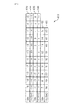
図3は、類似度に対する量子化テーブルの一例を示す図である。図3に示す量子化テーブル300において、上側の行310の各欄はインデックス値を表し、下側の行320の各欄は、同じ列のインデックス値に対応する類似度の量子化値を表す。また、類似度が取りうる値の範囲は-0.99〜+1である。例えば、周波数帯域kに対するインデックス値が3である場合、空間情報復号部14は、量子化テーブル300を参照することにより、類似度の量子化値を、そのインデックス値3に対応する0.60092とする。
FIG. 3 is a diagram illustrating an example of a quantization table for similarity. In the quantization table 300 shown in FIG. 3, each column in the
図4は、強度差に対する量子化テーブルの一例を示す図である。図4に示す量子化テーブル400において、行410、430及び450の各欄はインデックス値を表し、行420、440及び460の各欄は、それぞれ、同じ列の行410、430及び450の各欄に示されたインデックス値に対応する強度差の量子化値を表す。
例えば、周波数帯域kに対するインデックス値が5である場合、空間情報復号部14は、量子化テーブル400を参照することにより、強度差の量子化値を、そのインデックス値5に対応する10とする。
FIG. 4 is a diagram illustrating an example of a quantization table for the intensity difference. In the quantization table 400 shown in FIG. 4, each column of
For example, when the index value for the frequency band k is 5, the spatial
図5は、予測係数に対する量子化テーブルの一例を示す図である。図5に示す量子化テーブル500において、行510、520、530、540及び550の各欄はインデックス値を表す。また行515、525、535、545及び555の各欄は、それぞれ、同じ列の行510、520、530、540及び550の各欄に示されたインデックス値に対応する予測係数の量子化値を表す。
例えば、周波数帯域kに対するインデックス値が3である場合、空間情報復号部14は、量子化テーブル500を参照することにより、予測係数の量子化値を、そのインデックス値3に対応する0.3とする。
空間情報復号部14は、各周波数帯域の空間情報の量子化値をアップミックス部17へ出力する。
FIG. 5 is a diagram illustrating an example of a quantization table for prediction coefficients. In the quantization table 500 shown in FIG. 5, each column of the
For example, when the index value for the frequency band k is 3, the spatial
The spatial
残差信号復号部15は、符号化された、主信号と直交する成分である残差信号を復号する。MPEG Surround方式では、残差信号もAAC符号化されるので、その符号化の際に、残差信号に対してMDCTが実行される。したがって、残差信号復号部15は、例えば、ISO/IEC13818-7規格に記載されたAAC符号を復号する方法に従って残差信号を復号することにより、MDCT係数で表された残差信号が再生される。このMDCT係数は、直交変換部16へ出力される。
The residual
直交変換部16は、直交変換装置の一例であり、周波数領域の信号であるMDCT係数で表された残差信号を、時間周波数領域の信号であるQMF係数に変換する。なお、直交変換部16の詳細については後述する。
The
アップミックス部17は、周波数帯域ごとに、ステレオ信号の左側チャネル及び右側チャネルのQMF係数及び残差信号のQMF係数を、空間情報に基づいてアップミックスすることにより、5.1chのオーディオ信号の各チャネルのQMF係数を再生する。そのために、アップミックス部17は、例えば、ISO/IEC23003-1規格で規定されたアップミックスの手法を利用すればよい。例えば、アップミックス部17は、ステレオ信号の左側チャネルのQMF係数及び右側チャネルのQMF係数と、残差信号のQMF係数とを、空間情報を用いてアップミックスすることで、左側、右側、及び中央の3チャネルのQMF係数を算出する。さらに、アップミックス部17は、算出された左側チャネルのQMF係数を、左前方チャネルと左後方チャネルをダウンミックスする際に算出された空間情報を用いてアップミックスすることで、左前方チャネル及び左後方チャネルのQMF係数を算出する。同様に、アップミックス部17は、算出された右側チャネルのQMF係数を、右前方チャネルと右後方チャネルをダウンミックスする際に算出された空間情報を用いてアップミックスすることで、右前方チャネル及び右後方チャネルのQMF係数を算出する。さらに、アップミックス部17は、算出された中央チャネルのQMF係数を、中央チャネルと重低音チャネルをダウンミックスする際に算出された空間情報を用いてアップミックスすることで、中央チャネル及び重低音チャネルのQMF係数を算出する。
The
アップミックス部17は、再生した各チャネルのQMF係数を周波数時間変換部18へ出力する。
The
周波数時間変換部18は、逆直交ミラーフィルタ処理部の一例であり、各チャネルのQMF係数に対して、時間周波数変換部13により実行されるQMFフィルタバンク処理の逆変換処理を実行することにより、5.1chのオーディオ信号を再生する。そしてオーディオ復号装置1は、再生したオーディオ信号を、例えば、スピーカへ出力する。
The frequency
以下、直交変換部16について詳述する。
図6は、MDCT係数からQMF係数への変換の概念図である。MDCT係数601は、周波数軸方向にのみ複数の係数を有する。一方、QMF係数602は、時間軸方向と周波数軸方向の両方ともに複数の係数を持つ。
Hereinafter, the
FIG. 6 is a conceptual diagram of conversion from MDCT coefficients to QMF coefficients. The MDCT coefficient 601 has a plurality of coefficients only in the frequency axis direction. On the other hand, the
そこで、直交変換部16は、MDCT係数からQMF係数へ変換するために、ISO/IEC23003-1の規定に従って、周波数帯域603〜605のように、MDCT係数全体を隣接する周波数帯域同士が半分ずつオーバーラップする複数の周波数帯域で分割する。この場合、各周波数帯域は、通常のIMDCTが適用される周波数帯域の2倍の長さを持ち、例えば、連続する2N個のMDCT係数を含む。そして直交変換部16は、各周波数帯域に対してバタフライIMDET演算を行うことにより、周波数帯域間の折り返し歪みが相互に打ち消され、周波数帯域ごとに、時間軸方向に沿った2N個のQMF係数を得る。
しかし、このバタフライIMDET演算の演算量は非常に多い。そこで、本実施形態による直交変換部16は、このバタフライIMDET演算の演算量を削減するために、IMDET演算の基底関数の対称性を利用する。
Therefore, in order to convert the MDCT coefficient to the QMF coefficient, the
However, the amount of computation of this butterfly IMDET computation is very large. Therefore, the
図7は、直交変換部16の構成図である。直交変換部16は、窓処理部21と、逆修正離散指数変換部22と、係数調整部23とを有する。
FIG. 7 is a configuration diagram of the
窓処理部21は、残差信号のMDCT係数に、バタフライIMDCT及びバタフライIMDST用の窓関数及びゲイン(1/2N)1/2を乗じる。本実施形態では、窓関数wf[n]は、次式で表される。
逆修正離散指数変換部22は、周波数帯域全体を区切る複数の区間のそれぞれごとに、窓関数及びゲインが乗じられた残差信号のMDCT係数に対してIMDETを実行することにより、その区間に対応する周波数のQMF係数の実数成分及び虚数成分を算出する。
ここで、区間内に含まれるMDCT係数の数が8個、すなわち、N=4である場合、IMDETの演算は、次式のように、変換行列を用いて表される。
Here, when the number of MDCT coefficients included in the section is 8, that is, N = 4, the calculation of IMDET is expressed using a transformation matrix as in the following equation.
上記のように、IMDETに使用される基底関数は三角関数なので、基底関数には周期性がある。図8を参照しつつその周期性について説明する。図8に示したグラフ800は、k=0の場合のIMDCTの基底関数を表す。基底関数c0,k〜c7,kには、コサイン関数の1/2周期が含まれるので、基底関数の前半の区間、すなわち、c0,k〜c3,kに着目すると、c0,k〜c3,kは、その区間の中点に対して対称となっている。したがって、c0,k=c3,k及びc1,k=c2,kが成立する。同様に、後半の区間c4,k〜c7,kも、その区間の中点に対して、符号は反転するものの、基底関数の絶対値は対称となっている。したがって、c4,k=-c7,k及びc5,k=-c6,kが成立する。このような対称性は、kが0でない場合についても成立する。同様に、IMDSTの基底関数s0,k〜s7,kもサイン関数であり、(3)式から明らかなように、サイン関数の1/2周期が含まれるので、区間s0,k〜s3,k及び区間s4,k〜s7,kのそれぞれについて対称性がある。
したがって、(3)式の変換行列のうち、半分の行について計算結果が得られれば、他の行についてはその計算結果を利用できる。具体的には、逆修正離散指数変換部22は、(3)式によって計算されるQMF係数列の前半のうちの前半及び後半の何れかに対応する行と、そのQMF係数列の後半のうちの前半及び後半の何れかに対応する行についてのみ計算すればよい。例えば、y4(すなわち、n=3の行)とy3(すなわち、n=2の行)は、それぞれ、y1(すなわち、n=0の行)、y2(すなわち、n=1の行)についての計算結果を利用して算出できる。同様に、y8(すなわち、n=7の行)とy7(すなわち、n=6の行)は、それぞれ、y5(すなわち、n=4の行)、y6(すなわち、n=5の行)についての計算結果を利用して算出できる。
As described above, since the basis functions used for IMDET are trigonometric functions, the basis functions have periodicity. The periodicity will be described with reference to FIG. The
Therefore, if a calculation result is obtained for half of the transformation matrix of equation (3), the calculation result can be used for the other rows. Specifically, the inverse modified discrete
さらに、図9を参照しつつ、IMDCTの基底関数とIMDSTの基底関数の違いについて説明する。図9に示したグラフ900は、k=0の場合のIMDCTの基底関数を表す。一方、グラフ910は、k=0の場合のIMDSTの基底関数を表す。IMDCTの基底関数c0,k〜c7,kとIMDSTの基底関数s0,k〜s7,kの相違点は、コサイン関数かサイン関数かという点にすぎない。そのため、(3)式に示された変換行列の縦の列に着目すると、IMDCTの基底関数c0,k〜c7,kとIMDSTの基底関数s0,k〜s7,kとは、1/4周期ずれているだけで、基底関数の形状は同じである。したがって、IMDSTの基底関数s0,k〜s7,kの絶対値は、IMDCTの基底関数c0,k〜c7,kの何れかの絶対値と等しい。すなわち、逆修正離散指数変換部22は、(3)式において、IMDCT(すなわち、変換行列の上半分)またはIMDST(すなわち、変換行列の下半分)の何れか一方について計算すれば、他方はその計算結果を利用できる。例えば、逆修正離散指数変換部22は、(3)式によって計算されるQMF係数列の前半についてのIMDCTの計算結果を利用して、そのQMF係数列の後半のIMDSTを計算できる。逆に、逆修正離散指数変換部22は、(3)式によって計算されるQMF係数列の後半についてのIMDCTの計算結果を利用して、そのQMF係数列の前半のIMDSTを計算できる。同様に、逆修正離散指数変換部22は、るQMF係数列の前半及び後半についてのIMDSTの計算結果を利用して、そのQMF係数列の後半及び前半のIMDCTを計算できる。
Further, the difference between the IMDCT basis function and the IMDST basis function will be described with reference to FIG. The
したがって、結局、逆修正離散指数変換部22は、(3)式の行列に含まれる全ての要素のうちの1/4の要素についてのみ、MDCT係数との乗算を行うことで、IMDET演算全体を実行できる。
Therefore, in the end, the inverse modified discrete
そこで、逆修正離散指数変換部22は、上記のように、(3)式の行列の含まれる一部の要素についてのみ、MDCT係数との乗算を行うことでQMF係数を算出するために、記憶部31と、局所乗算部32と、係数算出部33とを有する。
Therefore, as described above, the inverse modified discrete
記憶部31は、例えば、不揮発性の読み出し専用のメモリ回路と揮発性の読み書き可能なメモリ回路とを有する。そして記憶部31は、IMDET演算が行われる区間の長さごとに、MDCT係数に乗じる基底関数の要素を表すテーブルを記憶する。各テーブルには、例えば、算出されるQMF係数を含む区間の前半のうちの前半及び後半の何れかを算出するための基底関数の値と、その区間の後半のうちの前半及び後半の何れかを算出するための基底関数の値が格納される。この基底関数の値は、QMF係数の実数成分を算出するために用いられる値、すなわち、IMDCT用の基底関数の値であってもよく、あるいは、QMF係数の虚数成分を算出するために用いられる値、すなわち、IMDST用の基底関数の値であってもよい。t例えば、(3)式に示されるように、IMDET演算が行われる区間の長さが8、すなわち、N=4に対応するテーブルは、(3)式に示された行列のうちの1,2,5,6行目の基底関数の要素{c0,k, c1,k, c4,k, c5,k}を格納する。また、IMDET演算が行われる区間の長さが4、すなわち、N=2の場合、基底関数の行列は、8行×4列の要素を持つ。そのうち、上側の4行の要素がIMDCTの基底関数cn,k(n=0,..,3, k=0,..,3)であり、下側の4行の要素がIMDSTの基底関数sn,k(n=0,..,3, k=0,..,3)である。このうち、N=2に対応するテーブルは、1行目及び3行目の基底関数の要素{c0,k, c2,k}を格納する。
The
記憶部31は、さらに、局所乗算部32による中間演算値を、係数算出部33が利用できるように一時的に記憶する。
The
局所乗算部32は、残差信号のフレームの長さに応じて、記憶部31に記憶されているテーブルの中から、利用するテーブルを読み込む。そして局所乗算部32は、テーブルに格納された各基底関数の要素に対応するMDCT係数を乗じる。そして局所乗算部32は、乗算を行った変換行列の行ごとに、奇数列の要素とMDCT係数の積の総和Σci,2k*x[2k+1] (k=0, 1,..,2N-1)と、偶数列の要素とMDCT係数の積の総和Σci,2k+1*x[2(k+1)]をそれぞれ算出する。そして局所乗算部32は、それら総和を中間演算値として記憶部31に記憶する。
The
図10は、区間の長さが8(N=4)の場合における、局所乗算部32の処理の説明図である。変換行列とMDCT係数列の積である行列1000のうち、1,2,5,6行目のそれぞれについて、局所乗算部32は、実線で囲まれた奇数列の要素ci,2k*x[2k+1]を計算する。そして局所乗算部32は、その要素の総和Σci,2k*x[2k+1]をyioddとして算出する。また局所乗算部32は、点線で囲まれた偶数列の要素ci,2k+1*x[2(k+1)]を計算する。そして局所乗算部32は、その要素の総和Σci,2k+1*x[2(k+1)]をyievenとして算出する。
FIG. 10 is an explanatory diagram of the processing of the
係数算出部33は、記憶部31に記憶されている中間演算値を利用して、バタフライ演算を行うことにより、QMF係数の実数成分及び虚数成分を算出する。
図11は、係数算出部33により実行されるバタフライ演算の説明図である。この例では、QMF係数列を、各QMF係数を算出するために利用される基底関数の値が対称となるように4分割した複数のサブ区間のうち、1番目と3番目のサブ区間について局所乗算部32による中間演算値が得られている。すなわち、IMDETの変換行列とMDCT係数の積である行列1100を縦方向に等分割した8個のブロックのうち、1番目のブロック1101と3番目のブロック1103の各行について、奇数列の要素の総和yioddと偶数列の要素の総和yievenが算出されている。
なお、各ブロックの右端に示した番号は、N=4の場合において、その行の計算に利用される、局所乗算部32により中間演算値が計算された行の番号を表す。
The
FIG. 11 is an explanatory diagram of the butterfly calculation executed by the
Note that the number shown at the right end of each block represents the number of the row in which the intermediate operation value is calculated by the
ブロック1101とブロック1103の各行については、係数算出部33は、単純に奇数列の要素の総和yioddと偶数列の要素の総和yievenを加算することで、対応するQMF係数の実数成分を算出できる。
For each row in the
一方、2番目のブロック1102の各行に相当するQMF係数の値は、1番目のブロック1101の各行に相当するQMF係数の値と上下対称になっている。例えば、N=4の場合、各ブロックには、2行ずつ含まれる。そのため、ブロック1102の上側の行、すなわち行列1100の3番目の行に相当するQMF係数の実数成分y3は、ブロック1101の下側の行、すなわち、行列1100の2番目の行に相当するQMF係数の実数成分y2と等しい。同様に、ブロック1102の下側の行、すなわち行列1100の4番目の行に相当するQMF係数の実数成分y4は、ブロック1101の上側の行、すなわち、行列1100の1番目の行に相当するQMF係数の実数成分y1と等しい。したがって、係数算出部33は、ブロック1102内の各行に相当するQMF係数の実数成分に、ブロック1101内の対応する行のQMF係数の実数成分を代入する。例えば、N-4の場合、y3=y2、かつy4=y1となる。
On the other hand, the value of the QMF coefficient corresponding to each row of the
また、4番目のブロック1104の各行に相当するQMF係数の値は、3番目のブロック1103の各行に相当するQMF係数の値と上下対称、かつ、符号が反転されている。したがって、係数算出部33は、ブロック1104内の各行に相当するQMF係数の実数成分に、ブロック1103内の対応する行のQMF係数の実数成分の符号を反転した上で代入する例えば、N=4の場合、y8=-y5、かつ、y7=-y6となる。
Further, the QMF coefficient value corresponding to each row of the
さらに、IMDCTの基底関数と、IMDSTの基底関数とでは、位相が1/4周期ずれているだけなので、係数算出部33は、8番目のブロック1108内の各行の値を、1番目のブロック1101内の各行の中間演算値を利用して算出できる。N=4の場合、8番目のブロック1108の下側の行、すなわち、行列1100の16番目の行に相当するQMF係数の虚数成分y16は、ブロック1101の上側の行y1の偶数列の要素の総和y1evenから奇数列の要素の総和y1oddを減じた値(y1even-y1odd)となる。同様に、行列1100の15番目の行に相当するQMF係数の虚数成分y15は、ブロック1101の下側の行y2の偶数列の要素の総和y2evenから奇数列の要素の総和y2oddを減じた値(y2even-y2odd)となる。また同様に、係数算出部33は、6番目のブロック1106内の各行に対応するQMF係数の虚数成分を、3番目のブロック1103の各行の中間演算値を利用して算出できる。具体的には、行列1100の12番目の行に相当するQMF係数の虚数成分y12は、ブロック1103の上側の行y5の偶数列の要素の総和y5evenから奇数列の要素の総和y5oddを減じた値(y5even-y5odd)となる。同様に、行列1100の11番目の行に相当するQMF係数の虚数成分y11は、ブロック1103の下側の行y6の偶数列の要素の総和y6evenから奇数列の要素の総和y6oddを減じた値(y6even-y6odd)となる。
Furthermore, since the phase of the IMDCT basis function and the IMDST basis function are only shifted by a quarter period, the
また、7番目のブロック1107の各行に相当するQMF係数の値は、8番目のブロック1108の各行に相当するQMF係数の値と上下対称になっている。例えば、N=4の場合、ブロック1107の上側の行、すなわち行列1100の13番目の行に相当するQMF係数の虚数成分y13は、ブロック1108の下側の行、すなわち、行列1100の16番目の行に相当するQMF係数の虚数成分y16と等しい。同様に、ブロック1107の下側の行、すなわち、行列1100の14番目の行に相当するQMF係数の虚数成分y14は、行列1100の15番目の行に相当するQMF係数の虚数成分y15と等しい。
The QMF coefficient value corresponding to each row of the
また、5番目のブロック1105の各行に相当するQMF係数の値は、6番目のブロック1106の各行に相当するQMF係数の値と上下対称、かつ、符号が反転されている。したがって、係数算出部33は、ブロック1105内の各行に相当するQMF係数の虚数成分に、ブロック1106内の対応する行のQMF係数の虚数成分の符号を反転した上で代入する例えば、N=4の場合、y9=-y12、かつ、y10=-y11となる。
The QMF coefficient value corresponding to each row of the
図12は、変形例として、IMDETの変換行列とMDCT係数の積である行列1200を縦方向に等分割した8個のブロックのうち、5番目のブロックと7番目のブロックについて局所乗算部32により中間演算値が算出されたときのバタフライ演算の説明図である。
この場合には、5番目のブロック1205と7番目のブロック1207は、それぞれ、IMDSTに相当するので、基底関数はサイン関数となる。したがって、N=4の場合、変換行列とMDCT係数列の積である行列のうち、9,10,13,14行目のそれぞれについて、奇数列の要素の総和Σsi,2k*x[2k+1]がyioddとして、局所乗算部32により算出される。同様に、偶数列の要素の総和Σsi,2k+1*x[2(k+1)]がyievenとして、局所乗算部32により算出される。そしてブロック1205とブロック1207の各行については、係数算出部33は、単純に奇数列の要素の総和yioddと偶数列の要素の総和yievenを加算することで、対応するQMF係数の虚数成分yi(i=9,10,13,14)を算出できる。
FIG. 12 shows, as a modification, the
In this case, since the
一方、8番目のブロック1208の各行に相当するQMF係数の値は、7番目のブロック1207の各行に相当するQMF係数の値と上下対称になっている。したがって、例えば、N=4の場合、係数算出部33は、ブロック1208内の各行に相当するQMF係数の虚数成分y15、y16について、それぞれ、y15=y14、y16=y13とする。
On the other hand, the value of the QMF coefficient corresponding to each row of the
また、6番目のブロック1206の各行に相当するQMF係数の値は、5番目のブロック1205の各行に相当するQMF係数の値と上下対称、かつ、符号が反転されている。したがって、例えば、N=4の場合、係数算出部33は、ブロック1206内の各行に相当するQMF係数の虚数成分y11、y12について、それぞれ、y11=-y10、y12=-y9とする。
The QMF coefficient value corresponding to each row of the
さらに、IMDCTの基底関数と、IMDSTの基底関数とでは、位相が1/4周期ずれているだけなので、係数算出部33は、2番目のブロック1202内の各行の値を、7番目のブロック1207内の各行の中間演算値を利用して算出できる。N=4の場合、2番目のブロック1202の下側の行、すなわち、行列1200の4番目の行に相当するQMF係数の実数成分y4は、ブロック1207の上側の行y13の奇数列の要素の総和y13oddから偶数列の要素の総和y13evenを減じた値(y13odd-y13even)となる。同様に、行列1200の3番目の行に相当するQMF係数の実数成分y3は、ブロック1207の下側の行y14の奇数列の要素の総和y14oddから偶数列の要素の総和y14evenを減じた値(y14odd-y14even)となる。また同様に、係数算出部33は、4番目のブロック1204内の各行に対応するQMF係数の実数成分を、5番目のブロック1205の各行の中間演算値を利用して算出できる。具体的には、行列1200の7番目の行に相当するQMF係数の実数成分y7は、ブロック1205の下側の行y10の奇数列の要素の総和y10oddから偶数列の要素の総和y10evenを減じた値(y10odd-y10even)となる。同様に、行列1200の8番目の行に相当するQMF係数の実数成分y8は、ブロック1205の上側の行y9の奇数列の要素の総和y9oddから偶数列の要素の総和y9evenを減じた値(y9odd-y9even)となる。
Furthermore, since the phase of the IMDCT basis function and the IMDST basis function are only shifted by a quarter period, the
また、1番目のブロック1201の各行に相当するQMF係数の値は、2番目のブロック1202の各行に相当するQMF係数の値と上下対称になっている。したがって、例えば、N=4の場合、係数算出部33は、ブロック1201内の各行に相当するQMF係数の実数成分y1、y2について、それぞれ、y1=y4、y2=y3とする。
The QMF coefficient value corresponding to each row of the
また、3番目のブロック1203の各行に相当するQMF係数の値は、4番目のブロック1204の各行に相当するQMF係数の値と上下対称、かつ、符号が反転されている。したがって、例えば、N=4の場合、係数算出部33は、ブロック1203内の各行に相当するQMF係数の実数成分y5、y6について、それぞれ、y5=-y8、y6=-y7とする。
Also, the QMF coefficient value corresponding to each row of the
上記のように、QMF係数列の前半区間の実数成分と後半区間の虚数成分を算出するためには、それら区間のうち、何れか一方のさらに前半または後半について、基底関数と対応するMDF係数の積が計算されればよい。同様に、QMF係数列の後半区間の実数成分と前半区間の虚数成分を算出するためには、それら区間のうち、何れか一方のさらに前半または後半について、基底関数と対応するMDF係数の積が計算されればよい。 As described above, in order to calculate the real component and the imaginary component of the second half of the QMF coefficient sequence, the MDF coefficient corresponding to the basis function is calculated for either the first half or the second half of those sections. The product need only be calculated. Similarly, in order to calculate the real component of the second half section and the imaginary component of the first half section of the QMF coefficient sequence, the product of the MDF coefficient corresponding to the basis function is calculated for either the first half or the second half of those sections. It only has to be calculated.
係数算出部33は、QMF係数の実数成分及び虚数成分を係数調整部23へ出力する。
The
係数調整部23は、逆修正離散指数変換部22から出力された、残差信号のQMF係数のそれぞれの実数成分と虚数成分とを合成することで、残差信号の各QMF係数を得る。具体的には、係数調整部23は、次式に従って、QMF係数を算出する。
図13は、直交変換部16により実行される直交変換処理の動作フローチャートである。なお、直交変換部16は、個々の周波数帯域に相当する適用区間ごとに、以下の動作フローに従って直交変換処理を実行する。
FIG. 13 is an operation flowchart of orthogonal transform processing executed by the
直交変換部16の窓処理部21は、残差信号のMDCT係数に対して窓関数及びゲインを乗じる(ステップS101)。そして窓処理部21は、窓関数及びゲインが乗じられたMDCT係数を直交変換部16の逆修正離散指数変換部22の局所乗算部32へ出力する。
The
局所乗算部32は、適用区間の長さに応じて、QMF係数を算出するための基底関数の値が対称となるようにQMF係数列を分割したサブ区間のうちの着目するサブ区間に含まれる基底関数値を格納するテーブルを記憶部31から読み込む(ステップS102)。そして局所乗算部32は、着目するサブ区間に含まれるQMF係数の実数成分に対応する奇数列の基底関数と対応するMDCT係数の積の総和と、偶数列の基底関数と対応するMDCT係数の積の総和とをそれぞれ算出する。そして局所乗算部32は、その計算結果を中間演算値として記憶部31に記憶する(ステップS103)。
The
係数算出部33は、着目するサブ区間について、奇数列の基底関数と対応するMDCT係数の積の総和と、偶数列の基底関数と対応するMDCT係数の積の総和との和を、そのサブ区間に含まれるQMF係数の実数成分として算出する(ステップS104)。さらに、係数算出部33は、着目するサブ区間以外のサブ区間について、記憶部31に記憶されている中間演算値を用いて、基底関数の対称性を利用したバタフライ演算により、QMF係数の実数成分を算出する(ステップS105)。また係数算出部33は、着目するサブ区間の中間演算値から、IDMCTの基底関数とIDMSTの基底関数の周期のずれを補償するとともにサブ区間同士の基底関数の対称性を利用して各サブ区間のQMF係数の虚数成分を算出する(ステップS106)。
The
直交変換部16の係数調整部23は、QMF係数の実数成分と虚数成分を合成することでQMF係数を得る(ステップS107)。そして直交変換部16は、直交変換処理を終了する。なお、局所乗算部32は、ステップS103にて、着目するサブ区間に含まれるQMF係数の虚数成分に対応する奇数列の基底関数と対応するMDCT係数の積の総和と、偶数列の基底関数と対応するMDCT係数の積の総和とを、中間演算値として算出してもよい。この場合、係数算出部33は、ステップS104及びS105では、各サブ区間に含まれるQMF係数の虚数成分を算出し、ステップS106では、各サブ区間に含まれるQMF係数の実数成分を算出する。
The
図14は、オーディオ復号装置1により実行されるオーディオ復号処理の動作フローチャートである。オーディオ復号装置1は、フレームごとに、下記の動作フローチャートに従ってオーディオ信号を再生する。
FIG. 14 is an operation flowchart of audio decoding processing executed by the
分離部11は、符号化データストリームからAAC符号、SBR符号といった主信号符号、空間情報符号及び残差信号符号を取り出す(ステップS201)。
主信号復号部12は、分離部11から受け取った主信号符号を復号することにより、ステレオ信号を再生する(ステップS202)。時間周波数変換部13は、得られたステレオ信号に対してQMFフィルタバンクを適用することにより、時間周波数領域のQMF係数に変換する(ステップS203)。
The
The main
一方、空間情報復号部14は、分離部11から受け取った空間情報符号を復号することにより空間情報を再生する(ステップS204)。そして空間情報復号部14は、得られた空間情報をアップミックス部17へ出力する。
On the other hand, the spatial
また、残差信号復号部15は、分離部11から受け取った残差信号符号を復号することにより、残差信号のMDCT係数を再生する(ステップS205)。そして直交変換部16は、残差信号のMDCT係数に対して、基底関数の対称性に基づいて一部のQMF係数の中間演算値を他のQMF係数の算出に利用することによってバタフライIMDETを実行することにより、残差信号のQMF係数を算出する(ステップS206)。
Further, the residual
アップミックス部17は、ステレオ信号のQMF係数及び残差信号のQMF係数を空間情報を用いてアップミックスすることにより、元のオーディオ信号の各チャネルのQMF係数を再生する(ステップS207)。
周波数時間変換部18は、各チャネルのQMF係数を周波数時間変換して各チャネルのオーディオ信号を再生する(ステップS208)。
そしてオーディオ復号装置は、オーディオ復号処理を終了する。
The
The frequency
Then, the audio decoding device ends the audio decoding process.
以上に説明してきたように、本実施形態による直交変換装置は、MDCT係数をQMF係数に変換するためのバタフライIMDETの演算量を、基底関数の対称性を利用することで、1/4に削減できる。そのため、この直交変換装置を含むオーディオ復号装置は、残差信号のMDCT係数をQMF係数に変換するための演算量を削減できる。 As described above, the orthogonal transform apparatus according to the present embodiment reduces the amount of computation of the butterfly IMDET for converting the MDCT coefficient to the QMF coefficient to 1/4 by using the symmetry of the basis function. it can. Therefore, the audio decoding device including this orthogonal transformation device can reduce the amount of calculation for converting the MDCT coefficient of the residual signal into the QMF coefficient.
次に、直交変換装置の第2の実施形態について説明する。 Next, a second embodiment of the orthogonal transform device will be described.
IMDETを何の高速化手法も利用せずに実行する場合、IMDETの演算量は、適用区間に含まれるMDCT係数の数の2乗のオーダーとなる。そのため、上記の実施形態でも、IMDETの演算量は1/4となるものの、演算量のオーダー自体は、適用区間に含まれるMDCT係数の数の2乗のオーダーとなる。 When IMDET is executed without using any speed-up method, the IMDET calculation amount is in the order of the square of the number of MDCT coefficients included in the applicable section. Therefore, even in the above embodiment, the IMDET calculation amount is 1/4, but the calculation amount order itself is the order of the square of the number of MDCT coefficients included in the applicable section.
一方、高速フーリエ変換(Fast Fourier Transform, FFT)を利用してIMDCT及びIMDSTを実行する方法が知られている。そのような方法は、例えば、Rolf Gluth、「REGULAR FFT-RELATED TRANSFORM KERNELS FOR DCT/DST-BASED POLYPHASE FILTER BANKS」、IEEE Acoustics, Speech, and Signal Processing, ICASSP-91、1991年、vol.3、p.2205-2208に開示されている。この文献に記載された方法では、入力される信号列に対して複素平面内での回転といった事前処理及び事後処理とともにFFTを実行することで、IMDCT及びIMDSTが実現できる。FFTの演算量は、入力される信号点の数Nが2のべき乗である場合、NlogNのオーダーとなる。したがって、IMDETの適用区間に含まれるMDCT係数の数が2のべき乗であり、かつ、そのMDCT係数の数が多いほど、FFTを利用してIMDETを実行することで演算量が削減される。 On the other hand, a method for executing IMDCT and IMDST using Fast Fourier Transform (FFT) is known. Such a method is described in, for example, Rolf Gluth, `` REGULAR FFT-RELATED TRANSFORM KERNELS FOR DCT / DST-BASED POLYPHASE FILTER BANKS '', IEEE Acoustics, Speech, and Signal Processing, ICASSP-91, 1991, vol. 3, p. .2205-2208. In the method described in this document, IMDCT and IMDST can be realized by executing FFT on the input signal sequence together with pre-processing and post-processing such as rotation in a complex plane. The amount of FFT calculation is on the order of NlogN when the number N of input signal points is a power of 2. Therefore, as the number of MDCT coefficients included in the IMDET application section is a power of 2, and the number of MDCT coefficients is larger, the amount of calculation is reduced by executing IMDET using FFT.
そこで、第2の実施形態による直交変換装置は、IMDET演算の適用区間の長さに応じて、IMDET演算を実行する方法を、上記の実施形態による方法か、FFTを利用した方法かで切り替える。 Therefore, the orthogonal transformation device according to the second embodiment switches the method for executing the IMDET calculation between the method according to the above-described embodiment and the method using FFT according to the length of the application interval of the IMDET calculation.
図15は、第2の実施形態による直交変換装置16’の構成図である。直交変換装置16’は、窓処理部21と、切り替え部24と、逆修正離散指数変換部22と、第2逆修正離散指数変換部25と、係数調整部23とを有する。図15に示された直交変換装置16’の各構成要素には、図7に示された第1の実施形態による直交変換装置16の対応する構成要素の参照番号と同じ参照番号を付した。第2の実施形態による直交変換装置16’は、第1の実施形態による直交変換装置16と比較して、切り替え部24及び第2逆修正離散指数変換部25を有する点で異なる。そこで以下では、切り替え部24及び第2逆修正離散指数変換部25について説明する。
FIG. 15 is a configuration diagram of an
切り替え部24は、IMDETの適用区間の長さに応じて、基底関数の対称性を利用する逆修正離散指数変換部22及びFFTを利用する第2逆修正離散指数変換部25のうちの何れかを選択する。
The switching
図16は、切り替え部24による切り替え処理の動作フローチャートである。
切り替え部24は、IMDETの適用区間に含まれるMDCT係数の数Mが8以上か否か判定する(ステップS301)。MDCT係数の数Mが8以上である場合(ステップS301−Yes)、切り替え部24は、MDCT係数の数Mが2のべき乗であるか否か判定する(ステップS302)。MDCT係数の数Mが2のべき乗である場合(ステップS302−Yes)、切り替え部24は、FFTを利用する第2逆修正離散指数変換部25にMDCT係数を入力する(ステップS303)。
FIG. 16 is an operation flowchart of switching processing by the switching
The switching
一方、MDCT係数の数Mが2のべき乗でないか(ステップS302−No)、その数Mが8未満である場合(ステップS301−No)、切り替え部24は、基底関数の対称性を利用する逆修正離散指数変換部22にMDCT係数を入力する(ステップS304)。ステップS303またはS304の後、切り替え部24は、切り替え処理を終了する。
On the other hand, if the number M of the MDCT coefficients is not a power of 2 (step S302-No), or if the number M is less than 8 (step S301-No), the switching
第2逆修正離散指数変換部25は、FFTを利用して、入力されたMDCT係数に対してIMDETを実行する。
図17は、第2逆修正離散指数変換部25の構成図である。第2逆修正離散指数変換部25は、入れ替え部41と、反転部42と、バタフライ逆コサイン変換部43と、バタフライ逆サイン変換部44とを有する。本実施形態では、バタフライ逆コサイン変換部43及びバタフライ逆サイン変換部44は、演算量を削減するために、FFTを利用してIMDCT演算及びIMDST演算を実行する方法を採用する。
The second inversely modified discrete
FIG. 17 is a configuration diagram of the second inverse modified discrete
バタフライIMDCT演算及びバタフライIMDST演算と、通常のIMDCT演算及び通常のIMDST演算には、以下に説明するような相違点が存在する。
一般に、バタフライIMDCT演算は、次式で表される。
そこで第2逆修正離散指数変換部25は、IMDCT及びIMDSTを実行する前に、適用区間内のMDCT係数の数及び基底関数の位相を、通常のIMDCT演算またはIMDST演算における係数の数及び基底関数の位相と一致させるよう、MDCT係数を並び替え、符号を反転する。
The butterfly IMDCT operation and the butterfly IMDST operation are different from the normal IMDCT operation and the normal IMDST operation as described below.
In general, the butterfly IMDCT operation is expressed by the following equation.
Therefore, before executing IMDCT and IMDST, the second inverse modified discrete
図18を参照しつつ、バタフライIMDCTの基底コサイン関数と通常のIMDCTの基底コサイン関数の関係について説明する。図18において、横軸は、MDCT係数の周波数kを表す。そしてグラフ1801は、通常のIMDCTの基底コサイン関数c1[k]を表し、グラフ1802は、バタフライIMDCTの基底コサイン関数c2[k]を表す。関数c1[k]、c2[k]は、それぞれ、(5)式及び(6)式における、三角関数の部分に相当するので次式で表される。
図18及び(7)式、(8)式から明らかなように、関数c1[k]と関数c2[k]とでは、kの値がNに相当する分だけ位相がずれている。すなわち、区間[0,N-1]における、バタフライIMDCTの基底コサイン関数c2[k]の値は、区間[N,2N-1]における、通常のバタフライIMDCTの基底コサイン関数c1[k]の値と等しい。 As is clear from FIGS. 18 and (7) and (8), the function c1 [k] and the function c2 [k] are out of phase by a value corresponding to N of k. That is, the value of the base cosine function c2 [k] of the butterfly IMDCT in the interval [0, N-1] is the value of the base cosine function c1 [k] of the normal butterfly IMDCT in the interval [N, 2N-1]. Is equal to
また、基底コサイン関数c1[k]、c2[k]とも、kの値が2Nだけ異なるときのその関数の値c1[k-2N]、c2[k-2N]と比較して、絶対値が等しく、かつ、符号が反転する。すなわち、基底コサイン関数c1[k]とc2[k]の間には、以下の関係が成立する。
したがって、以下の式が成立する。
また、バタフライIMDST演算の基底サイン関数と、通常のIMDST演算の基底サイン関数についても同様の関係が成立する。したがって、バタフライIMDST演算についても、適用区間内の前半のMDCT係数と後半のMDCT係数の順序を入れ替え、入れ替え後の前半のMDCT係数の符号を反転することで、前半部分と後半部分のそれぞれに対して、通常のIMDST演算が適用可能となる。 The same relationship holds for the basis sine function of the butterfly IMDST operation and the basis sine function of the normal IMDST operation. Therefore, for the butterfly IMDST calculation, the order of the first and second half MDCT coefficients in the applicable interval is changed, and the sign of the first and second half MDCT coefficients is reversed. Thus, a normal IMDST calculation can be applied.
そこで、入れ替え部41は、適用区間内の前半のMDCT係数と後半のMDCT係数を入れ替える。図19を参照しつつ、入れ替え部41の処理を説明する。入れ替え部41は、窓関数及びゲインが乗算されたMDCT係数x[k]を、図19の矢印で示されるように前半と後半の順序を入れ替えることで、入れ替え後のMDCT係数x'[k]を求める。この入れ替えの処理は、次式で表される。
入れ替え部41は、入れ替え後のMDCT係数x'[k]の前半部分、すなわち、元のMDCT係数の後半部分をバタフライ逆コサイン変換部43の逆コサイン変換部51−1と、バタフライ逆サイン変換部44の逆サイン変換部53−1へ出力する。一方、入れ替え部41は、入れ替え後のMDCT係数x'[k]の後半部分、すなわち、元のMDCT係数の前半部分を反転部42へ出力する。
The
反転部42は、入れ替え後のMDCT係数x'[k]の後半部分の符号を反転する。そして反転部42は、符号反転後のMDCT係数x'[k]をバタフライ逆コサイン変換部43の逆コサイン変換部51−2と、バタフライ逆サイン変換部44の逆サイン変換部53−2へ出力する。
The
バタフライ逆コサイン変換部43は、バタフライIMDCT演算をそのまま実行する代わりに、適用区間内のMDCT係数の順序の入れ替え等を行った上で、FFTを利用した通常のIMDCT演算を実行することで、QMF係数の実数成分を算出する。再度図17を参照すると、バタフライ逆コサイン変換部43は、逆コサイン変換部51−1、51−2と、加算部52とを有する。
同様に、バタフライ逆サイン変換部44は、適用区間内のMDCT係数の順序の入れ替え等を行った上で、FFTを利用した通常のIMDST演算を実行することで、QMF係数の虚数成分を算出する。そのために、バタフライ逆サイン変換部44は、逆サイン変換部53−1、53−2と、加算部54とを有する。
なお、以下では、バタフライ逆コサイン変換部43についてのみ説明する。バタフライ逆サイン変換部44は、変換に用いられる基底関数をコサイン関数からサイン関数に変更するだけで、バタフライ逆コサイン変換部43と同様に、MDCT係数に対してFFTを利用したIMDST演算を行うことでバタフライIMDST演算を実行できる。
The butterfly inverse
Similarly, the butterfly inverse
Only the butterfly inverse
逆コサイン変換部51−1は、(10)式の右辺の第1項に対するIMDCT演算を、FFTを利用して実行する。一方、逆コサイン変換部51−2は、(10)式の右辺の第2項に対するIMDCT演算を、FFTを利用して実行する。逆コサイン変換部51−1、51−2は、例えば、上述した、Rolf Gluth、「REGULAR FFT-RELATED TRANSFORM KERNELS FOR DCT/DST-BASED POLYPHASE FILTER BANKS」、IEEE Acoustics, Speech, and Signal Processing, ICASSP-91、1991年、vol.3、p.2205-2208に開示された手法を利用する。なお、逆コサイン変換部51−1と51−2は、扱うデータ以外は同一なので、以下では、逆コサイン変換部51−1について説明する。 The inverse cosine transform unit 51-1 performs an IMDCT operation on the first term on the right side of the equation (10) using FFT. On the other hand, the inverse cosine transform unit 51-2 performs an IMDCT operation on the second term on the right side of the equation (10) using FFT. The inverse cosine transform units 51-1 and 51-2 are, for example, the above-mentioned Rolf Gluth, “REGULAR FFT-RELATED TRANSFORM KERNELS FOR DCT / DST-BASED POLYPHASE FILTER BANKS”, IEEE Acoustics, Speech, and Signal Processing, ICASSP- 91, 1991, vol.3, p.2205-2208. Since the inverse cosine transform units 51-1 and 51-2 are the same except for data to be handled, the inverse cosine transform unit 51-1 will be described below.
図20は、逆コサイン変換部51−1の構成図である。逆コサイン変換部51−1は、上記の文献に開示された手法に従って、事前回転部61と、高速フーリエ変換部62と、事後回転部63とを有する。
FIG. 20 is a configuration diagram of the inverse cosine transform unit 51-1. The inverse cosine transform unit 51-1 includes a
事前回転部61は、基底の三角関数の対称性を利用して計算範囲を狭くするために、次式に従って入力されたMDCT係数x'[k]を1/4ずつ合成することにより、合成関数f[k]を得る。
高速フーリエ変換部62は、合成関数f'[k]に対して、FFTを実行する。なお、高速フーリエ変換部62は、FFTとして知られている様々な演算方法を適用できる。そして高速フーリエ変換部62は、FFTを行うことによって得られた係数F[n]を事後回転部63へ出力する。
The fast
事後回転部63は、次式に従って、係数F[n]を、事前回転部61による回転方向とは逆向きに1/8回転させることで係数F'[n]を算出する。
事後回転部63は、次式に従って、複素平面上の係数F'[n]を実数平面上の係数F''[n]に変換する。
加算部52は、逆コサイン変換部51−1から出力された係数に、逆コサイン変換部51−2から出力された係数を加算する。これにより、(10)式の右辺の計算が完了するので、MDCT係数に対するバタフライIMDCTが完了し、QMF係数の実数成分が得られる。加算部52は、得られたQMF係数の実数成分を係数調整部23へ出力する。
The adding
バタフライ逆サイン変換部44も、バタフライ逆コサイン変換部43と同様にFFTを利用してIMDSTを実行することで、QMF係数の虚数成分を算出する。そしてバタフライ逆サイン変換部44は、得られたQMF係数の虚数成分を係数調整部23へ出力する。
係数調整部23は、第2逆修正離散指数変換部25からQMF係数の実数成分と虚数成分を受け取った場合も、(4)式に従ってその実数成分と虚数成分を合成することで、QMF係数を算出できる。
Similarly to the butterfly inverse
Even when the
以下のテーブルは、本実施形態による、一つの適用区間に含まれるMDCT係数の数M(=2N)に対する、IMDET1回あたりの演算量を示すテーブルである。
図21は、適用区間に含まれるMDCT係数の数Mに対する、基底関数の対称性を利用するIMDETの演算量とFFTを利用するIMDETの演算量の関係を表すグラフである。グラフ2100は、MDCT係数の数Mと基底関数の対称性を利用したIMDETの乗算回数の関係を表し、グラフ2110は、MDCT係数の数MとFFTを利用したIMDETの乗算回数の関係を表す。図21から明らかなように、Mが8よりも小さい場合には、基底関数の対称性を利用してIMDETを実行する方が、FFTを利用してIMDETを実行するよりも演算量が少なくて済む。これは、FFTを利用する手法では、事前処理と事後処理の演算量の負荷が相対的に大きくなるためである。そのため、本実施形態では、切り替え部24により、Mが8未満のときまたはMが2のべき乗でないときには基底関数の対称性を利用してIMDETを実行するように、逆修正離散指数変換部22が選択される。特に、残差信号に適用されるAAC符号化方式などでは、アタック音に対して短いフレームが適用されるので、IMDETの適用区間に含まれるMDCT係数の数が8未満となることがある。そのため、本実施形態による直交変換装置及びその直交変換装置を利用するオーディオ復号装置は、残差信号に短いフレームが適用されたときなお、FFTを利用してIMDETを実行するよりも演算量を削減できる。一方、この直交変換装置及びオーディオ復号装置は、比較的長いフレームで残差信号がAAC符号化されているような場合には、FFTを利用してIMDETを実行することで、IMDETの演算量を削減できる。
FIG. 21 is a graph showing the relationship between the IMDET calculation amount using the basis function symmetry and the IMDET calculation amount using the FFT with respect to the number M of MDCT coefficients included in the application interval. A
なお、変形例によれば、局所乗算部32は、中間演算値として、QMF係数列の着目するサブ区間に含まれるQMF係数の実数成分または虚数成分に対応する、各基底関数値と対応意するMDF係数の積のみを算出してもよい。この場合には、係数算出部33が、各QMF係数について、奇数列の基底関数値とMDF係数の積の総和と、偶数列の基底関数値とMDF係数の積の総和を算出すればよい。この変形例でも、基底関数値とMDF係数の積の演算回数を通常のIMDETにおける基底関数値とMDF係数の積の演算回数の1/4にできるので、IMDET全体の演算量を削減できる。
Note that, according to the modification, the
上記の実施形態または変形例による直交変換装置が有する各部の機能をコンピュータに実現させるコンピュータプログラムは、半導体メモリ、磁気記録媒体または光記録媒体などの記録媒体に記憶された形で提供されてもよい。同様に、上記の実施形態または変形例によるオーディオ復号装置が有する各部の機能をコンピュータに実現させるコンピュータプログラムは、半導体メモリ、磁気記録媒体または光記録媒体などの記録媒体に記憶された形で提供されてもよい。ただし、そのような記録媒体には、搬送波は含まれない。 A computer program that causes a computer to realize the functions of the units included in the orthogonal transform apparatus according to the above-described embodiment or modification may be provided in a form stored in a recording medium such as a semiconductor memory, a magnetic recording medium, or an optical recording medium. . Similarly, a computer program that causes a computer to realize the functions of the units included in the audio decoding device according to the above-described embodiment or modification is provided in a form stored in a recording medium such as a semiconductor memory, a magnetic recording medium, or an optical recording medium. May be. However, such a recording medium does not include a carrier wave.
図22は、上記の実施形態またはその変形例によるオーディオ復号装置の各部の機能を実現するコンピュータプログラムが動作することにより、オーディオ復号装置として動作するコンピュータの構成図である。 FIG. 22 is a configuration diagram of a computer that operates as an audio decoding device by operating a computer program that realizes the functions of the respective units of the audio decoding device according to the above-described embodiment or its modification.
コンピュータ100は、ユーザインターフェース部101と、通信インターフェース部102と、記憶部103と、記憶媒体アクセス装置104と、プロセッサ105と、オーディオインターフェース部106とを有する。プロセッサ105は、ユーザインターフェース部101、通信インターフェース部102、記憶部103、記憶媒体アクセス装置104及びオーディオインターフェース部106と、例えば、バスを介して接続される。
The
ユーザインターフェース部101は、例えば、キーボードとマウスなどの入力装置と、液晶ディスプレイといった表示装置とを有する。または、ユーザインターフェース部101は、タッチパネルディスプレイといった、入力装置と表示装置とが一体化された装置を有してもよい。そしてユーザインターフェース部101は、例えば、ユーザの操作に応じて、復号するオーディオデータを選択する操作信号をプロセッサ105へ出力する。
The
通信インターフェース部102は、コンピュータ100を、オーディオデータを符号化する装置、例えば、ビデオカメラと接続するための通信インターフェース及びその制御回路を有してもよい。そのような通信インターフェースは、例えば、Universal Serial Bus(ユニバーサル・シリアル・バス、USB)とすることができる。
The
さらに、通信インターフェース部102は、イーサネット(登録商標)などの通信規格に従った通信ネットワークに接続するための通信インターフェース及びその制御回路を有してもよい。
Furthermore, the
この場合には、通信インターフェース部102は、通信ネットワークに接続された他の機器から、復号する符号化オーディオデータを取得し、そのデータをプロセッサ105へ渡す。
In this case, the
記憶部103は、例えば、読み書き可能な半導体メモリと読み出し専用の半導体メモリとを有する。そして記憶部103は、プロセッサ105上で実行される、オーディオ復号処理を実行するためのコンピュータプログラム、及びこれらの処理の途中または結果として生成されるデータを記憶する。
The
記憶媒体アクセス装置104は、例えば、磁気ディスク、半導体メモリカード及び光記憶媒体といった記憶媒体108にアクセスする装置である。記憶媒体アクセス装置104は、例えば、記憶媒体108に記憶されたプロセッサ105上で実行される、オーディオ復号処理用のコンピュータプログラムを読み込み、プロセッサ105に渡す。
The storage
プロセッサ105は、上記の実施形態または変形例によるオーディオ復号処理用コンピュータプログラムを実行することにより、符号化オーディオデータを復号する。そしてプロセッサ105は、復号されたオーディオデータをオーディオインターフェース部106を介してスピーカ107へ出力する。
The
上記の実施形態またはその変形例による直交変換装置は、MPEG Surround方式に従って符号化されたオーディオ信号の復号以外の用途に利用されてもよい。上記の実施形態またはその変形例による直交変換装置は、MDCT係数をQMF係数へ変換することが求められる様々な装置に適用できる。 The orthogonal transform apparatus according to the above-described embodiment or its modification may be used for purposes other than decoding audio signals encoded according to the MPEG Surround system. The orthogonal transform apparatus according to the above-described embodiment or its modification can be applied to various apparatuses that are required to convert MDCT coefficients to QMF coefficients.
また、上記の実施形態または変形例によるオーディオ復号装置は、コンピュータ、ビデオ信号の録画再生機など、符号化されたオーディオ信号を再生するために利用される各種の機器に実装される。 Further, the audio decoding device according to the above-described embodiment or modification is mounted on various devices used for reproducing an encoded audio signal, such as a computer and a video signal recorder / player.
ここに挙げられた全ての例及び特定の用語は、読者が、本発明及び当該技術の促進に対する本発明者により寄与された概念を理解することを助ける、教示的な目的において意図されたものであり、本発明の優位性及び劣等性を示すことに関する、本明細書の如何なる例の構成、そのような特定の挙げられた例及び条件に限定しないように解釈されるべきものである。本発明の実施形態は詳細に説明されているが、本発明の精神及び範囲から外れることなく、様々な変更、置換及び修正をこれに加えることが可能であることを理解されたい。 All examples and specific terms listed herein are intended for instructional purposes to help the reader understand the concepts contributed by the inventor to the present invention and the promotion of the technology. It should be construed that it is not limited to the construction of any example herein, such specific examples and conditions, with respect to showing the superiority and inferiority of the present invention. Although embodiments of the present invention have been described in detail, it should be understood that various changes, substitutions and modifications can be made thereto without departing from the spirit and scope of the present invention.
1 オーディオ復号装置
11 分離部
12 主信号復号部
13 時間周波数変換部
14 空間情報復号部
15 残差信号復号部
16、16’ 直交変換部(直交変換装置)
17 アップミックス部
18 周波数時間変換部
21 窓処理部
22 逆修正離散指数変換部
23 係数調整部
24 切り替え部
25 第2逆修正離散指数変換部
31 記憶部
32 局所乗算部
33 係数算出部
41 入れ替え部
42 反転部
43 バタフライ逆コサイン変換部
44 バタフライ逆サイン変換部
51−1、51−2 逆コサイン変換部
53−1、53−2 逆サイン変換部
52、54 加算部
61 事前回転部
62 高速フーリエ変換部
63 事後回転部
100 コンピュータ
101 ユーザインターフェース部
102 通信インターフェース部
103 記憶部
104 記憶媒体アクセス装置
105 プロセッサ
106 オーディオインターフェース部
107 スピーカ
108 記憶媒体
DESCRIPTION OF
DESCRIPTION OF
Claims (12)
前記係数列を算出するために用いられ、周期性を有する基底関数の前記係数列に対応する区間を複数のサブ区間に分割し、前記複数のサブ区間のそれぞれは他の何れかのサブ区間に対して前記基底関数の絶対値が対称となり、前記複数のサブ区間のうちの第1のサブ区間に含まれる前記直交ミラーフィルタ係数の実数成分及び虚数成分のうちの一方を、当該第1のサブ区間に対応する前記基底関数と前記複数の修正離散コサイン変換係数の積和演算により算出するとともに、当該第1のサブ区間に含まれる前記直交ミラーフィルタ係数の実数成分及び虚数成分のうちの他方、及び前記複数のサブ区間のうちの他のサブ区間に含まれる前記直交ミラーフィルタ係数の実数成分及び虚数成分を、前記積和演算により算出される演算値を利用したバタフライ演算により算出する逆指数変換部と、
前記複数の直交ミラーフィルタ係数のそれぞれについて、前記実数成分と前記虚数成分を合成することで当該直交ミラーフィルタ係数を算出する係数調整部と、
を有する直交変換装置。 An orthogonal transform device for transforming a plurality of modified discrete cosine transform coefficients included in a predetermined section into a coefficient sequence including a plurality of orthogonal mirror filter coefficients,
Used to calculate the coefficient sequence, the section corresponding to the coefficient sequence of basis functions that have a periodicity is divided into a plurality of sub-sections, of any of the other and each of the plurality of sub-sections sub The absolute value of the basis function is symmetric with respect to the interval, and one of the real component and the imaginary component of the orthogonal mirror filter coefficient included in the first sub interval of the plurality of sub intervals is set to the first Calculated by a product-sum operation of the basis function corresponding to the sub-interval and the plurality of modified discrete cosine transform coefficients, and among the real component and imaginary component of the orthogonal mirror filter coefficient included in the first sub-interval On the other hand, the real component and the imaginary component of the orthogonal mirror filter coefficient included in the other sub-intervals of the plurality of sub-intervals are calculated using the calculation values calculated by the product-sum operation. And inverse exponential conversion unit that calculates the fly calculation,
For each of the plurality of orthogonal mirror filter coefficients, a coefficient adjustment unit that calculates the orthogonal mirror filter coefficient by combining the real component and the imaginary component;
An orthogonal transform device.
前記第1のサブ区間に対応する前記基底関数と前記複数の修正離散コサイン変換係数の積和演算により前記演算値を算出する局所乗算部と、
前記演算値を記憶する記憶部と、
前記記憶部から前記演算値を読み込んで、前記複数のサブ区間のそれぞれごとに、当該サブ区間に含まれる前記直交ミラーフィルタ係数の実数成分及び虚数成分を算出する係数算出部と、を有する請求項1に記載の直交変換装置。 The inverse exponential conversion unit is
A local multiplication unit that calculates the operation value by a product-sum operation of the basis function corresponding to the first sub-interval and the plurality of modified discrete cosine transform coefficients;
A storage unit for storing the calculated value;
A coefficient calculation unit that reads the calculation value from the storage unit and calculates a real component and an imaginary component of the orthogonal mirror filter coefficient included in the sub-interval for each of the plurality of sub-intervals. 1. The orthogonal transform device according to 1.
前記所定の区間に含まれる前記修正離散コサイン変換係数の数に応じて、前記逆指数変換部及び前記第2の逆指数変換部の何れか一方に前記複数の直交ミラーフィルタ係数の実数成分及び虚数成分を算出させる切り替え部と、
をさらに有する請求項1〜6の何れか一項に記載の直交変換装置。 The real component of the plurality of orthogonal mirror filter coefficients is calculated by performing inverse modified discrete cosine transform using fast Fourier transform on the plurality of modified discrete cosine transform coefficients, and the plurality of modified discrete cosine transform coefficients A second inverse exponential transform unit that calculates an imaginary component of the plurality of orthogonal mirror filter coefficients by performing an inverse modified discrete sine transform using a fast Fourier transform with respect to
Depending on the number of the modified discrete cosine transform coefficients contained in said predetermined interval, real component and imaginary of the plurality of quadrature mirror filter coefficients to either of the inverse exponential conversion unit and the second inverse exponential conversion unit A switching unit for calculating components;
The orthogonal transformation device according to any one of claims 1 to 6, further comprising:
前記所定の区間の前半に含まれる前記修正離散コサイン変換係数と前記所定の区間の後半に含まれる前記修正離散コサイン変換係数の順序を入れ替える入れ替え部と、
前記順序の入れ替え後における前記所定の区間の後半の前記修正離散コサイン変換係数の符号を反転する反転部と、
前記順序の入れ替え後における前記所定の区間の前半の前記修正離散コサイン変換係数に対して高速フーリエ変換を利用した逆修正離散コサイン変換を実行することで第1の係数を算出する第1のサブ逆コサイン変換部と、
前記順序の入れ替え後における前記所定の区間の後半の符号反転された前記修正離散コサイン変換係数に対して高速フーリエ変換を利用した逆修正離散コサイン変換を実行することで第2の係数を算出する第2のサブ逆コサイン変換部と、
前記第1の係数と前記第2の係数を加算することで前記直交ミラーフィルタ係数の実数成分を算出する加算部と、
を有する請求項7または8に記載の直交変換装置。 The second inverse exponential conversion unit is
A replacement unit to replace the order of the modified discrete cosine transform coefficients contained in the second half of the predetermined period the modified discrete cosine transform coefficients and said predetermined section included in the first half of
An inverting unit for inverting the sign of the modified discrete cosine transform coefficients of the second half of the predetermined section after interchanging the order,
The first sub-reverse for calculating a first factor to the modified discrete cosine transform coefficients by performing an inverse modified discrete cosine transform using a fast Fourier transform of the first half of the predetermined section after interchanging the order A cosine transform unit;
The calculating the sign reversed the modified discrete cosine transform coefficients second coefficients by performing an inverse modified discrete cosine transform using a fast Fourier transform on the second half of the predetermined section after interchanging the order Two sub-inverse cosine transform units;
An adder that calculates the real component of the orthogonal mirror filter coefficient by adding the first coefficient and the second coefficient;
The orthogonal transformation device according to claim 7 or 8 which has.
前記係数列を算出するために用いられ、周期性を有する基底関数の前記係数列に対応する区間を複数のサブ区間に分割し、前記複数のサブ区間のそれぞれは他の何れかのサブ区間に対して前記基底関数の絶対値が対称となり、前記複数のサブ区間のうちの第1のサブ区間に対応する前記基底関数と前記複数の修正離散コサイン変換係数の積和演算により当該第1のサブ区間に含まれる前記直交ミラーフィルタ係数の実数成分及び虚数成分のうちの一方に対応する演算値を算出するとともに、当該演算値に基づいて当該実数成分及び虚数成分のうちの一方を算出し、
前記演算値を記憶部に記憶し、
前記記憶部から前記演算値を読み込んで、前記第1のサブ区間に含まれる前記直交ミラーフィルタ係数の実数成分及び虚数成分のうちの他方、及び前記複数のサブ区間のうちの他のサブ区間に含まれる前記直交ミラーフィルタ係数の実数成分及び虚数成分を、前記演算値を利用したバタフライ演算により算出し、
前記複数の直交ミラーフィルタ係数のそれぞれについて、前記実数成分と前記虚数成分を合成することで当該直交ミラーフィルタ係数を算出する、
ことを含む直交変換方法。 An orthogonal transform method for converting a plurality of modified discrete cosine transform coefficients included in a predetermined section into a coefficient sequence including a plurality of orthogonal mirror filter coefficients,
Used to calculate the coefficient sequence, the section corresponding to the coefficient sequence of basis functions that have a periodicity is divided into a plurality of sub-sections, of any of the other and each of the plurality of sub-sections sub The absolute value of the basis function is symmetric with respect to the interval, and the first sum is calculated by multiplying the basis function corresponding to the first sub-interval of the plurality of sub-intervals and the plurality of modified discrete cosine transform coefficients. And calculating an arithmetic value corresponding to one of the real component and the imaginary component of the orthogonal mirror filter coefficient included in the sub-interval and calculating one of the real component and the imaginary component based on the calculated value. ,
Storing the calculated value in a storage unit;
The calculation value is read from the storage unit, and the other of the real component and the imaginary component of the orthogonal mirror filter coefficient included in the first sub-interval and the other sub-interval of the plurality of sub-intervals The real component and the imaginary component of the orthogonal mirror filter coefficient included are calculated by butterfly calculation using the calculation value,
For each of the plurality of orthogonal mirror filter coefficients, the orthogonal mirror filter coefficient is calculated by combining the real component and the imaginary component.
An orthogonal transformation method.
前記係数列を算出するために用いられ、周期性を有する基底関数の前記係数列に対応する区間を複数のサブ区間に分割し、前記複数のサブ区間のそれぞれは他の何れかのサブ区間に対して前記基底関数の絶対値が対称となり、前記複数のサブ区間のうちの第1のサブ区間に対応する前記基底関数と前記複数の修正離散コサイン変換係数の積和演算により当該第1のサブ区間に含まれる前記直交ミラーフィルタ係数の実数成分及び虚数成分のうちの一方に対応する演算値するとともに、当該演算値に基づいて当該実数成分及び虚数成分のうちの一方を算出し、
前記演算値を記憶部に記憶し、
前記記憶部から前記演算値を読み込んで、前記第1のサブ区間に含まれる前記直交ミラーフィルタ係数の実数成分及び虚数成分のうちの他方、及び前記複数のサブ区間のうちの他のサブ区間に含まれる前記直交ミラーフィルタ係数の実数成分及び虚数成分を、前記演算値を利用したバタフライ演算により算出し、
前記複数の直交ミラーフィルタ係数のそれぞれについて、前記実数成分と前記虚数成分を合成することで当該直交ミラーフィルタ係数を算出する、
ことをコンピュータに実行させるための直交変換用コンピュータプログラム。 An orthogonal transform computer program for causing a computer to convert a plurality of modified discrete cosine transform coefficients included in a predetermined section into a coefficient sequence including a plurality of orthogonal mirror filter coefficients,
Used to calculate the coefficient sequence, the section corresponding to the coefficient sequence of basis functions that have a periodicity is divided into a plurality of sub-sections, of any of the other and each of the plurality of sub-sections sub The absolute value of the basis function is symmetric with respect to the interval, and the first sum is calculated by multiplying the basis function corresponding to the first sub-interval of the plurality of sub-intervals and the plurality of modified discrete cosine transform coefficients. A calculation value corresponding to one of the real number component and the imaginary number component of the orthogonal mirror filter coefficient included in the sub-interval, and calculating one of the real number component and the imaginary number component based on the calculation value,
Storing the calculated value in a storage unit;
The calculation value is read from the storage unit, and the other of the real component and the imaginary component of the orthogonal mirror filter coefficient included in the first sub-interval and the other sub-interval of the plurality of sub-intervals The real component and the imaginary component of the orthogonal mirror filter coefficient included are calculated by butterfly calculation using the calculation value,
For each of the plurality of orthogonal mirror filter coefficients, the orthogonal mirror filter coefficient is calculated by combining the real component and the imaginary component.
A computer program for orthogonal transformation for causing a computer to execute this.
前記データストリームから前記主信号符号、前記残差信号符号及び前記空間情報を符号を分離する分離部と、
前記主信号符号を復号することにより時間領域の前記主信号を再生する主信号復号部と、
前記時間領域の前記主信号に対して直交ミラーフィルタ処理を行うことにより、時間周波数領域の直交ミラーフィルタ係数に変換する直交ミラーフィルタ処理部と、
前記空間情報符号を復号することにより前記空間情報を再生する空間情報復号部と、
前記残差信号符号を復号することにより、前記残差信号の修正離散コサイン変換係数を再生する残差信号復号部と、
周波数帯域全体を区切る、半分ずつ重なるように設定された複数の所定の区間のそれぞれごとに、当該所定の区間に含まれる前記残差信号の修正離散コサイン変換係数を時間周波数領域の複数の直交ミラーフィルタ係数を含む係数列に変換する直交変換部と、
前記主信号の直交ミラーフィルタ係数と、前記残差信号の直交ミラーフィルタ係数とを、前記空間情報を用いてアップミックスすることにより、前記オーディオ信号の各チャネルの直交ミラーフィルタ係数を算出するアップミックス部と、
前記各チャネルの直交ミラーフィルタ係数に対して逆直交ミラーフィルタ処理を行うことにより、前記オーディオ信号の各チャネルの信号を再生する逆直交ミラーフィルタ処理部とを有し、
前記直交変換部は、
前記係数列を算出するために用いられ、周期性を有する基底関数の前記係数列に対応する区間を複数のサブ区間に分割し、前記複数のサブ区間のそれぞれは他の何れかのサブ区間に対して前記基底関数の絶対値が対称となり、前記複数のサブ区間のうちの第1のサブ区間に含まれる前記残差信号の前記直交ミラーフィルタ係数の実数成分及び虚数成分のうちの一方を、当該第1のサブ区間に対応する前記基底関数と前記複数の修正離散コサイン変換係数の積和演算により算出するとともに、当該第1のサブ区間に含まれる前記残差信号の前記直交ミラーフィルタ係数の実数成分及び虚数成分のうちの他方、及び前記複数のサブ区間のうちの他のサブ区間に含まれる前記残差信号の前記直交ミラーフィルタ係数の実数成分及び虚数成分を、前記積和演算により算出される演算値を利用したバタフライ演算により算出する逆指数変換部と、
前記残差信号の前記複数の直交ミラーフィルタ係数のそれぞれについて、前記実数成分と前記虚数成分を合成することで当該直交ミラーフィルタ係数を算出する係数調整部と、
を有するオーディオ復号装置。 A main signal code obtained by encoding a main signal representing a main component of each channel generated by downmixing signals of each channel of an audio signal having a plurality of channels, and a residual signal orthogonal to the main signal Audio data from a data stream including a residual signal code obtained by encoding coefficients obtained by performing modified discrete cosine transform processing and a spatial information code obtained by encoding spatial information representing similarity and intensity difference between channels. An audio decoding device for decoding a signal,
A separation unit that separates the main signal code, the residual signal code, and the spatial information from the data stream;
A main signal decoding unit for reproducing the main signal in the time domain by decoding the main signal code;
By performing orthogonal mirror filter processing on the main signal in the time domain, an orthogonal mirror filter processing unit for converting into orthogonal mirror filter coefficients in the time frequency domain,
A spatial information decoding unit that reproduces the spatial information by decoding the spatial information code;
A residual signal decoding unit that reproduces a modified discrete cosine transform coefficient of the residual signal by decoding the residual signal code;
For each of a plurality of predetermined sections set so as to overlap each other, which divides the entire frequency band, the corrected discrete cosine transform coefficient of the residual signal included in the predetermined section is converted into a plurality of orthogonal mirrors in the time-frequency domain. An orthogonal transform unit for transforming into a coefficient sequence including filter coefficients;
An upmix for calculating an orthogonal mirror filter coefficient of each channel of the audio signal by upmixing the orthogonal mirror filter coefficient of the main signal and the orthogonal mirror filter coefficient of the residual signal using the spatial information And
An inverse orthogonal mirror filter processing unit that reproduces a signal of each channel of the audio signal by performing inverse orthogonal mirror filter processing on the orthogonal mirror filter coefficient of each channel;
The orthogonal transform unit includes:
Used to calculate the coefficient sequence, the section corresponding to the coefficient sequence of basis functions that have a periodicity is divided into a plurality of sub-sections, of any of the other and each of the plurality of sub-sections sub The absolute value of the basis function is symmetric with respect to the interval, and one of the real component and the imaginary component of the orthogonal mirror filter coefficient of the residual signal included in the first sub interval of the plurality of sub intervals Is calculated by a product-sum operation of the basis function corresponding to the first sub-interval and the plurality of modified discrete cosine transform coefficients, and the orthogonal mirror filter of the residual signal included in the first sub-interval A real component and an imaginary component of the orthogonal mirror filter coefficient of the residual signal included in the other sub-interval of the plurality of sub-intervals and the other of the real component and the imaginary component of the coefficient, And inverse exponential conversion unit that calculates a butterfly operation using the calculation value calculated by the sum operation,
For each of the plurality of orthogonal mirror filter coefficients of the residual signal, a coefficient adjustment unit that calculates the orthogonal mirror filter coefficient by combining the real component and the imaginary component;
An audio decoding device.
Priority Applications (3)
| Application Number | Priority Date | Filing Date | Title |
|---|---|---|---|
| JP2013070436A JP6089878B2 (en) | 2013-03-28 | 2013-03-28 | Orthogonal transformation device, orthogonal transformation method, computer program for orthogonal transformation, and audio decoding device |
| EP14156122.5A EP2784691B1 (en) | 2013-03-28 | 2014-02-21 | Audio decoding apparatus, method and computer program |
| US14/189,148 US9257129B2 (en) | 2013-03-28 | 2014-02-25 | Orthogonal transform apparatus, orthogonal transform method, orthogonal transform computer program, and audio decoding apparatus |
Applications Claiming Priority (1)
| Application Number | Priority Date | Filing Date | Title |
|---|---|---|---|
| JP2013070436A JP6089878B2 (en) | 2013-03-28 | 2013-03-28 | Orthogonal transformation device, orthogonal transformation method, computer program for orthogonal transformation, and audio decoding device |
Publications (2)
| Publication Number | Publication Date |
|---|---|
| JP2014194633A JP2014194633A (en) | 2014-10-09 |
| JP6089878B2 true JP6089878B2 (en) | 2017-03-08 |
Family
ID=50241081
Family Applications (1)
| Application Number | Title | Priority Date | Filing Date |
|---|---|---|---|
| JP2013070436A Expired - Fee Related JP6089878B2 (en) | 2013-03-28 | 2013-03-28 | Orthogonal transformation device, orthogonal transformation method, computer program for orthogonal transformation, and audio decoding device |
Country Status (3)
| Country | Link |
|---|---|
| US (1) | US9257129B2 (en) |
| EP (1) | EP2784691B1 (en) |
| JP (1) | JP6089878B2 (en) |
Families Citing this family (4)
| Publication number | Priority date | Publication date | Assignee | Title |
|---|---|---|---|---|
| JP6094322B2 (en) * | 2013-03-28 | 2017-03-15 | 富士通株式会社 | Orthogonal transformation device, orthogonal transformation method, computer program for orthogonal transformation, and audio decoding device |
| EP3067889A1 (en) * | 2015-03-09 | 2016-09-14 | Fraunhofer-Gesellschaft zur Förderung der angewandten Forschung e.V. | Method and apparatus for signal-adaptive transform kernel switching in audio coding |
| US11646880B2 (en) * | 2017-01-18 | 2023-05-09 | Nippon Telegraph And Telephone Corporation | Secret computation method, secret computation system, secret computation apparatus, and program |
| EP3467824B1 (en) * | 2017-10-03 | 2021-04-21 | Dolby Laboratories Licensing Corporation | Method and system for inter-channel coding |
Family Cites Families (12)
| Publication number | Priority date | Publication date | Assignee | Title |
|---|---|---|---|---|
| JP2947788B1 (en) | 1998-05-12 | 1999-09-13 | 日本電信電話株式会社 | High-speed encoding method and apparatus for speech and audio signals and recording medium |
| US20020027954A1 (en) * | 1998-06-30 | 2002-03-07 | Kenneth S. Singh | Method and device for gathering block statistics during inverse quantization and iscan |
| US6199039B1 (en) * | 1998-08-03 | 2001-03-06 | National Science Council | Synthesis subband filter in MPEG-II audio decoding |
| US6870885B2 (en) * | 2001-05-16 | 2005-03-22 | Qualcomm Incorporated | Apparatus and method for decoding and computing a discrete cosine transform using a butterfly processor |
| JP2005128401A (en) | 2003-10-27 | 2005-05-19 | Casio Comput Co Ltd | Speech processor and speech encoding method |
| KR100530377B1 (en) * | 2003-12-30 | 2005-11-22 | 삼성전자주식회사 | Synthesis Subband Filter for MPEG Audio decoder and decoding method thereof |
| JP4772607B2 (en) | 2006-07-10 | 2011-09-14 | パナソニック株式会社 | Two-dimensional orthogonal transformation device, two-dimensional orthogonal transformation method, and imaging system |
| US8660380B2 (en) * | 2006-08-25 | 2014-02-25 | Nvidia Corporation | Method and system for performing two-dimensional transform on data value array with reduced power consumption |
| US8548815B2 (en) * | 2007-09-19 | 2013-10-01 | Qualcomm Incorporated | Efficient design of MDCT / IMDCT filterbanks for speech and audio coding applications |
| ATE518224T1 (en) | 2008-01-04 | 2011-08-15 | Dolby Int Ab | AUDIO ENCODERS AND DECODERS |
| CN101930425B (en) * | 2009-06-24 | 2015-09-30 | 华为技术有限公司 | Signal processing method, data processing method and device |
| JP5737077B2 (en) * | 2011-08-30 | 2015-06-17 | 富士通株式会社 | Audio encoding apparatus, audio encoding method, and audio encoding computer program |
-
2013
- 2013-03-28 JP JP2013070436A patent/JP6089878B2/en not_active Expired - Fee Related
-
2014
- 2014-02-21 EP EP14156122.5A patent/EP2784691B1/en active Active
- 2014-02-25 US US14/189,148 patent/US9257129B2/en not_active Expired - Fee Related
Also Published As
| Publication number | Publication date |
|---|---|
| EP2784691B1 (en) | 2021-04-21 |
| US9257129B2 (en) | 2016-02-09 |
| EP2784691A2 (en) | 2014-10-01 |
| JP2014194633A (en) | 2014-10-09 |
| US20140294181A1 (en) | 2014-10-02 |
| EP2784691A3 (en) | 2015-12-23 |
Similar Documents
| Publication | Publication Date | Title |
|---|---|---|
| JP7353427B2 (en) | Method and apparatus for compressing and decompressing higher-order ambisonics representations for sound fields | |
| JP5269908B2 (en) | Fast algorithm and architecture for 5-point DCT-II, DCT-IV, and DST-IV calculations | |
| KR101286329B1 (en) | Low complexity spectral band replication (sbr) filterbanks | |
| RU2691231C2 (en) | Decoder for decoding an encoded audio signal and an encoder for encoding an audio signal | |
| KR100776235B1 (en) | Device and method for conversion into a transformed representation or for inversely converting the transformed representation | |
| JP6089878B2 (en) | Orthogonal transformation device, orthogonal transformation method, computer program for orthogonal transformation, and audio decoding device | |
| JP2004531151A (en) | Method and apparatus for processing time discrete audio sample values | |
| JP6094322B2 (en) | Orthogonal transformation device, orthogonal transformation method, computer program for orthogonal transformation, and audio decoding device | |
| EP2250642B1 (en) | Method and apparatus for transforming between different filter bank domains | |
| US9812140B2 (en) | Method and apparatus for quadrature mirror filtering | |
| RU2823441C9 (en) | Method and apparatus for compressing and reconstructing higher-order ambisonic system representation for sound field | |
| RU2823441C2 (en) | Method and apparatus for compressing and reconstructing higher-order ambisonic system representation for sound field | |
| TW202334938A (en) | Ivas spar filter bank in qmf domain | |
| Britanak et al. | Perfect Reconstruction Cosine/Sine-Modulated Filter Banks in the Dolby Digital (Plus) AC-3 Audio Coding Standards |
Legal Events
| Date | Code | Title | Description |
|---|---|---|---|
| A621 | Written request for application examination |
Free format text: JAPANESE INTERMEDIATE CODE: A621 Effective date: 20151204 |
|
| A977 | Report on retrieval |
Free format text: JAPANESE INTERMEDIATE CODE: A971007 Effective date: 20160810 |
|
| A131 | Notification of reasons for refusal |
Free format text: JAPANESE INTERMEDIATE CODE: A131 Effective date: 20160823 |
|
| A521 | Request for written amendment filed |
Free format text: JAPANESE INTERMEDIATE CODE: A523 Effective date: 20161019 |
|
| TRDD | Decision of grant or rejection written | ||
| A01 | Written decision to grant a patent or to grant a registration (utility model) |
Free format text: JAPANESE INTERMEDIATE CODE: A01 Effective date: 20170110 |
|
| A61 | First payment of annual fees (during grant procedure) |
Free format text: JAPANESE INTERMEDIATE CODE: A61 Effective date: 20170123 |
|
| R150 | Certificate of patent or registration of utility model |
Ref document number: 6089878 Country of ref document: JP Free format text: JAPANESE INTERMEDIATE CODE: R150 |
|
| LAPS | Cancellation because of no payment of annual fees |