JP6089722B2 - Image processing apparatus, image processing method, and image processing program - Google Patents
Image processing apparatus, image processing method, and image processing program Download PDFInfo
- Publication number
- JP6089722B2 JP6089722B2 JP2013010425A JP2013010425A JP6089722B2 JP 6089722 B2 JP6089722 B2 JP 6089722B2 JP 2013010425 A JP2013010425 A JP 2013010425A JP 2013010425 A JP2013010425 A JP 2013010425A JP 6089722 B2 JP6089722 B2 JP 6089722B2
- Authority
- JP
- Japan
- Prior art keywords
- image
- unit
- image processing
- superimposed
- processing apparatus
- Prior art date
- Legal status (The legal status is an assumption and is not a legal conclusion. Google has not performed a legal analysis and makes no representation as to the accuracy of the status listed.)
- Expired - Fee Related
Links
- 238000012545 processing Methods 0.000 title claims description 95
- 238000003672 processing method Methods 0.000 title claims description 15
- 238000004364 calculation method Methods 0.000 claims description 71
- 230000008859 change Effects 0.000 claims description 6
- 230000033228 biological regulation Effects 0.000 claims description 3
- 238000000034 method Methods 0.000 description 51
- 238000000605 extraction Methods 0.000 description 47
- 238000010586 diagram Methods 0.000 description 20
- 230000008569 process Effects 0.000 description 15
- 238000003384 imaging method Methods 0.000 description 14
- 230000003993 interaction Effects 0.000 description 13
- 238000004891 communication Methods 0.000 description 10
- 239000000284 extract Substances 0.000 description 9
- 239000011159 matrix material Substances 0.000 description 7
- 238000003825 pressing Methods 0.000 description 7
- 230000006870 function Effects 0.000 description 6
- 239000003550 marker Substances 0.000 description 6
- 230000000052 comparative effect Effects 0.000 description 4
- 230000000295 complement effect Effects 0.000 description 4
- 238000004590 computer program Methods 0.000 description 4
- 238000004458 analytical method Methods 0.000 description 3
- 230000002452 interceptive effect Effects 0.000 description 3
- 230000003287 optical effect Effects 0.000 description 3
- 239000004065 semiconductor Substances 0.000 description 3
- PCTMTFRHKVHKIS-BMFZQQSSSA-N (1s,3r,4e,6e,8e,10e,12e,14e,16e,18s,19r,20r,21s,25r,27r,30r,31r,33s,35r,37s,38r)-3-[(2r,3s,4s,5s,6r)-4-amino-3,5-dihydroxy-6-methyloxan-2-yl]oxy-19,25,27,30,31,33,35,37-octahydroxy-18,20,21-trimethyl-23-oxo-22,39-dioxabicyclo[33.3.1]nonatriaconta-4,6,8,10 Chemical compound C1C=C2C[C@@H](OS(O)(=O)=O)CC[C@]2(C)[C@@H]2[C@@H]1[C@@H]1CC[C@H]([C@H](C)CCCC(C)C)[C@@]1(C)CC2.O[C@H]1[C@@H](N)[C@H](O)[C@@H](C)O[C@H]1O[C@H]1/C=C/C=C/C=C/C=C/C=C/C=C/C=C/[C@H](C)[C@@H](O)[C@@H](C)[C@H](C)OC(=O)C[C@H](O)C[C@H](O)CC[C@@H](O)[C@H](O)C[C@H](O)C[C@](O)(C[C@H](O)[C@H]2C(O)=O)O[C@H]2C1 PCTMTFRHKVHKIS-BMFZQQSSSA-N 0.000 description 2
- 230000003190 augmentative effect Effects 0.000 description 2
- 230000007423 decrease Effects 0.000 description 2
- 238000001514 detection method Methods 0.000 description 2
- 238000005516 engineering process Methods 0.000 description 2
- 238000009434 installation Methods 0.000 description 2
- 238000005259 measurement Methods 0.000 description 2
- 230000009466 transformation Effects 0.000 description 2
- 238000012795 verification Methods 0.000 description 2
- 238000012935 Averaging Methods 0.000 description 1
- 125000002066 L-histidyl group Chemical group [H]N1C([H])=NC(C([H])([H])[C@](C(=O)[*])([H])N([H])[H])=C1[H] 0.000 description 1
- 238000013459 approach Methods 0.000 description 1
- 230000001174 ascending effect Effects 0.000 description 1
- 230000005540 biological transmission Effects 0.000 description 1
- 238000011161 development Methods 0.000 description 1
- 239000006185 dispersion Substances 0.000 description 1
- 230000010354 integration Effects 0.000 description 1
- 239000004973 liquid crystal related substance Substances 0.000 description 1
- 238000010801 machine learning Methods 0.000 description 1
- 229910044991 metal oxide Inorganic materials 0.000 description 1
- 150000004706 metal oxides Chemical class 0.000 description 1
- 230000002265 prevention Effects 0.000 description 1
- 230000009467 reduction Effects 0.000 description 1
Images


Classifications
-
- G—PHYSICS
- G03—PHOTOGRAPHY; CINEMATOGRAPHY; ANALOGOUS TECHNIQUES USING WAVES OTHER THAN OPTICAL WAVES; ELECTROGRAPHY; HOLOGRAPHY
- G03B—APPARATUS OR ARRANGEMENTS FOR TAKING PHOTOGRAPHS OR FOR PROJECTING OR VIEWING THEM; APPARATUS OR ARRANGEMENTS EMPLOYING ANALOGOUS TECHNIQUES USING WAVES OTHER THAN OPTICAL WAVES; ACCESSORIES THEREFOR
- G03B35/00—Stereoscopic photography
- G03B35/08—Stereoscopic photography by simultaneous recording
-
- G—PHYSICS
- G03—PHOTOGRAPHY; CINEMATOGRAPHY; ANALOGOUS TECHNIQUES USING WAVES OTHER THAN OPTICAL WAVES; ELECTROGRAPHY; HOLOGRAPHY
- G03B—APPARATUS OR ARRANGEMENTS FOR TAKING PHOTOGRAPHS OR FOR PROJECTING OR VIEWING THEM; APPARATUS OR ARRANGEMENTS EMPLOYING ANALOGOUS TECHNIQUES USING WAVES OTHER THAN OPTICAL WAVES; ACCESSORIES THEREFOR
- G03B17/00—Details of cameras or camera bodies; Accessories therefor
- G03B17/48—Details of cameras or camera bodies; Accessories therefor adapted for combination with other photographic or optical apparatus
- G03B17/54—Details of cameras or camera bodies; Accessories therefor adapted for combination with other photographic or optical apparatus with projector
-
- G—PHYSICS
- G06—COMPUTING; CALCULATING OR COUNTING
- G06F—ELECTRIC DIGITAL DATA PROCESSING
- G06F3/00—Input arrangements for transferring data to be processed into a form capable of being handled by the computer; Output arrangements for transferring data from processing unit to output unit, e.g. interface arrangements
- G06F3/01—Input arrangements or combined input and output arrangements for interaction between user and computer
- G06F3/03—Arrangements for converting the position or the displacement of a member into a coded form
- G06F3/041—Digitisers, e.g. for touch screens or touch pads, characterised by the transducing means
- G06F3/0416—Control or interface arrangements specially adapted for digitisers
-
- G—PHYSICS
- G06—COMPUTING; CALCULATING OR COUNTING
- G06F—ELECTRIC DIGITAL DATA PROCESSING
- G06F3/00—Input arrangements for transferring data to be processed into a form capable of being handled by the computer; Output arrangements for transferring data from processing unit to output unit, e.g. interface arrangements
- G06F3/01—Input arrangements or combined input and output arrangements for interaction between user and computer
- G06F3/03—Arrangements for converting the position or the displacement of a member into a coded form
- G06F3/041—Digitisers, e.g. for touch screens or touch pads, characterised by the transducing means
- G06F3/042—Digitisers, e.g. for touch screens or touch pads, characterised by the transducing means by opto-electronic means
- G06F3/0425—Digitisers, e.g. for touch screens or touch pads, characterised by the transducing means by opto-electronic means using a single imaging device like a video camera for tracking the absolute position of a single or a plurality of objects with respect to an imaged reference surface, e.g. video camera imaging a display or a projection screen, a table or a wall surface, on which a computer generated image is displayed or projected
-
- G—PHYSICS
- G06—COMPUTING; CALCULATING OR COUNTING
- G06T—IMAGE DATA PROCESSING OR GENERATION, IN GENERAL
- G06T19/00—Manipulating 3D models or images for computer graphics
- G06T19/006—Mixed reality
Landscapes
- Engineering & Computer Science (AREA)
- General Engineering & Computer Science (AREA)
- Theoretical Computer Science (AREA)
- General Physics & Mathematics (AREA)
- Physics & Mathematics (AREA)
- Human Computer Interaction (AREA)
- Multimedia (AREA)
- Software Systems (AREA)
- Computer Hardware Design (AREA)
- Computer Graphics (AREA)
- User Interface Of Digital Computer (AREA)
- Image Input (AREA)
- Picture Signal Circuits (AREA)
- Position Input By Displaying (AREA)
Description
本発明は、例えば、文書に対する情報提示に用いる画像処理装置、画像処理方法および画像処理プログラムに関する。 The present invention relates to an image processing apparatus, an image processing method, and an image processing program used for presenting information on a document, for example.
従来から、文書を読む手段として紙媒体を用いる方法が用いられている。一方、コンピュータの性能向上やインターネットの発達により、電子媒体の文書を読む機会も増加している。紙媒体を用いる利点として、大きなサイズで読むことが出来る、安価である、俯瞰することで文章全体が把握出来る、等の利点が挙げられる。一方、電子媒体を用いる利点として、インターネットの情報や動画などの動的に変化する情報を表示出来る、持ち運びが容易である、等の利点などが挙げられる。そこで、従来の紙媒体の利点を活かしつつ、電子媒体と連携することで、文書の利用価値を向上させるという新たなインターフェースが開発されている。 Conventionally, a method using a paper medium as a means for reading a document has been used. On the other hand, opportunities for reading electronic media documents are increasing due to improvements in computer performance and the development of the Internet. Advantages of using a paper medium include that it can be read in a large size, is inexpensive, and the whole sentence can be grasped by looking down. On the other hand, advantages of using an electronic medium include advantages such as the ability to display dynamically changing information such as Internet information and moving images, and ease of carrying. Therefore, a new interface has been developed that improves the utility value of a document by linking with an electronic medium while utilizing the advantages of a conventional paper medium.
上述のインターフェースでは、任意の場所に固定されたカメラ、または自由に移動が可能なカメラを用いて、ユーザの眼前の紙媒体の文書を撮像して文書画像を取得した後、その文書に関連する付加情報を表示する機能が搭載されている。ここで、付加情報の表示を行う技術として、文書画像上または、投影した紙文書上に付加情報を重畳させて表示する拡張現実感(Augmented Reality:AR)による情報提示方法が、近年提案されている。当該情報提示方法により、付加情報と文章画像上での表示位置とを関連付けることが可能となり、紙媒体と電子媒体を連携することが出来る。 In the above-described interface, a document image is obtained by capturing a document on a paper medium in front of the user's eyes using a camera fixed at an arbitrary place or a camera that can be freely moved, and then related to the document. A function to display additional information is installed. Here, as a technique for displaying additional information, an information presentation method based on augmented reality (AR) in which additional information is displayed superimposed on a document image or a projected paper document has been proposed in recent years. Yes. By this information presentation method, it becomes possible to associate the additional information with the display position on the text image, and it is possible to link the paper medium and the electronic medium.
更に、紙媒体に付加情報となる注釈情報などを重畳表示させ、ユーザが注釈情報に対してインタラクション操作を行うことで、ユーザの作業支援を実現させる為の技術も開発されている。例えば、紙媒体などの現実の物体に対して、プロジェクタを用いて、バーチャル画像となる付加情報を含む重畳画像を投影し、現実の物体に関連付けられた注釈などを提示する拡張現実技術が開示されている。また、ユーザの手の動きなどのジェスチャー検出を用いて、重畳画像とのインタラクション操作を実現するユーザインタフェース技術が開示されている。また、重畳画像の視認性確保のために、紙媒体に対して視認容易な位置に重畳画像を投影させる為に、コーナーと称される特徴的な輝度勾配を持つ場所の分布から文書領域を推定し、重畳画像の表示位置を規定する技術が開示されている。 Furthermore, a technique has been developed for realizing user work support by superimposing and displaying annotation information as additional information on a paper medium, and allowing the user to perform an interaction operation on the annotation information. For example, an augmented reality technique is disclosed in which a superimposed image including additional information that becomes a virtual image is projected onto an actual object such as a paper medium and an annotation associated with the actual object is presented using a projector. ing. In addition, a user interface technology that realizes an interaction operation with a superimposed image using gesture detection such as movement of a user's hand is disclosed. In addition, in order to ensure the visibility of the superimposed image, the document area is estimated from the distribution of places having characteristic luminance gradients called corners in order to project the superimposed image at a position where it can be easily viewed on the paper medium. A technique for defining the display position of the superimposed image is disclosed.
紙媒体に注釈情報を投影し、付加情報を含む重畳画像に対するインタラクション操作においては、利便性向上の為、更に視認性と操作性を向上させることが好ましい。本発明は、重畳画像に対するインタラクション操作において、視認性と操作性を向上させることが可能となる画像処理装置を提供することを目的とする。 It is preferable to further improve the visibility and operability in order to improve convenience in the interaction operation on the superimposed image including the additional information by projecting the annotation information on the paper medium. An object of the present invention is to provide an image processing apparatus capable of improving visibility and operability in an interaction operation on a superimposed image.
1つの態様では、画像処理装置は、撮像された画像を取得する取得部と、取得した前記画像に含まれ、付加情報を含む重畳画像が重畳表示される第1対象物の投影面の平坦度に関する平坦度情報を前記画像に基づいて算出する算出部と、前記平坦度情報が所定の基準よりも平坦であることを示す位置に、前記重畳画像の表示位置を規定する規定部とを備える。 In one embodiment, the image processing apparatus includes an acquisition unit that acquires a captured image included in the acquired image, the flatness of the projection surface of the first object superimposed image including additional information is Ru is superimposed A calculation unit that calculates flatness information on the basis of the image, and a defining unit that defines a display position of the superimposed image at a position indicating that the flatness information is flatter than a predetermined reference.
なお、本発明の目的及び利点は、請求項において特に指摘されたエレメント及び組み合わせにより実現され、かつ達成されるものである。また、上記の一般的な記述及び下記の詳細な記述の何れも、例示的かつ説明的なものであり、請求項のように、本発明を制限するものではないことを理解されたい。 The objects and advantages of the invention will be realized and attained by means of the elements and combinations particularly pointed out in the appended claims. It should also be understood that both the above general description and the following detailed description are exemplary and explanatory and are not restrictive of the invention as claimed.
本明細書に開示される画像処理装置では、重畳画像に対するインタラクション操作において視認性と操作性を向上させることが可能となる。 In the image processing device disclosed in this specification, it is possible to improve visibility and operability in an interaction operation on a superimposed image.
以下に、一つの実施形態による画像処理装置、画像処理方法及び画像処理プログラムの実施例を図面に基づいて詳細に説明する。なお、この実施例は、開示の技術を限定するものではない。 Hereinafter, examples of an image processing apparatus, an image processing method, and an image processing program according to an embodiment will be described in detail with reference to the drawings. Note that this embodiment does not limit the disclosed technology.
先ず、本発明者らの新たな検証により、紙媒体に注釈情報を投影し、付加情報を含む重畳画像に対するインタラクション操作において以下の新たな課題が見出された。上述の輝度勾配を持つ場所の分布から文書領域を推定する方法は、文書上にペンなどの障害物が存在する場合や、本などの厚みを有する文書を対象とする場合など、投影面に平坦ではない(凹凸領域が存在する)際に、平坦度が低い領域に重畳画像を投影する場合があることが、本発明者らの検証により明らかとなった。この場合、平坦な投影面に重畳画像を投影した場合と比較して、付加情報を含む重畳画像の視認性や、重畳画像に対するインタラクション(重畳画像の押下)の操作性が低下することになることが新たに見出された。この為、上述の通り、本発明は、重畳画像に対するインタラクション操作において、視認性と操作性を向上させることが可能となる画像処理装置を提供することを目的とする。 First, as a result of a new verification by the present inventors, the following new problem has been found in an interaction operation for a superimposed image that projects additional annotation information on a paper medium and includes additional information. The method for estimating the document area from the distribution of the places having the brightness gradient described above is flat on the projection surface when an obstacle such as a pen is present on the document or when a document having a thickness such as a book is targeted. It is clear from the verification by the present inventors that the superimposed image may be projected onto an area with low flatness when the area is not (the uneven area is present). In this case, compared with the case where the superimposed image is projected onto a flat projection surface, the visibility of the superimposed image including additional information and the operability of the interaction with the superimposed image (pressing the superimposed image) are reduced. Was newly found. Therefore, as described above, an object of the present invention is to provide an image processing apparatus that can improve visibility and operability in an interaction operation on a superimposed image.
(実施例1)
図1は、一つの実施形態による画像処理装置1の機能ブロック図である。画像処理装置1は、撮像素子2、取得部3、算出部4、抽出部5、規定部6、投影部7、記憶部8を有する。なお、画像処理装置1は、図示しない通信部を有しており、通信回線を介して様々な外部装置と双方向にデータの送受信を行うことによりネットワークリソースを用いることが可能である。
Example 1
FIG. 1 is a functional block diagram of an
撮像素子2は、例えば、CCD(Charge Coupled Device)やCMOS(Complementary Metal Oxide Semiconductor)カメラなどの撮像デバイスである。また、撮像素子2をHMC(Head Mounted Camera)として利用することも可能である。撮像素子2は、例えば、○○を撮像する。なお、撮像素子2は、必ずしも画像処理装置1に含まれる必要はない。例えば、画像処理装置1に設けられる図示しない通信部を用いて通信回線を介することによって、撮像素子2を画像処理装置1以外の外部装置に設けることも可能である。
The
取得部3は、例えば、ワイヤードロジックによるハードウェア回路である。また、取得部3は、画像処理装置1で実行されるコンピュータプログラムにより実現される機能モジュールであっても良い。取得部3は、撮像素子2が撮像する画像を撮像素子2から受け取る。取得部3は、取得した画像を算出部4と抽出部5に出力する。なお、取得部3による取得処理の詳細については後述する。
The
算出部4は、例えば、ワイヤードロジックによるハードウェア回路である。また、算出部4は、画像処理装置1で実行されるコンピュータプログラムにより実現される機能モジュールであっても良い。算出部4は、取得部3から画像を受け取り、当該画像に含まれる第1対象物または第2対象物の3次元直交座標や、第1対象物の投影面の平坦度に関する平坦度情報や利用可能度などを算出する。算出部4は、算出した平坦度情報や利用可能度などを規定部6へ出力する。なお、算出部4による算出処理の詳細については後述する。
The
抽出部5は、例えば、ワイヤードロジックによるハードウェア回路である。また、抽出部5は、画像処理装置1で実行されるコンピュータプログラムにより実現される機能モジュールであっても良い。抽出部5は、画像を取得部3から受け取り、重畳画像を投影する対象となる表示候補領域を抽出する。抽出部5は、抽出した表示候補領域を算出部4または規定部6へ出力する。なお、抽出部5による抽出処理の詳細については後述する。
The
規定部6は、例えば、ワイヤードロジックによるハードウェア回路である。また、規定部6は、画像処理装置1で実行されるコンピュータプログラムにより実現される機能モジュールであっても良い。規定部6は、算出部4が算出する平坦度情報や利用可能度ならびに抽出部5が抽出する表示候補領域などに基づいて、重畳画像の表示位置を規定する。規定部6は、重畳画像の表示位置を投影部7へ出力する。なお、規定部6の規定処理の詳細については後述する。
The defining
投影部7は、例えば、プロジェクタなどの表示デバイスである。投影部7は、例えば、付加情報を含む重畳画像を表示する。また、投影部7は、必ずしも画像処理装置1に含まれる必要はない。例えば、画像処理装置1に設けられる図示しない通信部を用いて通信回線を介することによって、投影部7を画像処理装置1以外の外部装置に設けることも可能である。投影部7は、重畳画像の表示位置を規定部6から受け取り、重畳画像を投影する。
The
記憶部8は、例えば、フラッシュメモリ(flash memory)などの半導体メモリ素子、または、HDD(Hard Disk Drive)、光ディスクなどの記憶装置である。なお、記憶部8は、上記の種類の記憶装置に限定されるものではなく、RAM(Random Access Memory)、ROM(Read Only Memory)であってもよい。記憶部8には、例えば、付加情報となる重畳画像等の各種データが必要に応じて記憶される。なお、記憶部8は、必ずしも画像処理装置1に含まれる必要はない。例えば当該各種データは、画像処理装置1に含まれる各機能部の図示しないキャッシュやメモリ等に記憶しても良い。また、画像処理装置1に設けられる図示しない通信部を用いて通信回線を介することによって、記憶部8を画像処理装置1以外の外部装置に設けることも可能である。
The
なお、画像処理装置1は、例えば、ASIC(Application Specific Integrated Circuit)やFPGA(Field Programmable Gate Array)などの集積回路で構成しても良い。
Note that the
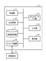
図2は、一つの実施形態による画像処理装置1のハードウェア構成図である。図2に示される通り、投影部7は、設置面または地面と水平に設置され、少なくとも文字または図形を含む文書に付加情報を投影するための投影面を規定し、文書上に重畳画像を投影することが出来る。なお、説明の便宜上、文書上の投影面を文書投影面と称することとする。また、投影部7と、2台の撮像素子2は、例えば文書投影面の上方に、鉛直下向きの方向で設置される。2台の撮像素子2は、内部パラメータが等しく既知であり、互いの光軸が平行で、かつ、2台の撮像素子2が撮像する複数の画像中の任意の横軸が同一直線状上になる様に配置される、所謂平行ステレオ配置となる。撮像素子2により、文書投影面、文書の色情報、ならびに文書の深度、ユーザ指先の深度などの情報を含む画像が撮像されることになる。なお、2台の撮像素子2は、平行ステレオ配置を保った状態で可動させる配置にしても良い。これにより、例えば、文書の文字方向を任意の画像処理方法で推定し、文書の文字方向に平行に(換言すると、文字方向に垂直にならない様に)、平行ステレオ配置を保つことで文書の深度を高い精度で算出できる。また、投影部7により重畳画像が文書投影面上に投影される。ユーザは、任意の方向から指先を文書投影面上に提示し、投影された重畳画像に対してインタラクション操作を行う。なお、図2において、撮像素子2ならびに投影部7以外の図1に開示される各機能は、例えば、図示しないASICの集積回路により構成され、投影部7と同位置に配置されれば良い。
FIG. 2 is a hardware configuration diagram of the
なお、図2に示す画像処理装置1の構成時点で、撮像素子2の撮像素子認識座標系と投影部7の投影部表示座標系の間の位置合わせ(キャリブレーション)は、予め実施されているものとする。また、画像処理装置1に使用開始後に、撮像素子2と投影部7の位置関係を変化させる場合は、キャリブレーションを、少なくとも一回実行すれば良い。ここで、具体的なキャリブレーションの方法の一例として、投影部7が投影する任意の投影画像を撮像素子2で撮像することで、画像処理装置1内部でキャリブレーションを実行する方法を説明する。なお、当該方法においては、2台の撮像素子2それぞれについて、キャリブレーションが実行される。
Note that at the time of the configuration of the
先ず、投影部7は、投影部表示座標系において、ある任意の座標値(xp、yp)に対して任意のマーカを投影する。当該マーカは、周囲の背景と区別しやすいような任意の色や形状を用いることが可能である。そして、撮像素子2は、所定の投影面に投影されたマーカを撮像する。続いて、画像処理装置1は、マーカを公知の任意の画像処理によって認識する。例えば、画像処理装置1は、投影部7がマーカとして円形の模様を投影した場合、「Kimmeら、“Finding circles by an array of accumulators”, Communications of the Association for Computing Machinery, #18, pp.120-122, 1975.」に開示される、ハフ円変換により円形状を認識することが出来る。ここで、画像処理装置1がマーカを認識した際の座標値を(xi、yi)とする。画像処理装置1は、上述の処理を、任意の場所で4点分繰り返す。画像処理装置1は、当該処理で得られた(xp、yp)に対応する(xi、yi)の組の4組から、3行3列のホモグラフィ行列Hの各成分を、8次元連立一次方程式を用いて算出する。なお、ホモグラフィとは、三次元空間上のある平面から別の平面への射影変換を表す行列である。実施例1においては、画像処理装置1は、撮像素子2の撮像素子座標平面と投影部7の投影部座標平面との対応付けを求める。画像処理装置1は、算出して求めたホモグラフィ行列を、例えば、記憶部8に保存しておくことで、重畳画像の投影時においてホモグラフィ行列を利用することが出来る。
First, the
(取得部3の画像取得処理)
図1の取得部3は、撮像素子2が撮像する画像を撮像素子2から受け取る。なお、実施例1においては、撮像素子2は、少なくとも2台ステレオ配置され、複数の撮像素子2は、同時または連続的に画像を撮像するものとする。また、撮像素子2が撮像する画像の解像度は、画像処理装置1の処理速度などに応じて任意の値を用いることが可能である。また、取得部3が取得する画像には、例えば、文字または図形を含む文書、または、ユーザの指先が含まれているものとする。なお、文字または図形を含む文書を第1対象物と称し、ユーザの指先を第2対象物と称しても良い。取得部3は取得した画像を算出部4と抽出部5へ出力する。
(Image acquisition process of acquisition unit 3)
The
(算出部4の3次元直交座標と平坦度情報の算出処理)
図1の算出部4は、取得部3から画像を受け取る。算出部4は、画像処理装置1の処理開始時点、または、画像処理装置1の処理中に、画像から文書投影面の三次元形状、すなわち文書投影面の3次元直交座標を算出する。実施例1においては、算出部4は、コーナーなどの特徴的な模様が存在しない領域でも3次元直交座標を算出することが出来る様に、アクティブステレオ法と称される方法により文書投影面の3次元直交座標を算出する。アクティブステレオ法は、物体に対して投影部7により付加情報の一つとなる特定パターンを投影し、撮像素子2を介して投影した特定パターンの画素の変化を計測することで、物体の3次元直交座標を算出する方法である。
(Calculation process of 3D orthogonal coordinates and flatness information by the calculation unit 4)
The
アクティブステレオ法には様々な種類があり、算出部4は、何れの種類を適用することが可能であるが、例えば、特公平3−56402号公報に記載の空間コード法を用いることが出来る。算出部4は、空間コード法により、投影部7が複数回投影する、明暗をパターン化した特定パターンの全画素の座標をIDとして、投影パターンの画素の変化を算出する。その結果を用いることで、算出部4は、三角測量により投影部7が投影する特定パターンの各画素に対する深度(m)を算出することが出来る。なお、投影部7の任意の基準点に対する各画素の座標と深度を用いることで、算出部4は、第1対象物となる文書の文書投影面の3次元直交座標を規定することが出来る。なお、各画素の座標の基準点は、例えば、取得部3が取得する画像の左上端と規定することが出来る。また、深度の基準点は、例えば、投影部7が設定される位置を基準点とすることが出来る。
There are various types of active stereo methods, and the
図3は、算出部4が算出する第1対象物の投影面の3次元直交座標のデータ構造の一例を示すテーブルである。図3のテーブル30に示される通り、文書投影面の3次元直交座標として、投影部7の任意の基準点に対する各画素の座標と、深度の座標が格納される。なお、テーブル30は、算出部4の図示しないキャッシュまたはメモリに格納されても良いし、記憶部8に記憶されても良い。
FIG. 3 is a table showing an example of the data structure of the three-dimensional orthogonal coordinates of the projection plane of the first object calculated by the
算出部4は、取得部3から受け取った複数の画像に対して、第2対象物の3次元直交座標となる、ユーザの指先の位置の算出を行う。算出部4は、指先の位置を算出する方法として、例えば、特許第3863809号に開示される、画像処理による指先位置を推定する手法や、「山下ら、“3次元Active Appearance Model を用いた手形状認識”、画像の認識・理解シンポジウム、MIRU2012, IS3-70, 2012-08」に開示される、予め手の形状に関する学習データを保持しておき、現時刻で取得した画像と学習データの間の類似度を計算して指先形状を推定する方法など、様々な公知の方法を用いることが可能である。実施例1においては、説明の便宜上、算出部4は、上述の特許第3863809号に開示されている方法を用いるものとして以降の説明を行う。当該方法では、算出部4は、取得部3から受け取った画像から、例えば肌色の色成分部分を抜き出す(抽出する)ことで、手領域輪郭を抽出する。その後、算出部4は、手の本数を認識した上で手領域輪郭から指先座標の算出を行う。なお、算出部4は、肌色の色成分の抽出は、RGB空間やHSV空間の適切な閾値調整を用いることが出来る。
The
図4(a)は、算出部4が算出する指先座標を含むデータ構造の一例を示すテーブルである。図4(a)のテーブル40には、2台の撮像素子2のIDが格納される。また、テーブル40には、例えば、ユーザが片手で指を広げた場合における、2台の撮像素子2それぞれが撮像する画像から算出される各指先の指先座標が、指先IDと対応付けられて格納される。指先IDは、例えば、横方向の座標の小さい順に付与されれば良い。なお、各指先画素の座標の基準点は、例えば、取得部3が取得する画像の左上端と規定することが出来る。また、テーブル40は、算出部4の図示しないキャッシュまたはメモリに格納されても良いし、記憶部8に記憶されても良い。
FIG. 4A is a table showing an example of a data structure including fingertip coordinates calculated by the
続いて、算出部4は、ユーザの指先の深度算出を行う。実施例1においては、2台の撮像素子2(換言するとステレオカメラ)によるユーザの指先の深度算出について説明する。算出部4は、3次元空間となる3次元直交座標の任意の基準点に対する奥行方向の深度Zを、2台の撮像素子2の間の線分の長さ(基線長)をb、撮像素子2の焦点距離をf、左右の対応する二次元直交座標をそれぞれ(u、v)、(u’、v’)とすると、三角測量の原理により次式で算出することが出来る。
(数1)
![]()
算出部4は、上述の(数1)を用いて、指先となる各指の頂点部分の深度を算出する。なお、焦点距離fを算出するための撮像素子2の内部パラメータ推定には、例えば、「Zhangら、“A flexible new technique for camera calibration”, IEEE Transactions on Pattern Analysis and Machine Intelligence, 22(11), pp.1330-1334, 2000.」に開示されるキャリブレーション方法を用いることが出来る。
Subsequently, the
(Equation 1)
![]()
The
算出部4は、例えば、図2に示す通り、左右に複数配置される撮像素子2で横方向の座標の小さい順に、指先点にIDを付与し、同一IDの指先点同士を対応点と見なし、それぞれの対応点について上述の(数1)に代入して深度Zを算出する。図4(b)は、算出部4が算出する指先の深度を含むデータ構造の一例を示すテーブルである。図4(b)のテーブル41において、指先IDは、図4(a)のテーブル40の指先IDと同一のIDが付与され、各指先IDに対応する深度が格納される。なお、当該深度の基準点は、例えば、投影部7が設定される位置を基準点とすることが出来る。また、図4(b)のテーブル41は、算出部4の図示しないキャッシュまたはメモリに格納されても良いし、記憶部8に記憶されても良い。
For example, as illustrated in FIG. 2, the
算出部4は、図4(a)のテーブル40と図4(b)のテーブル41のデータ構造を利用して、第2対象物となるユーザの指先の3次元直交座標を規定する。図5は、算出部4が算出する、第2対象物となるユーザの指先の3次元直交座標のデータ構造の一例を示すテーブルである。図5のテーブル50において指先IDと、深度は図4(b)のテーブル41のデータ構造と同一である。また、指先座標は、図4(a)のテーブル40に開示される指先座標を各指先ID毎に平均した座標となる。なお、図5のテーブル50において、指先座標の基準点は、例えば、取得部3が取得する画像の左上端と規定することが出来る。また、深度の基準点は、例えば、投影部7が設定される位置を基準点とすることが出来る。図5のテーブル50は、算出部4の図示しないキャッシュまたはメモリに格納されても良いし、記憶部8に記憶されても良い。
The
(抽出部5による表示候補領域の抽出処理)
図1の抽出部5は、取得部3から画像を受け取り、重畳画像を投影する表示候補領域を抽出する。なお、抽出部5は、表示候補領域を抽出する場合に、必要に応じてユーザの指先の押下判定を実施しても良い。実施例1においては、抽出部5が、指先と文書投影面との接触を検知することで押下判定を実施する例を説明する。抽出部5は、算出部4が、画像処理装置1の処理開始時に算出する、上述のアクティブステレオ法による文書投影面の深度を予め取得しておき、指先の深度が文書投影面の深度に対する所定の閾値範囲内に収まっているときに押下されたことを検知することが出来る。なお、複数の指先の深度が閾値範囲内に収まっている場合は、抽出部5は、複数の指先が押下しているものとみなすことが出来る。
(Extraction processing of display candidate area by extraction unit 5)
The
抽出部5は、少なくとも1本以上の指先が文書投影面に対して押下されたことを検出した場合、表示候補領域の抽出を行う。実施例1では、抽出部5は、例えば、「Liuら、“Embedded Media Markers: Marks on Paper that Signify Associated Media”, In proc. of IUI, pp.149-158, 2010.」に開示されているレイアウト解析手法を一部利用することで表示候補領域の抽出する方法を説明する。先ず、抽出部5は、投影部7が投影を実施する予定の重畳画像の大きさの取得を、例えば、記憶部8に記憶されている図示しないテーブルから実施する。なお、当該テーブルに格納される重畳画像の大きさは、具体的には、重畳画像を矩形状に近似した際の縦横長(pixel)であり、例えば、(縦、横)=(50、60)という値である。
When the
続いて、抽出部5は、取得部3から取得した画像をグレースケール化する。次に、抽出部5は、当該グレースケール化した画像に対して、コーナー点の特徴点抽出を行う。抽出部5は、例えば、「Harrisら、“A Combined Corner and Edge Detector”, In proc. of the Alvey Vision Conference, pp.147-151, 1988.」に開示されるHarrisオペレータや、「Rostenら、“FASTER and better: A machine learning approach to corner detection”, IEEE Trans. Pattern Analysis and Machine Intelligence, vol.32, pp.105-119, 2008.」に開示されるFASTなど、任意のコーナー点の特徴点抽出手法を用いることが出来る。図6は、抽出部5が抽出する特徴点IDと、特徴点座標のデータ構造の一例を示すテーブルである。図6のテーブル60に示す様に、抽出部5は、特徴点を抽出する毎に特徴点IDを付与し、当該特徴点が抽出された特徴点座標と対応づける。なお、特徴点座標の原点となる基準点は、例えば、取得部3が取得する画像の左上端であれば良い。
Subsequently, the
次に、抽出部5は、特徴点分布計測を行う。抽出部5は、取得部3から取得する画像を、例えば、5(pixel)四方のブロックに分解し、格子点Xと画像の任意の原点からなる矩形内に含まれる特徴点の個数Ng(X)を計測する。この場合、任意の矩形領域ABCD内に含まれる特徴点の数は、Ng(C)+Ng(A)−Ng(B)−Ng(D)となる。但し、基準点となる原点から最も近い点をAとし、原点から最も遠い点をCとする。抽出部5は、当該特徴点分布計測を全ての格子点Xについて繰り返す。図7は、抽出部5が抽出する特徴点分布のデータ構造の一例を示すテーブルである。図7のテーブル70に示される通り、上述の任意の矩形領域ABCDに対して、格子点ID(x)が付与され、当該格子点ID(x)に対応付けられて、格子点座標と特徴点数が格納される。なお、テーブル70は、抽出部5の図示しないキャッシュまたはメモリに格納されても良いし、記憶部8に記憶されても良い。
Next, the
次に、抽出部5は、表示候補領域探索を行う。抽出部5は、予め取得した重畳画像の大きさ領域について、取得部3から取得した画像の左上端から右下端まで上述のブロックおきにスライドさせ、それぞれの領域の特徴点数Nを計測し、所定の特徴点数閾値Nt(例えばNt=10)以下となる場合、その矩形領域を表示候補領域と見なす。なお、特徴点数閾値Ntを下回る表示候補領域が存在しなかった場合は、抽出部5は、特徴点数閾値Ntを所定の一定数増加させて、再度表示候補領域が存在するか否かの判定を実施する。当該判定により、特徴点が画像全体に渡って多く分布する画像であっても、何れかの場所に重畳画像を表示することが可能となる。以上に説明した方法を用いて抽出部5は、表示候補領域を抽出することが出来る。
Next, the
(算出部4の3次元直交座標と平坦度情報の算出処理)
算出部4は、表示候補領域の平坦度に基づく利用可能度の算出を実施する。算出部4は、抽出部5による表示候補領域探索により得られた表示候補領域それぞれについて、算出部4が算出する第1対象物の投影面の3次元直交座標と第2対象物の3次元直交座標などを用いて利用可能度pを、次式を用いて規定する。なお、利用可能度p、は0以上1以下の範囲を持つ値であり、値が大きくなるほど重畳画像の表示に適していることを示す。
(数2)
![]()
上述の(数2)において、ptはコーナーの有無による重畳画像の視認性の項(換言すると、表示候補領域に含まれるコーナーの頻度に関する項)であり、次式で表現される。
(数3)
![]()
上述の(数3)から理解出来る通りptは、表示候補領域に含まれるコーナー数が少ないほど高い値となる。なお、(数3)において、αはコーナーの許容度を意味しており、画像処理装置1の適用用途に応じて適宜設定することが出来るが、例えば、α=2と設定することが出来る。
(Calculation process of 3D orthogonal coordinates and flatness information by the calculation unit 4)
The
(Equation 2)
![]()
In the above equation (2), p t is (in other words, section on the frequency of a corner included in the display candidate region) term of visibility of the superimposed image by the presence or absence of the corner is, is expressed by the following equation.
(Equation 3)
![]()
As p t which can be understood from the above equation (3) becomes a higher value is smaller corner number included in the display candidate region. In (Equation 3), α means the tolerance of the corner and can be set as appropriate according to the application application of the
上述の(数2)において、pfは、ユーザの手領域と重畳画像の重複防止に関する項(換言すると、手領域への重畳画像の投影を防ぐ項)であり、次式で表現される。
(数4)
![]()
算出部4は、pfを算出する為に、算出部4が算出する上述の手領域輪郭を利用し、手領域を規定する。算出部4は、表示候補領域のピクセル数Asと、表示候補領域であり、かつ手領域である部分のピクセル数Asfを計算し、上述の(数4)を用いてpfを算出する。pfの項により、手のひらの様なコーナー点が存在しないが、投影には適さない領域への重畳画像の投影を防止することが出来る。
In the above (Equation 2), pf is a term related to prevention of overlap between the user's hand region and the superimposed image (in other words, a term that prevents projection of the superimposed image onto the hand region), and is expressed by the following equation.
(Equation 4)
![]()
上述の(数2)において、pcは、文書投影面の平坦度に関する項(換言すると、文書投影面の表示候補領域における凹凸の程度を示した項)であり、次式で表現される。
(数5)

算出部4は、表示候補領域について、第1対象物の投影面の3次元直交座標からcの値を計算することが出来る。なお、上述の(数5)において、cは、凹凸の頻度を表すccと、凹凸による重畳画像の隠れによる不可視領域の頻度を示すcoとの線形和となっており、ccとcoは、それぞれ操作性と視認性に影響を与えるものであるが、ccは特に操作性、coは特に視認性に影響を与える。なお、上述の(数5)から理解出来る通り、ccやcoの値が大きくなるにつれてpcの値は小さくなり、利用可能度が減少する。なお、(数5)において、di、jは表示候補領域内の座標(i、j)における深度(m)とし、I,Jを表示候補領域の横、縦のピクセル数とする。なお、ccの項を第1対象物の投影面の平坦度に関する平坦度情報と称しても良い。
In the above (Equation 2), pc is a term relating to the flatness of the document projection plane (in other words, a term indicating the degree of unevenness in the display candidate area of the document projection plane), and is expressed by the following equation.
(Equation 5)
The
上述の(数5)において、ccは表示候補領域内における隣接ピクセル間での深度の差分を表示候補領域全体に渡り合計した値である。ccが大きいと、凹凸が頻繁に存在することになり、平坦度が低くなる。凹凸の大きい領域への投影は、押下時の操作性や視認性の低下に起因する為、凹凸が大きい領域を避けるためにccの項を適用する。図8(a)は、表示候補領域にペン等の障害物が置かれている場合のccの概念図である。図8(b)は、表示候補領域にたわみが生じている場合のccの概念図である。図8(c)は、表示候補領域が本と本の間などの場所に存在する場合のccの概念図である。図8(a)ないし図8(c)に示すグラフは、横軸に画像のx方向またはy方向、縦軸に投影部7の設置点に対する深度の分布例を示している。ccは、凹凸が多い程(平坦度が低い程)、大きい値を示す。
In the above (Equation 5), cc is a value obtained by summing the depth difference between adjacent pixels in the display candidate region over the entire display candidate region. When c c is large, unevenness is frequently present and flatness is lowered. Projection of the unevenness of a large area, because due to the reduction in pressing time of the operation and visibility is applied to the section c c in order to avoid uneven large area. 8 (a) is a conceptual diagram of a c c when the obstacle such as a pen is placed in the display candidate region. 8 (b) is a conceptual diagram of a c c in the case where the deflection in the display candidate areas has occurred. FIG. 8 (c), the display candidate region is a conceptual diagram of a c c when present in places such as between books and books. The graphs shown in FIGS. 8A to 8C show distribution examples of the depth with respect to the installation point of the
上述の(数5)において、coは、重畳画像の隠れによる不可視領域に関係する深度の差分値dpを、表示候補領域全体に渡り合計した値である。dpは、画像の下方向を正としたときに、正方向に深度値が減少している時は、その深度値の絶対値、それ以外の時は0の値を取る。図9は、重畳画像の隠れによる不可視領域の概念図である。実施例1における画像処理装置1では、ユーザは投影部7の下方から指先を出してインタクティブ操作するものと想定している。この為、図9に示す通り、ユーザの視点の高さや角度に応じて、表示候補領域の凹凸の影響で重畳画像が隠れ、視認性が低下する場合がある。図9から理解出来る通り、重畳画像の隠れが生じるのは正方向に深度が減少している時である為、算出部4は、この時の深度の差分値を領域全体について足し合わせcoの値を算出する。coの値が大きいほど、隠れる領域の面積が大きいことを意味する。ここでβはccに関するcoの影響度を意味しており、用途に応じて選択出来るが、通常β=2程度の値を用いる。
In the above equation (5), c o is the differential value d p of the depth related to the invisible region by hidden superimposed image is the sum value over the entire display candidate region. Assuming that the downward direction of the image is positive, d p takes an absolute value of the depth value when the depth value decreases in the positive direction, and takes a value of 0 otherwise. FIG. 9 is a conceptual diagram of an invisible region due to hiding of the superimposed image. In the
以上により、算出部4が算出するcの値を用い、cと所定の任意の閾値θcの大小によりpcの値を決定することが出来る。なお、閾値θcは、画像処理装置1の用途によって適宜変化させることが出来るが、例えば0.01(m)という値を使用することが出来る。
なお、pcの項を表示候補領域の基準点に対する分散と称し、閾値θcを第1閾値と称しても良い。図10は、算出部4が算出する表示候補領域に関するデータ構造の一例を示すテーブルである。図10のテーブル100には、表示候補領域IDそれぞれについて、表示候補領域の左上端座標、含有特徴点数、利用可能度が格納されている。
Thus, using the value of c for calculating
Incidentally, it referred to as the dispersion with respect to the reference point of the display candidate region section of the p c, may be referred to threshold θc first threshold value. FIG. 10 is a table showing an example of a data structure related to the display candidate area calculated by the
(規定部6による重畳画像の表示位置の規定処理)
図1の規定部6は、重畳画像の表示位置の規定を実施する。規定部6は、図10のテーブル100に示される利用可能度や、上述の(数5)から算出される平坦度情報に基づいて重畳画像の表示位置を規定(複数の表示候補領域から一つの領域を規定)することが出来る。また、規定部6は、指先座標と、表示候補領域候補の間のユークリッド距離を計算し、ユークリッド距離が最小となる表示候補領域を表示位置と規定しても良い。規定部6は、上述の処理を用いて重畳画像の表示位置を規定し、当該重畳画像の表示位置を投影部7に出力する。
(Defining process of display position of superimposed image by defining unit 6)
1 defines the display position of the superimposed image. The defining
規定部6は、重畳画像の表示位置の規定後、重畳画像の表示状態決定を実施しても良い。即ち、規定部6は、文書の記載状態に応じて、重畳画像の表示状態(補色関係、文書の行の方向、文書の文字の大きさ)をユーザが可読し易い適切な状態に変化させても良い。補色関係については、表示候補領域の投影先の色情報と補色関係にある色を用いて重畳画像を表示する。また、文書の行の方向については、規定部6は、特開平11−219407号公報に開示される方法により、予め行の方向を取得しておく。そして規定部6は、文書中の文字と重畳画像の文字の方向を一致させる。文字のサイズに関しては、例えば、特開平11−219407号公報に開示される方法を用いて、表示候補領域の近傍に存在する文字の大きさを取得する。そして規定部6は、重畳画像の文字サイズは文書中の文字サイズ以上の値とし、重畳画像を表示する表示候補領域の領域を超過しないような値とする。なお、規定部6は、表示位置を規定した後、表示領域を一定程度拡大縮小して各領域での利用可能度を再計算して、利用可能度が最大の大きさに微調整することを実施しても良い。この様な処理を実施することで、重畳画像を適切な大きさで投影させることも可能となる為、重畳画像の内容に関する視認性低下を防止することが出来る。操作性の観点については、手に近い場所に重畳画像を投影することで、インタラクション操作に要する時間を削減することが出来る。また、重畳画像をインタラクション操作に適切なサイズで投影させるため、ユーザの押下等の操作ミスを減少させることが可能となる。
The defining
規定部6は、重畳画像の表示位置を投影部7に出力し、投影部7に対して当該表示位置への重畳画像の投影と、表示領域の更新を実行させる。また、規定部は、表示領域に関し、予め取得している撮像素子2の撮像素子認識座標系と投影部7の投影部表示座標系との間のホモグラフィ行列から、次式により重畳画像を投影する投影面の座標(換言すると重畳画像の表示位置となる平面直交座標)を決定する。例えば、(xsrc、ysrc)を撮像素子2の撮像素子認識座標系での表示位置の中心座標、(xdst、ydst)を投影部7の投影部表示座標系での表示位置の中心座標とする。また、次式において、h11ないしh33までの各成分は、上述のキャリブレーションで得られているホモグラフィ行列の逆行列H^−1である。
(数6)
(Equation 6)
図11は、重畳画像の投影例を含む画像処理装置1の使用例を示す図である。図11に示す様に、投影される重畳画像は、文書に対しインタラクティブ操作を実行したい領域を指先で指定した時の領域(選択済領域)に関する情報と、その領域に対して加えるインタラクティブ操作のメニュー領域の二種類が存在する。指先による操作で領域を指定する際は、領域の矩形の端点の部分で指先を文書が存在する面、すなわち、文書投影面で接触させ、接触させたまま指先を矩形のもう片方の端点まで動かし、端点に到達した時に指先を投影面から離す。接触しているか否か判定は、上述の抽出部5によるによる押下判定を用いれば良い。対象領域の指定中は、対象領域に関する重畳画像が表示されることになる。
FIG. 11 is a diagram illustrating a usage example of the
上記の領域指定後、指先を使ったインタラクション操作を行うことの出来る重畳画像(メニュー領域)が表示される。ユーザは、指先により領域選択した文書の内容を画像で保存したい場合、メニューの中の「COPY」という場所に指先を合わせ押下することで、選択領域の部分画像を、記憶部8に記憶することが出来る。
After the above-described area designation, a superimposed image (menu area) that allows an interaction operation using the fingertip is displayed. When the user wants to save the contents of the document whose area has been selected by the fingertip as an image, the user can store a partial image of the selected area in the
図11に示される通り、ユーザによる選択済領域に対するインタラクション操作の為にメニュー領域の重畳画像を投影させる場合、実施例1を適用することで、文書領域やペンなど凹凸領域を避け、かつ、指先に一番近い表示候補領域に表示させることが可能となる。図12は、実施例1の比較例となる重畳画像の投影例を示す図である。図12に示す、比較例においては、特徴点のみから表示候補領域をランダムに規定して投影しているものとする。比較例の方法では、図12に示す通り、重畳画像の投影領域として本の段差部が選択されることが有り得るが、この様な平坦性が低い領域は視認性や操作性が低下するため、重畳画像の表示位置には適していないことが理解出来る。 As shown in FIG. 11, when a superimposed image of a menu area is projected for an interaction operation on a selected area by a user, by applying the first embodiment, an uneven area such as a document area or a pen is avoided, and a fingertip It is possible to display in the display candidate area closest to. FIG. 12 is a diagram illustrating a projection example of a superimposed image that is a comparative example of the first embodiment. In the comparative example shown in FIG. 12, it is assumed that display candidate regions are randomly defined and projected only from feature points. In the method of the comparative example, as shown in FIG. 12, it is possible that a stepped portion of a book is selected as the projection region of the superimposed image. However, in such a region with low flatness, visibility and operability are reduced. It can be understood that it is not suitable for the display position of the superimposed image.
実施例1によれば、視認性かつ操作性を考慮して最適な場所に重畳画像を投影させることが可能となる。視認性の観点からは、文書領域でない領域に重畳画像を投影することで、文字や図などの文書と重畳画像の重複が防げ、文書と重畳画像双方の視認性が向上する。また、平坦度が低い領域に重畳画像を投影することで、凹凸による重畳画像の歪みの影響を低減出来る。加えて、平坦度が低いに重畳画像を投影することで、ユーザが自然に重畳画像を操作可能な対象であると認識することができ(アフォーダンスの活用)、操作性が向上する。 According to the first embodiment, it is possible to project a superimposed image on an optimal place in consideration of visibility and operability. From the viewpoint of visibility, by projecting a superimposed image onto a region that is not a document region, it is possible to prevent overlapping of the document such as characters and drawings and the superimposed image, and the visibility of both the document and the superimposed image is improved. In addition, by projecting the superimposed image on an area with low flatness, the influence of the distortion of the superimposed image due to unevenness can be reduced. In addition, by projecting the superimposed image with low flatness, it can be recognized that the user can operate the superimposed image naturally (utilization of affordance), and operability is improved.
図13は、画像処理装置1による画像処理のフローチャートである。取得部3は、撮像素子2が撮像する画像を撮像素子2から受け取る(ステップS1301)。なお、実施例1においては、撮像素子2は、少なくとも2台ステレオ配置され、複数の撮像素子2は、同時または連続的に画像を撮像するものとする。取得部3が取得する画像には、例えば、文字または図形を含む文書、または、ユーザの指先が含まれているものとする。なお、文字または図形を含む文書を第1対象物と称し、ユーザの指先を第2対象物と称しても良い。取得部3は取得した画像を算出部4と抽出部5へ出力する。
FIG. 13 is a flowchart of image processing by the
算出部4は、取得部3から画像を受け取り、上述の方法を用いて第1対象物の投影面の3次元直交座標と第2対象物の3次元直交座標を算出する(ステップS1302、S1303)。なお、算出部4が算出する第1対象物の投影面の3次元直交座標と第2対象物の3次元直交座標のデータ構造は、例えば、図3に示すテーブル30と図5に示すテーブル50となる。
The
抽出部5は、取得部3から画像を受け取り、上述のアクティブステレオ法を用いてユーザの指先の押下判定を実施する(ステップS1304)。抽出部5は、少なくとも1本以上の指先が文書投影面に対して押下されたことを検出した場合(ステップS1304−Yes)、表示候補領域の抽出を行う(ステップS1305)。抽出部5は、指先が文書投影面に対して押下されたことを検出しない場合(ステップS1304−No)は、画像処理を終了するか、前時刻において重畳画像を投影している場合は、そのまま投影を継続する。
The
算出部4は、表示候補領域の平坦度情報や利用可能度を上述の(数2)ないし(数5)を用いて算出する。算出部4が算出する利用可能度のデータ構造は、例えば、図10に示すテーブル100となる。
The
規定部6は、重畳画像の表示位置の規定を実施する(ステップS1307)。規定部8は、図10のテーブル100に示される利用可能度や、上述の(数5)から算出される平坦度情報に基づいて重畳画像の表示位置を規定(複数の表示候補領域から一つの領域を規定)する。規定部6は、重畳画像の表示位置を投影部7に出力する。
The defining
投影部7は、重畳画像を第1対象物の投影面に対して規定部6が規定する位置に投影する(ステップS1308)ことで、画像処理装置1は、図13に示す画像処理を終了する。
The
(実施例2)
実施例1では複数の撮像素子2(ステレオカメラ)を用いた画像処理装置1の構成で実施例を説明したが、ステレオカメラの代わりにカメラ1台と深度センサー1台を用いる場合でも、本発明の実施は可能である為、実施例2において説明する。実施例2における画像処理装置1画像処理装置1のハードウェア構成図は、図2に示すハードウェア構成図の2つの撮像素子2の何れかを深度センサーに置換すれば実現可能の為、図示は省略する。深度センサーには、レーザー光の往復時間から深度を計測するTOF形式や、特定のパターンのレーザー光線を対象に照射した際の光のパターンの歪みを計測するパターン照射方式などがあり、実施例2では何れの方式を採用することが出来る。なお、撮像素子2と深度センサーは文書投影面の上方部に、鉛直下向きの方向で設置される。撮像素子2の内部パラメータは実施例1と同様に既知であり、深度センサーと撮像素子2の光軸は平行であり、画像中の横軸が同一直線状になるように配置される。なお、実施例2における画像処理装置1の機能ブロック図は図1と同様である。
(Example 2)
In the first embodiment, the embodiment has been described with the configuration of the
実施例2においては、深度センサーを用いることで手領域輪郭と深度を算出することが出来る。算出部4は、距離画像と称される、深度センサーから取得されるデータを用いる。なお、距離画像は通常の二次元画像の色や濃淡の値の代わりに、深度センサーから対象物までの距離の値を持った画像である。実施例2では、画像処理の開始以前に学習過程が必要となる。当該学習過程では、例えば、図1の記憶部8に、図示しないデータベースに手の距離画像に関するテンプレートを多数記憶する。次に、それぞれの距離画像から、ユーザが手動で手領域の切り出しと指先座標の指定を実施する。手輪郭領域は一定の大きさに正規化され、記憶部8に保存される。実施例2においては、画像処理装置1は、一定のテンプレートが得られるまで上述の学習処理を繰り返す。
In the second embodiment, the hand region contour and the depth can be calculated by using the depth sensor. The
実施例2において、画像処理の開始後は、算出部4は、深度センサーから、現時刻における距離画像を取得する。その後、任意の倍率を有する窓を用いて距離画像を走査する。それぞれの窓では、窓中の距離画像と全てのテンプレートの間の類似度を計算し、最も類似度の高いテンプレートを選択するというテンプレートマッチングを行うことが出来る。なお、類似度の算出の一例として、SSD(Sum of Squared Difference)や、NCC(Normalized Cross−Correlation) などが用いることが出来る。算出部4は、テンプレートマッチングによる最適なテンプレートの選択後、最適なテンプレート内に保持されている手指の位置情報を取得し、現在の距離画像で手指位置に対応する深度の値を取得する。当該処理で取得されるデータ構造は、図4(b)に示すテーブル41と同一となる。その他の処理は実施例1と同様の為、詳細な説明は省略する。
In the second embodiment, after the image processing is started, the
(実施例3)
図14は、一つの実施形態による画像処理装置1として機能するコンピュータのハードウェア構成図である。図14に示すように、画像処理装置1は、制御部9、主記憶部10、補助記憶部11、ドライブ装置12、ネットワークI/F部14、入力部15、表示部16を含む。これら各構成は、バスを介して相互にデータ送受信可能に接続されている。
(Example 3)
FIG. 14 is a hardware configuration diagram of a computer that functions as the
制御部9は、コンピュータの中で、各装置の制御やデータの演算、加工を行うCPUである。また、制御部9は、主記憶部10や補助記憶部11に記憶されたプログラムを実行する演算装置であり、入力部15や記憶装置からデータを受け取り、演算、加工した上で、表示部16や記憶装置などに出力する。
The
主記憶部10は、ROMやRAMなどであり、制御部9が実行する基本ソフトウェアであるOSやアプリケーションソフトウェアなどのプログラムやデータを記憶または一時保存する記憶装置である。
The
補助記憶部11は、HDDなどであり、アプリケーションソフトウェアなどに関連するデータを記憶する記憶装置である。
The
ドライブ装置12は、記録媒体13、例えばフレキシブルディスクからプログラムを読み出し、補助記憶部11にインストールする。また、記録媒体13に、所定のプログラムを格納し、この記録媒体13に格納されたプログラムはドライブ装置12を介して画像処理装置1にインストールされる。インストールされた所定のプログラムは、画像処理装置1により実行可能となる。
The
ネットワークI/F部14は、有線及び/又は無線回線などのデータ伝送路により構築されたLAN(Local Area Network)、WAN(Wide Area Network)などのネットワークを介して接続された通信機能を有する周辺機器と画像処理装置1とのインターフェースである。
The network I /
入力部15は、カーソルキー、数字入力及び各種機能キー等を備えたキーボード、表示部16の表示画面上でキーの選択等を行うためのマウスやスライスパット等を有する。また、入力部15は、ユーザが制御部9に操作指示を与えたり、データを入力したりするためのユーザインタフェースである。
The
表示部16は、CRT(Cathode Ray Tube)やLCD(Liquid Crystal Display)等により構成され、制御部9から入力される表示データに応じた表示が行われる。また、表示部16として、図1に示す投影部7を適用することが可能である。
The
なお、上述した画像処理方法は、コンピュータに実行させるためのプログラムとして実現されてもよい。このプログラムをサーバ等からインストールしてコンピュータに実行させることで、上述した画像処理方法を実現することが出来る。 The image processing method described above may be realized as a program for causing a computer to execute. The above-described image processing method can be realized by installing this program from a server or the like and causing the computer to execute it.
また、このプログラムを記録媒体13に記録し、このプログラムが記録された記録媒体13をコンピュータや携帯端末に読み取らせて、前述した画像処理を実現させることも可能である。なお、記録媒体13は、CD−ROM、フレキシブルディスク、光磁気ディスク等の様に情報を光学的、電気的或いは磁気的に記録する記録媒体、ROM、フラッシュメモリ等の様に情報を電気的に記録する半導体メモリ等、様々なタイプの記録媒体を用いることが出来る。
It is also possible to record the program on the
また、図示した各装置の各構成要素は、必ずしも物理的に図示の如く構成されていることを要しない。すなわち、各装置の分散・統合の具体的形態は図示のものに限られず、その全部または一部を、各種の負荷や使用状況などに応じて、任意の単位で機能的または物理的に分散・統合して構成することが出来る。また、上記の実施例で説明した各種の処理は、予め用意されたプログラムをパーソナルコンピュータやワークステーションなどのコンピュータで実行することによって実現することが出来る。 In addition, each component of each illustrated apparatus does not necessarily need to be physically configured as illustrated. In other words, the specific form of distribution / integration of each device is not limited to that shown in the figure, and all or a part thereof may be functionally or physically distributed or arbitrarily distributed in arbitrary units according to various loads or usage conditions. Can be integrated and configured. The various processes described in the above embodiments can be realized by executing a prepared program on a computer such as a personal computer or a workstation.
以上、説明した実施形態に関し、更に以下の付記を開示する。
(付記1)
撮像素子が撮像する第1対象物を含む画像を取得する取得部と、
付加情報を含む重畳画像が前記第1対象物に対して重畳表示される、前記第1対象物の投影面の平坦度に関する平坦度情報を前記画像から算出する算出部と、
前記平坦度情報に基づいて、前記重畳画像の表示位置を規定する規定部と、
を備えることを特徴とする画像処理装置。
(付記2)
前記第1対象物に対して所定の特徴量数に基づく表示候補領域を抽出する抽出部を更に備え、
前記規定部は、前記平坦度情報度と前記表示候補領域に基づいて、前記付加情報の表示位置を規定することを特徴とする付記1記載の画像処理装置。
(付記3)
前記取得部が取得する画像は、前記撮像素子が撮像する第2対象物を更に含み、
前記算出部は、前記画像から前記第1対象物の3次元直交座標と、前記第2対象物の3次元直交座標とを算出し、
前記規定部は、前記第1対象物の前記投影面の3次元直交座標から規定される前記平坦度情報と、前記第2対象物の3次元直交座標と、前記表示候補領域とに基づいて、前記表示位置となる平面直交座標を規定する
ことを特徴とする付記2記載の画像処理装置。
(付記4)
前記算出部は、前記第2対象物となるユーザの指先の3次元直交座標を、複数の前記画像に含まれる前記指先の座標と、前記3次元直交座標の基準点に基づいて算出することを特徴とする付記3記載の画像処理装置。
(付記5)
前記重畳画像を前記第1対象物に投影する投影部を更に備え、
前記算出部は、前記第1対象物となる文字または図形を含む、前記投影面の3次元直交座標を、複数の前記画像に含まれる重畳画像の画素の変化量に基づいて算出することを特徴とする付記1ないし付記4いずれか一つに記載の画像処理装置。
(付記6)
前記規定部は、前記第1対象物の前記投影面の3次元直交座標から規定される、複数の前記表示候補領域の前記基準点に対する分散に基づいて、前記平面直交座標を規定することを特徴とする付記3ないし付記5いずれか一つに記載の画像処理装置。
(付記7)
前記規定部は、複数の前記表示候補領域のうち、前記分散が第1閾値以下の前記表示候補領域を選択して、前記平面直交座標を規定することを特徴とする付記6に記載の画像処理装置。
(付記8)
前記規定部は、前記投影部と前記第2対象物の相対位置に基づいて、前記重畳画像の平面直交座標を規定することを特徴とする付記5記載の画像処理装置。
(付記9)
撮像素子が撮像する第1対象物を含む画像を取得し、
付加情報を含む重畳画像が前記第1対象物に対して重畳表示される、前記第1対象物の投影面の平坦度に関する平坦度情報を前記画像から算出し、
前記平坦度情報に基づいて、前記重畳画像の表示位置を規定する
ことを含むことを特徴とする画像処理方法。
(付記10)
前記第1対象物に対して所定の特徴量数に基づく表示候補領域を抽出し、
前記規定することは、前記平坦度情報度と前記表示候補領域に基づいて、前記付加情報の表示位置を規定することを特徴とする付記9記載の画像処理方法。
(付記11)
前記取得することが取得する画像は、前記撮像素子が撮像する第2対象物を更に含み、
前記算出することは、前記画像から前記第1対象物の3次元直交座標と、前記第2対象物の3次元直交座標とを算出し、
前記規定することは、前記第1対象物の前記投影面の3次元直交座標から規定される前記平坦度情報と、前記第2対象物の3次元直交座標と、前記表示候補領域とに基づいて、前記表示位置となる平面直交座標を規定する
ことを特徴とする付記10記載の画像処理方法。
(付記12)
前記算出することは、前記第2対象物となるユーザの指先の3次元直交座標を、複数の前記画像に含まれる前記指先の座標と、前記3次元直交座標の基準点に基づいて算出することを特徴とする付記11記載の画像処理方法。
(付記13)
前記重畳画像を前記第1対象物に投影し、
前記算出することは、前記第1対象物となる文字または図形を含む、前記投影面の3次元直交座標を、複数の前記画像に含まれる重畳画像の画素の変化量に基づいて算出することを特徴とする付記9ないし付記12いずれか一つに記載の画像処理方法。
(付記14)
前記規定することは、前記第1対象物の前記投影面の3次元直交座標から規定される、複数の前記表示候補領域の前記基準点に対する分散に基づいて、前記平面直交座標を規定することを特徴とする付記11ないし付記13いずれか一つに記載の画像処理方法。
(付記15)
前記規定することは、複数の前記表示候補領域のうち、前記分散が第1閾値以下の前記表示候補領域を選択して、前記平面直交座標を規定することを特徴とする付記14に記載の画像処理方法。
(付記16)
前記規定することは、前記投影部と前記第2対象物の相対位置に基づいて、前記重畳画像の平面直交座標を規定することを特徴とする付記13記載の画像処理方法。
(付記17)
コンピュータに、
撮像素子が撮像する第1対象物を含む画像を取得し、
付加情報を含む重畳画像が前記第1対象物に対して重畳表示される、前記第1対象物の投影面の平坦度に関する平坦度情報を前記画像から算出し、
前記平坦度情報に基づいて、前記重畳画像の表示位置を規定する
ことを実行させることを特徴とする画像処理プログラム。
The following supplementary notes are further disclosed with respect to the embodiment described above.
(Appendix 1)
An acquisition unit that acquires an image including a first object imaged by the imaging element;
A calculation unit that calculates, from the image, flatness information related to the flatness of the projection surface of the first object, wherein a superimposed image including additional information is superimposed on the first object;
A defining unit for defining a display position of the superimposed image based on the flatness information;
An image processing apparatus comprising:
(Appendix 2)
An extractor for extracting a display candidate area based on a predetermined number of features for the first object;
The image processing apparatus according to
(Appendix 3)
The image acquired by the acquisition unit further includes a second object captured by the image sensor,
The calculation unit calculates a three-dimensional orthogonal coordinate of the first object and a three-dimensional orthogonal coordinate of the second object from the image,
The defining unit is based on the flatness information defined from the three-dimensional orthogonal coordinates of the projection plane of the first object, the three-dimensional orthogonal coordinates of the second object, and the display candidate region. The image processing apparatus according to
(Appendix 4)
The calculation unit calculates the three-dimensional orthogonal coordinates of the user's fingertip as the second object based on the coordinates of the fingertips included in the plurality of images and a reference point of the three-dimensional orthogonal coordinates. The image processing apparatus according to
(Appendix 5)
A projection unit that projects the superimposed image onto the first object;
The calculation unit calculates a three-dimensional orthogonal coordinate of the projection plane including a character or a figure to be the first object based on a change amount of a pixel of a superimposed image included in the plurality of images. The image processing apparatus according to any one of
(Appendix 6)
The defining unit defines the planar orthogonal coordinates based on a variance of the plurality of display candidate regions with respect to the reference point, which is defined from three-dimensional orthogonal coordinates of the projection plane of the first object. The image processing apparatus according to any one of
(Appendix 7)
The image processing according to
(Appendix 8)
The image processing apparatus according to
(Appendix 9)
Obtaining an image including a first object imaged by the imaging device;
A flatness information related to the flatness of the projection surface of the first object is calculated from the image, and a superimposed image including additional information is superimposed on the first object, and is calculated from the image.
An image processing method comprising: defining a display position of the superimposed image based on the flatness information.
(Appendix 10)
Extracting a display candidate area based on a predetermined number of features for the first object;
The image processing method according to
(Appendix 11)
The image to be acquired further includes a second object captured by the image sensor,
The calculating calculates a three-dimensional orthogonal coordinate of the first object and a three-dimensional orthogonal coordinate of the second object from the image;
The defining is based on the flatness information defined from the three-dimensional orthogonal coordinates of the projection surface of the first object, the three-dimensional orthogonal coordinates of the second object, and the display candidate region. The image processing method according to
(Appendix 12)
The calculating includes calculating the three-dimensional orthogonal coordinates of the fingertip of the user as the second object based on the coordinates of the fingertips included in the plurality of images and the reference point of the three-dimensional orthogonal coordinates. The image processing method according to
(Appendix 13)
Projecting the superimposed image onto the first object;
The calculating includes calculating a three-dimensional orthogonal coordinate of the projection plane including a character or a figure as the first object based on a change amount of pixels of a superimposed image included in the plurality of images. The image processing method according to any one of
(Appendix 14)
The defining includes defining the plane orthogonal coordinates based on a variance of the plurality of display candidate regions with respect to the reference point, which is defined from three-dimensional orthogonal coordinates of the projection plane of the first object. 14. The image processing method according to any one of
(Appendix 15)
15. The image according to
(Appendix 16)
14. The image processing method according to
(Appendix 17)
On the computer,
Obtaining an image including a first object imaged by the imaging device;
A flatness information related to the flatness of the projection surface of the first object is calculated from the image, and a superimposed image including additional information is superimposed on the first object, and is calculated from the image.
An image processing program for causing the display position of the superimposed image to be defined based on the flatness information.
1 画像処理装置
2 撮像素子
3 取得部
4 算出部
5 抽出部
6 規定部
7 投影部
8 記憶部
DESCRIPTION OF
Claims (10)
取得した前記画像に含まれ、付加情報を含む重畳画像が重畳表示される第1対象物の投影面の平坦度に関する平坦度情報を前記画像に基づいて算出する算出部と、
前記平坦度情報が所定の基準よりも平坦であることを示す位置に、前記重畳画像の表示位置を規定する規定部と、
を備えることを特徴とする画像処理装置。 An acquisition unit for acquiring a captured image;
Contained in the acquired image, and a calculation unit for calculating, based flatness information on the image relating to the flatness of the projection plane of the first object superimposed image including additional information is Ru are superimposed,
A defining unit that defines the display position of the superimposed image at a position indicating that the flatness information is flatter than a predetermined reference;
An image processing apparatus comprising:
前記規定部は、前記平坦度情報と前記表示候補領域に基づいて、前記付加情報の表示位置を規定することを特徴とする請求項1記載の画像処理装置。 An extractor for extracting a display candidate area based on a predetermined number of features for the first object;
The image processing apparatus according to claim 1, wherein the defining unit defines a display position of the additional information based on the flatness information and the display candidate area.
前記算出部は、前記画像から前記第1対象物の3次元直交座標と、前記第2対象物の3次元直交座標とを算出して、算出した前記第1対象物の3次元直交座標に基づいて前記平坦度情報を算出し、
前記規定部は、前記平坦度情報と、前記第2対象物の3次元直交座標と、前記表示候補領域とに基づいて、前記表示位置に対応する平面直交座標を規定する
ことを特徴とする請求項2記載の画像処理装置。 The image acquired by the acquisition unit further includes a second object,
The calculation unit calculates a three-dimensional orthogonal coordinate of the first object and a three-dimensional orthogonal coordinate of the second object from the image, and based on the calculated three-dimensional orthogonal coordinate of the first object. To calculate the flatness information,
The said prescription | regulation part prescribes | regulates the plane orthogonal coordinate corresponding to the said display position based on the said flatness information, the three-dimensional orthogonal coordinate of the said 2nd target object, and the said display candidate area | region. Item 3. The image processing apparatus according to Item 2.
前記算出部は、前記第1対象物となる文字または図形を含む、前記投影面の3次元直交座標を、複数の前記画像に含まれる重畳画像の画素の変化量に基づいて算出することを特徴とする請求項1ないし請求項4いずれか一項に記載の画像処理装置。 A projection unit that projects the superimposed image onto the first object;
The calculation unit calculates a three-dimensional orthogonal coordinate of the projection plane including a character or a figure to be the first object based on a change amount of a pixel of a superimposed image included in the plurality of images. The image processing apparatus according to any one of claims 1 to 4.
前記算出部は、前記第1対象物となる文字または図形を含む、前記投影面の3次元直交座標を、複数の前記画像に含まれる重畳画像の画素の変化量に基づいて算出し、
前記規定部は、前記投影部と前記第2対象物の相対位置に基づいて、前記重畳画像の平面直交座標を規定することを特徴とする請求項3記載の画像処理装置。 A projection unit that projects the superimposed image onto the first object;
The calculation unit calculates a three-dimensional orthogonal coordinate of the projection plane including a character or a figure as the first object based on a change amount of pixels of a superimposed image included in the plurality of images,
The image processing apparatus according to claim 3, wherein the defining unit defines a plane orthogonal coordinate of the superimposed image based on a relative position between the projection unit and the second object.
撮像された画像を取得し、
取得した前記画像に含まれ、付加情報を含む重畳画像が重畳表示される第1対象物の投影面の平坦度に関する平坦度情報を前記画像に基づいて算出し、
前記平坦度情報が所定の基準よりも平坦であることを示す位置に、前記重畳画像の表示位置を規定する
ことを含むことを特徴とする画像処理方法。 Computer
Acquire the captured image,
Contained in the acquired image, calculated on the basis of the flatness information on the image relating to the flatness of the projection plane of the first object superimposed image including additional information is Ru are superimposed,
An image processing method comprising: defining a display position of the superimposed image at a position indicating that the flatness information is flatter than a predetermined reference.
撮像された画像を取得し、
取得した前記画像に含まれ、付加情報を含む重畳画像が重畳表示される第1対象物の投影面の平坦度に関する平坦度情報を前記画像に基づいて算出し、
前記平坦度情報が所定の基準よりも平坦であることを示す位置に、前記重畳画像の表示位置を規定する
ことを実行させることを特徴とする画像処理プログラム。 On the computer,
Acquire the captured image,
Contained in the acquired image, calculated on the basis of the flatness information on the image relating to the flatness of the projection plane of the first object superimposed image including additional information is Ru are superimposed,
An image processing program that causes the display position of the superimposed image to be defined at a position indicating that the flatness information is flatter than a predetermined reference.
Priority Applications (2)
| Application Number | Priority Date | Filing Date | Title |
|---|---|---|---|
| JP2013010425A JP6089722B2 (en) | 2013-01-23 | 2013-01-23 | Image processing apparatus, image processing method, and image processing program |
| US14/082,586 US9405182B2 (en) | 2013-01-23 | 2013-11-18 | Image processing device and image processing method |
Applications Claiming Priority (1)
| Application Number | Priority Date | Filing Date | Title |
|---|---|---|---|
| JP2013010425A JP6089722B2 (en) | 2013-01-23 | 2013-01-23 | Image processing apparatus, image processing method, and image processing program |
Publications (2)
| Publication Number | Publication Date |
|---|---|
| JP2014143548A JP2014143548A (en) | 2014-08-07 |
| JP6089722B2 true JP6089722B2 (en) | 2017-03-08 |
Family
ID=51207354
Family Applications (1)
| Application Number | Title | Priority Date | Filing Date |
|---|---|---|---|
| JP2013010425A Expired - Fee Related JP6089722B2 (en) | 2013-01-23 | 2013-01-23 | Image processing apparatus, image processing method, and image processing program |
Country Status (2)
| Country | Link |
|---|---|
| US (1) | US9405182B2 (en) |
| JP (1) | JP6089722B2 (en) |
Families Citing this family (20)
| Publication number | Priority date | Publication date | Assignee | Title |
|---|---|---|---|---|
| JP6361332B2 (en) * | 2014-07-04 | 2018-07-25 | 富士通株式会社 | Gesture recognition apparatus and gesture recognition program |
| JP6478502B2 (en) * | 2014-07-11 | 2019-03-06 | キヤノン株式会社 | Information processing apparatus, information processing method, and program |
| WO2016018393A1 (en) | 2014-07-31 | 2016-02-04 | Hewlett-Packard Development Company, Lp | Touch region projection onto a touch-sensitive surface |
| US10310675B2 (en) * | 2014-08-25 | 2019-06-04 | Canon Kabushiki Kaisha | User interface apparatus and control method |
| JP6643825B2 (en) * | 2014-08-25 | 2020-02-12 | キヤノン株式会社 | Apparatus and method |
| JP2016045882A (en) * | 2014-08-26 | 2016-04-04 | 株式会社東芝 | Image processor and information processor |
| WO2016053269A1 (en) | 2014-09-30 | 2016-04-07 | Hewlett-Packard Development Company, L. P. | Displaying an object indicator |
| JP2016099742A (en) * | 2014-11-19 | 2016-05-30 | 株式会社東芝 | Information processing device, video projection device, information processing method and program |
| WO2017110732A1 (en) * | 2015-12-24 | 2017-06-29 | 株式会社ソニー・インタラクティブエンタテインメント | Main beam direction determination device, main beam direction determination method, and program |
| JP6607121B2 (en) * | 2016-03-30 | 2019-11-20 | セイコーエプソン株式会社 | Image recognition apparatus, image recognition method, and image recognition unit |
| CN106055092A (en) * | 2016-05-18 | 2016-10-26 | 广景视睿科技(深圳)有限公司 | Method and system for implementing interactive projection |
| JP6452658B2 (en) * | 2016-09-27 | 2019-01-16 | キヤノン株式会社 | Information processing apparatus, control method thereof, and program |
| JP7098884B2 (en) * | 2017-05-31 | 2022-07-12 | 富士フイルムビジネスイノベーション株式会社 | Inspection equipment and programs |
| JP7129839B2 (en) * | 2018-07-19 | 2022-09-02 | 三菱重工業株式会社 | TRAINING APPARATUS, TRAINING SYSTEM, TRAINING METHOD, AND PROGRAM |
| JP7367776B2 (en) * | 2019-12-27 | 2023-10-24 | 株式会社ソシオネクスト | Image processing device, image processing method, and image processing program |
| CN112150527B (en) * | 2020-08-31 | 2024-05-17 | 深圳市慧鲤科技有限公司 | Measurement method and device, electronic equipment and storage medium |
| JP7163947B2 (en) * | 2020-10-22 | 2022-11-01 | セイコーエプソン株式会社 | Projection area setting support method, setting support system, and program |
| CN112329588B (en) * | 2020-10-30 | 2024-01-05 | 中海石油(中国)有限公司 | Pipeline fault detection method based on Faster R-CNN |
| CN113763419B (en) * | 2021-04-29 | 2023-06-20 | 腾讯科技(深圳)有限公司 | Target tracking method, device and computer readable storage medium |
| US11579747B1 (en) | 2022-03-14 | 2023-02-14 | Snap Inc. | 3D user interface depth forgiveness |
Family Cites Families (14)
| Publication number | Priority date | Publication date | Assignee | Title |
|---|---|---|---|---|
| JPH0780722B2 (en) | 1989-07-21 | 1995-08-30 | ソマール株式会社 | Molded article containing sustained-release antibacterial agent |
| JPH09319556A (en) * | 1996-05-28 | 1997-12-12 | Matsushita Electric Ind Co Ltd | Information processor |
| JP4170441B2 (en) | 1997-11-28 | 2008-10-22 | 富士通株式会社 | Document image inclination detection apparatus and storage medium for document image inclination detection program |
| JP2003315912A (en) | 2002-04-19 | 2003-11-06 | Institute Of Tsukuba Liaison Co Ltd | Electronic projection display system |
| JP3863809B2 (en) | 2002-05-28 | 2006-12-27 | 独立行政法人科学技術振興機構 | Input system by hand image recognition |
| JP2006031506A (en) * | 2004-07-20 | 2006-02-02 | Brother Ind Ltd | Image input-output apparatus |
| US7916932B2 (en) * | 2005-02-16 | 2011-03-29 | In-G Co., Ltd. | Method and system of structural light-based 3D depth imaging using signal separation coding and error correction thereof |
| JP4680640B2 (en) * | 2005-03-16 | 2011-05-11 | 株式会社リコー | Image input apparatus and image input method |
| US8786682B2 (en) * | 2009-03-05 | 2014-07-22 | Primesense Ltd. | Reference image techniques for three-dimensional sensing |
| JP2011043545A (en) | 2009-08-19 | 2011-03-03 | Brother Industries Ltd | Image display device |
| JP2011250198A (en) | 2010-05-27 | 2011-12-08 | Aisin Aw Co Ltd | Information input device |
| US20120042288A1 (en) | 2010-08-16 | 2012-02-16 | Fuji Xerox Co., Ltd. | Systems and methods for interactions with documents across paper and computers |
| JP5216834B2 (en) | 2010-11-08 | 2013-06-19 | 株式会社エヌ・ティ・ティ・ドコモ | Object display device and object display method |
| US9070194B2 (en) * | 2012-10-25 | 2015-06-30 | Microsoft Technology Licensing, Llc | Planar surface detection |
-
2013
- 2013-01-23 JP JP2013010425A patent/JP6089722B2/en not_active Expired - Fee Related
- 2013-11-18 US US14/082,586 patent/US9405182B2/en not_active Expired - Fee Related
Also Published As
| Publication number | Publication date |
|---|---|
| JP2014143548A (en) | 2014-08-07 |
| US9405182B2 (en) | 2016-08-02 |
| US20140204120A1 (en) | 2014-07-24 |
Similar Documents
| Publication | Publication Date | Title |
|---|---|---|
| JP6089722B2 (en) | Image processing apparatus, image processing method, and image processing program | |
| JP6417702B2 (en) | Image processing apparatus, image processing method, and image processing program | |
| JP5201096B2 (en) | Interactive operation device | |
| JP6007497B2 (en) | Image projection apparatus, image projection control apparatus, and program | |
| CN107251101B (en) | Scene modification for augmented reality using markers with parameters | |
| US9807263B2 (en) | Mobile document capture assistance using augmented reality | |
| JP6248533B2 (en) | Image processing apparatus, image processing method, and image processing program | |
| US9519968B2 (en) | Calibrating visual sensors using homography operators | |
| US10310675B2 (en) | User interface apparatus and control method | |
| US20120249422A1 (en) | Interactive input system and method | |
| US20130201210A1 (en) | Virtual ruler | |
| US10642422B2 (en) | Information processing apparatus, control method for the information processing apparatus, and storage medium | |
| JP2014063397A (en) | Image processor, image processing method and image processing program | |
| JP6028589B2 (en) | Input program, input device, and input method | |
| US10747371B1 (en) | Detection of finger press from live video stream | |
| JP2014029656A (en) | Image processor and image processing method | |
| JP2016103137A (en) | User interface system, image processor and control program | |
| JP2017199288A (en) | Image processing device, image processing method and program | |
| WO2020095400A1 (en) | Characteristic point extraction device, characteristic point extraction method, and program storage medium | |
| JP2016139396A (en) | User interface device, method and program | |
| JP6815712B1 (en) | Image processing system, image processing method, image processing program, image processing server, and learning model | |
| US11734940B2 (en) | Display apparatus, display method, and non-transitory recording medium | |
| CN118550394A (en) | AR-based handwriting practicing auxiliary method, device, equipment and storage medium | |
| TW201229924A (en) | Method of using singular value decompostion for processing hand gesture images with complex background and a system thereof | |
| Das et al. | Preprocessing and Screen-Cursor Mapping for a Virtual TouchScreen on a Projected Area |
Legal Events
| Date | Code | Title | Description |
|---|---|---|---|
| A621 | Written request for application examination |
Free format text: JAPANESE INTERMEDIATE CODE: A621 Effective date: 20150903 |
|
| RD01 | Notification of change of attorney |
Free format text: JAPANESE INTERMEDIATE CODE: A7421 Effective date: 20160401 |
|
| A977 | Report on retrieval |
Free format text: JAPANESE INTERMEDIATE CODE: A971007 Effective date: 20160707 |
|
| A131 | Notification of reasons for refusal |
Free format text: JAPANESE INTERMEDIATE CODE: A131 Effective date: 20160719 |
|
| A521 | Request for written amendment filed |
Free format text: JAPANESE INTERMEDIATE CODE: A523 Effective date: 20160909 |
|
| A131 | Notification of reasons for refusal |
Free format text: JAPANESE INTERMEDIATE CODE: A131 Effective date: 20161004 |
|
| A521 | Request for written amendment filed |
Free format text: JAPANESE INTERMEDIATE CODE: A523 Effective date: 20161202 |
|
| TRDD | Decision of grant or rejection written | ||
| A01 | Written decision to grant a patent or to grant a registration (utility model) |
Free format text: JAPANESE INTERMEDIATE CODE: A01 Effective date: 20170110 |
|
| A61 | First payment of annual fees (during grant procedure) |
Free format text: JAPANESE INTERMEDIATE CODE: A61 Effective date: 20170123 |
|
| R150 | Certificate of patent or registration of utility model |
Ref document number: 6089722 Country of ref document: JP Free format text: JAPANESE INTERMEDIATE CODE: R150 |
|
| LAPS | Cancellation because of no payment of annual fees |