JP6084823B2 - Interface device and control method thereof - Google Patents
Interface device and control method thereof Download PDFInfo
- Publication number
- JP6084823B2 JP6084823B2 JP2012257387A JP2012257387A JP6084823B2 JP 6084823 B2 JP6084823 B2 JP 6084823B2 JP 2012257387 A JP2012257387 A JP 2012257387A JP 2012257387 A JP2012257387 A JP 2012257387A JP 6084823 B2 JP6084823 B2 JP 6084823B2
- Authority
- JP
- Japan
- Prior art keywords
- signal
- time axis
- mode
- rectangular wave
- operator
- Prior art date
- Legal status (The legal status is an assumption and is not a legal conclusion. Google has not performed a legal analysis and makes no representation as to the accuracy of the status listed.)
- Active
Links
- 238000000034 method Methods 0.000 title claims description 100
- 230000008569 process Effects 0.000 claims description 80
- 238000001514 detection method Methods 0.000 claims description 34
- 230000003321 amplification Effects 0.000 claims description 16
- 238000003199 nucleic acid amplification method Methods 0.000 claims description 16
- 230000001537 neural effect Effects 0.000 claims description 13
- 210000002569 neuron Anatomy 0.000 claims description 9
- 230000000630 rising effect Effects 0.000 claims description 5
- 230000007423 decrease Effects 0.000 claims description 3
- 230000008859 change Effects 0.000 claims description 2
- 230000007274 generation of a signal involved in cell-cell signaling Effects 0.000 claims 2
- 230000003247 decreasing effect Effects 0.000 claims 1
- 230000002496 gastric effect Effects 0.000 claims 1
- 238000010586 diagram Methods 0.000 description 17
- 210000005036 nerve Anatomy 0.000 description 17
- 230000005540 biological transmission Effects 0.000 description 12
- 238000006243 chemical reaction Methods 0.000 description 12
- 238000004891 communication Methods 0.000 description 11
- 230000003183 myoelectrical effect Effects 0.000 description 11
- 210000003205 muscle Anatomy 0.000 description 10
- 238000003672 processing method Methods 0.000 description 8
- 238000005286 illumination Methods 0.000 description 6
- 210000004699 muscle spindle Anatomy 0.000 description 6
- 108091008709 muscle spindles Proteins 0.000 description 6
- 210000001087 myotubule Anatomy 0.000 description 6
- 206010002026 amyotrophic lateral sclerosis Diseases 0.000 description 5
- 238000001816 cooling Methods 0.000 description 5
- 238000007791 dehumidification Methods 0.000 description 5
- 238000010438 heat treatment Methods 0.000 description 5
- 238000009423 ventilation Methods 0.000 description 5
- 210000003414 extremity Anatomy 0.000 description 3
- 230000006870 function Effects 0.000 description 3
- 238000007918 intramuscular administration Methods 0.000 description 3
- 230000004048 modification Effects 0.000 description 3
- 238000012986 modification Methods 0.000 description 3
- 210000002027 skeletal muscle Anatomy 0.000 description 3
- 210000004556 brain Anatomy 0.000 description 2
- 230000008602 contraction Effects 0.000 description 2
- 238000010304 firing Methods 0.000 description 2
- 239000004973 liquid crystal related substance Substances 0.000 description 2
- 210000001044 sensory neuron Anatomy 0.000 description 2
- 210000005252 bulbus oculi Anatomy 0.000 description 1
- 210000002310 elbow joint Anatomy 0.000 description 1
- 230000004424 eye movement Effects 0.000 description 1
- 238000001914 filtration Methods 0.000 description 1
- 210000002585 gamma motor neuron Anatomy 0.000 description 1
- 210000001503 joint Anatomy 0.000 description 1
- 230000003287 optical effect Effects 0.000 description 1
- 239000013307 optical fiber Substances 0.000 description 1
- 238000003909 pattern recognition Methods 0.000 description 1
- 230000001953 sensory effect Effects 0.000 description 1
- 210000000323 shoulder joint Anatomy 0.000 description 1
- 230000007704 transition Effects 0.000 description 1
- 210000003857 wrist joint Anatomy 0.000 description 1
Images


Landscapes
- Measurement And Recording Of Electrical Phenomena And Electrical Characteristics Of The Living Body (AREA)
- User Interface Of Digital Computer (AREA)
Description
本発明は神経細胞から得られる生体信号を外部機器に出力するインターフェイス装置及びその制御方法に関する。 The present invention relates to an interface device that outputs a biological signal obtained from a nerve cell to an external device and a control method thereof.
例えば重度の障害者から筋電位信号、脳波、呼気、眼の動き、手足の動き等の生体信号を検出し、当該筋電位等の生体信号に基づいてアクチュエータ装置を動作させて障害者を支援する支援システムがある(例えば、特許文献1参照)。また、この支援システムでは、障害者(操作者)から検出した生体信号をデータベースに登録されたパターンデータと比較することで、当該障害者が希望するパターンを認識してアクチュエータ装置が所定の動作を行うことで当該障害者に対する作業支援を可能にしている。 For example, biological signals such as myoelectric potential signals, brain waves, expiration, eye movements, limb movements, etc. are detected from severely disabled persons, and the actuator device is operated based on the biological signals such as myoelectric potentials to assist the disabled persons. There is a support system (see, for example, Patent Document 1). Further, in this support system, by comparing the biological signal detected from the disabled person (operator) with the pattern data registered in the database, the actuator device recognizes the pattern desired by the disabled person and performs a predetermined operation. This enables work support for the disabled.
また、筋萎縮性側索硬化症(ALS:Amyotrophic Lateral Sclerosis)の場合、例えば手足を自由に動かすことができないばかりか呼吸することも難しいような障害者からの筋電位を検出することが難しく、極めて微弱な信号を検出できたとしても当該障害者自身の意思との関係性を確認することが困難であった。 In addition, in the case of amyotrophic lateral sclerosis (ALS), for example, it is difficult to detect a myoelectric potential from a disabled person who cannot move his limbs freely and is difficult to breathe, Even if a very weak signal could be detected, it was difficult to confirm the relationship with the disabled person's own intention.
従来は、上記パターン認識システムでは、筋電位信号等の生体信号のパターンをデータベースに登録する必要がある。そして、障害者から検出された生体信号をデータベースに登録されたパターンと比較して当該障害者の意思を認識する方式のため、例えば筋萎縮性側索硬化症の場合のように、筋電位自体が十分に検出できない場合、予め本人による生体信号のパターンを登録することができないことから、別人(例えば健常者)の筋電位に対応する動作パターンを登録せざるをえない。
そのため、従来は、検出された筋電位が微弱な場合、検出された筋電位と予め登録されたパターンとが正確に一致しないことから、アクチュエータ装置に入力される制御信号が本人の意思に対応していないことがあり、アクチュエータ装置を正確に動作制御することが難しかった。
Conventionally, in the pattern recognition system, it is necessary to register biosignal patterns such as myoelectric potential signals in a database. The bioelectric signal detected from the disabled person is compared with the pattern registered in the database to recognize the intention of the disabled person. For example, as in the case of amyotrophic lateral sclerosis, the myoelectric potential itself If the signal cannot be detected sufficiently, it is impossible to register the biological signal pattern by the person in advance, and thus an operation pattern corresponding to the myoelectric potential of another person (for example, a healthy person) must be registered.
Therefore, conventionally, when the detected myoelectric potential is weak, the detected myoelectric potential does not exactly match the pre-registered pattern, so the control signal input to the actuator device corresponds to the intention of the person. In some cases, it was difficult to accurately control the operation of the actuator device.
そこで、本発明は上記事情に鑑み、上記課題を解決したインターフェイス装置及びその制御方法の提供を目的とする。 In view of the above circumstances, an object of the present invention is to provide an interface device and a control method therefor that solve the above-described problems.
上記課題を解決するため、本発明は以下のような手段を有する。
(1)本発明は、操作者の皮膚の異なる箇所に貼り付けられ、当該操作者の神経細胞から生成される神経信号をそれぞれ検出する複数の信号検出センサと、複数の信号検出センサより得られた各神経信号の差分に基づく電位を所定電圧値に増幅して、時間軸上においてゼロ電位から+側に立ち上り、最大値に達すると、−側に低下した後、再び+側に推移しながらゼロ電位に戻る傾向を示す生体信号を出力する差動増幅器と、差動増幅器により増幅された生体信号をアナログ信号のまま所定周波数範囲のみ通過させて増幅して出力する増幅・フィルタ回路と、増幅・フィルタ回路により増幅されたアナログ信号の生体信号をデジタル変換するA/D変換器と、デジタル化された生体信号の電位と予め設定された+側の閾値とを比較し、当該閾値以上になった時点の立ち上がりエッジの一定時間内の連続数が所定数を越えた時点を始点とし、かつ、当該始点から所定時間の経過時点を終点とする矩形波信号を出力する出力信号生成手段と、矩形波信号を、当該矩形波信号の時間軸長さに応じた操作内容が予め割り当てられている外部機器に送信する送信手段とを備え、出力信号生成手段は、矩形波信号の始点を常時検出し、最初の始点から所定時間の経過時までに次の始点を検出した場合には、当該検出された次の始点を基準に所定時間の経過時まで終点を延長することにより、矩形波信号の時間軸長さを変更することを特徴とする。
(2)本発明は、操作者の皮膚の異なる箇所において、当該操作者の神経細胞から生成される神経信号をそれぞれ検出する第1の過程と、第1の過程より得られた各神経信号の差分に基づく電位を所定電圧値に増幅して、時間軸上においてゼロ電位から+側に立ち上がり、最大値に達すると、−側に低下した後、再び+側に推移しながらゼロ電位に戻る傾向を示す生体信号を出力する第2の過程と、第2の過程により増幅された生体信号をアナログ信号のまま所定周波数範囲のみ通過させて増幅して出力する第3の過程と、第3の過程により増幅されたアナログ信号の生体信号をデジタル変換する第4の過程と、第4の過程によりデジタル化された生体信号の電位と予め設定された+側の閾値とを比較し、当該閾値以上になった時点の立ち上がりエッジの一定時間内の連続数が所定数を越えた時点を始点とし、かつ、当該始点から所定時間の経過時点を終点とする矩形波信号を出力する第5の過程と、矩形波信号を、当該矩形波信号の時間軸長さに応じた操作内容が予め割り当てられている外部機器に送信する第6の過程とを行い、第5の過程では、矩形波信号の始点を常時検出し、最初の始点から所定時間の経過時までに次の始点を検出した場合には、当該検出された次の始点を基準に所定時間の経過時まで終点を延長することにより、矩形波信号の時間軸長さを変更することを特徴とする。
In order to solve the above problems, the present invention has the following means.
(1) The present invention is obtained from a plurality of signal detection sensors and a plurality of signal detection sensors, each of which is affixed to a different part of the operator's skin and detects nerve signals generated from the operator's nerve cells. The potential based on the difference between each neural signal is amplified to a predetermined voltage value, rises from the zero potential to the + side on the time axis, and when reaching the maximum value, decreases to the − side and then transitions to the + side again. A differential amplifier that outputs a biological signal that tends to return to zero potential, an amplification / filter circuit that amplifies and outputs the biological signal amplified by the differential amplifier while passing through a predetermined frequency range as an analog signal, and amplification The A / D converter that digitally converts the biological signal of the analog signal amplified by the filter circuit is compared with the potential of the digitized biological signal and a preset positive threshold, and the threshold Output signal generating means for outputting a rectangular wave signal starting from the time when the number of consecutive rising edges within a certain time exceeds a predetermined number, and ending after a predetermined time from the starting point And a transmission means for transmitting the rectangular wave signal to an external device preliminarily assigned with the operation content corresponding to the time axis length of the rectangular wave signal, and the output signal generating means determines the starting point of the rectangular wave signal. If the next start point is detected from the first start point until the elapse of the predetermined time, the end point is extended until the elapse of the predetermined time with reference to the detected next start point. The time axis length of the signal is changed.
(2) The present invention relates to a first process for detecting neural signals generated from the nerve cells of the operator at different locations on the operator's skin, and each neural signal obtained from the first process. The potential based on the difference is amplified to a predetermined voltage value, rises from zero potential to the + side on the time axis, and when it reaches the maximum value, it decreases to the-side and then returns to the zero potential while transitioning to the + side again A second process for outputting a biological signal indicating the above, a third process for amplifying the biological signal amplified in the second process by passing only a predetermined frequency range as an analog signal, and a third process The fourth step of digitally converting the biological signal of the analog signal amplified by the
本発明によれば、神経細胞から生成される神経信号に相当する生体信号による時系列的な時間軸データを作成して外部機器に出力するため、例えば微弱な信号しか検出できないような操作者でも、外部機器を操作することが可能になる。 According to the present invention, time-series time axis data based on biological signals corresponding to nerve signals generated from nerve cells is created and output to an external device. For example, even an operator who can detect only weak signals can be used. It becomes possible to operate an external device.
以下、図面を参照して本発明を実施するための形態について説明する。 Hereinafter, embodiments for carrying out the present invention will be described with reference to the drawings.
〔インターフェイス装置の構成〕
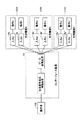
図1Aは本発明によるインターフェイス装置及びその制御方法の一実施例を示すブロック図である。図1Aに示されるように、インターフェイス装置10は、生体信号検出センサ(生体信号検出手段)20と、差動増幅器(増幅手段)30と、増幅・フィルタ回路40と、ADコンバータ50と、制御部(データ変換手段)60と、送信回路(送信手段)70と、モニタ(表示手段)80とを有する。
[Configuration of interface device]
FIG. 1A is a block diagram showing an embodiment of an interface device and a control method thereof according to the present invention. As shown in FIG. 1A, the
生体信号検出センサ(生体信号検出手段)20は、操作者の意思に基づき脳から筋肉に伝達される神経信号に相当する電位(生体信号)を検出する電位検出センサである。また、生体信号検出センサ20は、操作者の皮膚の複数箇所に貼り付けられ、操作者が意識的に生体電位(神経信号)を発生させた場合に得られる生体信号(生体電位信号)をセンサ信号として出力する。また、生体信号検出センサ20は、例えば、重度の障害者等のように手足の筋肉を自由に動かすことができない場合、骨格筋のなかにあって、その伸縮状態を感知する筋紡錘から得られる生体信号(神経信号に相当する電位信号)を検出する。尚、生体信号検出センサ20は、筋紡錘以外の筋肉を動作させる際に生成される電位を生体信号として検出するように操作者に貼り付けても良い。
The biological signal detection sensor (biological signal detection means) 20 is a potential detection sensor that detects a potential (biological signal) corresponding to a nerve signal transmitted from the brain to the muscle based on the intention of the operator. In addition, the biological
筋紡錘は、骨格筋の伸縮を感知しており、錘内筋線維と呼ばれる筋と、それに巻きついた数本の感覚神経終末、錘内筋線維を運動神経支配するガンマ運動ニューロンとから構成されている。また、筋紡錘は、骨格筋線維の間に散在し、それらと平行に並んでいるが、例えば眼球や指など細かくコントロールされた動きをする筋には多く存在する。そして、骨格筋に合わせて錘内筋線維が伸張すると、それに巻きついた感覚神経終末が刺激され固有感覚のインパルスを生じ、筋紡錘による神経信号が検出される。 The muscle spindle senses the expansion and contraction of skeletal muscle, and is composed of muscles called intramuscular muscle fibers, several sensory nerve endings wrapped around them, and gamma motor neurons that innervate muscle fibers inside the spindle. ing. In addition, muscle spindles are scattered between skeletal muscle fibers and aligned in parallel with them, but there are many muscles that move in a finely controlled manner such as the eyeball and fingers. When the intramuscular muscle fiber stretches in accordance with the skeletal muscle, the sensory nerve ending wrapped around the muscle fiber is stimulated to generate a proper sensory impulse, and a nerve signal from the muscle spindle is detected.
例えば、操作者が筋萎縮性側索硬化症の場合、筋肉を動かす際の筋電位は殆ど発生しないことから、重度の障害者の筋電位を検出することは難しい。しかしながら、重度の障害者であっても筋肉の動きは見られないまでも、錘内筋線維が伸縮し信号を発する場合があり、神経信号が発生する箇所に生体信号検出センサ20を貼り付けることで当該神経信号を検出可能になる。尚、神経信号が得られる箇所は、各個人によって様々で異なるため、予め複数の生体信号検出センサ20を当該操作者に装着して生体信号が得られる箇所を探し出しておく。
For example, when the operator has amyotrophic lateral sclerosis, since the myoelectric potential when moving the muscle hardly occurs, it is difficult to detect the myoelectric potential of a severely disabled person. However, even if a person with a severe disability does not see any movement of muscles, the intramuscular muscle fibers may expand and contract to generate a signal, and the biological
差動増幅器30は、複数の生体信号検出センサ20からの各生体信号(神経信号に相当)が入力されると、二つの信号の差分を一定係数(差動利得)で増幅する。従って、差動増幅器30は、複数箇所のうち1箇所あるいは複数箇所で神経信号が得られると、各信号の差に基づく電位を増幅して生体信号を出力する。
When each biological signal (corresponding to a nerve signal) is input from the plurality of biological
増幅・フィルタ回路40は、生体信号の高周波成分を除去して所定の周波数以下の成分だけを通過させるローパスフィルタと、生体信号の低周波成分を除去して所定の周波数以上の成分だけを通過させるハイパスフィルタとを有する。そして、生体信号は、増幅・フィルタ回路40によりノイズ成分が除去され、その後を二つのフィルタ回路を介して取出された所定周波数範囲の生体信号を増幅して出力する。
The amplification /
ADコンバータ50は、増幅・フィルタ回路40及びその他機器からの信号(アナログ信号)をデジタル信号に変換して制御部60に入力する。また、増幅・フィルタ回路40で増幅された生体信号は、制御部60へ直接的に入力されており、制御部60において時間軸データに変換される。
The
制御部60は、制御プログラムを実行するマイクロコンピュータからなり、増幅・フィルタ回路40で増幅された各生体信号を時間軸データに変換して外部機器110へ出力される制御信号を生成する。また、制御部60は、生体信号検出センサ20より得られた生体信号を時間軸データとして変換する時間軸データ変換手段62と、時間軸データに基づく外部機器に応じた制御信号を生成する制御信号変換手段64とを有する。上記制御信号は、各外部機器において判別可能なデータ形式の信号に変換されたものである。
The
また、制御部60は、後述するように、神経細胞から生成される神経信号に相当する生体信号を検出する第1の過程と、第1の過程より得られた生体信号を所定電圧値に増幅する第2の過程と、第2の過程により所定振幅に増幅された生体信号を時間軸データとして変換する第3の過程と、第3の過程により生成された生体信号の時間軸データに対応する制御信号を外部機器を操作する操作信号として当該外部機器に送信する第4の過程と、を実行する制御プログラムがメモリに格納されている。
In addition, as will be described later, the
送信回路70は、近距離無線通信を行う送信機であり、例えばBluetooth(ブルートゥース:登録商標)等の通信システムに対応している。また、送信回路70は、上記制御部60において生体信号に対応する制御信号が生成されると、当該制御信号を無線によりモニタ80の受信回路82に送信する。または、外部機器110に制御信号を送信する外部機器制御部72に送信する。尚、外部機器制御部72は、例えば光あるいは無線あるいは有線などを用いた通信手段に対応するインターフェイスであり、外部機器110の構成や機能に合わせて通信方式が適宜選択される。
The
モニタ80は、表示専用のディスプレイあるいはタブレット型端末装置あるいはスマートホンなどの携帯電話機あるいはパーソナルコンピュータのディスプレイ(液晶パネル)などの表示手段からなり、送信回路70から送信された制御信号を受信する受信回路82を有し、制御信号に応じた画像を表示する。また、モニタ80は、操作者が介護ベットあるいは車椅子を利用している場合、ブラケットなどの支持部材により操作者から見やすい高さ位置、角度に支持されており、後述するモード選択画面200、文字入力画面300、エアコン制御画面500、テレビ制御画面700、照明スイッチ制御画面900などが表示される。そして、操作者は、神経信号を出力することで生成された入力データ(制御信号による指示内容)をモニタ80の表示をみることで、本人が目視により入力されたデータを確認することができ、神経信号と入力データとの関連性を視覚的に認識することが可能になる。
The
また、外部機器110としては、携帯電話機、電子メール送信機、チャット送受信を行うインターネット接続機器等の通信機器があり、その他に通信機能を有する端末装置(例えば、ナースコールのような緊急信号を送受信する緊急連絡機器)などがある。また、外部機器110の取付箇所としては、上記車椅子やストレッチャーなどの移動体やエレベータ、押しボタンを有する信号機などの公共設備などでも良い。
The
〔インターフェイス装置の変形例〕
図1Bは本発明によるインターフェイス装置の変形例を示すブロック図である。図1Bに示されるように、変形例のインターフェイス装置10Aは、モニタ80に接続された外部機器制御部84より外部機器110に制御信号を送信できる。この場合、モニタ80は、通信機能を有するタブレット型端末装置あるいはスマートホンなどの携帯電話機あるいはパーソナルコンピュータのディスプレイ(液晶パネル)であり、後述するモード選択画面200、文字入力画面300、エアコン制御画面500、テレビ制御画面700、照明スイッチ制御画面900などが表示される。
[Modification of interface device]
FIG. 1B is a block diagram showing a modification of the interface device according to the present invention. As illustrated in FIG. 1B, the
インターフェイス装置10Aは、前述したインターフェイス装置10と外部機器制御部84がモニタ80側に配置されている点が異なる構成であり、主要部(生体信号検出センサ20、差動増幅器30、増幅・フィルタ回路40、ADコンバータ50、制御部60、送信回路70)は同じ構成である。そのため、操作者は上記インターフェイス装置10、10Aの中から使いやすい何れかの方式を任意に選択することが可能になる。
The
図2は本発明のインターフェイス装置10を外部機器に接続した場合の構成例を模式的に示す図である。図2に示されるように、インターフェイス装置10は、操作者100と外部機器110との間に介在し、生体信号検出センサ20により操作者から検出された神経信号に相当する生体信号が検出されると、増幅・フィルタ回路40により識別可能なレベルまで増幅(生体信号検出・増幅処理)すると共に、所定以上の高周波数及び所定以下の低周波数のノイズ成分を除去してADコンバータ50によりデジタル信号に変換した後、さらに時間軸データ変換手段62によりデジタル信号を時間軸データに変換(データ変換処理)し、さらに外部機器110で認識可能なデータ形式とされた制御信号を各入力端子112a〜112cに入力する。
FIG. 2 is a diagram schematically showing a configuration example when the
尚、制御部60で生成された時間軸データによる制御信号は、各外部機器に搭載されたマイクロコンピュータの制御方式に対応するデータ形式に変換されており、送信回路70から無線信号として送信される。また、送信回路70において、無線信号で送信する代わりに、通信ケーブル又は光通信用の光ファイバを介して外部機器110に送信する通信方式を用いても良いのは勿論である。
The control signal based on the time axis data generated by the
外部機器110では、インターフェイス装置10の送信回路70から送信された制御信号を受信する受信手段としての入力端子112a〜112cを有し、時間軸データに基づく制御信号a〜cが各入力端子112a〜112cに入力されると、各制御信号に対応する制御動作a〜cを行うように駆動制御を行う。尚、外部機器110の構成例としては、後述するように、例えば文字入力装置、エアコンのコントローラ、テレビのリモコン、照明の切替えスイッチなどがある。
The
図3は本発明のインターフェイス装置10を複数の外部機器に接続した場合の構成例を模式的に示す図である。図3に示されるように、インターフェイス装置10は、操作者100と複数の外部機器110A〜110Cとの間に介在し、生体信号検出センサ20により操作者から検出された神経信号に相当する生体信号が検出されると、増幅・フィルタ回路40により識別可能なレベルまで増幅(生体信号検出・増幅処理)すると共に、所定以上の高周波数及び所定以下の低周波数のノイズ成分を除去してADコンバータ50によりデジタル信号に変換した後、さらに時間軸データ変換手段62によりデジタル信号を時間軸データに変換(データ変換処理)して外部機器110A〜110Cの各入力端子112a、112b、112a'、112b'、112a''、112b''に入力する。
FIG. 3 is a diagram schematically showing a configuration example when the
外部機器110A〜110Cでは、インターフェイス装置10からの時間軸データに応じた制御信号a、bが各入力端子112a、112b、112a'、112b'、112a''、112b''に入力されると、各制御信号に対応する制御動作a〜cを行うように駆動制御を行う。尚、外部機器110A〜110Cの構成例としては、後述するように、例えば文字入力装置、エアコンのコントローラ、テレビのリモコン、照明の切替えスイッチなどがある。
In the
〔制御部60のデータ変換制御処理〕
図4は神経細胞からの神経信号による生体信号及び時間軸データのパターン例を示す図である。図4(A)に示されるように、生体信号検出センサ20は、操作者100が神経信号を生成すると、当該神経信号に応じた生体信号E1を出力する。この生体信号E1は、差動増幅器30により増幅されるが、時間軸上において、ゼロVより+側に立ち上がり、最大値に達すると、−側に低下した後、再び+側に推移しながら緩やかにゼロVに戻る傾向にある。
[Data Conversion Control Processing of Control Unit 60]
FIG. 4 is a diagram showing a pattern example of biological signals and time axis data based on nerve signals from nerve cells. As shown in FIG. 4A, when the
制御部60は、生体信号検出センサ20により検出された神経信号に応じた生体信号E1がノイズ除去及び増幅されて入力されると、時間軸データに変換した出力信号P1を生成する。この出力信号P1は、下記のとおり出力条件を変えることで様々なパターンの生体信号入力に対応することができる。
When the biological signal E1 corresponding to the nerve signal detected by the biological
(第1出力条件)
制御部60は、生体信号E1の電位と予め設定された閾値Vaとを比較(閾値比較手段)し、比較結果がE1>Vaになった時点で出力信号P1(時間軸データ)を所定時間が経過するまで出力(出力信号生成手段)する。
(First output condition)
The
図4(B)に示されるように、2個の生体信号E1、E2が連続して閾値Va以上になったことが検出された場合、すなわち、1番目の生体信号E1が検出されてから所定時間T1が経過する前に2番目の生体信号E2が検出された場合は、時間軸T2(>T1)の出力信号P2が生成される。 As shown in FIG. 4B, when it is detected that the two biological signals E1 and E2 are continuously equal to or higher than the threshold value Va, that is, after the first biological signal E1 is detected, a predetermined value is obtained. When the second biological signal E2 is detected before the time T1 elapses, the output signal P2 of the time axis T2 (> T1) is generated.
図4(C)に示されるように、3個の生体信号E1〜E3が連続して閾値Va以上に達したことが検出された場合、すなわち、1番目の生体信号E1が検出されてから所定時間T1が経過する前に2番目の生体信号E2が検出され、さらに所定時間T1が経過する前に3番目の生体信号E3が検出された場合は、時間軸T3の出力信号P3(>T2)が生成される。このように、生体信号Eの数に応じた時間軸長さが異なる時間軸データP1〜P3が生成される。 As shown in FIG. 4C, when it is detected that the three biological signals E1 to E3 continuously reach the threshold value Va or more, that is, after the first biological signal E1 is detected, a predetermined value is detected. When the second biological signal E2 is detected before the time T1 elapses and further the third biological signal E3 is detected before the predetermined time T1 elapses, the output signal P3 (> T2) of the time axis T3 Is generated. Thus, time axis data P1 to P3 having different time axis lengths according to the number of biological signals E are generated.
従って、外部機器110では、上記時間軸(T1<T2<T3)の長さが異なる時間軸データP1〜P3に基づく制御信号が入力されると、入力された制御信号、すなわち各時間軸データP1〜P3の時間軸(T1<T2<T3)の長さに応じた動作を行うように制御が行われる。
Therefore, in the
(第2出力条件)
図4(A)に示されるように、制御部60は、入力された生体信号Eが、一定時間内にn回以上の立ち上がりエッジを数えた場合(エッジカウンタ手段)、矩形波信号(パルス波形)P1を出力する(出力信号生成手段)。なお、エッジカウンタ手段の閾値nは1以上の任意の値を自由に設定できる。また、図4(B)(C)に示されるように、エッジカウンタの値が2又は3になると、エッジカウント値に応じた矩形波信号(パルス波形)P2,P3を出力する。
(Second output condition)
As shown in FIG. 4A, when the input biological signal E counts n or more rising edges within a predetermined time (edge counter means), the
(第3出力条件)
図4(A)に示されるように、制御部60は、入力された生体信号Eが示す個人特有の性質(信号の振幅、発火頻度など)を考慮し、適切な条件を満たす場合に矩形波信号(パルス波形)P1を出力する。個人特有の性質は、残存する筋肉や神経の量などが異なるために生じる差異であり、固定の出力条件下では適正な出力が実現しない。また、図4(B)(C)に示されるように、個人特有の性質(信号の振幅、発火頻度など)を考慮し、個人差に応じた矩形波信号(パルス波形)P2,P3を出力する。
(3rd output condition)
As shown in FIG. 4A, the
(第4出力条件)
図4(A)に示されるように、制御部60は、入力された生体信号Eに応じ何らかの出力条件(閾値以外の要素、例えば生体信号の電流値あるいは電圧値の変化率など)を満たす場合に矩形波信号(パルス波形)P1を出力し、次の出力P2までの間に不感帯を設けることができる。これにより、操作者の意図と連動した生体信号E1とE2との間に、操作者の意図と連動しない生体信号が連続して入力されてしまう誤入力を回避することができる。また、図4(B)(C)に示されるように、入力された生体信号Eに応じ何らかの出力条件を満たす場合に、その回数に応じた矩形波信号(パルス波形)P2,P3を出力する。
(4th output condition)
As shown in FIG. 4A, the
尚、上記の時間軸データP1〜P3については、P1=P2=P3として認識させることもできる。例えば、生体信号Eの性質には個人差が大きく、誤入力を防止するために上記設定が必要な場合がある。P1=P2=P3として認識する場合、パルス数をカウントして指示内容を判別しても良い。 The time axis data P1 to P3 may be recognized as P1 = P2 = P3. For example, there is a great difference between individuals in the nature of the biological signal E, and the above setting may be necessary to prevent erroneous input. When recognizing as P1 = P2 = P3, the number of pulses may be counted to determine the instruction content.
また、上記データ変換処理のための各出力条件は、単独で設定する方式でも良いし、複数の出力条件を組み合わせても良い。さらには、複数の出力条件の中から各操作者に適した出力条件を選択できるようにしておき、予め操作者の生体信号の検出しやすさなど各人の個性に合った出力条件を登録することで、生体信号から出力信号を生成する過程での精度をより高められる。 Each output condition for the data conversion process may be set independently, or a plurality of output conditions may be combined. Furthermore, an output condition suitable for each operator can be selected from among a plurality of output conditions, and an output condition suitable for each person's individuality such as ease of detection of an operator's biological signal is registered in advance. Thus, the accuracy in the process of generating the output signal from the biological signal can be further increased.
また、生体信号検出センサ20により検出される生体信号の検出精度は、各操作者の個人差があるので、制御部60において、当該操作者から検出された生体信号を出力信号にデータ変換する処理を行う際は、過去に検出された生体信号の波形を記憶したデータベースを作成し、各操作者の固有の生体信号を学習することで、例えば操作者が体調不良で微弱な生体信号しか検出されない場合でも、過去に検出された通常レベルの生体信号に変換して出力信号を生成するように演算処理しても良い。
Moreover, since the detection accuracy of the biological signal detected by the biological
〔制御部60からの出力信号を受信した外部機器110が実行する制御処理例〕
尚、以下では、上記第1出力条件に基づいて制御する場合について説明する。
[Example of control processing executed by
In the following, the case of controlling based on the first output condition will be described.
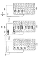
図5Aはモード選択処理を説明するための概念図である。図5Aに示されるように、最初はモード選択画面200が表示される。モード選択画面200には、「初期モード」の第1のアイコン210と、「文字入力モード」の第2のアイコン220と、「エアコンモード」の第3のアイコン230と、「テレビモード」の第4のアイコン240と、「照明スイッチモード」の第5のアイコン250が表示されており、各アイコン210、220、230、240、250が同一半径上に所定間隔おいて表示される。
FIG. 5A is a conceptual diagram for explaining mode selection processing. As shown in FIG. 5A, a
また、モード選択画面200には、各アイコン210、220、230、240、250の中から何れかを選択したことを示すモード選択カーソル260が表示されており、時間軸データP1〜P3の何れかが入力されると、入力された時間軸データP1〜P3の時間軸T1〜T3に応じたカーソル移動処理が行われる。
The
図5Bはモード選択制御処理を説明するためのフローチャートである。図5Bに示されるように、制御部60からの出力信号を受信した外部機器110のコントローラは、S11において、時間軸T1に相当する時間軸データP1が生成されたか否かをチェックする。S11において、時間軸T1に相当する時間軸データP1が生成された場合(YESの場合)、S12に進み、モード選択カーソル260が時計方向(右回り)に1ステップ移動する。例えば、初期モード210のモード選択カーソル260が一つ右隣の文字入力モードのアイコン220と一致する位置に移動する。さらに、時間軸T1の時間軸データP1が生成された場合、モード選択カーソル260が時計方向(右回り)に1ステップ移動して一つ右隣のエアコンモードのアイコン230と一致する位置に移動する。
FIG. 5B is a flowchart for explaining the mode selection control process. As shown in FIG. 5B, the controller of the
尚、モード選択カーソル260の位置を分かりやすくするため、モード選択カーソル260の囲まれた範囲内側を外側とは異なる色で表示しても良い。
In order to make the position of the
次のS13では、予め設定された所定時間(例えば、2〜3秒)が経過したか否かをチェックする。S13において、モード選択カーソル260が停止したまま所定時間が経過すると、S14に進み、当該カーソル停止位置と一致するアイコンの制御モードが選択(設定)される。
In next S13, it is checked whether or not a predetermined time (for example, 2 to 3 seconds) set in advance has elapsed. In S13, when a predetermined time elapses while the
また、上記S13において、所定時間が経過していない場合(NOの場合)、S15に進み、時間軸T3に相当する時間軸データP3が生成されたか否かをチェックする。S15において、時間軸T3に相当する時間軸データP3が生成された場合(YESの場合)、S14に進み、当該カーソル停止位置のアイコンの制御モードが選択(設定)される。この後は上記S11の処理に戻る。 In S13, if the predetermined time has not elapsed (NO), the process proceeds to S15, and it is checked whether or not time axis data P3 corresponding to the time axis T3 has been generated. When the time axis data P3 corresponding to the time axis T3 is generated in S15 (in the case of YES), the process proceeds to S14, and the control mode of the icon at the cursor stop position is selected (set). Thereafter, the process returns to S11.
また、上記S15において、時間軸T3に相当する時間軸データP3が生成されない場合(NOの場合)、上記S11の処理に戻り、S11以降の処理を実行する。また、S11において、時間軸T1に相当する時間軸データP1が生成されない場合(NOの場合)、S16に進み、時間軸T2に相当する時間軸データP2が生成されたか否かをチェックする。S16において、時間軸T2に相当する時間軸データP2が生成された場合(YESの場合)、S17に進み、モード選択カーソル260が時計方向(右回り)に2ステップ移動する。例えば、「初期モード」のアイコン210に位置するモード選択カーソル260が二つ右隣の「エアコンモード」のアイコン230と一致する位置に移動する。この後は、上記S13以降の処理を行う。
In S15, when the time axis data P3 corresponding to the time axis T3 is not generated (in the case of NO), the process returns to S11, and the processes after S11 are executed. In S11, when the time axis data P1 corresponding to the time axis T1 is not generated (NO), the process proceeds to S16, and it is checked whether or not the time axis data P2 corresponding to the time axis T2 is generated. When the time axis data P2 corresponding to the time axis T2 is generated in S16 (in the case of YES), the process proceeds to S17, and the
このように生体信号検出センサ20から生体信号E1〜E3が検出され、時間軸データP1〜P3が生成されることで、モード選択カーソル260がモニタ80に表示された各アイコン210、220、230、240、250のうち何れかのアイコンと一致する位置に移動し、「初期モード」、「文字入力モード」、「エアコンモード」、「テレビモード」、「照明スイッチモード」の中から操作者が希望する任意のモードを選択(設定)することが可能になる。
In this way, the biological signals E1 to E3 are detected from the biological
尚、制御部60において、時間軸T1に相当する時間軸データP1が生成された場合、モード選択カーソル260が時計方向(右回り)に1ステップずつ自動的に移動させ、時間軸T2の時間軸データP2が生成された場合、モード選択カーソル260を停止させ、時間軸T3の時間軸データP3が生成された場合、当該カーソル停止位置のアイコンの制御モードが設定されるように制御することも可能である。
When the time axis data P1 corresponding to the time axis T1 is generated in the
〔文字入力モードの制御処理方法〕
図6Aは文字入力モードの表示画面を説明するための概念図である。図6Aに示されるように、前述したモード選択カーソル260の移動により文字入力モードが選択されると、モニタ80に文字入力画面300が表示される。文字入力画面300には、ひらがなを選択できるように「あいうえお」を選択できる「あ行」310A、「かきくけこ」を選択できる「か行」320A、「さしすせそ」を選択できる「さ行」330A、「たちつてと」を選択できる「た行」340A、「なにぬねの」を選択できる「な行」350A、「はひふへほ」を選択できる「は行」360A、「まみむめも」を選択できる「ま行」370A、「やゆよ」を選択できる「や行」380A、「らりるれろ」を選択できる「ら行」390A、「わをん」を選択できる「わ行」400Aが表示される。
[Character input mode control processing method]
FIG. 6A is a conceptual diagram for explaining a display screen in a character input mode. As shown in FIG. 6A, when the character input mode is selected by moving the
さらに、文字入力画面300には、各行の中から任意の行を選択する第1の文字選択カーソル410と、上記50音のひらがなから任意の文字を選択するための第2の文字選択カーソル420が表示される。この文字選択カーソル410、420は、入力される時間軸データP1〜P3に応じてX方向(各文字列方向)またはY方向(文字行方向)に移動して任意の文字の座標位置へ移動する。
Further, the
例えば、第1の文字選択カーソル410が「あ行」310に停止している場合、「へ」の位置へカーソル移動させる操作方法について説明する。操作者100は、モニタ80に表示された文字入力画面300をみながら時間軸T1の時間軸データP1が出力されるように、神経信号を出力する。このとき、操作者100は、モニタ80に表示された文字入力画面300をみながらどの筋肉を動かすと神経信号が検出されるかを予め学習しており、そのとき検出された生体信号の波形パターンを制御部60に登録してある。尚、当該操作者が例えば筋萎縮性側索硬化症の場合には、十分な振幅(電圧)を有する筋電位信号が発せられなくても、筋紡錘からの微弱な生体信号を検出することができる。
For example, an operation method for moving the cursor to the “to” position when the first
図6Bは文字入力モードの制御方法を説明するためのフローチャートである。図6Bに示されるように、制御部60からの出力信号を受信した外部機器110のコントローラは、S21において、時間軸T1に相当する時間軸データP1が生成されたか否かをチェックする。S21において、時間軸T1に相当する時間軸データP1が生成された場合(YESの場合)、S22に進み、第1の文字選択カーソル410を横方向(X方向)に1ステップ移動させる。
FIG. 6B is a flowchart for explaining the control method of the character input mode. As shown in FIG. 6B, the controller of the
例えば、第1の文字選択カーソル410が文字入力画面300の「あ」の位置にある場合について説明する。生体信号検出センサ20から生体信号E1が検出されると、インターフェイス装置10の制御部60において、時間軸データP1が生成される。そして、時間軸データP1に対応する制御信号が入力されると、文字入力画面300に表示された第1の文字選択カーソル410が「あ行」310Aの位置からX方向に移動する。
For example, a case where the first
次のS23では、再度、時間軸T1に相当する時間軸データP1が生成されたか否かをチェックする。S23において、時間軸T1に相当する時間軸データP1が生成されない場合(NOの場合)、S22に戻り、第1の文字選択カーソル410を横方向(X方向)に1ステップ移動させる。これを6回繰り返すことにより、例えば、文字入力画面300の第1の文字選択カーソル410は、「は行」360Aの位置に移動する。
In the next S23, it is checked again whether or not the time axis data P1 corresponding to the time axis T1 has been generated. In S23, when the time axis data P1 corresponding to the time axis T1 is not generated (in the case of NO), the process returns to S22, and the first
また、上記S23において、時間軸T1に相当する時間軸データP1が生成された場合(YESの場合)、S24に進み、「あ」〜「わ」行の何れかが確定(設定)する。この後は上記S21の処理に戻る。 In S23, when the time axis data P1 corresponding to the time axis T1 is generated (in the case of YES), the process proceeds to S24, and any of the “a” to “wa” lines is determined (set). Thereafter, the process returns to S21.
次にS21において、時間軸T1に相当する時間軸データP1が生成されない場合(NOの場合)、S25に進み、時間軸T2に相当する時間軸データP2が生成されたか否かをチェックする。S25において、時間軸T2に相当する時間軸データP2が生成されない場合(NOの場合)、上記S21に戻り、S21、S25の処理を繰り返す待機状態となる。 Next, in S21, when the time axis data P1 corresponding to the time axis T1 is not generated (in the case of NO), the process proceeds to S25, and it is checked whether or not the time axis data P2 corresponding to the time axis T2 is generated. When the time axis data P2 corresponding to the time axis T2 is not generated in S25 (in the case of NO), the process returns to S21 and enters a standby state in which the processes of S21 and S25 are repeated.
また、上記S25において、時間軸T2に相当する時間軸データP2が生成された場合(YESの場合)、S26に進み、第2の文字選択カーソル420を縦方向(Y方向)に1ステップ移動させる。続いて、S27では、時間軸T1に相当する時間軸データP1が生成されたか否かをチェックする。S27において、時間軸T1に相当する時間軸データP1が生成されない場合(NOの場合)、上記S26に戻り、第2の文字選択カーソル420を縦方向(Y方向)に1ステップ移動させる。これを3回繰り返すと、文字入力画面300に表示された第2の文字選択カーソル420は、「へ」の位置に移動する。
If the time axis data P2 corresponding to the time axis T2 is generated in S25 (YES), the process proceeds to S26, and the second
そして、S27において、時間軸T1に相当する時間軸データP1が生成された場合(YESの場合)、S28に進み、「へ」の入力が確定(設定)する。この後は上記S21の処理に戻る。 In S27, when the time axis data P1 corresponding to the time axis T1 is generated (in the case of YES), the process proceeds to S28, and the input of “to” is confirmed (set). Thereafter, the process returns to S21.
このように生体信号検出センサ20から生体信号E1、E2が検出され、時間軸データP1、P2が生成されることで、任意の文字を入力することが可能になる。
As described above, the biological signals E1 and E2 are detected from the biological
〔エアコン設定モードの制御処理方法〕
図7Aはエアコン設定モードの表示画面を説明するための概念図である。図7Aに示されるように、前述したモード選択カーソル260の移動によりエアコンモードが選択されると、モニタ80にエアコン制御画面500が表示される。
[Control processing method of air conditioner setting mode]
FIG. 7A is a conceptual diagram for explaining a display screen of an air conditioner setting mode. As shown in FIG. 7A, when the air conditioner mode is selected by moving the
エアコン制御画面500の左側には、「冷房モード」のアイコン510と、「除湿モード」のアイコン520と、「暖房モード」のアイコン530と、「換気モード」のアイコン540とが表示される。また、エアコン制御画面500の上側には、「風量設定」のアイコン560Aと、「温度設定」のアイコン570Aと、「切タイマ設定」のアイコン580Aと、「入タイマ設定」のアイコン590Aと、「風向き設定」のアイコン600Aとが表示される。
On the left side of the air
各アイコンは、モード選択カーソル610、620、630を移動・停止させることで、任意のアイコンが選択、設定される。このアイコンの選択・設定操作は、前述した時間軸データP1〜P3の時間軸T1〜T3に基づいて行われる。
Each icon is selected and set by moving and stopping the
さらに、「風量設定」のアイコン560Aの下方には、風量を選択するための「弱」「中」「強」のアイコンが縦方向(Y方向)に並ぶ風量設定領域560Bが表示される。また、「温度設定」のアイコン570Aの下方には、「現設定」「マイナス1度〜5度」「プラス1〜5度」のアイコンが縦方向(Y方向)に並ぶ温度設定領域570Bが表示される。「切タイマ設定」のアイコン580Aに下方には、「30分、1時間〜10時間」のアイコンが縦方向(Y方向)に並ぶ切タイマ設定領域580Bが表示される。
Further, below the “air volume setting”
また、「入タイマ設定」のアイコン590Aの下方には、「30分、1時間〜10時間」の各アイコンが縦方向(Y方向)に並ぶ入タイマ設定領域590Bが表示される。また、「風向き設定」のアイコン600Aの下方には、「現設定、下へ1段階〜5段階、上へ1段階〜5段階」のアイコンが縦方向(Y方向)に並ぶ風向き設定領域600Bが表示される。
Also, below the “input timer setting”
さらに、エアコン制御画面500には、上記アイコン510〜540の中からメイン動作モードを選択する第1のモード選択カーソル610と、上記アイコン560A〜600Aの中からサブ動作モードを選択するための第2のモード選択カーソル620と、サブ動作モードの各制御データを選択するための第3のモード選択カーソル630とが表示される。このモード選択カーソル610、620、630は、入力される時間軸データP1〜P3に応じて任意の制御モードを選択する位置(X方向又はY方向の位置)へ移動する。
Further, the air
図7Bはエアコン設定モードの制御方法を説明するためのフローチャートである。図7Bに示されるように、制御部60からの出力信号を受信した外部機器110のコントローラは、S31において、時間軸T1に相当する時間軸データP1が生成されたか否かをチェックする。S31において、時間軸T1に相当する時間軸データP1が生成された場合(YESの場合)、S32に進み、第1のモード選択カーソル610を縦方向(Y方向)に1ステップ移動させる。例えば、メイン動作モードである「冷房モード」のアイコン510、「除湿モード」のアイコン520、「暖房モード」のアイコン530、「換気モード」のアイコン540の何れかを選択できる。
FIG. 7B is a flowchart for explaining a control method of the air conditioner setting mode. As illustrated in FIG. 7B, the controller of the
次のS33では、再度、時間軸T1に相当する時間軸データP1が生成されたか否かをチェックする。S33において、時間軸T1に相当する時間軸データP1が生成されない場合(NOの場合)、S32に戻り、第1のモード選択カーソル610を縦方向(下方向)に1ステップ移動させる。これを1〜4回繰り返すことにより、第1のモード選択カーソル610は、メイン動作モードである「冷房モード」、「除湿モード」、「暖房モード」、「換気モード」のアイコン510、520、530、540の何れかの位置に移動する。
In next S33, it is checked again whether or not the time axis data P1 corresponding to the time axis T1 has been generated. If the time axis data P1 corresponding to the time axis T1 is not generated in S33 (NO), the process returns to S32, and the first
また、時間軸T1に相当する時間軸データP1が生成された場合(YESの場合)、S34に進み、「冷房モード」、「除湿モード」、「暖房モード」、「換気モード」の中から第1のモード選択カーソル610のカーソル停止位置と一致するメイン動作モードが選択され、「冷房モード」、「除湿モード」、「暖房モード」、「換気モード」の何れかのモードに確定(設定)する。この後は上記S31の処理に戻る。
Further, when the time axis data P1 corresponding to the time axis T1 is generated (in the case of YES), the process proceeds to S34, and the “cooling mode”, “dehumidification mode”, “heating mode”, and “ventilation mode” are selected. The main operation mode that coincides with the cursor stop position of the first
上記S31において、時間軸T1に相当する時間軸データP1が生成されない場合(NOの場合)、S35に進み、時間軸T2に相当する時間軸データP2が生成されたか否かをチェックする。上記S35において、時間軸T2に相当する時間軸データP2が生成された場合(YESの場合)、S36に進み、第2のモード選択カーソル620を横方向(X方向)に1ステップ移動させる。続いて、S37では、時間軸T1に相当する時間軸データP1が生成されたか否かをチェックする。S37において、時間軸T1に相当する時間軸データP1が生成されない場合(NOの場合)、上記S36に戻り、第2のモード選択カーソル620を横方向(X方向)に1ステップ移動させる。
In S31, when the time axis data P1 corresponding to the time axis T1 is not generated (in the case of NO), the process proceeds to S35, and it is checked whether or not the time axis data P2 corresponding to the time axis T2 is generated. When the time axis data P2 corresponding to the time axis T2 is generated in S35 (YES), the process proceeds to S36, and the second
これを1〜5回繰り返すと、文字入力画面300に表示された第2のモード選択カーソル620は、「風量設定」のアイコン560A、「温度設定」のアイコン570A、「切タイマ設定」のアイコン580A、「入タイマ設定」のアイコン590A、「風向き設定」のアイコン600Aの何れかの位置に移動する。
When this is repeated 1 to 5 times, the second
上記S37において、時間軸T1に相当する時間軸データP1が生成された場合(YESの場合)、S38に進み、「風量設定」、「温度設定」、「切タイマ設定」、「入タイマ設定」、「風向き設定」の中から第2のモード選択カーソル620のカーソル停止位置と一致する任意のサブ動作モードが確定(設定)する。この後は上記S31の処理に戻る。
If the time axis data P1 corresponding to the time axis T1 is generated in S37 (YES), the process proceeds to S38, and “air volume setting”, “temperature setting”, “off timer setting”, “on timer setting”. In the “wind direction setting”, an arbitrary sub operation mode that matches the cursor stop position of the second
また、上記S35において、時間軸T2に相当する時間軸データP2が生成されない場合(NOの場合)、S39に進み、時間軸T3に相当する時間軸データP3が生成されたか否かをチェックする。S39において、時間軸T3に相当する時間軸データP3が生成されない場合(NOの場合)、上記S31に戻り、S31、S35、S39の処理を繰り返す待機状態となる。 In S35, when the time axis data P2 corresponding to the time axis T2 is not generated (in the case of NO), the process proceeds to S39, and it is checked whether or not the time axis data P3 corresponding to the time axis T3 is generated. In S39, when the time axis data P3 corresponding to the time axis T3 is not generated (in the case of NO), the process returns to S31 and enters a standby state in which the processes of S31, S35, and S39 are repeated.
上記S39において、時間軸T3に相当する時間軸データP3が生成された場合(YESの場合)、S40に進み、第3のモード選択カーソル630を縦方向(Y方向)に1ステップ移動させる。続いて、S41では、時間軸T1に相当する時間軸データP1が生成されたか否かをチェックする。S41において、時間軸T1に相当する時間軸データP1が生成されない場合(NOの場合)、上記S40に戻り、第3のモード選択カーソル630を縦方向(Y方向)に1ステップ移動させる。
In S39, when the time axis data P3 corresponding to the time axis T3 is generated (in the case of YES), the process proceeds to S40, and the third
上記S41において、時間軸T1に相当する時間軸データP1が生成された場合(YESの場合)、S42に進み、「風量設定」、「温度設定」、「切タイマ設定」、「入タイマ設定」、「風向き設定」の中から選択された任意のサブ動作モードの制御量(例えば、温度をマイナス3度)が確定(設定)する。この後は上記S31の処理に戻る。 When the time axis data P1 corresponding to the time axis T1 is generated in the above S41 (in the case of YES), the process proceeds to S42 and “air volume setting”, “temperature setting”, “off timer setting”, “on timer setting”. , The control amount (for example, minus 3 degrees of temperature) in an arbitrary sub operation mode selected from “wind direction setting” is fixed (set). Thereafter, the process returns to S31.
このように生体信号検出センサ20から生体信号E1〜E3が検出され、時間軸データP1〜P3が生成されることで、エアコンの任意のモードあるいは温度や湿度、風向きなどの調整データ(制御信号)を入力することが可能になる。
As described above, the biological signals E1 to E3 are detected from the biological
〔テレビ操作モードの制御処理方法〕
図8Aはテレビ操作モードの場合の制御処理方法を説明するための概念図である。図8Aに示されるように、前述したモード選択カーソル260の移動によりテレビモードが選択されると、モニタ80にテレビ制御画面700が表示される。
[Control processing method for TV operation mode]
FIG. 8A is a conceptual diagram for explaining a control processing method in the television operation mode. As shown in FIG. 8A, when the television mode is selected by the above-described movement of the
テレビ制御画面700には、「チャンネル切替モード」のアイコン710Aと、「音量調整モード」のアイコン720Aと、「予約モード」のアイコン730Aとが表示される。さらに、テレビ制御画面700には、「チャンネル切替モード」の各チャンネル番号1〜12の表示領域710Bと、「音量調整モード」の音量調整表示領域720Bと、「予約モード」の番組予約表示領域730Bとが表示される。
On the
また、テレビ制御画面700には、「チャンネル切替モード」のアイコン710A、「音量調整モード」のアイコン720A、「予約モード」のアイコン730Aの中から何れかのメイン動作モードを選択するための第1のモード選択カーソル810と、各モード710B、720B、730Bの中に表示されるサブ動作モードの制御データを選択する第2のモード選択カーソル820とが表示される。このモード選択カーソル810、820は、入力される時間軸データP1、P2に応じて任意の制御モードを選択する位置へ移動する。
The
図8Bはテレビ操作モードの制御方法を説明するためのフローチャートである。図8Bに示されるように、制御部60からの出力信号を受信した外部機器110のコントローラは、S51において、時間軸T1に相当する時間軸データP1が生成されたか否かをチェックする。S51において、時間軸T1に相当する時間軸データP1が生成された場合(YESの場合)、S22に進み、第1のモード選択カーソル810を横方向(X方向)に1ステップ移動させる。
FIG. 8B is a flowchart for explaining a control method of the television operation mode. As illustrated in FIG. 8B, the controller of the
例えば、第1のモード選択カーソル810が「チャンネル切替モード」のアイコン710Aの位置にある場合について説明する。生体信号検出センサ20から生体信号E1が検出されると、インターフェイス装置10の制御部60において、時間軸データP1が生成される。そして、時間軸データP1が入力されると、テレビ制御画面700に表示された第1のモード選択カーソル810がアイコン710Aの位置から右隣の「音量調整モード」のアイコン720Aの位置に移動する。
For example, the case where the first
次のS53では、再度、時間軸T1に相当する時間軸データP1が生成されたか否かをチェックする。S53において、時間軸T1に相当する時間軸データP1が生成されない場合(NOの場合)、S52に戻り、第1のモード選択カーソル810を横方向(X方向)に1ステップ移動させる。これを2回繰り返すことにより、第1のモード選択カーソル810は、「音量調整モード」のアイコン720A、「予約モード」のアイコン730Aの位置に移動する。
In next S53, it is checked again whether or not the time axis data P1 corresponding to the time axis T1 has been generated. In S53, when the time axis data P1 corresponding to the time axis T1 is not generated (in the case of NO), the process returns to S52, and the first
また、上記S53において、時間軸T1に相当する時間軸データP1が生成された場合(YESの場合)、S54に進み、「チャンネル切替モード」、「音量調整モード」、「予約モード」の何れかが確定(設定)する。この後は上記S51の処理に戻る。 In S53, when the time axis data P1 corresponding to the time axis T1 is generated (in the case of YES), the process proceeds to S54, and any one of “channel switching mode”, “volume adjustment mode”, and “reservation mode” is selected. Is fixed (set). Thereafter, the process returns to S51.
次に上記S51において、時間軸T1に相当する時間軸データP1が生成されない場合(NOの場合)、S55に進み、時間軸T2に相当する時間軸データP2が生成されたか否かをチェックする。S55において、時間軸T2に相当する時間軸データP2が生成されない場合(NOの場合)、上記S51に戻り、S51、S55の処理を繰り返す待機状態となる。 Next, in S51, when the time axis data P1 corresponding to the time axis T1 is not generated (NO), the process proceeds to S55, and it is checked whether or not the time axis data P2 corresponding to the time axis T2 is generated. In S55, when the time axis data P2 corresponding to the time axis T2 is not generated (in the case of NO), the process returns to S51 and enters a standby state in which the processes of S51 and S55 are repeated.
また、上記S55において、時間軸T2に相当する時間軸データP2が生成された場合(YESの場合)、S56に進み、第2のモード選択カーソル820を縦方向(Y方向)に1ステップ移動させる。続いて、S57では、時間軸T1に相当する時間軸データP1が生成されたか否かをチェックする。S57において、時間軸T1に相当する時間軸データP1が生成されない場合(NOの場合)、上記S56に戻り、第2のモード選択カーソル820を縦方向(Y方向)に1ステップ移動させる。これを5回繰り返すと、例えばテレビ制御画面700に表示された第2のモード選択カーソル820は、「音量調整モード」の「1目盛」の位置から「5目盛」の位置に移動する。
If the time axis data P2 corresponding to the time axis T2 is generated in S55 (YES), the process proceeds to S56, and the second
そして、S57において、時間軸T1に相当する時間軸データP1が生成された場合(YESの場合)、S58に進み、「音量調整モード」の「5目盛」又は「消音」の入力が確定(設定)する。この後は上記S51の処理に戻る。 If the time axis data P1 corresponding to the time axis T1 is generated in S57 (in the case of YES), the process proceeds to S58, and the input of “5 scale” or “mute” in “volume adjustment mode” is confirmed (set) ) Thereafter, the process returns to S51.
このように生体信号検出センサ20から生体信号E1、E2が検出され、時間軸データP1、P2が生成されることで、テレビのチャンネル、音量、番組の予約を設定することが可能になる。
In this way, the biological signals E1 and E2 are detected from the biological
〔照明スイッチ切替操作モードの制御処理方法〕
図9Aは照明スイッチの切替え操作の制御処理方法を説明するための概念図である。図9Aに示されるように、前述したモード選択カーソル260の移動により照明スイッチモードが選択されると、モニタ80に照明スイッチ制御画面900が表示される。
[Control processing method of lighting switch switching operation mode]
FIG. 9A is a conceptual diagram for explaining a control processing method of a lighting switch switching operation. As shown in FIG. 9A, when the illumination switch mode is selected by moving the
照明スイッチ制御画面900には、「消灯モード」のアイコン910と、「半灯モード(複数の照明灯の半分を点灯)」のアイコン920と、「全灯モード(複数の照明灯を全て点灯)」のアイコン930と、「半灯モード(全灯の半分の照度)」のアイコン940と、「豆灯モード(小電球点灯)」のアイコン950とが同一半径上に配置されて表示される。また、照明スイッチ制御画面900には、「消灯モード」のアイコン910、「半灯モード」のアイコン920、「全灯モード」のアイコン930、「半灯モード」のアイコン940、「豆灯モード」のアイコン950の何れかを選択するためのモード選択カーソル960が表示される。このモード選択カーソル960は、入力される時間軸データP1〜P3に応じて任意の制御モードを選択する位置へ移動する。
On the lighting
図9Bは照明スイッチ切替操作モードの制御方法を説明するためのフローチャートである。図9Bに示されるように、制御部60からの出力信号を受信した外部機器110のコントローラは、S61において、時間軸T1に相当する時間軸データP1が生成されたか否かをチェックする。S61において、時間軸T1に相当する時間軸データP1が生成された場合(YESの場合)、S62に進み、モード選択カーソル960が時計方向(右回り)に1ステップ移動する。例えば、モード選択カーソル960が「消灯」のアイコン910にある場合、時計方向(右回り)に1ステップ移動して一つ右隣の「半灯モード」のアイコン920と一致する位置に移動する。さらに、時間軸T1の時間軸データP1が生成された場合、モード選択カーソル960が時計方向(右回り)に1ステップ移動して一つ右隣の「全灯モード」のアイコン930と一致する位置に移動する。
FIG. 9B is a flowchart for explaining a control method of the illumination switch switching operation mode. As illustrated in FIG. 9B, the controller of the
次のS63では、予め設定された所定時間(例えば、2〜3秒)が経過したか否かをチェックする。S63において、モード選択カーソル960が停止したまま所定時間が経過すると、S64に進み、「消灯モード」、「半灯モード」、「全灯モード」、「半灯モード」、「豆灯モード」のうち当該カーソル停止位置と一致する制御モードが選択(設定)される。
In the next S63, it is checked whether or not a predetermined time (for example, 2 to 3 seconds) set in advance has elapsed. In S63, when a predetermined time elapses while the
また、上記S63において、所定時間が経過していない場合(NOの場合)、S65に進み、時間軸T3に相当する時間軸データP3が生成されたか否かをチェックする。S65において、時間軸T3に相当する時間軸データP3が生成された場合(YESの場合)、S64に進み、当該カーソル停止位置のアイコンの制御モードが設定される。この後は上記S61の処理に戻る。 In S63, if the predetermined time has not elapsed (NO), the process proceeds to S65, and it is checked whether or not the time axis data P3 corresponding to the time axis T3 has been generated. When the time axis data P3 corresponding to the time axis T3 is generated in S65 (YES), the process proceeds to S64, and the control mode of the icon at the cursor stop position is set. Thereafter, the process returns to S61.
また、上記S65において、時間軸T3に相当する時間軸データP3が生成されない場合(NOの場合)、上記S61の処理に戻り、S61以降の処理を実行する。また、S61において、時間軸T1に相当する時間軸データP1が生成されない場合(NOの場合)、S66に進み、時間軸T2に相当する時間軸データP2が生成されたか否かをチェックする。S66において、時間軸T2に相当する時間軸データP2が生成された場合(YESの場合)、S67に進み、モード選択カーソル260が時計方向(右回り)に2ステップ移動する。例えば、「消灯モード」のアイコン910に位置するモード選択カーソル960が二つ右隣の「全灯コンモード」のアイコン930と一致する位置に移動する。この後は、上記S63以降の処理を行う。
In S65, when the time axis data P3 corresponding to the time axis T3 is not generated (in the case of NO), the process returns to S61, and the processes after S61 are executed. In S61, when the time axis data P1 corresponding to the time axis T1 is not generated (in the case of NO), the process proceeds to S66, and it is checked whether or not the time axis data P2 corresponding to the time axis T2 is generated. If the time axis data P2 corresponding to the time axis T2 is generated in S66 (in the case of YES), the process proceeds to S67, and the
尚、制御部60からの出力信号を受信した外部機器110のコントローラにおいて、時間軸T1に相当する時間軸データP1が生成された場合、モード選択カーソル960が時計方向(右回り)に1ステップずつ自動的に移動させ、時間軸T2の時間軸データP2が生成された場合、モード選択カーソル960を停止させ、時間軸T3の時間軸データP3が生成された場合、当該カーソル停止位置のアイコンの制御モードが設定されるように制御することも可能である。
When the time axis data P1 corresponding to the time axis T1 is generated in the controller of the
上記実施例では、外部機器として文字入力装置、エアコンのコントローラ、テレビのリモコン、照明の切替えスイッチなどを例示したが、これに限らず、これ以外の装置にも適用できるのは、勿論である。 In the above-described embodiment, a character input device, an air conditioner controller, a television remote controller, a lighting changeover switch, and the like are illustrated as external devices. However, the present invention is not limited to this and can be applied to other devices.
また、上記実施例で説明したもの以外の外部機器としては、例えば車椅子のロボットハンドを取り付けて車椅子に座った操作者の生体信号に基づいてロボットハンドを動作させることも可能である。尚、ロボットハンドとしては、肩関節、肘関節、手首関節に相当する複数の関節を有し、人間の手のように複数の指が駆動可能に設けられたものでも良い。また、ロボットハンドの動作としては、皿や茶碗などの食器を持ち上げて移動させたり、あるいは各指を動作させてピアノの鍵盤を押して曲を演奏したり、あるいは車椅子の進行方向のドアを開けたりと多目的に動作させることも可能である。 In addition, as an external device other than the one described in the above embodiment, for example, a robot hand can be attached and a robot hand can be operated based on a biological signal of an operator sitting on the wheelchair. The robot hand may have a plurality of joints corresponding to a shoulder joint, an elbow joint, and a wrist joint, and may be provided with a plurality of fingers that can be driven like a human hand. The robot hand can be moved by lifting dishes such as dishes and teacups, or by moving each finger to play a song by pressing a piano keyboard, or opening the door in the direction of the wheelchair. It can also be operated for multiple purposes.
10、10A インターフェイス装置
20 生体信号検出センサ
30 差動増幅器
40 増幅・フィルタ回路
50 ADコンバータ
60 制御部
62 時間軸データ変換手段
64 制御信号変換手段
70 送信回路
80 モニタ
82 受信回路
100 操作者
110A〜110C 外部機器
112a、112b、112a'、112b'、112a''、112b'' 入力端子
200 モード選択画面
260、550、960 モード選択カーソル
300 文字入力画面
410 第1の文字選択カーソル
420 第2の文字選択カーソル
500 エアコン制御画面
610 第1のモード選択カーソル
620 第2のモード選択カーソル
630 第3のモード選択カーソル
700 テレビ制御画面
810 第1のモード選択カーソル
820 第2のモード選択カーソル
900 照明スイッチ制御画面
10,
Claims (6)
前記複数の信号検出センサより得られた各神経信号の差分に基づく電位を所定電圧値に増幅して、時間軸上においてゼロ電位から+側に立ち上り、最大値に達すると、−側に低下した後、再び+側に推移しながらゼロ電位に戻る傾向を示す生体信号を出力する差動増幅器と、
前記差動増幅器により増幅された前記生体信号をアナログ信号のまま所定周波数範囲のみ通過させて増幅して出力する増幅・フィルタ回路と、
前記増幅・フィルタ回路により増幅されたアナログ信号の前記生体信号をデジタル変換するA/D変換器と、
デジタル化された前記生体信号の電位と予め設定された+側の閾値とを比較し、当該閾値以上になった時点の立ち上がりエッジの一定時間内の連続数が所定数を越えた時点を始点とし、かつ、当該始点から所定時間の経過時点を終点とする矩形波信号を出力する出力信号生成手段と、
前記矩形波信号を、当該矩形波信号の時間軸長さに応じた操作内容が予め割り当てられている外部機器に送信する送信手段と
を備え、前記出力信号生成手段は、前記矩形波信号の前記始点を常時検出し、最初の始点から前記所定時間の経過時までに次の始点を検出した場合には、当該検出された次の始点を基準に前記所定時間の経過時まで終点を延長することにより、前記矩形波信号の時間軸長さを変更する
ことを特徴とするインターフェイス装置。 Attached to the operator of the different parts of the skin, a plurality of signal detection sensor for detecting a neural signal generated from the nerve cells of the operator, respectively,
The potential based on the difference between the neural signals obtained from the plurality of signal detection sensors is amplified to a predetermined voltage value , rises from the zero potential to the + side on the time axis, and decreases to the − side when the maximum value is reached. after a differential amplifier outputting a biological signal indicating a tendency to return to the zero potential while remained again positive side,
An amplifier-filter circuit for outputting the biological signal by Ri amplification in the differential amplifier circuit by amplifying by passing only a predetermined frequency range remains an analog signal,
An A / D converter for digitally converting the biological signal of the analog signal amplified by the amplification / filter circuit;
The digitized potential of the biological signal is compared with a preset positive threshold, and the starting point is the time when the number of consecutive rising edges within a certain time exceeds the predetermined value. And an output signal generating means for outputting a rectangular wave signal whose end point is an elapse time of a predetermined time from the start point ;
Transmitting means for transmitting the rectangular wave signal to an external device preliminarily assigned with the operation content according to the time axis length of the rectangular wave signal , and the output signal generating means includes the output of the rectangular wave signal. The start point is always detected, and when the next start point is detected from the first start point until the elapse of the predetermined time, the end point is extended to the elapse of the predetermined time based on the detected next start point. To change the time axis length of the rectangular wave signal .
ことを特徴とする請求項1に記載のインターフェイス装置。 The output signal generation means sets a length corresponding to a difference in individual characteristics of the operator as the predetermined time for determining a length of a time axis of the rectangular wave signal. 2. The interface device according to 1.
ことを特徴とする請求項1または2に記載のインターフェイス装置。 The said output signal generation means produces | generates the said rectangular wave signal only based on the said biomedical signal linked | linked with the said operator's intention by making elements other than the said threshold value into a dead zone. Interface equipment.
前記第1の過程より得られた各神経信号の差分に基づく電位を所定電圧値に増幅して、時間軸上においてゼロ電位から+側に立ち上がり、最大値に達すると、−側に低下した後、再び+側に推移しながらゼロ電位に戻る傾向を示す生体信号を出力する第2の過程と、
前記第2の過程により増幅された前記生体信号をアナログ信号のまま所定周波数範囲のみ通過させて増幅して出力する第3の過程と、
前記第3の過程により増幅されたアナログ信号の前記生体信号をデジタル変換する第4の過程と、
前記第4の過程によりデジタル化された前記生体信号の電位と予め設定された+側の閾値とを比較し、当該閾値以上になった時点の立ち上がりエッジの一定時間内の連続数が所定数を越えた時点を始点とし、かつ、当該始点から所定時間の経過時点を終点とする矩形波信号を出力する第5の過程と、
前記矩形波信号を、当該矩形波信号の時間軸長さに応じた操作内容が予め割り当てられている外部機器に送信する第6の過程と、
を行い、前記第5の過程では、前記矩形波信号の前記始点を常時検出し、最初の始点から前記所定時間の経過時までに次の始点を検出した場合には、当該検出された次の始点を基準に前記所定時間の経過時まで終点を延長することにより、前記矩形波信号の時間軸長さを変更する
ことを特徴とするインターフェイス装置の制御方法。 In the operator of the different parts of the skin, a first step of detecting a neural signal generated from the nerve cells of the operator, respectively,
After amplifying the potential based on the difference between each neural signal obtained in the first step to a predetermined voltage value , rising from zero potential to the + side on the time axis, and decreasing to the − side when reaching the maximum value A second process of outputting a biological signal indicating a tendency to return to zero potential while transitioning to the + side again ;
A third step of outputting the second of the biological signal that is a width increase of Ri by the process amplifies by passing only a predetermined frequency range remains an analog signal,
A fourth step of digitally converting the biological signal of the analog signal amplified by the third step ;
The potential of the biological signal digitized by the fourth process is compared with a preset positive threshold value, and the number of consecutive rising edges within a predetermined time when the threshold value becomes equal to or higher than the threshold value is a predetermined number. A fifth step of outputting a rectangular wave signal having a time point exceeding the start point and an end point after a lapse of a predetermined time from the start point ;
A sixth step of transmitting the rectangular wave signal to an external device to which an operation content corresponding to the time axis length of the rectangular wave signal is assigned in advance ;
Gastric lines, in the fifth step, and detecting the start point of the rectangular wave signal at all times, when detection of the next start point to the first starting point until the lapse of the predetermined time, which is the detected next A method for controlling an interface device , comprising: changing a time axis length of the rectangular wave signal by extending an end point until the elapse of the predetermined time with respect to a start point of the signal .
ことを特徴とする請求項4に記載のインターフェイス装置の制御方法。 In the fifth step, a length corresponding to the difference in individual characteristics of the operator is set as the predetermined time for determining the length of the time axis of the rectangular wave signal.
The method of controlling an interface device according to claim 4 .
ことを特徴とする請求項4または5に記載のインターフェイス装置の制御方法。 6. The method of controlling an interface device according to claim 4, wherein the interface device is controlled.
Priority Applications (1)
| Application Number | Priority Date | Filing Date | Title |
|---|---|---|---|
| JP2012257387A JP6084823B2 (en) | 2012-11-26 | 2012-11-26 | Interface device and control method thereof |
Applications Claiming Priority (1)
| Application Number | Priority Date | Filing Date | Title |
|---|---|---|---|
| JP2012257387A JP6084823B2 (en) | 2012-11-26 | 2012-11-26 | Interface device and control method thereof |
Publications (2)
| Publication Number | Publication Date |
|---|---|
| JP2014106601A JP2014106601A (en) | 2014-06-09 |
| JP6084823B2 true JP6084823B2 (en) | 2017-02-22 |
Family
ID=51028060
Family Applications (1)
| Application Number | Title | Priority Date | Filing Date |
|---|---|---|---|
| JP2012257387A Active JP6084823B2 (en) | 2012-11-26 | 2012-11-26 | Interface device and control method thereof |
Country Status (1)
| Country | Link |
|---|---|
| JP (1) | JP6084823B2 (en) |
Families Citing this family (1)
| Publication number | Priority date | Publication date | Assignee | Title |
|---|---|---|---|---|
| WO2019111471A1 (en) * | 2017-12-08 | 2019-06-13 | ソニー株式会社 | Information processing device, method for controlling same, and recording medium |
Family Cites Families (6)
| Publication number | Priority date | Publication date | Assignee | Title |
|---|---|---|---|---|
| JPS54121025A (en) * | 1978-03-13 | 1979-09-19 | Agency Of Ind Science & Technol | Signal generating device for machine operation |
| JP4661115B2 (en) * | 2004-07-15 | 2011-03-30 | ソニー株式会社 | Signal processing apparatus, signal processing method, and mechanical apparatus |
| JP2006051343A (en) * | 2004-07-16 | 2006-02-23 | Semiconductor Energy Lab Co Ltd | Biological signal processor, radio memory, processing system for biological signal, and controlling system for controlled apparatus |
| US20090281448A1 (en) * | 2008-05-10 | 2009-11-12 | Neural Signals, Inc. | Wireless Skin Surface Potential Sensing System and Method |
| JP5283065B2 (en) * | 2008-08-26 | 2013-09-04 | 学校法人慶應義塾 | Motion-related potential signal detection system |
| KR101226169B1 (en) * | 2008-09-10 | 2013-01-24 | 고쿠리쯔 다이가쿠 호징 츠쿠바 다이가쿠 | Wearing tool for measuring biological signal, and wearing-type motion assisting device |
-
2012
- 2012-11-26 JP JP2012257387A patent/JP6084823B2/en active Active
Also Published As
| Publication number | Publication date |
|---|---|
| JP2014106601A (en) | 2014-06-09 |
Similar Documents
| Publication | Publication Date | Title |
|---|---|---|
| Stefanov et al. | The smart house for older persons and persons with physical disabilities: structure, technology arrangements, and perspectives | |
| JP7149492B2 (en) | EMG-assisted communication device with context-sensitive user interface | |
| Valbuena et al. | Brain-computer interface for high-level control of rehabilitation robotic systems | |
| US11093038B2 (en) | Systems and methods for generic control using a neural signal | |
| JP2024012497A (en) | Communication methods and systems | |
| US20220113799A1 (en) | Multiple switching electromyography (emg) assistive communications device | |
| KR101955941B1 (en) | SYSTEM AND METHOD FOR PROVIDING MENTAL CARE BASED ON IoT USING BRAIN WAVES | |
| CN105411580A (en) | Brain control wheelchair system based on touch and auditory evoked potential | |
| Lo et al. | Novel non-contact control system for medical healthcare of disabled patients | |
| JP6084823B2 (en) | Interface device and control method thereof | |
| US8894718B2 (en) | System for remote management in ambient intelligence environments using electromyographic signals | |
| KR102386359B1 (en) | System and method for controlling exoskeleton robot using brain waves according to motion imagination | |
| Iliev et al. | Assisted living systems for elderly and disabled people: a short review | |
| KR102126801B1 (en) | Timing feedback system based on multi-sensor with adjusting intensity of exercise | |
| Contreras-Castañeda et al. | Smart home: Multimodal interaction for control of home devices | |
| JPH10262942A (en) | Satisfaction feeling measuring system and feedback device | |
| Cincotti et al. | Brain-operated assistive devices: the ASPICE project | |
| Hassan et al. | EEG Signal Based Cognitive System for Controlling Home Appliances and Generating Speech Command | |
| KR101214544B1 (en) | System and method for controlling input using activeness detecting device | |
| Madhavi et al. | Sustainable practices for semi-paralysed people using gesture-link paralysis glove | |
| KR101727183B1 (en) | Home care system using brain wave | |
| Cincotti et al. | Non-invasive brain-computer interface system to operate assistive devices | |
| KR20200130006A (en) | Health care system and method using lighting device based on IoT | |
| Kader et al. | Wireless Need Sharing & Home Appliance Control For Quadriplegic Patients Using Head Motion Detection Via 3-Axis Accelerometer | |
| EP3193239A1 (en) | Methods and systems for augmentative and alternative communication |
Legal Events
| Date | Code | Title | Description |
|---|---|---|---|
| A621 | Written request for application examination |
Free format text: JAPANESE INTERMEDIATE CODE: A621 Effective date: 20151125 |
|
| A521 | Request for written amendment filed |
Free format text: JAPANESE INTERMEDIATE CODE: A523 Effective date: 20151215 |
|
| A521 | Request for written amendment filed |
Free format text: JAPANESE INTERMEDIATE CODE: A821 Effective date: 20151215 |
|
| A977 | Report on retrieval |
Free format text: JAPANESE INTERMEDIATE CODE: A971007 Effective date: 20160826 |
|
| A131 | Notification of reasons for refusal |
Free format text: JAPANESE INTERMEDIATE CODE: A131 Effective date: 20160830 |
|
| A521 | Request for written amendment filed |
Free format text: JAPANESE INTERMEDIATE CODE: A523 Effective date: 20161028 |
|
| TRDD | Decision of grant or rejection written | ||
| A01 | Written decision to grant a patent or to grant a registration (utility model) |
Free format text: JAPANESE INTERMEDIATE CODE: A01 Effective date: 20170104 |
|
| A61 | First payment of annual fees (during grant procedure) |
Free format text: JAPANESE INTERMEDIATE CODE: A61 Effective date: 20170126 |
|
| R150 | Certificate of patent or registration of utility model |
Ref document number: 6084823 Country of ref document: JP Free format text: JAPANESE INTERMEDIATE CODE: R150 |
|
| R250 | Receipt of annual fees |
Free format text: JAPANESE INTERMEDIATE CODE: R250 |
|
| R250 | Receipt of annual fees |
Free format text: JAPANESE INTERMEDIATE CODE: R250 |