JP6083946B2 - Image processing apparatus and image processing apparatus control method - Google Patents
Image processing apparatus and image processing apparatus control method Download PDFInfo
- Publication number
- JP6083946B2 JP6083946B2 JP2012089698A JP2012089698A JP6083946B2 JP 6083946 B2 JP6083946 B2 JP 6083946B2 JP 2012089698 A JP2012089698 A JP 2012089698A JP 2012089698 A JP2012089698 A JP 2012089698A JP 6083946 B2 JP6083946 B2 JP 6083946B2
- Authority
- JP
- Japan
- Prior art keywords
- interpolation
- signal
- image
- peaking
- image signal
- Prior art date
- Legal status (The legal status is an assumption and is not a legal conclusion. Google has not performed a legal analysis and makes no representation as to the accuracy of the status listed.)
- Expired - Fee Related
Links
- 238000000034 method Methods 0.000 title claims description 68
- 230000008569 process Effects 0.000 claims description 55
- 230000007274 generation of a signal involved in cell-cell signaling Effects 0.000 claims description 15
- 230000003287 optical effect Effects 0.000 claims description 7
- 238000003860 storage Methods 0.000 claims description 7
- 230000008859 change Effects 0.000 claims description 6
- 238000003384 imaging method Methods 0.000 claims description 6
- 230000006870 function Effects 0.000 description 19
- 238000010586 diagram Methods 0.000 description 6
- 238000006243 chemical reaction Methods 0.000 description 3
- 238000004519 manufacturing process Methods 0.000 description 3
- 238000009826 distribution Methods 0.000 description 2
- 230000009467 reduction Effects 0.000 description 2
- FFBHFFJDDLITSX-UHFFFAOYSA-N benzyl N-[2-hydroxy-4-(3-oxomorpholin-4-yl)phenyl]carbamate Chemical compound OC1=C(NC(=O)OCC2=CC=CC=C2)C=CC(=C1)N1CCOCC1=O FFBHFFJDDLITSX-UHFFFAOYSA-N 0.000 description 1
- 239000000872 buffer Substances 0.000 description 1
- 238000012790 confirmation Methods 0.000 description 1
- 230000000694 effects Effects 0.000 description 1
- ORQBXQOJMQIAOY-UHFFFAOYSA-N nobelium Chemical compound [No] ORQBXQOJMQIAOY-UHFFFAOYSA-N 0.000 description 1
- 230000002093 peripheral effect Effects 0.000 description 1
- 230000004044 response Effects 0.000 description 1
Images


Landscapes
- Image Processing (AREA)
- Editing Of Facsimile Originals (AREA)
- Studio Devices (AREA)
Description
本発明はフォーカス調整用にエッジ強調のためのピーキングアシスト機能を行う画像処理装置及び画像処理装置の制御方法に関するものである。 The present invention relates to an image processing apparatus that performs a peaking assist function for edge enhancement for focus adjustment, and a control method for the image processing apparatus.
従来ビデオカメラではフォーカス調整を容易にするため、画像にピーキング信号を付加するフォーカスアシスト機能が備えられている。ピーキング信号とは映像信号から高周波成分を抽出し、増幅することで生成される信号である。特許文献1では、ピーキング信号を映像信号に加算しビューファインダもしくは出力モニタに表示することで映像中の輪郭部分が強調して表示され、ユーザに合焦の程度を視覚的に知らせることによりフォーカス調整を容易に行うことを可能としている。 Conventional video cameras have a focus assist function for adding a peaking signal to an image in order to facilitate focus adjustment. The peaking signal is a signal generated by extracting and amplifying a high frequency component from the video signal. In Patent Document 1, a peaking signal is added to a video signal and displayed on a viewfinder or an output monitor so that a contour portion in the video is highlighted and the focus adjustment is performed by visually informing the user of the degree of focus. Can be easily performed.
しかしながら、特許文献1では、ピーキング信号生成部の後に表示デバイスのサイズに応じて拡大縮小を行う構成をとっているため、フォーカスアシスト時に拡大処理を行った場合にはピーキングをとる画素が少なく正確にピーキング情報をとれない、という課題があった。 However, Patent Document 1 employs a configuration in which enlargement / reduction is performed after the peaking signal generation unit in accordance with the size of the display device. Therefore, when enlargement processing is performed at the time of focus assist, the number of pixels to be peaked is small and accurate. There was a problem that peaking information could not be obtained.
上記課題に鑑み、本発明の目的は、より正確にピーキング情報を生成しながら表示デバイスには滑らかな表示映像を出力することが可能となる画像処理装置及び画像処理装置の制御方法を提供することとする。 In view of the above problems, an object of the present invention is to provide an image processing apparatus and a control method for the image processing apparatus that can output smooth display video to a display device while generating peaking information more accurately. And
上記課題を解決するために、本発明の画像処理装置は、入力される画像信号に拡大倍率に応じた補間処理を施す補間手段と、前記補間手段で補間処理が施された画像信号から、前記画像信号内の所定方向における信号レベルの変化量に応じたレベルを有するピーキング信号を生成するピーキング信号生成手段と、前記補間手段で補間処理が施された画像信号に前記ピーキング信号生成手段で生成される前記ピーキング信号を重畳して、表示デバイスに表示させる表示制御手段と、を有し、前記補間手段は、前記入力される画像信号に対して第1の補間処理と、前記第1の補間処理に比べて処理対象となる画像信号の高周波成分を残す第2の補間処理を施すことが可能であって、前記表示制御手段は、前記補間手段で前記第1の補間処理を施して得られた画像信号に、前記補間手段で前記第2の補間処理を施して得られた画像信号から生成されたピーキング信号を重畳することを特徴とする。 In order to solve the above problems, an image processing apparatus according to the present invention includes an interpolation unit that performs an interpolation process on an input image signal according to an enlargement ratio, and an image signal that has been subjected to the interpolation process by the interpolation unit. A peaking signal generating means for generating a peaking signal having a level corresponding to a change amount of a signal level in a predetermined direction in the image signal, and an image signal subjected to interpolation processing by the interpolation means are generated by the peaking signal generating means. the peaking signal are superimposed that, and display control means for displaying on the Viewing device has, the interpolation means comprises: a first interpolation processing on the image signal said input, said first interpolated It is possible to perform a second interpolation process that leaves a high-frequency component of the image signal to be processed as compared with the process, and the display control means performs the first interpolation process by the interpolation means. The obtained image signal, characterized by superimposing the peaking signal generated from an image signal obtained by performing a second interpolation processing in the interpolation means.
また、本発明の画像処理装置の制御方法は、入力される画像信号に拡大倍率に応じた補間処理を施す補間ステップと、前記補間ステップにおいて補間処理が施された画像信号から、前記画像信号内の所定方向における信号レベルの変化量に応じたレベルを有するピーキング信号を生成するピーキング信号生成ステップと、前記補間ステップで補間処理が施された画像信号に前記ピーキング信号生成ステップで生成される前記ピーキング信号を重畳して、表示デバイスに表示させる表示制御ステップと、を有し、前記補間ステップは、前記入力される画像信号に対して第1の補間処理と、前記第1の補間処理に比べて処理対象となる画像信号の高周波成分を残す第2の補間処理を施すことが可能であって、前記表示制御ステップでは、前記補間ステップで前記第1の補間処理を施して得られた画像信号に、前記補間ステップで前記第2の補間処理を施して得られた画像信号から生成されたピーキング信号を重畳することを特徴とする。 Further, the control method of the image processing apparatus according to the present invention includes an interpolation step in which an input image signal is subjected to an interpolation process in accordance with an enlargement magnification, and an image signal in which the interpolation process has been performed in the interpolation step. A peaking signal generating step for generating a peaking signal having a level corresponding to a change amount of the signal level in a predetermined direction, and the peaking generated in the peaking signal generating step on the image signal subjected to the interpolation processing in the interpolation step by superimposing the signals, and a display control step of displaying on the Viewing device has, the interpolation step includes a first interpolation processing on the image signal said input, compared to the first interpolation processing The second interpolation process that leaves the high-frequency component of the image signal to be processed can be performed, and in the display control step, the interpolation is performed. A peaking signal generated from the image signal obtained by performing the second interpolation process in the interpolation step is superimposed on the image signal obtained by performing the first interpolation process in step. .
本発明によれば、より正確にピーキング情報を生成しながら表示デバイスには滑らかな表示映像を出力することが可能となる。 According to the present invention, it is possible to output a smooth display image to a display device while generating peaking information more accurately.
(第1の実施形態)
図1は本実施形態における画像処理装置の一例としての撮像装置であるデジタルカメラを含めたシステム全体のブロックを示す図である。なお、各部の一部あるいは全てはハードウェアで実現されていても良いし、ファームウェアによってソフト的に実現されていても良いものとする。
(First embodiment)
FIG. 1 is a diagram illustrating a block of the entire system including a digital camera which is an imaging apparatus as an example of an image processing apparatus in the present embodiment. Note that part or all of each unit may be realized by hardware, or may be realized by software by firmware.
光学系100を介して被写体からの光が撮像素子101に入射される。撮像素子101は、本実施形態では単板でR、G、Bのベイヤー配列をとっているが、これに限らない。光学系100はズーム駆動、フォーカス駆動が可能なズームレンズ及びフォーカスレンズを含めたレンズ群、レンズ保持部材、シャッター、絞り及びそれらを駆動させる駆動装置等で構成されている。撮像素子101でAD変換された信号は、ディジタル信号処理部102によりカメラ信号処理が施される。カメラ信号処理には、同時化処理、ホワイトバランス処理、アパーチャ補正処理、周辺光量落ち補正処理、アンシャープマスク処理、色空間変換処理、ガンマ処理等が含まれる。本実施形態では、ディジタル信号処理部102から出力される画像の信号形式は予め設定されている形式に従い、R、G、Bの3板形式の画像信号や、R、G、Bのベイヤー配列の画像信号、Y、Cr、Cbの画像信号の形式などを選択的に少なくとも1つ出力する。
Light from the subject is incident on the
フレームメモリ103はディジタル信号処理部102から出力される映像をバッファし、次段のカメラ記録部106と表示ブロック117のフレームレートが異なる撮影シーケンスにも対応可能にしている。映像記録駆動部104は記録メディア105にあわせたフォーマットに信号を変換し記録メディア105に映像が記録される。
The
表示ブロック117は、表示デバイス113への画像の表示を行うための処理ブロックである。
The
従来の一般的な構成では、表示デバイス向けの補間処理は、表示デバイス向けの信号処理やピーキング信号を生成した後に行われる。しかし、本実施形態では、モニタ信号処理部110及びピーキング信号生成部114に入力される画像信号の画像サイズ(画素数)が表示デバイス113に対応した一定のものになるように、両ブロックの前段にスケーリング回路107を設ける。
In the conventional general configuration, the interpolation processing for the display device is performed after the signal processing for the display device and the peaking signal are generated. However, in the present embodiment, the preceding stage of both blocks is set so that the image size (number of pixels) of the image signal input to the monitor
スケーリング回路107は、制御部116から伝達される、不図示のインターフェース(画像サイズ指示手段)を介してユーザによって予め設定された記録画像の画像サイズと、スケーリング倍率と表示デバイス113の画素数に基づいて入力される画像信号を拡大、縮小処理する。スケーリング回路107は第1の補間処理回路108と第2の補間処理回路109を有し、それぞれモニタ信号処理回路110、ピーキング信号生成部114に出力する画像信号の拡大、縮小処理を行う。第1の補間処理回路108による第1の補間処理と、第2の補間処理部109による第2の補間処理との違いは後ほど説明する。
The
モニタ信号処理部110では、表示デバイス113用のガンマ変換等の処理が行われ、表示デバイス113での表示に適した画像に変換される。その後、フォーカスアシスト機能がOFFの場合には表示制御部116からの制御信号121に基づきSW115がOFFとなる。このときモニタ信号処理部110の信号出力はそのまま表示素子駆動部112に入力され、表示素子駆動部112にて表示デバイス113に合わせた信号フォーマットに変換された後、表示デバイス113に出力される。フォーカスアシスト機能がONである場合には、表示制御部116からの制御信号121に基づきSW115がONとなる。このとき、ピーキング信号生成部114で生成されるピーキング信号がモニタ信号処理回路110からの出力に加算器111で重畳され、表示素子駆動部112にて表示デバイス113に合わせた信号フォーマットに変換された後、表示デバイス113に出力される。ここで表示デバイスはデジタルカメラに内蔵されるビューファインダまたは外部の通常のモニタ出力の場合もある。もしくは両方を備えた構成も考えられる。
In the monitor
制御部200は、上述した各部の動作を制御し、また各部の処理に必要な演算等を行う。制御部200は光学系100に含まれるフォーカスレンズを駆動することでフォーカシングを実現する。
The
次にフォーカスアシスト機能について概略を説明する。図2はフォーカスアシスト機能の概略を示した図である。図2(a)はフレームメモリ103に記憶されている画像の全体の映像を示しており、フォーカスアシスト機能がOFFの場合は記録メディア105と表示デバイス113には同等の画角の信号が入力され、表示デバイス113には図2(a)の画像全体が表示される。ここでユーザが被写体の一部にフォーカスを合わせたい場合にはフォーカスアシスト機能をONすることにより例えば201の範囲が選択されていると、図2(b)で示すように所定の範囲を拡大して表示デバイス113に表示される。このとき202で示すように被写体にピーキング信号(エッジ情報)を付加した画像を表示させることにより、ユーザに視覚的にフォーカスの合焦度合いを伝えることを可能とする。
Next, an outline of the focus assist function will be described. FIG. 2 is a diagram showing an outline of the focus assist function. FIG. 2A shows the entire image stored in the
図3はピーキング信号生成部114の概略図である。ピーキング信号生成回路はFIR(Finite Impulse Response)Filter302を基本として構成され、第2の補間処理回路109からの入力画像信号Y_in301が入力される。本実施形態では、FIRFilter302に入力される時点で輝度信号(Y信号)であるが、R、G、B信号でも構わない。ゲイン調整信号303及び周波数調整信号304によりエッジ信号の強度及び周波数が調整可能な構成とする。ピーキング信号生成回路は既知の技術であるためここでは詳細には述べないが、FIRFilter302によって、ゲイン調整信号303及び周波数調整信号304により設定される信号強度及び周波数の画像信号を抽出し、ピーキング信号とする。入力信号Y_in301と出力信号out305の関係を図4を用いて説明する。
FIG. 3 is a schematic diagram of the peaking
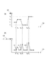
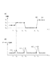
図4(a)は図2で示されるような画像データの水平方向の座標をx軸として、各x座標における輝度信号のグラフを示したものである。横軸402がx座標を表し、縦軸401は輝度レベルを示す。図4(b)は出力信号305、すなわちピーキング信号の図4(a)と同じ水平ラインにおけるx軸方向の分布を示したものであり、横軸404は図4(a)の横軸402と対応する。ピーキング信号の生成の仕方は様々な方法が提案されているが最も単純に概略を示すと「入力信号の変化量、すなわち微分値をピーキングレベル」として定義したものが図4である。410、411、412はピーキング信号のレベルを示し、図4(a)の信号の変化量が多いほど図4(b)のピーキング信号の値が大きくなることを示している。
FIG. 4A shows a graph of the luminance signal at each x-coordinate with the horizontal coordinate of the image data as shown in FIG. 2 as the x-axis. The
次にフォーカスアシスト時の拡大表示における問題点と本発明内容を述べる。フォーカスアシスト機能をONでスケーリング回路107での補間処理が拡大倍率であるとき、拡大補間時に滑らかな補間の代表である線形補間を使用した場合の輝度信号とピーキング信号の関係を示した図5に示す。
Next, problems in enlarged display during focus assist and the contents of the present invention will be described. FIG. 5 shows the relationship between the luminance signal and the peaking signal when linear interpolation, which is representative of smooth interpolation at the time of enlargement interpolation, is used when the focus assist function is ON and the interpolation processing in the
図5(a)は図4(a)の信号を2倍に線形補間したときの各画素の輝度を示す図である。丸印が第2の補間処理回路109への元々の入力信号501を示し、四角が第2の補間処理109の補間処理による補間画素502を示す。これらの信号をピーキング信号生成部114に入力して作成されるピーキング信号の分布を示す図が図5(b)である。図5についても図4と同様に入力輝度レベルとピーキング信号生成部で生成されるピーキング信号の対応を時間軸で取ったものとなる。
FIG. 5A shows the luminance of each pixel when the signal of FIG. 4A is linearly interpolated twice. A circle indicates the
線形補間で補間画素を作っているため表示デバイス113に映し出される映像は滑らかで奇麗な画質となる。反面、図5(b)の510、511、512で示すようにピーキング信号のレベルは図4(b)の場合の410、411、412に比べて約半分となってしまう。これでは有効なピーキング信号が生成しにくいという問題点が発生する。そこで本問題の対策として以下のように補間処理を行う。表示デバイス113で表示される画像信号そのものを処理するモニタ信号処理部110への入力信号には第1の補間処理回路108で第1の補間処理、すなわちキュービック補間処理や線形補間処理のような滑らかな映像となる補間処理を行う。一方、ピーキング信号を生成するピーキング信号生成部114への入力信号には、第2の補間処理回路109で第2の補間処理、すなわち最近傍補間処理(ニアレストネイバー法)によりエッジ情報を残した状態で信号を送る。図6は最近傍補間によるピーキング信号生成部の入力信号と出力信号を図示したものである。丸印がオリジナル信号601を示し、四角が補間画素602を示す。最近傍補間処理であるために補間後でもエッジ情報が失われないので、ピーキング信号のレベル610、611、612は410、411、412と同等レベルとなる。
Since the interpolated pixels are created by linear interpolation, the image projected on the
図8は撮影時の画像処理装置による表示デバイスへの画像表示処理の動作を示すフローチャートである。下記の処理は表示制御部116及び表示制御部116の指示により各部で実行される。まずS1000で予めユーザにより設定されているフォーカスアシスト機能の設定がONかOFFかを判断する。OFFの場合は、予めユーザにより設定されている記録画像サイズと表示デバイス113の画素数に応じてスケーリング倍率が決定(S1004)され、上述した処理を経た出力画像信号が表示デバイス113に出力される(S1005)。ONの場合は記録画像サイズ、表示デバイス113の画素数とフォーカスアシスト倍率に応じてスケーリング倍率が決定 (S1001)され、第1の補間処理と第2の補間処理で異なる補間処理が実施される(S1002)。その後、ピーキング生成回路114で生成されたピーキング情報を重畳(S1003)し表示デバイス113に出力される。
FIG. 8 is a flowchart showing the operation of image display processing on the display device by the image processing apparatus at the time of shooting. The following processing is executed in each unit according to instructions from the
以上のように、本実施形態では、画像のエッジ部分を確認するピーキング表示を、拡大画像について行う場合において、表示画像には滑らかな補間処理、ピーキング信号を生成する為の画像には第1の補間処理よりも高周波成分を残す(損ないにくい)補間処理で拡大処理を行う。これにより、より正確にピーキング情報を生成しながら表示デバイスには滑らかな表示映像を出力することが可能となる。 As described above, in the present embodiment, when peaking display for confirming the edge portion of an image is performed on an enlarged image, smooth interpolation processing is performed on the display image, and the first image is generated on the image for generating the peaking signal. The enlargement process is performed by an interpolation process that leaves a high-frequency component (less likely to be lost) than the interpolation process. This makes it possible to output a smooth display image to the display device while generating peaking information more accurately.
本実施形態では、フォーカス調整の際に合焦の程度を確認するためのピーキング情報の表示に関する実施形態を説明したが、本発明はこれに限らず、画像の拡大処理を伴ったピーキング表示であれば、その利用方法は問わない。 In the present embodiment, the embodiment related to the display of peaking information for confirming the degree of focus at the time of focus adjustment has been described. However, the present invention is not limited to this, and may be a peaking display accompanied by an image enlargement process. For example, the method of using it does not matter.
また、本実施形態では、第1の補間処理を線形補間処理、第2の補間処理を最近傍補間処理としたが、補間処理の組み合わせはこれに限らない。すなわち、第1の補間処理に比べて第2の補間処理の方がよりエッジの情報(高周波成分の情報)が残りやすい補間処理であればよい。例えば第1の補間処理がバイキュービック補間処理で、第2の補間処理が最近傍補間処理である場合、第1の補間処理が線形補間処理で、第2の補間処理がバイキュービック補間処理である場合などが考えられる。 In the present embodiment, the first interpolation process is a linear interpolation process and the second interpolation process is a nearest neighbor interpolation process, but the combination of interpolation processes is not limited to this. In other words, the second interpolation process may be an interpolation process in which edge information (high-frequency component information) is more likely to remain than the first interpolation process. For example, when the first interpolation process is a bicubic interpolation process and the second interpolation process is a nearest neighbor interpolation process, the first interpolation process is a linear interpolation process, and the second interpolation process is a bicubic interpolation process. Cases can be considered.
また、本実施形態では、モニタ信号処理部110の前段に第1の補間処理回路108を置くことで、モニタ信号処理部110に入力される画像信号の画像サイズ(画素数)が表示デバイス113に対応した一定のものになるように構成した。これにより、モニタ信号処理部110が簡易な構成で済むようにした。しかし、これに限らず、モニタ信号処理部110の後段に第1の補間処理回路108を置く構成でも本発明の目的、効果は達成できる。
In the present embodiment, the first
(第2の実施形態)
図7は第2の実施形態における画像処理装置の一例としての撮像装置であるデジタルカメラのブロック図である。第1の実施形態との違いは、スイッチ701が追加されたところである。モニタ信号処理回路110への入力信号を、表示制御部116の指示により、フォーカスアシスト時の拡大率に応じて第1の補間処理回路108からの出力か第2の補間処理回路109からの出力かで切り替える。
(Second Embodiment)
FIG. 7 is a block diagram of a digital camera that is an imaging apparatus as an example of an image processing apparatus according to the second embodiment. The difference from the first embodiment is that a
フォーカスアシスト時に拡大倍率が一定以上上がった場合の問題点として、補間処理1でバイキュービックに代表されるなめらかな補間処理で補間を行った場合、拡大率が非常に大きくなった場合には画像がぼけてしまうという問題点がある。そこで倍率判定回路701で所定の倍率より高いと判断した場合には110への入力信号を補間処理2と同じ近傍補間処理を用いる。これにより、意図的に滑らかではない画像を表示することでフォーカスアシスト時の拡大率が大きい時の表示画像の画像ぼけを防ぎ、合焦度合いの確認をしやすくすることが可能となる。
As a problem when the enlargement magnification is raised above a certain level at the time of focus assist, when interpolation is performed by a smooth interpolation process represented by bicubic in interpolation process 1, an image is displayed when the enlargement ratio becomes very large. There is a problem of being blurred. Therefore, if the
図9は第2の実施形態における撮影時の画像処理装置による表示デバイスへの画像表示処理の動作を示すフローチャートである。S2000、S2001、S2004、S2005、S2006は図8と同じであるため説明は省略する。 FIG. 9 is a flowchart showing an operation of image display processing on the display device by the image processing apparatus at the time of shooting in the second embodiment. S2000, S2001, S2004, S2005, and S2006 are the same as those in FIG.
S2002でスケーリング倍率が閾値を超えているかどうかを判定し、閾値を超えていない場合にはS2006に分岐し、表示制御部116の指示によりスイッチ701では第1の補間処理回路108からの出力が選択される。つまり以後は第1の実施形態と同一の処理となる。
In S2002, it is determined whether or not the scaling magnification exceeds the threshold value. If the threshold value is not exceeded, the process branches to S2006, and the output from the first
一方、スケーリング倍率が閾値を超えた場合は、表示制御部116の指示によりスイッチ701では第2の補間処理回路109からの出力が選択される。すなわち、モニタ信号処理部110に入力される画像もピーキング信号生成部114に入力される画像と同様の補間処理(最近傍補間処理)を実施(S2003)し、S2005でピーキング信号を重畳し表示デバイス113に出力される。
On the other hand, when the scaling magnification exceeds the threshold value, the output from the second
以上のように本実施形態では、表示画像が所定倍率より大きく拡大(補間)処理される場合には、表示用の画像としては滑らかになり過ぎないように、ピーキング信号生成部114と同様の補間処理により表示画像の拡大処理も行う。これにより、拡大倍率が大きい場合でも適切なフォーカス確認を行う画像が得られる。
As described above, in the present embodiment, when the display image is enlarged (interpolated) larger than a predetermined magnification, the same interpolation as that of the peaking
以上、本発明をその好適な実施形態に基づいて詳述してきたが、本発明はこれら特定の実施形態に限られるものではなく、この発明の要旨を逸脱しない範囲の様々な形態も本発明に含まれる。上述の実施形態の一部を適宜組み合わせてもよい。 Although the present invention has been described in detail based on preferred embodiments thereof, the present invention is not limited to these specific embodiments, and various forms within the scope of the present invention are also included in the present invention. included. A part of the above-described embodiments may be appropriately combined.
(他の実施形態)
本発明の目的は以下のようにしても達成できる。すなわち、前述した各実施形態の機能を実現するための手順が記述されたソフトウェアのプログラムコードを記録した記憶媒体を、システムまたは装置に供給する。そしてそのシステムまたは装置のコンピュータ(またはCPU、MPU等)が記憶媒体に格納されたプログラムコードを読み出して実行するのである。
(Other embodiments)
The object of the present invention can also be achieved as follows. That is, a storage medium in which a program code of software in which a procedure for realizing the functions of the above-described embodiments is described is recorded is supplied to the system or apparatus. The computer (or CPU, MPU, etc.) of the system or apparatus reads out and executes the program code stored in the storage medium.
この場合、記憶媒体から読み出されたプログラムコード自体が本発明の新規な機能を実現することになり、そのプログラムコードを記憶した記憶媒体およびプログラムは本発明を構成することになる。 In this case, the program code itself read from the storage medium realizes the novel function of the present invention, and the storage medium and program storing the program code constitute the present invention.
また、プログラムコードを供給するための記憶媒体としては、例えば、フレキシブルディスク、ハードディスク、光ディスク、光磁気ディスクなどが挙げられる。また、CD−ROM、CD−R、CD−RW、DVD−ROM、DVD−RAM、DVD−RW、DVD−R、磁気テープ、不揮発性のメモリカード、ROM等も用いることができる。 Examples of the storage medium for supplying the program code include a flexible disk, a hard disk, an optical disk, and a magneto-optical disk. Further, a CD-ROM, CD-R, CD-RW, DVD-ROM, DVD-RAM, DVD-RW, DVD-R, magnetic tape, nonvolatile memory card, ROM, or the like can also be used.
また、コンピュータが読み出したプログラムコードを実行可能とすることにより、前述した各実施形態の機能が実現される。さらに、そのプログラムコードの指示に基づき、コンピュータ上で稼動しているOS(オペレーティングシステム)等が実際の処理の一部または全部を行い、その処理によって前述した各実施形態の機能が実現される場合も含まれる。 Further, by making the program code read by the computer executable, the functions of the above-described embodiments are realized. Furthermore, when the OS (operating system) running on the computer performs part or all of the actual processing based on the instruction of the program code, the functions of the above-described embodiments are realized by the processing. Is also included.
更に、以下の場合も含まれる。まず記憶媒体から読み出されたプログラムコードが、コンピュータに挿入された機能拡張ボードやコンピュータに接続された機能拡張ユニットに備わるメモリに書き込まれる。その後、そのプログラムコードの指示に基づき、その機能拡張ボードや機能拡張ユニットに備わるCPU等が実際の処理の一部または全部を行う。 Furthermore, the following cases are also included. First, the program code read from the storage medium is written in a memory provided in a function expansion board inserted into the computer or a function expansion unit connected to the computer. Thereafter, based on the instruction of the program code, the CPU or the like provided in the function expansion board or function expansion unit performs part or all of the actual processing.
100 光学系
101 撮像素子
102 ディジタル信号処理部
103 フレームメモリ
107 スケーリング回路
108 第1の補間処理回路
109 第2の補間処理回路
110 モニタ信号処理部
111 ピーキング信号重畳回路
112 表示素子駆動部
113 表示デバイス
114 ピーキング信号生成部
115 スイッチ
116 表示制御部
117 表示ブロック
DESCRIPTION OF
Claims (8)
前記補間手段で補間処理が施された画像信号から、前記画像信号内の所定方向における信号レベルの変化量に応じたレベルを有するピーキング信号を生成するピーキング信号生成手段と、
前記補間手段で補間処理が施された画像信号に前記ピーキング信号生成手段で生成される前記ピーキング信号を重畳して、表示デバイスに表示させる表示制御手段と、を有し、
前記補間手段は、前記入力される画像信号に対して第1の補間処理と、前記第1の補間処理に比べて処理対象となる画像信号の高周波成分を残す第2の補間処理を施すことが可能であって、
前記表示制御手段は、前記補間手段で前記第1の補間処理を施して得られた画像信号に、前記補間手段で前記第2の補間処理を施して得られた画像信号から生成されたピーキング信号を重畳することを特徴とする画像処理装置。 Interpolation means for performing interpolation processing according to the enlargement magnification on the input image signal;
Peaking signal generation means for generating a peaking signal having a level corresponding to a change amount of a signal level in a predetermined direction in the image signal from the image signal subjected to interpolation processing by the interpolation means;
The peaking signal by superimposing the generated by the peaking signal generating means to an image signal interpolating process has been performed by said interpolation means comprises display control means for displaying on the Viewing device, a
The interpolation means may perform a first interpolation process on the input image signal and a second interpolation process that leaves a high-frequency component of the image signal to be processed as compared to the first interpolation process. Is possible,
The display control means includes a peaking signal generated from an image signal obtained by performing the second interpolation processing by the interpolation means on an image signal obtained by performing the first interpolation processing by the interpolation means. An image processing apparatus characterized by superimposing the images.
フォーカスレンズを含む光学系と、
前記光学系から入射される光を撮像する撮像手段と、
前記撮像手段のフォーカシングを制御する制御手段と、を有することを特徴とする撮像装置。 An image processing apparatus according to any one of claims 1 to 4,
An optical system including a focus lens;
Imaging means for imaging light incident from the optical system;
An image pickup apparatus comprising: control means for controlling focusing of the image pickup means.
前記補間ステップにおいて補間処理が施された画像信号から、前記画像信号内の所定方向における信号レベルの変化量に応じたレベルを有するピーキング信号を生成するピーキング信号生成ステップと、
前記補間ステップで補間処理が施された画像信号に前記ピーキング信号生成ステップで生成される前記ピーキング信号を重畳して、表示デバイスに表示させる表示制御ステップと、を有し、
前記補間ステップは、前記入力される画像信号に対して第1の補間処理と、前記第1の補間処理に比べて処理対象となる画像信号の高周波成分を残す第2の補間処理を施すことが可能であって、
前記表示制御ステップでは、前記補間ステップで前記第1の補間処理を施して得られた画像信号に、前記補間ステップで前記第2の補間処理を施して得られた画像信号から生成されたピーキング信号を重畳することを特徴とする画像処理装置の制御方法。 An interpolation step for performing an interpolation process according to the enlargement magnification on the input image signal;
A peaking signal generation step of generating a peaking signal having a level corresponding to a change amount of a signal level in a predetermined direction in the image signal from the image signal subjected to the interpolation processing in the interpolation step;
The peaking signal by superimposing the generated by the peaking signal generating step to the image signal interpolation processing has been performed in the interpolation step, has a display control step of displaying on the Viewing device,
In the interpolation step, a first interpolation process and a second interpolation process that leaves a high-frequency component of the image signal to be processed compared to the first interpolation process are performed on the input image signal. Is possible,
In the display control step, a peaking signal generated from the image signal obtained by performing the second interpolation processing in the interpolation step on the image signal obtained by performing the first interpolation processing in the interpolation step. A method for controlling an image processing apparatus, wherein:
Priority Applications (1)
| Application Number | Priority Date | Filing Date | Title |
|---|---|---|---|
| JP2012089698A JP6083946B2 (en) | 2012-04-10 | 2012-04-10 | Image processing apparatus and image processing apparatus control method |
Applications Claiming Priority (1)
| Application Number | Priority Date | Filing Date | Title |
|---|---|---|---|
| JP2012089698A JP6083946B2 (en) | 2012-04-10 | 2012-04-10 | Image processing apparatus and image processing apparatus control method |
Publications (2)
| Publication Number | Publication Date |
|---|---|
| JP2013219626A JP2013219626A (en) | 2013-10-24 |
| JP6083946B2 true JP6083946B2 (en) | 2017-02-22 |
Family
ID=49591254
Family Applications (1)
| Application Number | Title | Priority Date | Filing Date |
|---|---|---|---|
| JP2012089698A Expired - Fee Related JP6083946B2 (en) | 2012-04-10 | 2012-04-10 | Image processing apparatus and image processing apparatus control method |
Country Status (1)
| Country | Link |
|---|---|
| JP (1) | JP6083946B2 (en) |
Families Citing this family (1)
| Publication number | Priority date | Publication date | Assignee | Title |
|---|---|---|---|---|
| JP2024050150A (en) * | 2022-09-29 | 2024-04-10 | キヤノン株式会社 | IMAGING APPARATUS, CONTROL METHOD FOR IMAGING APPARATUS, PROGRAM, AND STORAGE MEDIUM |
Family Cites Families (5)
| Publication number | Priority date | Publication date | Assignee | Title |
|---|---|---|---|---|
| JP3505115B2 (en) * | 1999-04-28 | 2004-03-08 | 富士通株式会社 | Image processing device and program recording medium |
| JP3530907B2 (en) * | 2002-01-31 | 2004-05-24 | ミノルタ株式会社 | Digital camera |
| JP4455364B2 (en) * | 2004-03-09 | 2010-04-21 | キヤノン株式会社 | Resolution conversion method and apparatus |
| JP2008109369A (en) * | 2006-10-25 | 2008-05-08 | Olympus Imaging Corp | Imaging apparatus and image processing method |
| JP2008283442A (en) * | 2007-05-10 | 2008-11-20 | Olympus Corp | Imaging apparatus |
-
2012
- 2012-04-10 JP JP2012089698A patent/JP6083946B2/en not_active Expired - Fee Related
Also Published As
| Publication number | Publication date |
|---|---|
| JP2013219626A (en) | 2013-10-24 |
Similar Documents
| Publication | Publication Date | Title |
|---|---|---|
| JP3944151B2 (en) | Image processing method, image processing apparatus, and image processing program | |
| JP4978152B2 (en) | Projector, program, and information storage medium | |
| JP2004242113A (en) | Image recording and reproducing device, image photographing device and chromatic aberration correcting method | |
| JP2007281546A (en) | Imaging apparatus and imaging method | |
| JP2008283442A (en) | Imaging apparatus | |
| JP4433883B2 (en) | White balance correction device, white balance correction method, program, and electronic camera device | |
| JP2014082533A (en) | Image processing apparatus, image processing method and program | |
| JP6083946B2 (en) | Image processing apparatus and image processing apparatus control method | |
| JP5446955B2 (en) | Imaging device | |
| JP5386956B2 (en) | Projector, display adjustment method, display adjustment program, and recording medium | |
| JP2010273282A (en) | Image processing apparatus, imaging apparatus, and image processing program | |
| US20130188076A1 (en) | Image processing apparatus and method for controlling the same | |
| JP4633525B2 (en) | Focus detection device | |
| JP6557451B2 (en) | Imaging apparatus, control method therefor, and program | |
| JP4781670B2 (en) | Imaging device | |
| JP2012160942A (en) | Image display device and imaging device | |
| JP2011205442A (en) | Image processing apparatus, image processing method and program | |
| JP2010056817A (en) | Imaging apparatus | |
| JP2011155420A (en) | Camera shake correction device, imaging processing method and program | |
| JP2011135188A (en) | Image processing device and image capturing apparatus | |
| JP2009201062A (en) | Imaging device and imaging method | |
| JP2009200981A (en) | Video camera | |
| JP2007019593A (en) | Contour emphasizing signal generating circuit, image signal processing apparatus, imaging apparatus, contour emphasizing signal generating method, and program | |
| JP6547742B2 (en) | Imaging control apparatus, imaging apparatus and imaging control method | |
| JP2016092596A (en) | Imaging apparatus, image processing device, and method for controlling them |
Legal Events
| Date | Code | Title | Description |
|---|---|---|---|
| A621 | Written request for application examination |
Free format text: JAPANESE INTERMEDIATE CODE: A621 Effective date: 20150410 |
|
| A977 | Report on retrieval |
Free format text: JAPANESE INTERMEDIATE CODE: A971007 Effective date: 20160125 |
|
| A131 | Notification of reasons for refusal |
Free format text: JAPANESE INTERMEDIATE CODE: A131 Effective date: 20160209 |
|
| A521 | Request for written amendment filed |
Free format text: JAPANESE INTERMEDIATE CODE: A523 Effective date: 20160408 |
|
| A131 | Notification of reasons for refusal |
Free format text: JAPANESE INTERMEDIATE CODE: A131 Effective date: 20160607 |
|
| A521 | Request for written amendment filed |
Free format text: JAPANESE INTERMEDIATE CODE: A523 Effective date: 20160723 |
|
| A131 | Notification of reasons for refusal |
Free format text: JAPANESE INTERMEDIATE CODE: A131 Effective date: 20160830 |
|
| A521 | Request for written amendment filed |
Free format text: JAPANESE INTERMEDIATE CODE: A523 Effective date: 20160930 |
|
| TRDD | Decision of grant or rejection written | ||
| A01 | Written decision to grant a patent or to grant a registration (utility model) |
Free format text: JAPANESE INTERMEDIATE CODE: A01 Effective date: 20161227 |
|
| A61 | First payment of annual fees (during grant procedure) |
Free format text: JAPANESE INTERMEDIATE CODE: A61 Effective date: 20170124 |
|
| R151 | Written notification of patent or utility model registration |
Ref document number: 6083946 Country of ref document: JP Free format text: JAPANESE INTERMEDIATE CODE: R151 |
|
| LAPS | Cancellation because of no payment of annual fees |