JP6083201B2 - Medium support apparatus and recording apparatus - Google Patents
Medium support apparatus and recording apparatus Download PDFInfo
- Publication number
- JP6083201B2 JP6083201B2 JP2012249038A JP2012249038A JP6083201B2 JP 6083201 B2 JP6083201 B2 JP 6083201B2 JP 2012249038 A JP2012249038 A JP 2012249038A JP 2012249038 A JP2012249038 A JP 2012249038A JP 6083201 B2 JP6083201 B2 JP 6083201B2
- Authority
- JP
- Japan
- Prior art keywords
- medium
- base
- spacer
- vertical direction
- support
- Prior art date
- Legal status (The legal status is an assumption and is not a legal conclusion. Google has not performed a legal analysis and makes no representation as to the accuracy of the status listed.)
- Active
Links
Images


Description
本発明は、媒体を支持する媒体支持装置及び記録装置に関する。 The present invention relates to a medium support apparatus and a recording apparatus that support a medium.
従来から、媒体を支持する媒体支持装置が使用されている。このうち、媒体を支持する
媒体支持部を有し、該媒体支持部を高さ方向に移動可能な媒体支持装置が使用されている
。このような媒体支持装置は媒体支持部に支持する媒体の厚さに応じて該媒体支持部を高
さ方向に移動可能な構成となっているものが多いが、媒体の種類は増え続けており、これ
まで以上に様々な厚さの媒体を使用可能な媒体支持装置を提供することが望まれている。
Conventionally, a medium support device for supporting a medium has been used. Among these, a medium support device that has a medium support portion that supports a medium and is capable of moving the medium support portion in the height direction is used. Many of such medium support devices are configured to be able to move the medium support portion in the height direction according to the thickness of the medium supported by the medium support portion, but the types of media continue to increase. Therefore, it is desired to provide a media support device that can use media having various thicknesses more than ever.
特に、媒体支持装置を備え、布帛などの被記録媒体を該媒体支持装置に支持させて記録
を行う記録装置では、様々な厚さの媒体を使用することに対する要望が多く、さらに、特
に薄い媒体を使用する際における媒体支持部の高精度の高さ調整が望まれている。すなわ
ち、厚い媒体を使用可能でありながら、特に薄い媒体を使用する際において媒体支持部の
高さ調整を高精度で行うことが可能な媒体支持装置及び記録装置を提供することが望まれ
ている。
In particular, in a recording apparatus that includes a medium support device and performs recording by supporting a recording medium such as a fabric on the medium support device, there are many demands for using media of various thicknesses. Therefore, it is desired to adjust the height of the medium support portion with high accuracy. That is, it is desired to provide a medium support apparatus and a recording apparatus that can adjust the height of the medium support portion with high accuracy, particularly when using a thin medium, while a thick medium can be used. .
媒体支持部の高さ調整を行うことが可能な媒体支持装置に関する技術として、例えば、
特許文献1には、被記録媒体を支持するプラテンの支持部材として弾性体が設けられ、該
弾性体の圧縮度合いを可変な媒体支持部を備えた記録装置が開示されている。
As a technique related to a medium support apparatus capable of adjusting the height of the medium support part, for example,
しかしながら、特許文献1の記録装置は、該弾性体の圧縮度合いを変えることにより媒
体支持部の高さ調整を行うことは可能であるが、その調整可能範囲は狭く、使用できる媒
体は限られる。このように、厚い媒体を使用可能でありながら、特に薄い媒体を使用する
際において媒体支持部の高さ調整を高精度で行うことが可能な媒体支持装置はこれまでな
かった。
However, although the recording apparatus of
そこで、本発明の目的は、厚い媒体を使用可能でありながら、特に薄い媒体を使用する
際において媒体支持部の高さ調整を高精度で行うことが可能な媒体支持装置を提供するこ
とである。
Accordingly, an object of the present invention is to provide a medium support device that can adjust the height of a medium support portion with high accuracy, particularly when using a thin medium, while a thick medium can be used. .
上記課題を解決するための本発明の第1の態様の媒体支持装置は、媒体を直接又は別の
部材を介して支持し、該媒体を支持する側とは反対側にピンが設けられている支持台と、
前記ピンを介して前記支持台を支持し、該支持台を鉛直方向に移動可能な移動機構と、前
記移動機構を支持可能な基部と、前記移動機構と前記基部との間に着脱可能なスペーサー
と、を備え、前記スペーサーは、鉛直方向と交差する方向において、前記ピンにおける鉛
直方向の延長線上の位置に対応する部分を含む大きさであることを特徴とする。
The medium support apparatus according to the first aspect of the present invention for solving the above-mentioned problems supports a medium directly or via another member, and a pin is provided on the side opposite to the side that supports the medium. A support base;
A support mechanism that supports the support base via the pins and is capable of moving the support base in a vertical direction, a base that can support the movement mechanism, and a spacer that is detachable between the movement mechanism and the base. The spacer has a size including a portion corresponding to a position on an extension line in the vertical direction of the pin in a direction intersecting the vertical direction.
ここで、「媒体を直接又は別の部材を介して支持し」とは、前記支持台が、直接媒体を
支持する媒体支持部を兼ねている場合と、媒体支持トレイ等の別の部材を介して媒体を支
持する場合の両方を含む意味である。また、ここでの「鉛直方向」とは、前記支持台から
前記移動機構に重力がかかる方向であり、厳密な意味での鉛直方向のほか、厳密な意味で
の鉛直方向から多少傾いた方向も含む意味である。
Here, “supporting the medium directly or via another member” means that the support base also serves as a medium support portion for directly supporting the medium, and a case where another medium such as a medium support tray is used. This includes both of the cases of supporting the medium. In addition, the “vertical direction” here is a direction in which gravity is applied to the moving mechanism from the support base, and in addition to the vertical direction in a strict sense, a direction slightly inclined from the vertical direction in a strict sense is also included. Including meaning.
本態様によれば、前記支持台を鉛直方向に移動可能な手段として前記移動機構と前記ス
ペーサーとを備えている。このため、薄い媒体を使用する際には前記移動機構により高精
度に前記支持台の位置を鉛直方向に調整でき、厚い媒体を使用する際には前記スペーサー
を外したうえで前記移動機構により調整することで前記支持台の位置を鉛直方向に調整で
きる。
According to this aspect, the moving mechanism and the spacer are provided as means for moving the support base in the vertical direction. Therefore, when using a thin medium, the position of the support base can be adjusted in the vertical direction with high accuracy by the moving mechanism. When using a thick medium, the moving mechanism is adjusted after removing the spacer. By doing so, the position of the support base can be adjusted in the vertical direction.
また、前記スペーサーの大きさによっては前記支持台及びこれに支持された媒体の重さ
により前記移動機構が変形し破損することも有り得る。しかし、本態様によれば、前記ス
ペーサーは、鉛直方向と交差する方向において、前記ピンにおける鉛直方向の延長線上の
位置に対応する部分を含む大きさであるので、前記スペーサーが前記移動機構を確りと支
えることが可能な構成となっている。このため、移動機構の変形及び破損を抑制すること
ができる。
なお、「鉛直方向の延長線上の位置に対応する部分を含む大きさ」には、鉛直方向の延
長線上の位置を含む大きさは当然含まれる。さらに、鉛直方向の延長線上の位置を厳密に
は含まない大きさであっても、該位置の近傍部分を含み前記移動機構の変形及び破損を抑
制する効果を有する大きさであれば該大きさも含まれる。
Further, depending on the size of the spacer, the moving mechanism may be deformed and damaged by the weight of the support base and the medium supported by the support base. However, according to this aspect, the spacer has a size including a portion corresponding to a position on the vertical extension line of the pin in a direction crossing the vertical direction, so that the spacer secures the moving mechanism. It can be supported. For this reason, deformation and breakage of the moving mechanism can be suppressed.
The “size including a portion corresponding to the position on the extension line in the vertical direction” naturally includes the size including the position on the extension line in the vertical direction. Further, even if the size does not strictly include the position on the extension line in the vertical direction, if the size includes the vicinity of the position and has an effect of suppressing deformation and breakage of the moving mechanism, the size is also sufficient. included.
本発明の第2の態様の媒体支持装置は、前記第1の態様において、前記移動機構は、鉛
直方向を回転軸の方向として回転可能であって回転に対応して鉛直方向に前記支持台を移
動可能な回転レバーと、前記回転レバーに設けられ、前記基部と接触することにより該回
転レバーの回転範囲を制限するストッパーと、を有し、前記ストッパーは、前記移動機構
と前記基部との間への前記スペーサーの設置有無に拘らず前記基部と接触可能であること
を特徴とする。
The medium support device according to a second aspect of the present invention is the medium support device according to the first aspect, wherein the moving mechanism is rotatable with the vertical direction as the direction of the rotation axis, and the support base is rotated in the vertical direction corresponding to the rotation. A movable rotation lever, and a stopper provided on the rotation lever and limiting a rotation range of the rotation lever by contacting the base, and the stopper is disposed between the movement mechanism and the base. It is possible to contact with the base portion regardless of whether or not the spacer is installed.
本態様によれば、回転レバーという簡単な構成で高精度の移動機構を構成できるととも
に、別途新たな構成部材を設けることなく簡単な構成で該回転レバーの回転範囲を制限す
るストッパーを設けることができる。また、前記移動機構と前記基部との間への前記スペ
ーサーの設置有無に拘らず前記基部と接触可能であるため、前記ストッパーに前記スペー
サーの設置有無に拘らずストッパーとしての機能を有させることができる。
According to this aspect, a highly accurate moving mechanism can be configured with a simple configuration of a rotary lever, and a stopper that limits the rotation range of the rotary lever can be provided with a simple configuration without providing a separate new component. it can. Further, since the base can be contacted regardless of whether the spacer is installed between the moving mechanism and the base, the stopper can have a function as a stopper regardless of whether the spacer is installed. it can.
本発明の第3の態様の媒体支持装置は、前記第1又は2の態様において、前記スペーサ
ー及び前記基部の少なくとも一方は、前記支持台の鉛直方向における位置を示す表示部を
有し、前記移動機構は、鉛直方向を回転軸の方向として回転可能であって回転に対応して
鉛直方向に前記支持台を移動可能な回転レバーと、前記回転レバーに設けられ、該回転レ
バーの持ち手部分における鉛直方向の延長線上とは異なる位置に、前記支持台の鉛直方向
における位置を前記表示部から指し示す指示部と、を備えることを特徴とする。
The medium support device according to a third aspect of the present invention is the medium support device according to the first or second aspect, wherein at least one of the spacer and the base has a display unit indicating a position in a vertical direction of the support base, and the movement The mechanism is provided on the rotary lever, which is rotatable on the vertical lever as the direction of the rotation axis and can move the support base in the vertical direction corresponding to the rotation. And a pointing unit for pointing the position of the support base in the vertical direction from the display unit at a position different from the vertical extension line.
ここで「前記支持台の鉛直方向における位置を示す表示部」とは、前記支持台の鉛直方
向における位置に関する情報を表す表示がされているものであれば特に限定されず、例え
ば、使用する媒体の名称のほか数字やアルファベット等の表示がされたものでもよい。
本態様によれば、簡単な構成で、且つ、ユーザーが見やすい状態で前記支持台の鉛直方
向における位置を指し示すことができる。
Here, the “display unit indicating the position of the support base in the vertical direction” is not particularly limited as long as it displays information related to the position of the support base in the vertical direction. In addition to the name, numbers or alphabets may be displayed.
According to this aspect, the position of the support base in the vertical direction can be pointed out with a simple configuration and in a state that is easy for the user to see.
本発明の第4の態様の媒体支持装置は、前記第2又は3の態様において、前記スペーサ
ー及び前記基部は、前記回転レバーの回転に伴う前記基部に対する前記スペーサーの回転
を抑制する回転抑制構造を有することを特徴とする。
The medium supporting device according to a fourth aspect of the present invention is the medium supporting device according to the second or third aspect, wherein the spacer and the base have a rotation suppressing structure that suppresses rotation of the spacer relative to the base due to rotation of the rotating lever. It is characterized by having.
本態様によれば、前記スペーサーが前記回転レバーの回転に伴って前記基部に対して回
転することを抑制することができる。特に、前記支持台の鉛直方向における位置に対応す
る表示が前記スペーサーにされている媒体支持装置において、前記スペーサーが回転する
ことによってユーザーが該表示を見誤ることを抑制することができる。
According to this aspect, it can suppress that the said spacer rotates with respect to the said base part with rotation of the said rotation lever. In particular, in the medium support device in which the display corresponding to the position in the vertical direction of the support base is the spacer, it is possible to prevent the user from mistaking the display as the spacer rotates.
本発明の第5の態様の媒体支持装置は、前記第1から第4のいずれか1つの態様におい
て、前記スペーサーは、前記基部に設けられた回転支点部を有し、該回転支点部を支点と
して該スペーサーを回転させることにより前記移動機構と前記基部との間に着脱可能とな
ることを特徴とする。
In the medium supporting device according to a fifth aspect of the present invention, in any one of the first to fourth aspects, the spacer has a rotation fulcrum provided on the base, and the rotation fulcrum is supported on the rotation fulcrum. As described above, the spacer is made detachable between the moving mechanism and the base by rotating the spacer.
本態様によれば、簡単な構成により前記スペーサーを前記移動機構と前記基部との間に
着脱可能に設置できる。
According to this aspect, the spacer can be detachably installed between the moving mechanism and the base portion with a simple configuration.
本発明の第6の態様の記録装置は、前記第1から第5のいずれか1つの媒体支持装置と
、前記媒体支持装置に支持された媒体に記録を行う記録部と、を備えることを特徴とする
。
A recording apparatus according to a sixth aspect of the present invention includes any one of the first to fifth medium support devices, and a recording unit that performs recording on a medium supported by the medium support device. And
本態様によれば、厚い被記録媒体を使用可能でありながら、特に薄い被記録媒体を使用
する際において支持台の高さ調整を高精度で行うことが可能になる。
According to this aspect, while it is possible to use a thick recording medium, it is possible to adjust the height of the support base with high accuracy, particularly when using a thin recording medium.
以下に、本発明の実施例に係る記録装置について、添付図面を参照して詳細に説明する
。
また、下記の実施例では媒体支持装置を備えた記録装置を用いて説明している。しかし
、本発明の媒体支持装置は、記録装置に備えられた媒体支持装置に限定されるわけではな
い。
また、下記の実施例では記録装置として記録ヘッドからインクを吐出して記録を行うイ
ンクジェット記録装置を用いて説明している。しかし、本発明の記録装置は、インクジェ
ット記録装置に限定されるわけではない。
Hereinafter, a recording apparatus according to an embodiment of the present invention will be described in detail with reference to the accompanying drawings.
Further, in the following embodiments, description is made using a recording apparatus provided with a medium support device. However, the medium support apparatus of the present invention is not limited to the medium support apparatus provided in the recording apparatus.
In the following embodiments, an ink jet recording apparatus that performs recording by ejecting ink from a recording head will be described as the recording apparatus. However, the recording apparatus of the present invention is not limited to the ink jet recording apparatus.
[実施例1](図1〜図9)
最初に、本発明の実施例1に係る記録装置について説明する。
図1は本発明の実施例1に係る記録装置1の概略斜視図であり、図2は本発明の実施例
1に係る記録装置1の概略正面図である。
本実施例の記録装置1は、媒体支持部2に支持された媒体を搬送方向Aに搬送する媒体
搬送部3を備えている。媒体支持部2は、媒体を支持する媒体支持トレイとしてのトレイ
4と、トレイ4を支持する支持台としてのステージ5とを備えている。トレイ4は、媒体
支持部2の移動機構としての回転レバー6を回転させることにより、鉛直方向でもある高
さ方向Cに移動する。なお、高さ方向Cは、媒体支持部2から回転レバー6に重力がかか
る方向であり、本実施例の記録装置1では厳密な意味での鉛直方向であるが、厳密な意味
での鉛直方向から多少傾いた方向であっても構わない。
なお、本実施例の記録装置1では、支持台としてのステージ5がトレイ4を介して媒体
を支持する構成であるが、支持台が直接媒体を支持し媒体支持部を兼ねている構成でもよ
い。
[Example 1] (FIGS. 1 to 9)
First, the recording apparatus according to the first embodiment of the invention will be described.
FIG. 1 is a schematic perspective view of a
The
In the
また、記録装置1の本体内部には記録部としての記録ヘッド(不図示)が備えられてい
る。そして、本実施例の記録装置1は、搬送方向Aと交差する走査方向Bに記録ヘッドを
往復移動させながら、記録ヘッドから媒体支持部2に支持された媒体にインクを吐出させ
て所望の画像を形成する。なお、本実施例の記録装置1は、図1中の手前側(左下方向)
が媒体支持部2への媒体のセット位置である。記録装置1は、セット位置から図1中の奥
側(右上方向)の記録開始位置まで媒体をセットした媒体支持部2を移動した後、図1中
の手前側に媒体支持部2を移動しながら記録する。図1は、媒体支持部2が記録開始位置
にある状態を表している。
In addition, a recording head (not shown) as a recording unit is provided inside the main body of the
Is the set position of the medium on the
次に、本発明の実施例1に係る記録装置1の要部である媒体支持装置について説明する
。
図3は、本発明の実施例1に係る記録装置1の要部である媒体支持装置7の斜視図であ
る。
本実施例の媒体支持装置7は、ステージ5と、回転レバー6と、回転レバー6を支持可
能な基部としてのアーム8と、媒体の裾受けとなる下部トレイ9と、を備えている。また
、回転レバー6とアーム8との間に着脱可能なスペーサー10を備えている。なお、媒体
支持装置7はさらに、媒体を支持するトレイ4を着脱可能に備えているが、図3はトレイ
4を外した状態を表している。
Next, a medium support apparatus that is a main part of the
FIG. 3 is a perspective view of the
The
媒体支持部2を構成するステージ5には、媒体を支持する側である上側とは反対側の下
側に突出したピン11が三ケ所設けられている。ピン11は、回転レバー6に設けられた
階段状の支持部12に支持されている。ユーザーは、回転レバー6に設けられた持ち手部
分13を持って回転レバー6を高さ方向Cと交差する方向に回転させる。こうすることに
より、階段状の支持部12に支持されたピン11の高さ方向Cの位置が変動し、これに伴
いステージ5(媒体支持部2)の高さ方向Cの位置が変動する。別の表現をすると、回転
レバー6は、高さ方向Cを回転軸の方向として回転可能であって、回転に対応して高さ方
向Cにステージ5を移動可能である。なお、回転レバー6には、アーム8と接触すること
により該回転レバー6の回転範囲を制限するストッパー14が設けられている。
なお、ステージ5は、柱状部21、22を有し、柱状部21、22をアーム8に設けら
れた穴に通すことにより水平方向に位置決めされる。
The
The
次に、本発明の実施例1に係る記録装置1におけるスペーサー10の着脱について説明
する。
図4は、本発明の実施例1に係る記録装置1の要部である媒体支持装置7の側面図であ
り、媒体支持装置7にスペーサー10を装着した状態を表した図である。
スペーサー10は、回転レバー6とアーム8との間に装着されている。本実施例の記録
装置1では、相対的に高さ方向Cの厚さが薄い媒体を被記録媒体として使用する場合にス
ペーサー10が装着される。ユーザーは、薄い被記録媒体に記録を行う場合、スペーサー
10を媒体支持装置7に装着し、回転レバー6の持ち手部分13を持って回転レバー6を
回転させることにより高精度にステージ5の高さ調整を行うことが可能である。
Next, attachment / detachment of the
FIG. 4 is a side view of the
The
図5は、本発明の実施例1に係る記録装置1の要部である媒体支持装置7の側面図であ
り、媒体支持装置7からスペーサー10を外した状態を表した図である。
ユーザーは、相対的に高さ方向Cの厚さが厚い被記録媒体に記録を行う場合、スペーサ
ー10を媒体支持装置7から外し、回転レバー6の持ち手部分13を持って回転レバー6
を回転させることにより高精度にステージ5の高さ調整を行うことが可能である。本実施
例の記録装置1は、スペーサー10を媒体支持装置7に対して着脱可能な構成とすること
によって、スペーサー10を外して厚い媒体を使用可能とするとともに、回転レバー6に
よる高精度な高さ調整を可能としている。
なお、スペーサーを用いることによるメリットとして、厚い被記録媒体を用いた場合に
おいて、該被記録媒体が記録ヘッドに接触することによる記録ヘッドの破損を回避可能で
あることが挙げられる。また、被記録媒体の高さ調整のための特別な機構が必要なく、構
造の簡素化・低コスト化が図れることが挙げられる。
FIG. 5 is a side view of the
When recording on a recording medium having a relatively large thickness in the height direction C, the user removes the
By rotating the, it is possible to adjust the height of the
An advantage of using the spacer is that, when a thick recording medium is used, it is possible to avoid damage to the recording head due to the recording medium contacting the recording head. Further, there is no need for a special mechanism for adjusting the height of the recording medium, and the structure can be simplified and the cost can be reduced.
なお、本実施例の記録装置1は、媒体支持装置7にスペーサー10を装着した状態及び
媒体支持装置7からスペーサー10を外した状態のいずれの状態においても、ストッパー
14はアーム8と接触可能な構成となっている。すなわち、ストッパー14は、回転レバ
ー6とアーム8との間へのスペーサー10の設置有無に拘らずアーム8と接触可能である
。このような構成により、ストッパー14にスペーサー10の設置有無に拘らずストッパ
ーとしての機能を有させている。
In the
次に、本発明の実施例1に係る記録装置1におけるステージ5に設けられた三ヶ所のピ
ン11と回転レバー6及びスペーサー10との位置関係について説明する。
図6は、本発明の実施例1に係る記録装置1の要部平面図であり、ピン11と回転レバ
ー6との位置関係を表す図である。
三ヶ所のピン11は、何れも回転レバー6に設けられた階段状の支持部12に支持され
ている。支持部12は階段状となっているため、ユーザーは持ち手部分13を持って回転
レバー6を回転させることによりその回転に対応して高さ方向Cにステージ5を移動可能
になる。すなわち、持ち手部分13の移動量(回転量)に従ってステージ5の高さが決ま
る構成となっている。
Next, the positional relationship between the three
FIG. 6 is a plan view of the main part of the
The three
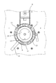
図7は、本発明の実施例1に係る記録装置1の要部平面図であり、ピン11とスペーサ
ー10との位置関係を表す図である。
三ヶ所のピン11は、何れも回転レバー6を介してスペーサー10上に支持されている
。別の表現をすると、スペーサー10は、高さ方向Cと交差する方向において、ピン11
における高さ方向Cの延長線上の位置に対応する部分を含む大きさである。このため、回
転レバー6の変形及び破損を抑制することができる。スペーサー10の大きさがピン11
における高さ方向Cの延長線上の位置に対応する部分を含む大きさでない場合、回転レバ
ー6にはスペーサー10の支えが無い位置に下向きの力が加わる。この場合、回転レバー
6を支える部材が下側に無い状態となるので回転レバー6の変形及び破損が発生しやすく
なるためである。
FIG. 7 is a plan view of the main part of the
The three
It is a magnitude | size including the part corresponding to the position on the extension line | wire of the height direction C in FIG. For this reason, deformation and breakage of the
If the size does not include a portion corresponding to the position on the extended line in the height direction C, a downward force is applied to the
なお、ピン11における高さ方向Cの延長線上の位置に対応する部分を含む大きさには
、回転レバー6の変形及び破損を抑制する効果があれば、高さ方向Cの延長線上の位置を
厳密には含まない大きさであっても、該位置の近傍部分を含む大きさであれば含まれる。
高さ方向Cの延長線上の位置を厳密には含まない大きさであっても、該位置の近傍部分を
含む大きさであれば、回転レバー6の変形及び破損を抑制する効果がある場合があるため
である。
Note that the size of the
Even if it is a size that does not strictly include the position on the extension line in the height direction C, it may be effective to suppress deformation and breakage of the
また、本実施例の記録装置1のアーム8には、回転レバー6及びスペーサー10を嵌め
込むことが可能な嵌め込み部15が設けられている。そして、嵌め込み部15は一部にフ
ラット部分16が設けられ、スペーサー10もこれに対応して一部がフラットとなってい
る。嵌め込み部15とスペーサー10の一部をフラットにし、両者のフラット部分を合わ
せて嵌め込むことによって、回転レバー6を回転させる際にスペーサー10がアーム8に
対して回転することを抑制している。すなわち、スペーサー10及びアーム8は、回転レ
バー6の回転に伴うアーム8に対するスペーサー10の回転を抑制する回転抑制構造をし
ている。
Further, the
このような構成によって、スペーサー10が回転レバー6の回転に伴ってアーム8に対
して回転することを抑制することができる。特に、本実施例の記録装置1は、ステージ5
の高さ方向Cにおける位置を示す表示部17がスペーサー10に設けられているが、この
ような構成の場合、スペーサー10が回転することによってユーザーが該表示部17を見
誤ることを抑制することができる。なお、本実施例の記録装置1は、回転抑制構造として
嵌め込み部15とスペーサー10とにフラット部分を設ける構造としたが、このような構
造に限定されず、例えば、嵌め込み部15とスペーサー10とに凸部と凹部とを設ける構
造等でもよい。
With such a configuration, it is possible to suppress the
The
次に、本発明の実施例1に係る記録装置1におけるスペーサー10に設けられたステー
ジ5の高さ方向Cにおける位置に対応する表示部17と、回転レバー6に設けられステー
ジ5の高さ方向Cにおける位置を表示部17から指し示す指示部18について説明する。
図8及び図9は、本発明の実施例1に係る記録装置1の要部正面図であり、ステージ5
の高さ方向Cにおける位置を指示部18が表示部17から指し示している状態を表す図で
ある。
Next, the
8 and 9 are main part front views of the
It is a figure showing the state which the instruction |
本実施例の記録装置1は、スペーサー10にステージ5の高さ方向Cにおける位置に対
応する表示部17が設けられている。本実施例の記録装置1における表示部17には1か
ら8までの数字が表示されており、数字が大きくなるほど厚い媒体に対応する(数字が大
きくなるほどステージ5の高さ方向Cにおける位置が低くなる)。図8では、指示部18
により数字の1が指し示されており、薄い媒体に対応する状態が表されている。なお、本
実施例の表示部17には数字が表示されているが、この表示はステージ5の高さ方向Cに
おける位置に対応する表示であれば特に限定されない。すなわち、ステージ5の高さ方向
Cにおける位置に関する情報を表すものであれば特に限定されず、例えば、使用する媒体
の名称のほかアルファベット等の表示でもよい。
In the
The
また、本実施例の記録装置1では、回転レバー6には、該回転レバー6の持ち手部分1
3における高さ方向Cの延長線上とは異なる位置に、ステージ5の高さ方向Cにおける位
置を表示部17から指し示す指示部18が設けられている。このような構成とすることに
より、簡単な構成で、且つ、ユーザーが見やすい状態でステージ5の高さ方向Cにおける
位置を指し示すことができる。ただし、本発明はこのような構成に限定されない。
Further, in the
3 is provided at a position different from the extension line in the height direction C in FIG. 3 to indicate the position in the height direction C of the
図9では、指示部18により数字の8が指し示されており、図8の状態で使用する媒体
よりも厚い媒体に対応する状態が表されている。また、本実施例の記録装置1は、スペー
サー10を取り外すことにより、図9の状態で使用する媒体よりもさらに厚い媒体に対応
することもできる。なお、本実施例の記録装置1は、スペーサー10に表示部17が設け
られているが、本発明はこのような構成に限定されず、例えば、アーム8に表示部17が
設けられていてもよい。
In FIG. 9,
[実施例2](図10)
次に、本発明の実施例2に係る記録装置について説明する。
図10は、本発明の実施例2に係る記録装置1の要部である媒体支持装置7の側面図で
ある。なお、実施例1と共通する構成部材は同じ符号で示しており、詳細な説明は省略す
る。
[Example 2] (FIG. 10)
Next, a recording apparatus according to the second embodiment of the invention will be described.
FIG. 10 is a side view of the
本実施例の媒体支持装置7のアーム8には、回転支点部19が設けられ、スペーサー1
0と回転支点部19とは接続部20を介して接続されている。本実施例の媒体支持装置7
は、回転支点部19を回転軸(支点)とし高さ方向Cを回転軸の方向として接続部20及
びスペーサー10を回転可能である。詳細には、ステージ5と回転レバー6とを一旦取り
外すことで、接続部20を介してスペーサー10を回転可能である。このような構成とす
ることにより、簡単な構成で、スペーサー10を回転レバー6とアーム8との間に着脱可
能に設置できる。
The
0 and the
Can rotate the connecting
1 記録装置、2 媒体支持部、3 媒体搬送部、4 トレイ(媒体支持トレイ)、
5 ステージ(支持台)、6 回転レバー(移動機構)、7 媒体支持装置、
8 アーム、9 下部トレイ、10 スペーサー、11 ピン、12 支持部、
13 持ち手部分、14 ストッパー、15 嵌め込み部、 16 フラット部分、
17 表示部、18 指示部、19 回転支点部、20 接続部、21 柱状部、
22 柱状部
1 recording device, 2 medium support section, 3 medium transport section, 4 tray (medium support tray),
5 stage (support), 6 rotation lever (movement mechanism), 7 medium support device,
8 arms, 9 lower tray, 10 spacers, 11 pins, 12 support parts,
13 handle part, 14 stopper, 15 fitting part, 16 flat part,
17 display part, 18 indicating part, 19 rotation fulcrum part, 20 connecting part, 21 columnar part,
22 Columnar part
Claims (5)
前記ピンを介して前記支持台を支持し、該支持台を鉛直方向に移動可能な移動機構と、
前記移動機構を支持可能な基部と、
前記移動機構と前記基部との間に着脱可能なスペーサーと、を備え、
前記スペーサーは、鉛直方向と交差する方向において、前記ピンにおける鉛直方向の延長線上の位置に対応する部分を含む大きさであり、
前記移動機構は、
鉛直方向を回転軸の方向として回転可能であって、回転に対応して鉛直方向に前記支持台を移動可能な回転レバーと、
前記回転レバーに設けられ、前記基部と接触することにより該回転レバーの回転範囲を制限するストッパーと、を有し、
前記ストッパーは、前記移動機構と前記基部との間への前記スペーサーの設置有無に拘らず前記基部と接触可能であることを特徴とする媒体支持装置。 A support base that supports the medium directly or via another member, and a pin is provided on the side opposite to the side that supports the medium;
A support mechanism for supporting the support base via the pins, and a movement mechanism capable of moving the support base in a vertical direction;
A base capable of supporting the moving mechanism;
A removable spacer between the moving mechanism and the base,
The spacer is in the direction intersecting the vertical direction, Ri magnitude der including a portion corresponding to a position on an extension line of the vertical direction in the pin,
The moving mechanism is
A rotation lever that can rotate with the vertical direction as the direction of the rotation axis, and can move the support base in the vertical direction in response to the rotation;
A stopper provided on the rotating lever and limiting a rotation range of the rotating lever by contacting the base,
The medium support device according to claim 1, wherein the stopper can contact the base portion regardless of whether the spacer is installed between the moving mechanism and the base portion .
前記ピンを介して前記支持台を支持し、該支持台を鉛直方向に移動可能な移動機構と、
前記移動機構を支持可能な基部と、
前記移動機構と前記基部との間に着脱可能なスペーサーと、を備え、
前記スペーサーは、鉛直方向と交差する方向において、前記ピンにおける鉛直方向の延長線上の位置に対応する部分を含む大きさであり、
前記スペーサー及び前記基部の少なくとも一方は、前記支持台の鉛直方向における位置を示す表示部を有し、
前記移動機構は、
鉛直方向を回転軸の方向として回転可能であって回転に対応して該鉛直方向に前記支持台を移動可能な回転レバーと、
前記回転レバーに設けられ、該回転レバーの持ち手部分における鉛直方向の延長線上とは異なる位置に、前記支持台の鉛直方向における位置を前記表示部から指し示す指示部と、を備えることを特徴とする媒体支持装置。 A support base that supports the medium directly or via another member, and a pin is provided on the side opposite to the side that supports the medium;
A support mechanism for supporting the support base via the pins, and a movement mechanism capable of moving the support base in a vertical direction;
A base capable of supporting the moving mechanism;
A removable spacer between the moving mechanism and the base,
The spacer is a size including a portion corresponding to a position on an extension line in the vertical direction of the pin in a direction intersecting the vertical direction,
At least one of the spacer and the base has a display unit indicating a position in the vertical direction of the support base,
The moving mechanism is
A rotation lever that is rotatable with the vertical direction as the direction of the rotation axis and is capable of moving the support base in the vertical direction corresponding to the rotation;
An indicator that is provided on the rotary lever and points at a position in the vertical direction of the support base from the display unit at a position different from a vertical extension line of a handle portion of the rotary lever. Media support device.
前記スペーサー及び前記基部は、前記回転レバーの回転に伴う前記基部に対する前記スペーサーの回転を抑制する回転抑制構造を有することを特徴とする媒体支持装置。 The medium support device according to claim 1 or 2 ,
The medium support device according to claim 1, wherein the spacer and the base have a rotation suppression structure that suppresses rotation of the spacer relative to the base due to rotation of the rotating lever.
前記ピンを介して前記支持台を支持し、該支持台を鉛直方向に移動可能な移動機構と、
前記移動機構を支持可能な基部と、
前記移動機構と前記基部との間に着脱可能なスペーサーと、を備え、
前記スペーサーは、鉛直方向と交差する方向において、前記ピンにおける鉛直方向の延長線上の位置に対応する部分を含む大きさであり、前記基部に設けられた回転支点部を有し、該回転支点部を支点として該スペーサーを回転させることにより前記移動機構と前記基部との間に着脱可能となることを特徴とする媒体支持装置。 A support base that supports the medium directly or via another member, and a pin is provided on the side opposite to the side that supports the medium;
A support mechanism for supporting the support base via the pins, and a movement mechanism capable of moving the support base in a vertical direction;
A base capable of supporting the moving mechanism;
A removable spacer between the moving mechanism and the base,
The spacer has a size that includes a portion corresponding to a position on an extension line in the vertical direction of the pin in a direction intersecting the vertical direction , and has a rotation fulcrum portion provided on the base, and the rotation fulcrum portion By rotating the spacer about the fulcrum, the medium supporting device can be attached and detached between the moving mechanism and the base.
前記媒体支持装置に支持された媒体に記録を行う記録部と、を備えることを特徴とする記録装置。 The medium support device according to any one of claims 1 to 4 ,
And a recording unit that performs recording on a medium supported by the medium support device.
Priority Applications (1)
| Application Number | Priority Date | Filing Date | Title |
|---|---|---|---|
| JP2012249038A JP6083201B2 (en) | 2012-11-13 | 2012-11-13 | Medium support apparatus and recording apparatus |
Applications Claiming Priority (1)
| Application Number | Priority Date | Filing Date | Title |
|---|---|---|---|
| JP2012249038A JP6083201B2 (en) | 2012-11-13 | 2012-11-13 | Medium support apparatus and recording apparatus |
Publications (2)
| Publication Number | Publication Date |
|---|---|
| JP2014097585A JP2014097585A (en) | 2014-05-29 |
| JP6083201B2 true JP6083201B2 (en) | 2017-02-22 |
Family
ID=50940038
Family Applications (1)
| Application Number | Title | Priority Date | Filing Date |
|---|---|---|---|
| JP2012249038A Active JP6083201B2 (en) | 2012-11-13 | 2012-11-13 | Medium support apparatus and recording apparatus |
Country Status (1)
| Country | Link |
|---|---|
| JP (1) | JP6083201B2 (en) |
Families Citing this family (1)
| Publication number | Priority date | Publication date | Assignee | Title |
|---|---|---|---|---|
| JP6364989B2 (en) * | 2014-06-18 | 2018-08-01 | セイコーエプソン株式会社 | Recording device |
Family Cites Families (6)
| Publication number | Priority date | Publication date | Assignee | Title |
|---|---|---|---|---|
| JPH02130347U (en) * | 1989-04-03 | 1990-10-26 | ||
| JP2695713B2 (en) * | 1991-08-22 | 1998-01-14 | 株式会社新興製作所 | Platen position control method and apparatus for passbook printer |
| JPH068573A (en) * | 1992-06-24 | 1994-01-18 | Tokyo Electric Co Ltd | Printer |
| JPH069073A (en) * | 1992-06-26 | 1994-01-18 | Fujitsu Ltd | Paper feed device |
| JP2003094744A (en) * | 2001-09-26 | 2003-04-03 | Sony Corp | Inkjet printer |
| TWI287508B (en) * | 2005-09-28 | 2007-10-01 | Lite On Technology Corp | Photo printer with vertically transmitted platen roller |
-
2012
- 2012-11-13 JP JP2012249038A patent/JP6083201B2/en active Active
Also Published As
| Publication number | Publication date |
|---|---|
| JP2014097585A (en) | 2014-05-29 |
Similar Documents
| Publication | Publication Date | Title |
|---|---|---|
| EP1766325B1 (en) | Measurement probe for use in coordinate measurng machines | |
| CN103165163B (en) | There is the disc driver of antivibrator | |
| JP2008284718A5 (en) | ||
| JP6004162B2 (en) | Recording apparatus and recording method | |
| JP6083201B2 (en) | Medium support apparatus and recording apparatus | |
| CN108688318A (en) | Object holder for the object printer that goes directly | |
| JP2016215540A (en) | Plate-making device | |
| JP4946670B2 (en) | Inkjet recording apparatus and head mounting mechanism | |
| JP6308854B2 (en) | Tire printer | |
| US20110227278A1 (en) | Media retrieval mechanism and driving device thereof | |
| JP5935992B2 (en) | Medium support apparatus and recording apparatus | |
| JP5504189B2 (en) | Lens meter | |
| JP2014028526A5 (en) | ||
| JP6848300B2 (en) | Printing equipment | |
| JP4777108B2 (en) | Lens meter | |
| CN204488187U (en) | The device for precision regulating of locating platform | |
| CN208147151U (en) | Multi-faceted laser etching machine | |
| JP2013176871A (en) | Method for adjusting mounting position of head module of inkjet head | |
| JP2020113181A (en) | Positioning jig | |
| JP7017186B2 (en) | Printing equipment | |
| JP6066050B2 (en) | Medium support apparatus and recording apparatus | |
| JP2013114253A5 (en) | Image display device | |
| JP6634830B2 (en) | Electronic device holding stand | |
| JP2014024186A (en) | Inkjet recording device | |
| JP2012236377A (en) | Adjusting device for adjusting straightness of long body, recording device, and adjusting method |
Legal Events
| Date | Code | Title | Description |
|---|---|---|---|
| RD04 | Notification of resignation of power of attorney |
Free format text: JAPANESE INTERMEDIATE CODE: A7424 Effective date: 20150108 |
|
| A621 | Written request for application examination |
Free format text: JAPANESE INTERMEDIATE CODE: A621 Effective date: 20151013 |
|
| RD04 | Notification of resignation of power of attorney |
Free format text: JAPANESE INTERMEDIATE CODE: A7424 Effective date: 20160610 |
|
| RD03 | Notification of appointment of power of attorney |
Free format text: JAPANESE INTERMEDIATE CODE: A7423 Effective date: 20160624 |
|
| A977 | Report on retrieval |
Free format text: JAPANESE INTERMEDIATE CODE: A971007 Effective date: 20160829 |
|
| A131 | Notification of reasons for refusal |
Free format text: JAPANESE INTERMEDIATE CODE: A131 Effective date: 20160913 |
|
| A521 | Written amendment |
Free format text: JAPANESE INTERMEDIATE CODE: A523 Effective date: 20161108 |
|
| TRDD | Decision of grant or rejection written | ||
| A01 | Written decision to grant a patent or to grant a registration (utility model) |
Free format text: JAPANESE INTERMEDIATE CODE: A01 Effective date: 20161227 |
|
| A61 | First payment of annual fees (during grant procedure) |
Free format text: JAPANESE INTERMEDIATE CODE: A61 Effective date: 20170109 |
|
| R150 | Certificate of patent or registration of utility model |
Ref document number: 6083201 Country of ref document: JP Free format text: JAPANESE INTERMEDIATE CODE: R150 |