JP6082754B2 - Spindle and dispenser for roll products, and method for producing and using the same - Google Patents
Spindle and dispenser for roll products, and method for producing and using the same Download PDFInfo
- Publication number
- JP6082754B2 JP6082754B2 JP2014547473A JP2014547473A JP6082754B2 JP 6082754 B2 JP6082754 B2 JP 6082754B2 JP 2014547473 A JP2014547473 A JP 2014547473A JP 2014547473 A JP2014547473 A JP 2014547473A JP 6082754 B2 JP6082754 B2 JP 6082754B2
- Authority
- JP
- Japan
- Prior art keywords
- spindle
- tape
- spacer member
- roll
- tape roll
- Prior art date
- Legal status (The legal status is an assumption and is not a legal conclusion. Google has not performed a legal analysis and makes no representation as to the accuracy of the status listed.)
- Expired - Fee Related
Links
Images


Classifications
-
- B—PERFORMING OPERATIONS; TRANSPORTING
- B65—CONVEYING; PACKING; STORING; HANDLING THIN OR FILAMENTARY MATERIAL
- B65H—HANDLING THIN OR FILAMENTARY MATERIAL, e.g. SHEETS, WEBS, CABLES
- B65H16/00—Unwinding, paying-out webs
- B65H16/02—Supporting web roll
-
- B—PERFORMING OPERATIONS; TRANSPORTING
- B65—CONVEYING; PACKING; STORING; HANDLING THIN OR FILAMENTARY MATERIAL
- B65H—HANDLING THIN OR FILAMENTARY MATERIAL, e.g. SHEETS, WEBS, CABLES
- B65H35/00—Delivering articles from cutting or line-perforating machines; Article or web delivery apparatus incorporating cutting or line-perforating devices, e.g. adhesive tape dispensers
- B65H35/0006—Article or web delivery apparatus incorporating cutting or line-perforating devices
- B65H35/002—Hand-held or table apparatus
-
- Y—GENERAL TAGGING OF NEW TECHNOLOGICAL DEVELOPMENTS; GENERAL TAGGING OF CROSS-SECTIONAL TECHNOLOGIES SPANNING OVER SEVERAL SECTIONS OF THE IPC; TECHNICAL SUBJECTS COVERED BY FORMER USPC CROSS-REFERENCE ART COLLECTIONS [XRACs] AND DIGESTS
- Y10—TECHNICAL SUBJECTS COVERED BY FORMER USPC
- Y10T—TECHNICAL SUBJECTS COVERED BY FORMER US CLASSIFICATION
- Y10T29/00—Metal working
- Y10T29/49—Method of mechanical manufacture
- Y10T29/49826—Assembling or joining
Description
本発明は、ロール製品用のスピンドル及びディスペンサに関する。 The present invention relates to a spindle and dispenser for roll products.
(例えば、紙、装飾用リボン、事務用又は医療用の接着テープなどの)テープ製品は、接着材が付いているものも付いていないものもあるが、一般的には、ロール形状で供給され、その後、ロールから繰り出されて分配される。多くのディスペンサの構成において、ロールが環状コアを備える場合及びコアがない場合があるが、ロールは、テープをロールから取り外す際に、ロールがそれを中心に回動するスピンドル上に搭載される。多くのディスペンサにおいて、ディスペンサは、スピンドルとそれに搭載されるロールとを、例えば、指がテープの端部に簡単に到達できて把持しやすい、切れ刃に対して都合の良い近さにあるのでロール部分からテープの所望の部分を簡単に切り離すことができるなど、所望の分配位置及び所望の分配向きに支持するように構成される。 Tape products (such as paper, decorative ribbons, office or medical adhesive tapes) may or may not have adhesives, but are generally supplied in roll form Then, it is unwound from the roll and distributed. In many dispenser configurations, the roll may or may not have an annular core, but the roll is mounted on a spindle about which the roll pivots when the tape is removed from the roll. In many dispensers, the dispenser rolls the spindle and the roll mounted on it, for example, because it is conveniently close to the cutting edge where the finger can easily reach and grip the end of the tape. It is configured to support the desired dispensing position and the desired dispensing orientation, such that the desired portion of the tape can be easily separated from the portion.
ディスペンサの構成は、1つのロールのテープ用の構成もあれば、2つ以上のロールのテープ用の構成もある。具体的な例としては、米国特許第2,424,486号(Miller)、同第3,768,713号(Lash)、及び同第D470,181号(Jour)が挙げられる。複数のロールのテープを個別に分配する場合、テープが隣接するロールから不必要に同時に剥がされることがなく、1つのロールからのテープが分配されるように、隣接するロール間の干渉を防ぐ必要がある。隣接するロールが離間していないと、シート材が第1のロールから分配されるとき、ロールが隣接するロールに対して引きずられ、その結果、大量のテープが隣接するロールから不必要に取り外されてしまう。この干渉を防ぐために取られた具体的な手段は、以下の通りである。各ロールに個別のスピンドルを用いた開示は、例えば、米国特許第2,352,445号(Pinckney)、同第D448,415号(Huang)、同第D504,15号(Crawfordら)、及び同第D524,376号(Flynn)であり、1つのスピンドル上の隣接するロール間にスペーサディスクを配置した開示は、例えば、米国特許第634,589号(Russell)、第6,913,178号(Huang)、及び同第6,974,060号(Gomesら)であり、スピンドルに対して放射状突起のような突出要素を配置してデバイダとして機能させた開示は、例えば、米国特許第6,119,791号(Conranら)である。これまでに開示された装置は、いくつかの態様では、まずまずの性能を示しているものの、どれも所望の範囲の性能、使い易さ、低コストをもたらしていない。 There are dispenser configurations for one roll of tape and for two or more rolls of tape. Specific examples include U.S. Pat. Nos. 2,424,486 (Miller), 3,768,713 (Lash), and D470,181 (Jour). When distributing multiple rolls of tape individually, it is necessary to prevent interference between adjacent rolls so that the tapes are not unnecessarily peeled from adjacent rolls and the tape from one roll is distributed There is. If the adjacent rolls are not spaced apart, as the sheet material is dispensed from the first roll, the rolls are dragged against the adjacent rolls, so that a large amount of tape is unnecessarily removed from the adjacent rolls. End up. Specific measures taken to prevent this interference are as follows. Disclosures using separate spindles for each roll include, for example, U.S. Pat. Nos. 2,352,445 (Pinckney), D448,415 (Huang), D504,15 (Crawford et al.), And No. D524,376 (Flynn), which discloses a spacer disk disposed between adjacent rolls on one spindle, for example, U.S. Pat. Nos. 634,589 (Russell), 6,913,178 ( Huang), and 6,974,060 (Gomes et al.), And disclosing a protruding element such as a radial protrusion to a spindle to function as a divider, see, for example, US Pat. No. 6,119. 791 (Conran et al.). Although the devices disclosed thus far have shown reasonable performance in some aspects, none have provided the desired range of performance, ease of use, and low cost.
テープ製品用のスピンドル及びディスペンサの改善が求められている。 There is a need for improved spindles and dispensers for tape products.
本発明は、コア開口部を有するロール形状のテープ製品用の改善されたスピンドルと、そのようなスピンドルを組み込んだ改善されたディスペンサと、及びその関連する組み立て及び使用方法と、を提供する。 The present invention provides an improved spindle for roll-shaped tape products having a core opening, an improved dispenser incorporating such a spindle, and associated methods of assembly and use.
簡潔に要約すると、本発明のスピンドルは、細長い本体と、任意で突出部を備える少なくとも1つのスペーサ部材と、を備え、スペーサ部材が第1の突出位置と第2の非突出位置との間を移動するような構成になっている。本発明のスピンドルは、コア開口部を有するテープロールを支えるようになっている。 Briefly summarized, the spindle of the present invention comprises an elongated body and optionally at least one spacer member with a protrusion, the spacer member between a first protruding position and a second non-projecting position. It is configured to move. The spindle of the present invention is adapted to support a tape roll having a core opening.
簡潔に要約すると、本発明のディスペンサは、本発明のスピンドルと、任意で、スピンドルに搭載された1つ以上のテープロールと、を備える。ディスペンサは、コア開口部を有するテープロールがスピンドルに搭載可能であり、かつスピンドルから取り外し可能であるように、スピンドルの少なくとも1つの端部が自由状態になり得るようになっている。 Briefly summarized, the dispenser of the present invention comprises the spindle of the present invention and optionally one or more tape rolls mounted on the spindle. The dispenser is adapted to allow at least one end of the spindle to be free so that a tape roll having a core opening can be mounted on and removed from the spindle.
簡潔に要約すると、本発明の方法は、以下の通りである。
(a)本明細書に記載のディスペンサを組み立てる方法であって、コア開口部を有するテープロールを、本明細書に記載のスピンドルの端部を越えてスライドさせることであって、該テープロールが(i)スペーサ部材を越えてスライドする、及び/又は(ii)スペーサ部材までスライドする、ことと、
(b)コア開口部を有するテープロールからテープを分配することであって、該テープロールが本明細書に記載のスピンドルに搭載され、テープが分配される際に、テープロールがスピンドルを中心に回転する、ことと、を含む方法。
Briefly summarized, the method of the present invention is as follows.
(A) A method of assembling a dispenser as described herein, wherein a tape roll having a core opening is slid over the end of a spindle as described herein, the tape roll comprising: (I) sliding past the spacer member, and / or (ii) sliding to the spacer member;
(B) Dispensing tape from a tape roll having a core opening, wherein the tape roll is mounted on a spindle described herein and the tape roll is centered on the spindle when the tape is dispensed. Rotating the method.
本発明のスピンドルと、スピンドルを組み込んだディスペンサとは、以下のように数多くの利点をもたらす。本発明に従って、上記スピンドルにより、1つ又は複数のテープロールを有するディスペンサを便利にかつ効果的に作動させることができる。本発明のスピンドルを用いて、テープロールを簡単に再搭載し、ディスペンサに搭載されたテープロールの数および幅を容易に変更することができる。 The spindle of the present invention and the dispenser incorporating the spindle provide a number of advantages as follows. In accordance with the present invention, the spindle can conveniently and effectively operate a dispenser having one or more tape rolls. Using the spindle of the present invention, the tape roll can be easily reloaded and the number and width of the tape rolls mounted on the dispenser can be easily changed.
図面を参照して本発明を詳細に説明するが、図面全体を通して同一符号を用いる。
これらの図は一定の縮尺ではなく、また、単に説明のためのものであって非限定的なものである。 These figures are not to scale and are merely illustrative and not limiting.
図1は、本発明の例示的なスピンドル10を示す。スピンドル10は、本体12と、スペーサ部材14a、14b、及び14cと、を備える。スペーサ部材は、アーム部16a、16b、及び16cと、突出部18a、18b、及び18cと、をそれぞれ備える。本発明のスピンドルは、適宜、1つ以上のスペーサ部材を備えてもよい。
FIG. 1 shows an
該本体は、長手方向軸線を有する細長い形状である。 The body is an elongated shape having a longitudinal axis.
該スペーサ部材は、(複数の)同一のテープロールに同時に作動するために、スピンドルの長手方向軸線における同等の位置に、すなわち、長手方向軸線の共通端から実質的に均等な距離に、配置されてよい。スペーサ部材は、適宜、異なる幅を有するテープロールに、本発明に従って機能するために、スピンドルの長手方向軸線における異なる位置に、すなわち、長手方向軸線の共通端から実質的に異なる距離に、配置されてよい。 The spacer members are arranged at equivalent positions in the longitudinal axis of the spindle, i.e. at a substantially equal distance from the common end of the longitudinal axis, for simultaneous operation on the same tape roll (s). It's okay. The spacer members are suitably arranged on tape rolls having different widths at different positions in the longitudinal axis of the spindle, i.e. at substantially different distances from the common end of the longitudinal axis, in order to function according to the invention. It's okay.
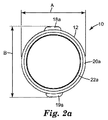
図1に示す実施形態では、本体は、略円筒形状である、すなわち、図2aに示す突出型スペーサ部材以外は、長手方向軸線に対して直交する略円形である断面を有する細長い形状である。当然のことながら、他の形状、例えば、図2bに示すような略楕円形断面を有するスピンドルを本発明に従って使用してもよい。 In the embodiment shown in FIG. 1, the main body has a substantially cylindrical shape, that is, an elongated shape having a cross section that is substantially circular perpendicular to the longitudinal axis, except for the protruding spacer member shown in FIG. 2a. Of course, other shapes may be used in accordance with the present invention, for example, a spindle having a generally elliptical cross-section as shown in FIG. 2b.
スペーサ部材は、第1の突出位置及び第2の非突出位置に構成できる。図1は、スペーサ部材が突出部を有する弾力アーム部の形態である好ましい実施形態を示す。 The spacer member can be configured at a first projecting position and a second non-projecting position. FIG. 1 shows a preferred embodiment in which the spacer member is in the form of a resilient arm having protrusions.
図1及び図2aを参照すると、本体12は、寸法Aの直径を有する略円筒形状である。その第1の、すなわち、突出構成において、突出部18a及び19aは、本体12の表面を越えて突出し、寸法Bを定義する。各スペーサ部材の突出部18a及び19a並びに他の部分は、そのそれぞれの第2の、すなわち、非突出位置に構成された場合、本体12の断面の外形(つまり、寸法A)を越えて実質的に突出しないように本体12の内部に引き寄せられる。場合によっては、本体12の断面の外形の下に押し込められてもよい。
Referring to FIGS. 1 and 2 a, the
典型的には、テープロールは、コアを有する又は有しない、円形の環状コア開口部を有する。本発明に従って、スピンドルは、以下の内径を有するコア開口部を有するテープロールに使用される:(1)非突出位置にスペーサ部材を有するスピンドルの本体の、長手方向軸線と直交する方向の、最大寸法(図1の寸法A)を少なくとも有する内径、及び(2)突出位置にスペーサ部材を有するスピンドルの本体の、長手方向軸線と直交する方向の、最大寸法(図1の寸法B)未満の内径。本発明に従い、スピンドル10に使用できるテープロールのコアの直径は、スピンドル10の寸法Aが最小であり、寸法Bが最大である。そのような関係において、図3及び図4に示すように、テープロール28bがスピンドル上の長手方向の所望の位置に保持され、図3に示されるように、隣接するロールは接触しない。したがって、本発明に従って、隣接するテープロールから干渉を受けずに、どのテープロールからも材料が分配可能である。
Typically, a tape roll has a circular annular core opening with or without a core. In accordance with the present invention, the spindle is used in a tape roll having a core opening having the following inner diameter: (1) Maximum in the direction perpendicular to the longitudinal axis of the body of the spindle having a spacer member in a non-projecting position An inner diameter having at least a dimension (dimension A in FIG. 1), and (2) an inner diameter less than the maximum dimension (dimension B in FIG. 1) in the direction perpendicular to the longitudinal axis of the main body of the spindle having a spacer member at the protruding position. . According to the present invention, the diameter of the core of the tape roll that can be used for the
図2bは、スピンドル110の本体112が楕円形断面、つまり、寸法B1がB2未満である、例示的な代替実施形態を示す。スペーサ部材の突出部118a及び119aが本体112の長手寸法を超えて伸びる、寸法Aとして示される、突出位置として構成可能である。そのようなスピンドルは、本発明に従って、少なくとも寸法B1の直径を有し、かつ寸法A未満の直径を有するコア開口部(例えば、点線で図中に示すテープコア)を有するテープロールに使用できる。スピンドル110は、例えば、端部120aに突出ネック部122aを設けることによって、ディスペンサ(図示せず)に係合するようになっている。
Figure 2b shows the
図1に示す実施形態では、スペーサ部材14aは、スペーサ部材14b及び14cも同様に、本体12と一体化している。スペーサ部材14aは、突出部18aの他、本体12に接続されているアーム部16aを備える。突出部18aを、図示する突出位置から非突出位置に移動又は再構成するために、アーム部16aが屈曲される。アーム部16aは、突出部18aが繰り返し突出位置から非突出位置、及びその逆を、適宜、移動できるように弾性材から形成されることが好ましい。非突出位置へのスペーサ部材の構成は、例えば、手や指により力を直接スペーサ部材に付与して、スペーサ部材を押し込むように圧力を加えることによって達成できる。いくつかの実施形態において、スペーサ部材の突出部は、コア開口部を有するテープロールをスピンドルに対して移動させることによって加えられる横方向の力によって、スペーサ部材の側面に対して力を加えたとき、本体内に引っ込み、非突出構成となるようになっていてもよい。例えば、図1に示す好ましい実施形態では、突出部は、突出位置から非突出位置への構成変更をより多くできるよう、テーパー状の表面を有する。その場合、材料及び構成部品の構成は、スペーサ部材を非突出位置に移動させるために必要とする最小限の横方法の力の大きさが、テープが分配される際に生じる横方向の力の大きさよりも大きいことが好ましい。テープが分配される際に生じる横方向の力の大きさがあまりに大きいと、使用時、テープが分配されると、テープロールの望ましい安定性とスピンドル上の隣接する(複数の)テープロールとの不干渉が損なわれてしまう。
In the embodiment shown in FIG. 1, the
スペーサ部材14aは、抵抗力が付与されない場合、又はそのような力が取り除かれた場合、突出部18aが突出位置に押し出されるような弾性材を含むことが好ましい。例えば、そのようなスピンドルは、突出構成に構成された(複数の)スペーサ部材を有する形状に弾性プラスチックを成形することによって形成することができる。スペーサ部材を非突出構成に構成するために、スペーサ部材に圧力が加えられる。圧力を放つと、スペーサ部材は、復元し、その結果、突出位置にスペーサ部材が構成される。
It is preferable that the
好ましい実施形態では、スピンドル10が弾性があり、耐久性があるプラスチックで製造される。具体的な例として、ポリスチレン及びアクリロニトリル−ブタジエン−スチレン重合体が挙げられる。これにより、スペーサ部材14aが屈曲し、突出部18aを突出位置及び非突出位置に繰り返し再構成でき、同時に、テープロールを数千回、スピンドルを中心に回動でき、コア開口部を有するテープロールの取り付けと取り外しができ、これらが部品であるディスペンサの(もしあれば)組立と解体とに耐えることができる。
In a preferred embodiment, the
いくつかの実施形態(図示しない)において、スペーサ部材は、スペーサ部材を突出位置に押し出す一方、非突出位置に押し込み可能に構成されたバネに搭載されてもよく、その結果、スピンドルにおけるテープロールの取り付け、取り外し、及び位置変更が可能となる。 In some embodiments (not shown), the spacer member may be mounted on a spring configured to push the spacer member into the protruding position while being pushed into the non-projecting position, so that the tape roll of the spindle is Attachment, removal, and position change are possible.
スピンドルの少なくとも一つの端部、いくつかの実施形態では、両方の端部が支持部と係合するように構成される。例えば、図1に示すように、スピンドル10の端部20a及び20bは、突出ネック部22a及び22bをそれぞれ有する。図4に示すように、端部20a及び20bは、ディスペンサ26の壁部24a及び24bにそれぞれ係合する。壁部24a及び24bは、それぞれ支持端部20a及び20bを受容するように構成される。いくつかの実施形態において、例えば、壁部24a及び24bはそれぞれ、スピンドル10を確実に、好ましくは、解放可能に支持するために突出ネック部22及び22bをそれぞれ受容するための好適なサイズの凹部を有する。スピンドル10がディスペンサの支持部に解放可能に搭載される他の実施形態は、当業者ならば容易に理解できるであろう。具体的な例として、U字型ヨーク、スピンドルに係合する支持壁から突出する突出部、例えば、空洞端部に突出する支柱などを挙げることができる。スピンドル及びディスペンサのマウント部は、所望の数のロールを支持したり、テープを分配したり、テープロールを取り除いたり、新しい又は別のテープロールを取り付ける際の動作に耐えるよう、十分強固で頑丈である必要がある。
At least one end of the spindle, in some embodiments, both ends are configured to engage the support. For example, as shown in FIG. 1, the
いくつかの実施形態において、本発明のスピンドルは、単一のスペーサ部材を備える。他の実施形態においては、スピンドルは、スピンドルの長手方向軸線に沿って配置される長手方向の相異なる位置に配置される2つ以上のスペーサ部材を備え、かつ隣接するテープロール間に1つ以上のスペーサ部材を有する1つ又は2つ以上のロールに使用できる。例えば、図1に示すように、スペーサ部材14a、14b、及び14cは、端部20aから徐々に距離を増すように配置されている。
In some embodiments, the spindle of the present invention comprises a single spacer member. In other embodiments, the spindle comprises two or more spacer members disposed at different longitudinal positions disposed along the longitudinal axis of the spindle, and one or more between adjacent tape rolls. It can be used for one or more rolls having a plurality of spacer members. For example, as shown in FIG. 1, the
好ましい実施形態において、スピンドルは、第1のスペーサ部材と同じ、すなわち、長手方向の同一の、即ち、同等の位置に、好ましくは、第1のスペーサ部材からスピンドルの長手方向軸線を真垂直に横切る第2のスペーサ部材を備える。スペーサ部材14aの突出部18aが、他の同様のスペーサ部材(図では非表示)の突出部19aから本体12を隔てて実質的に垂直に配置される、上記のような実施形態が図2に示される。
In a preferred embodiment, the spindle is the same as the first spacer member, i.e., in the same or equivalent position in the longitudinal direction, preferably transversely perpendicular to the longitudinal axis of the spindle from the first spacer member. A second spacer member is provided. An embodiment as described above is shown in FIG. 2 in which the
図3は、テープロール28a、28b、及び28cが搭載されるスピンドル10を備えるディスペンサ26を示す。図3から分かるように、テープロール28bは、その中心に開口部を有する任意のコア32にロール状に巻き取られた材料であるシート30を含む。そのようなテープロールの構成は、従来技術の範囲内である。いくつかの実施形態において、シート材は、例えば、コアがないマンドレルを中心にロール状に巻き取られてもよい。
FIG. 3 shows a dispenser 26 comprising a
図3に戻って、隣接するテープロールは、少なくとも1つのスペーサ部材によって離間される。例えば、テープロール28a及び28bは、スペーサ部材14aの突出部18a及びスピンドル10の反対側のスペーサ部材(本斜視図では非表示)の突出部19aによって離間される。同様に、テープロール28b及び28cは、スペーサ部材14cの突出部18cによって離間される。本構成において、突出部18a及び18cは、それぞれ突出位置に構成される。つまり、突出部18a及び18cは、スピンドル10の本体12の表面から径方向に延びて、テープロールを望ましい離間状態に維持する。本構成において、突出部18b(非表示)は、テープロール28bのコア32の下の非突出位置に構成される。
Returning to FIG. 3, adjacent tape rolls are separated by at least one spacer member. For example, the tape rolls 28a and 28b are separated from each other by a
所望の場合、ロール28b及び28cを取り外して、単一のロールをスピンドルに搭載できるが、その際は、例えば、スペーサ部材14aを使ってロール28aからの離間状態を維持する。又は、ロールの寸法が許せば、同じことをスペーサ部材14bを使って行う。スピンドルにテープロールを取り付ける際、スピンドルがロールの開口部に挿入される、又は、ロールがスピンドルに被さるように配置されるので、ロール及びスピンドルは、スピンドルの長手方向軸線に平行な方向に互い対して移動することになる。本プロセスを簡易にするため、突出部の縁部は、スペーサ部材がスピンドル本体に屈曲してテープロールがスピンドル本体を通り過ぎるように、図1及び図2に示すように、ある程度テーパー状であることが好ましい。
If desired, the
更に、テープディスペンサ26は、所望のテープから所望の量のシート材を容易に切り離すために使用される、切断部材34、例えば、まっすぐな刃を備える。
In addition, the tape dispenser 26 includes a cutting
好ましい実施形態では、第1のテープロールは、シート材が第1のテープロールから分配される際に、テープロールがスピンドル上を長手方向にスライドして隣接する第2のテープロールと干渉接触しないように、少なくとも1つのスペーサ部材によってスピンドル上の所定の位置に保持される。図3では、テープロール28bが2つのスペーサ部材、つまりスペーサ部材14a及び14cによって、長手方向の所定の位置に保持される。これによってもたらされる安定性の向上が、隣接するロール28a及び28c同士の絡みや、又は部分的な解反を伴わず、容易にシート材30がテープロール28bから取り外され、切断部材34によってきれいに切り離すように改善させる。したがって、本体上のスペーサ部材の長手方向の位置は、スピンドル又はスピンドルを組み入れているディスペンサが使用される、テープロールの幅寸法に部分的に基づいて選択されることになる。
In a preferred embodiment, the first tape roll does not interfere with the adjacent second tape roll as the tape roll slides longitudinally on the spindle as the sheet material is dispensed from the first tape roll. As such, it is held in place on the spindle by at least one spacer member. In FIG. 3, the
本発明に従って、テープロール及びスピンドルは、スピンドルがテープロールを自身で支えることができるようにスピンドル本体の有効外径がテープロールの開口部の内径よりも小さくなるように選択される。典型的には、例えば、抵抗がなく又はあったとしても最小の抵抗で、テープロールからシート材の端部を引っ張ることによって付与される回転力だけで、テープロールがスピンドルを中心に自由に回動できることが好ましい。分配動作を中断する際、ロールの回動が停止するように少々の抵抗が望ましい場合もある。これに対し、過剰な抵抗が生じると、思い通りにシート材を分配することが更に難しくなり、シート材が、破れたり、不必要に伸びきってしまったりするなど、シート材の材質が落ちる場合がある。いくつかの実施形態において、テープロールがぐらつくなどせずにスピンドルを中心に自由にスピンできるようにテープロールの内径がスピンドルの外径よりわずかだけ大きい。当業者なら理解できるように、スピンドルとテープロールとの望ましい摩擦関係は、望ましい特性を発揮する相性がよい材質を選択すること、又は部品処理を施すこと、例えば、適当な摩擦調整コーティングを塗布することによって、達成できる。 In accordance with the present invention, the tape roll and spindle are selected such that the effective outer diameter of the spindle body is smaller than the inner diameter of the opening of the tape roll so that the spindle can support the tape roll itself. Typically, for example, the tape roll is free to rotate about the spindle with only the rotational force applied by pulling the edge of the sheet material from the tape roll with minimal or no resistance. Preferably it can be moved. When interrupting the dispensing operation, a small amount of resistance may be desirable so that the roll rotation stops. On the other hand, if excessive resistance occurs, it becomes more difficult to distribute the sheet material as expected, and the sheet material may be damaged, such as tearing or unnecessarily stretching. is there. In some embodiments, the inner diameter of the tape roll is slightly larger than the outer diameter of the spindle so that the tape roll can spin freely around the spindle without wobbling or the like. As will be appreciated by those skilled in the art, the desired frictional relationship between the spindle and the tape roll can be selected by selecting a compatible material that exhibits the desired properties, or by applying component processing, eg, applying a suitable friction modifying coating. Can be achieved.
本発明は、様々な種類のシート材のテープロールで使用できる。シート材は、接着性があってもなくてもよく、実質的に連続性があり、開口部を有しても良く、平坦でもよく、構造化面等を有してもよい。具体的な例として、紙、プラスチック、金属フィルム、ウェブ、シート等を挙げることができる。 The present invention can be used with tape rolls of various types of sheet materials. The sheet material may or may not be adhesive, is substantially continuous, may have an opening, may be flat, may have a structured surface, and the like. Specific examples include paper, plastic, metal film, web, sheet and the like.
本発明の1つの利点は、スピンドル上の長手方向の相異なる位置に少なくとも1つの、及び好ましくは、2つ以上のスペーサ部材を備える単一のスピンドル装置、又はそのようなスピンドルを備えるディスペンサを、異なる幅を有する様々なテープロールに有利に使用できることである。異なる幅を有するテープロールを、同一のスピンドルを用いて、頻繁にかつ容易に入れ替えることが可能である。例えば、図3に示す実施形態は、本体12が2と1/16インチ(5.2センチ)の長さであり、突出部18a及び18cが端部20a及び20bからそれぞれ約5/8インチ(1.6センチ)離間しており、突出部18a及び18cが互いに約5/8インチ(1.6センチ)離間しており、突出部18bが端部20a及び20bから約1インチ(2.5センチ)離間している場合、例えば、1つ、2つ又は3つの1/2インチ(1.3センチ)のテープロール、1つ又は2つの1インチ(2.5センチ)のロール、1つの2インチ(5.1センチ)のロール、又は1つの1インチ(2.5センチ)のロールを有する1つの1/2インチ(1.3センチ)のロールに効果的に使用できる。
One advantage of the present invention is that a single spindle device comprising at least one and preferably two or more spacer members at different longitudinal positions on the spindle, or a dispenser comprising such a spindle, It can be advantageously used for various tape rolls having different widths. Tape rolls having different widths can be replaced frequently and easily using the same spindle. For example, in the embodiment shown in FIG. 3, the
本発明は、円形のコア開口部を有するテープロールを、スピンドルの端部を越えてスライドさせ、更に、(i)第1のスペーサ部材を越えてスライドさせ、及び/又は(ii)その突出位置にある第1のスペーサ部材までスライドさせることを含む、テープディスペンサを組み立てる方法を提供する。本発明に従って、いくつかの実施形態において、本方法は、第1のテープロールを第1のスペーサ部材を越えてスライドさせることを含み、円形のコア開口部を有する第2のテープロールをスピンドルを越えて第1のスペーサ部材に対してスライドさせることを更に含みえ、前記テープロールは、突出位置にある少なくとも第1のスペーサ部材によって離間される。 The present invention allows a tape roll having a circular core opening to slide beyond the end of the spindle, and (i) to slide beyond the first spacer member and / or (ii) its protruding position. A method of assembling a tape dispenser is provided that includes sliding the first spacer member to In accordance with the present invention, in some embodiments, the method includes sliding a first tape roll over a first spacer member, and a second tape roll having a circular core opening is mounted on the spindle. Slid over and against the first spacer member, the tape roll being spaced apart by at least the first spacer member in a protruding position.
本発明は、コア開口部を有するテープロールからテープを分配する方法であって、テープロールが本明細書に記載のスピンドルに搭載され、例えば、テープの端部を引っ張り、テープの一部をテープロールから繰り出して、その後、例えば、ディスペンサの切断部材を横切ってテープの一部を引っ張る等によって切り離して、テープの一部を典型的にはロール部から切断することによって、テープが分配される際に、スピンドルを中心に回動する、方法を提供する。いくつかの実施形態において、スピンドルは、第1のテープロール及び第2のテープロールを自身に搭載することになり、該テープロールは、該第1のテープロールが該スピンドルを中心に回動するとき、例えば、テープがスピンドルから分配されるとき、第1のテープロールが第2のテープロールに実質的に接触しないように突出位置にある第1のスペーサ部材によって離間される。 The present invention is a method for dispensing tape from a tape roll having a core opening, wherein the tape roll is mounted on a spindle as described herein, for example, pulling the end of the tape and part of the tape to the tape When the tape is dispensed by unwinding it from the roll and then separating it, for example by pulling a part of the tape across the cutting member of the dispenser, etc. And a method of rotating about the spindle. In some embodiments, the spindle will mount a first tape roll and a second tape roll on it, the tape roll rotating about the spindle. Sometimes, for example, when the tape is dispensed from the spindle, the first tape roll is separated by the first spacer member in the protruding position so that it does not substantially contact the second tape roll.
本明細書及び添付の「特許請求の範囲」において使用されるとき、単数形「a」、「an」、及び「the」は、その内容について別段の明確な指示がない限り、複数の指示対象を包含する。本明細書及び添付特許請求の範囲内にて使用される場合、用語「又は」は、別段の明確な指示がない限り、一般的に「及び/又は」を含む意味で用いられる。 As used herein and in the appended claims, the singular forms “a”, “an”, and “the” refer to a plurality of referents unless the content clearly dictates otherwise. Is included. As used herein and in the appended claims, the term “or” is generally employed in its sense including “and / or” unless the content clearly dictates otherwise.
添付図面を参照しながら、本発明を好ましい実施形態と関連付けて完全に説明したが、様々な変更及び修正が当業者に明らかであることに留意されたい。そのような変更及び修正は、添付された特許請求の範囲によって定められるような本発明の範囲から逸脱しない限り、これに含まれるものと理解すべきである。本明細書に引用される全ての特許、特許書類、及び刊行物の完全な開示は、参照によりそれら全体が組み込まれる。 Although the present invention has been fully described in connection with the preferred embodiments with reference to the accompanying drawings, it should be noted that various changes and modifications will be apparent to those skilled in the art. Such changes and modifications are to be understood as being included herein without departing from the scope of the present invention as defined by the appended claims. The complete disclosure of all patents, patent documents, and publications cited herein are incorporated by reference in their entirety.
Claims (6)
Applications Claiming Priority (3)
| Application Number | Priority Date | Filing Date | Title |
|---|---|---|---|
| US201161576809P | 2011-12-16 | 2011-12-16 | |
| US61/576,809 | 2011-12-16 | ||
| PCT/US2012/069694 WO2013090687A1 (en) | 2011-12-16 | 2012-12-14 | Spindle and dispenser for roll products and methods for making and using same |
Publications (3)
| Publication Number | Publication Date |
|---|---|
| JP2015500193A JP2015500193A (en) | 2015-01-05 |
| JP2015500193A5 JP2015500193A5 (en) | 2016-02-04 |
| JP6082754B2 true JP6082754B2 (en) | 2017-02-15 |
Family
ID=47520271
Family Applications (1)
| Application Number | Title | Priority Date | Filing Date |
|---|---|---|---|
| JP2014547473A Expired - Fee Related JP6082754B2 (en) | 2011-12-16 | 2012-12-14 | Spindle and dispenser for roll products, and method for producing and using the same |
Country Status (7)
| Country | Link |
|---|---|
| US (1) | US9517908B2 (en) |
| EP (1) | EP2791037B1 (en) |
| JP (1) | JP6082754B2 (en) |
| KR (1) | KR101918134B1 (en) |
| CN (1) | CN104053619B (en) |
| TW (1) | TWI594939B (en) |
| WO (1) | WO2013090687A1 (en) |
Families Citing this family (3)
| Publication number | Priority date | Publication date | Assignee | Title |
|---|---|---|---|---|
| USD833492S1 (en) * | 2017-03-31 | 2018-11-13 | Inteplast Group Corporation | Film dispenser for use with coreless film roll |
| WO2023282468A1 (en) * | 2021-07-05 | 2023-01-12 | 박기항 | Inertial rotation limiting-type roll dispenser |
| KR102336277B1 (en) * | 2021-07-05 | 2021-12-09 | 박기항 | Strap dispenser and main frame used therefor |
Family Cites Families (34)
| Publication number | Priority date | Publication date | Assignee | Title |
|---|---|---|---|---|
| US634589A (en) | 1899-02-21 | 1899-10-10 | James Edwin Russell | Cabinet or laces, &c. |
| US2177627A (en) | 1933-06-10 | 1939-10-31 | Minnesota Mining & Mfg | Adhesive sheeting |
| US2350369A (en) | 1940-10-07 | 1944-06-06 | Minnesota Mining & Mfg | Tape roll and core |
| US2352445A (en) | 1943-07-07 | 1944-06-27 | Arthur S Pinckney | Device for dispensing strip material |
| US2370821A (en) | 1943-10-15 | 1945-03-06 | Harold R Stott | Paper roll holder |
| US2424486A (en) | 1944-09-29 | 1947-07-22 | Kendall & Co | Pressure-sensitive adhesive tape dispenser |
| US2772774A (en) | 1953-03-19 | 1956-12-04 | Minnesota Mining & Mfg | Tape roll and core |
| US3635383A (en) * | 1969-10-22 | 1972-01-18 | Bulman Mfg Co Inc E O | Tape dispenser for multiple rolls |
| US3768713A (en) | 1971-11-08 | 1973-10-30 | Bulman E Mfg Co Inc | Multiple roll tape dispenser |
| JPS5452490U (en) * | 1977-09-19 | 1979-04-11 | ||
| US4625901A (en) | 1985-10-04 | 1986-12-02 | Adelizi Nicholas J | Multi-blade tape dispenser |
| JPH02108938A (en) | 1988-10-18 | 1990-04-20 | Nippon Denso Co Ltd | Detector for internal pressure of crank chamber |
| US5374008A (en) | 1990-01-16 | 1994-12-20 | Barr, Inc. | Spindle for a rolled material dispenser |
| GB9017620D0 (en) | 1990-08-10 | 1990-09-26 | Wyant And Company Limited | Paper towel dispenser(with brake) |
| JPH0465237U (en) * | 1990-10-19 | 1992-06-05 | ||
| US5624025A (en) | 1995-11-27 | 1997-04-29 | Hixon; Theodore | Multipurpose toilet tissue dispenser |
| FR2750969B1 (en) * | 1996-07-12 | 1998-11-20 | Jamont N V | DISPENSER FOR ROLL OF MATERIAL IN ROLL WITHOUT CHUCK COMPRISING AN IMPROVED SUPPORT ROD |
| USD399257S (en) | 1997-10-31 | 1998-10-06 | Jow-Lin Tang | Tape dispenser |
| AUPP246498A0 (en) | 1998-03-19 | 1998-04-09 | Great Western Corporation Pty Ltd | Apparatus/method for reforming cultivation rows |
| JP2000007211A (en) * | 1998-06-22 | 2000-01-11 | Marujiyuu Kasei Kk | Desk type tape holder |
| USD448415S1 (en) | 2001-02-22 | 2001-09-25 | Harrison Huang | Adhesive tape dispenser |
| USD470815S1 (en) | 2002-02-01 | 2003-02-25 | All Rite Products, Inc. | Seat cover and storage compartment for recreational vehicle |
| US6729512B1 (en) * | 2002-02-12 | 2004-05-04 | James Bruce Leighton | Ribbon dispenser |
| USD470181S1 (en) | 2002-04-25 | 2003-02-11 | Kudos Finder Trading Co., Ltd. | Dispenser for plural adhesive tapes |
| US7290733B2 (en) | 2002-12-31 | 2007-11-06 | Lifetime Brands, Inc. | Dispenser for rolled materials |
| US6974060B2 (en) | 2003-03-18 | 2005-12-13 | Bel-Art Products, Inc. | Multiple roll tape dispenser |
| US6913178B2 (en) | 2003-05-08 | 2005-07-05 | Harrison Huang | Tape dispenser for installation of multi-roll |
| JPWO2004103870A1 (en) * | 2003-05-26 | 2006-07-20 | 有限会社 田辺精機 | Adhesive tape for belt, seat belt, adhesive tape feeding device, and method for applying adhesive tape to seat belt using the same |
| JP4326880B2 (en) * | 2003-08-25 | 2009-09-09 | 株式会社はくぶん | Tape cutter |
| USD504155S1 (en) | 2004-04-14 | 2005-04-19 | 3M Innovative Properties Company | Dual roll desktop tape dispenser |
| US7222817B2 (en) * | 2004-10-18 | 2007-05-29 | Stringer Claude A | Cart handle cover system |
| USD524376S1 (en) | 2005-02-28 | 2006-07-04 | Flynn Garry L | Tape caddy |
| JP2008207821A (en) | 2007-02-23 | 2008-09-11 | Fujitsu Ltd | Carrier tape, electronic component storage body and transportation method of electronic component |
| JP2012240835A (en) * | 2011-05-24 | 2012-12-10 | Sato Knowledge & Intellectual Property Institute | Paper support mechanism of printer |
-
2012
- 2012-12-14 CN CN201280061284.4A patent/CN104053619B/en not_active Expired - Fee Related
- 2012-12-14 TW TW101147643A patent/TWI594939B/en active
- 2012-12-14 WO PCT/US2012/069694 patent/WO2013090687A1/en active Application Filing
- 2012-12-14 US US14/363,246 patent/US9517908B2/en not_active Expired - Fee Related
- 2012-12-14 EP EP12812458.3A patent/EP2791037B1/en not_active Not-in-force
- 2012-12-14 JP JP2014547473A patent/JP6082754B2/en not_active Expired - Fee Related
- 2012-12-14 KR KR1020147019178A patent/KR101918134B1/en active IP Right Grant
Also Published As
| Publication number | Publication date |
|---|---|
| EP2791037A1 (en) | 2014-10-22 |
| KR101918134B1 (en) | 2018-11-13 |
| KR20140104483A (en) | 2014-08-28 |
| CN104053619B (en) | 2016-06-08 |
| US9517908B2 (en) | 2016-12-13 |
| TW201336763A (en) | 2013-09-16 |
| TWI594939B (en) | 2017-08-11 |
| CN104053619A (en) | 2014-09-17 |
| US20140332617A1 (en) | 2014-11-13 |
| JP2015500193A (en) | 2015-01-05 |
| EP2791037B1 (en) | 2016-03-02 |
| WO2013090687A1 (en) | 2013-06-20 |
Similar Documents
| Publication | Publication Date | Title |
|---|---|---|
| US10280036B2 (en) | Braking wrap dispenser | |
| US6612474B2 (en) | Hand-held tape dispenser with brake mechanism | |
| US11311152B2 (en) | Spindle assembly for sheet product dispensers | |
| CA2984277C (en) | Brake assembly for a tape dispenser | |
| JP6082754B2 (en) | Spindle and dispenser for roll products, and method for producing and using the same | |
| CA1082656A (en) | Sliding-pivoting roll support in a strip dispenser with a tearing edge | |
| US20130264016A1 (en) | Locking tape dispenser | |
| CA2984273A1 (en) | Brake assembly for a tape dispenser | |
| US7175062B2 (en) | Hand-held tape dispenser having brake and flexible side | |
| KR101868994B1 (en) | Tape cutting length adjustable dispenser | |
| CA2984270A1 (en) | Brake assembly for a tape dispenser | |
| US7322543B2 (en) | Party streamer dispenser | |
| US10336566B2 (en) | Feed tape dispenser | |
| US10005633B2 (en) | Dispensers | |
| JP2004504996A (en) | Dispenser with cutting blade / feed roll separation assembly | |
| CA3027569A1 (en) | Improved feed tape dispenser | |
| EP1388517B1 (en) | Roll of sheet material, particularly paper, and relative manufacturing method | |
| CA2432933C (en) | Hand-held tape dispenser with integrated brake mechanism | |
| WO2019148168A2 (en) | Adhesive tape dispenser with tape alignment mechanism |
Legal Events
| Date | Code | Title | Description |
|---|---|---|---|
| A521 | Request for written amendment filed |
Free format text: JAPANESE INTERMEDIATE CODE: A523 Effective date: 20151209 |
|
| A621 | Written request for application examination |
Free format text: JAPANESE INTERMEDIATE CODE: A621 Effective date: 20151209 |
|
| A977 | Report on retrieval |
Free format text: JAPANESE INTERMEDIATE CODE: A971007 Effective date: 20160728 |
|
| A131 | Notification of reasons for refusal |
Free format text: JAPANESE INTERMEDIATE CODE: A131 Effective date: 20160802 |
|
| A521 | Request for written amendment filed |
Free format text: JAPANESE INTERMEDIATE CODE: A523 Effective date: 20161028 |
|
| TRDD | Decision of grant or rejection written | ||
| A01 | Written decision to grant a patent or to grant a registration (utility model) |
Free format text: JAPANESE INTERMEDIATE CODE: A01 Effective date: 20170104 |
|
| A61 | First payment of annual fees (during grant procedure) |
Free format text: JAPANESE INTERMEDIATE CODE: A61 Effective date: 20170123 |
|
| R150 | Certificate of patent or registration of utility model |
Ref document number: 6082754 Country of ref document: JP Free format text: JAPANESE INTERMEDIATE CODE: R150 |
|
| R250 | Receipt of annual fees |
Free format text: JAPANESE INTERMEDIATE CODE: R250 |
|
| R250 | Receipt of annual fees |
Free format text: JAPANESE INTERMEDIATE CODE: R250 |
|
| R250 | Receipt of annual fees |
Free format text: JAPANESE INTERMEDIATE CODE: R250 |
|
| LAPS | Cancellation because of no payment of annual fees |