JP6077414B2 - Wall fixing bracket - Google Patents
Wall fixing bracket Download PDFInfo
- Publication number
- JP6077414B2 JP6077414B2 JP2013157979A JP2013157979A JP6077414B2 JP 6077414 B2 JP6077414 B2 JP 6077414B2 JP 2013157979 A JP2013157979 A JP 2013157979A JP 2013157979 A JP2013157979 A JP 2013157979A JP 6077414 B2 JP6077414 B2 JP 6077414B2
- Authority
- JP
- Japan
- Prior art keywords
- wall
- groove
- piece
- housing
- fixing
- Prior art date
- Legal status (The legal status is an assumption and is not a legal conclusion. Google has not performed a legal analysis and makes no representation as to the accuracy of the status listed.)
- Expired - Fee Related
Links
Images


Description
本発明は、筐体と壁とを固定する壁固定金具の構造に関する。 The present invention relates to a structure of a wall fixing bracket that fixes a housing and a wall.
従来よりこの種の、例えば貯湯式給湯機の筐体と壁を固定する壁固定金具はL字型の形状をしており、前記L字の長い部分には長手方向にのびる長穴が開口されている。そして、前記壁固定金具の短い部分と壁とをネジ等の固定具で固定し、長穴を介して長い部分と筐体の側面または天面とを前記固定具で固定するようにしているため、前記筐体設置時に筐体と壁との距離が適宜変更しても、長穴寸法分だけ前記固定具の螺着位置を変更することで確実に固定することができるものであった。 Conventionally, for example, a wall fixing bracket for fixing a housing and a wall of a hot water storage type water heater has an L-shaped shape, and a long hole extending in the longitudinal direction is opened in a long portion of the L shape. ing. And since the short part and the wall of the wall fixing bracket are fixed with a fixing tool such as a screw, the long part and the side surface or the top surface of the housing are fixed with the fixing tool through a long hole. Even when the distance between the housing and the wall is changed as appropriate when the housing is installed, it can be reliably fixed by changing the screwing position of the fixing tool by the length of the long hole.
ところが、この従来のものでは、前記筐体の側面または天面と壁とを前記長穴を介して固定している前記固定具が地震などの大きな揺れで緩んでしまったときに、前記固定具で固定しきれなくなった筐体が長穴寸法分の範囲を揺れてしまうため、筐体の揺れを抑制することができなかった。特に、例えば貯湯式給湯機のように重量のあるものであった場合は、貯湯式給湯機の脚の部分に負担がかかり、変形などの破損をしてしまうという問題があった。 However, in this conventional device, when the fixture that fixes the side surface or the top surface and the wall of the housing via the elongated hole is loosened by a large shake such as an earthquake, the fixture Since the housing that could not be fixed by the rocking range of the slot size, the shaking of the housing could not be suppressed. In particular, in the case of a heavy item such as a hot water storage type hot water heater, there is a problem that a leg portion of the hot water type hot water heater is burdened and damaged such as deformation.
本発明は上記課題を解決するため、側面をもつ略直方体の筐体と壁の間を固定する、長い一片と短い他片とを有したL字形状で、前記一片の長手方向に水平に延びる長穴が開口された壁固定金具において、前記筐体と前記壁固定金具を螺着する固定具を設け、前記壁固定金具は、前記長穴に直交する方向に前記長穴から連続して開口された溝部を有し、前記一片を前記筐体の側面に前記長穴を介して前記固定具で固定し、前記他片を前記壁に固定し、前記固定具の締結力を超えて前記固定具がスライドしてしまった場合に前記固定具が前記溝部に入り込めるようにした。 Since the present invention is to solve the above problems, fixed between the substantially rectangular parallelepiped housing and the wall having a side surface, a long piece and in L-shape and a short other piece, horizontally in the longitudinal direction of the piece In the wall fixing bracket having an elongated slot opened, a fixing tool for screwing the housing and the wall fixing bracket is provided, and the wall fixing bracket is continuous from the slot in a direction perpendicular to the slot. apertured have grooves, the piece was fixed with the fixture through the elongated hole on the side surface of the housing, fixing the other piece to the wall, the beyond the fastening force of the fastener When the fixture has slid, the fixture can enter the groove .
また、前記一片は、平行に並んだ少なくとも上側と下側の2本の前記長穴をもち、前記長穴に開口された前記溝部は、少なくとも1つの前記溝部の位置を長手方向に平行移動させて、上側と下側の前記溝部をずらして配置した。 The one piece has at least two upper and lower elongated holes arranged in parallel, and the groove opening in the elongated hole translates the position of at least one groove in the longitudinal direction. Thus, the upper and lower groove portions were shifted from each other.
また、前記溝部は、幅狭の入り口部分と、前記入り口から連続して奥まった位置にあり、前記長手方向に水平に延びる、前記入り口部分の幅よりも広い左右対称の長溝を設けた。 Moreover, the said groove part was provided in the narrow entrance part and the position which continued in the back from the said entrance, and was extended in the longitudinal direction horizontally, and the symmetrical long groove | channel wider than the width | variety of the said entrance part was provided.
本発明によれば、地震等の揺れで筐体が傾いたときに、ネジ等の固定具が長穴に連続して開口された溝部に引っかかり、長穴の端までスライドするほど揺れてしまうのを抑制し、筐体の転倒や筐体および筐体脚部の破損や変形を防止することができる。 According to the present invention, when the housing is tilted due to a shake such as an earthquake, a fixing tool such as a screw is caught in a groove portion that is continuously opened to the long hole and swings as it slides to the end of the long hole. Can be prevented, and the casing can be prevented from falling and the casing and the casing leg from being damaged or deformed.
次に、本発明の第1の実施形態の筐体と壁とを固定する壁固定金具の構成について図面にもとづいて説明する。
図1は筐体と壁を側面から見た図である。1は略直方体形状の筐体であり、例えば図示しない湯を貯湯する貯湯タンクを内側に備えた貯湯式給湯機の筐体である。2は貯湯式給湯機の筐体1を支えると共に図示しないアンカーボルトによって設置面に固定される脚部である。3は貯湯式給湯機の筐体1を設置する家屋等の壁である。4は貯湯式給湯機の筐体1の側面または天面と壁3を固定するL字型の壁固定金具、5は貯湯式給湯機の筐体1と前記L字型の壁固定金具4とを螺着したネジ等の固定具である。
Next, the structure of the wall fixing metal fixture which fixes the housing | casing and wall of the 1st Embodiment of this invention is demonstrated based on drawing.
FIG. 1 is a side view of the housing and the wall.
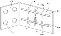
図2、図3で示すように、壁固定金具4は、貯湯式給湯機の筐体1と固定される長い一片4aと、壁3と固定される短い他片4bとを有したL字状をしており、壁固定金具の長い一片4aには長手方向にそって2本の平行な長穴6が開口され、短い他片4bには壁固定用の穴部7が複数開口されている。また、長穴6の長手方向に直交する方向には、長穴6から連続して開口された溝部8が上下対称に複数設けられている。ここでは長穴6の長手方向の中心よりに上下3箇所ずつ計6つの溝部8が設けられている。溝部8の幅は固定具5の軸直径よりわずかに大きく、かつネジ頭径より小さく、長穴6の幅と略同寸としており、溝部8の深さは固定具5の軸直径の0.6〜1.5倍程度の深さとしている。
As shown in FIGS. 2 and 3, the
そして筐体の設置時には図4に示すように、家屋の壁3と壁固定金具4との短い他片4bを壁固定用の穴部7を介してネジ等で固定し、壁固定金具4の長い一片4aと貯湯式給湯機の筐体1とを長穴6を介して固定具5で固定する。そのとき、貯湯式給湯機の筐体1の設置位置は、長穴6の寸法範囲分だけ家屋の壁3との距離を適宜移動させることができるため、設置場所によって壁3との距離が異なっていても確実に固定することができる。
When the housing is installed, as shown in FIG. 4, the short
また、地震等の大きな揺れで、揺れの強さが固定具の締結力を超えると、貯湯式給湯機の筐体1は長穴6の寸法分の範囲をスライドする。しかし、長穴6が溝部8を持つ形状をしているので、図5で示すようにスライド時に固定具5が溝部8に引っかかり、貯湯式給湯機の筐体1が長穴6の端までスライドしてしまうのを抑制することができる。
Further, when the strength of the shaking exceeds the fastening force of the fixture due to a large shaking such as an earthquake, the
このように、固定具5が溝部8に引っかかることによって、貯湯式給湯機の筐体1が大きく傾くことを抑制し、筐体1の脚部2に負担がかかることで起きる脚部2の破損や変形などを防止することができる。
In this way, when the
次に壁固定金具4の溝部8の位置を変更した第2の実施形態について図5に基づいて説明する。ここでは、第1の実施形態第と同一のものは同一の符号を付してその説明を省略する。
Next, 2nd Embodiment which changed the position of the
ここで図5に示すように上側の長穴を6a、下側の長穴を6b、上側の長穴6aに等間隔で複数設けられた上下対称の溝部を8a、下側の長穴6bに等間隔で複数設けられた上下対称の溝部を8b、上側の溝部8aの垂直方向の中心線をA、下側の溝部8bの垂直方向の中心線をBと呼ぶこととする。 Here, as shown in FIG. 5, the upper slot 6a, the lower slot 6b, a plurality of vertically symmetrical grooves provided in the upper slot 6a at equal intervals are formed 8a, and the lower slot 6b. The vertically symmetric groove portions provided at equal intervals are referred to as 8b, the vertical center line of the upper groove portion 8a is referred to as A, and the vertical center line of the lower groove portion 8b is referred to as B.
そして、溝部8aと溝部8bとは、中心線Aと中心線Bとの間に壁固定金具4の距離Cだけずらした位置に設けている。この距離Cは、筐体1が壁固定金具4の長手方向に1°から数°傾いた際に、筐体1に螺着される2本の固定具5が傾きの支点を軸に回転移動した場合の、上側と下側の固定具5間の水平方向の距離に基づいて適宜決められるものである。
And the groove part 8a and the groove part 8b are provided in the position shifted by the distance C of the
このように、溝部8aと溝部8bとを距離Cだけずらして設けているため、地震等の大きな揺れのときに筐体1が傾いてしまったときでも固定具5が溝部8に無理なく入ることができることで、筐体1が大きく傾くことを抑制し、筐体1の脚部2に負担がかかることで起きる脚部2の破損や変形などを防止することができる。
As described above, since the groove 8a and the groove 8b are provided by being shifted by the distance C, the
なお、第1、第2の実施形態では、溝部8の形状をU字状で説明したが、これに限定されるものではなく、例えばV字状や四角状でもよいものとする。
In the first and second embodiments, the shape of the
次に壁固定金具4の溝部8の形状を変更した第3の実施形態について図6に基づいて説明する。ここでは、第1の実施形態と同一のものは同一の符号を付してその説明を省略する。
Next, 3rd Embodiment which changed the shape of the
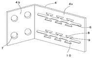
この第3の実施形態の溝部8は、幅狭の入り口9と、入り口9から連続して奥まった位置で、壁固定金具4の長い一片4aの長手方向に左右対称に広がる長溝10とを有しているものである。
The
入り口9の形はテーパー状になっていて、長穴6付近の開口部分は広く、奥に行くほどに狭くなる形状をしている。入り口9の開口部分の幅は固定具5の軸直径ネジ頭径よりも小さく、長穴6の幅よりは大きい。長溝10に近い部分の幅は固定具5の軸直径よりもわずかに大きく、かつネジ頭径よりも小さく長穴6の幅と略同寸としている。これにより、固定具5がスライドして、溝部8に入り込むときに入りやすく抜けにくい形状を作ることができる。
The shape of the
また、長溝10の短手方向の幅も固定具5の軸直径よりもわずかに大きく、かつネジ頭径よりも小さく長穴6の幅と略同寸としていると共に長溝10の長手方向の長さは固定具5の軸直径の1.5〜3倍程度の長さとしている。
Also, the width of the
このように、溝部8を入り口9とその奥に長溝10を設けた構成としているため、長溝10にはまった固定具が出て行きにくい特徴を持ち、地震等の大きな揺れのときに固定具5がスライドして入り口9から奥の長溝10に入り込んだ際、揺れ幅を長溝10の距離分で抑えることができ、上下の揺れに対しても長溝10の出口部分が狭いので固定具5が容易に抜けるのを防ぐことができる。また、筐体1が大きく傾くことを抑制し、筐体1の脚部2に負担がかかることで起きる脚部2の破損や変形などを防止することもできる。
As described above, since the
なお、本発明は第3の実施形態に限定されるものではなく、要旨を変更しない範囲で改変することを妨げるものではなく、例えば、溝部8の形状が湾曲した長溝状であったり、溝の形状が左右対称ではなく片方にだけ延びた形状であったり、入り口9のテーパー部分が逆向きテーパー状またはテーパーなしでも良いものである。
In addition, this invention is not limited to 3rd Embodiment, It does not prevent changing in the range which does not change a summary, For example, the shape of the
また、1から3の実施形態では、例えば、今回の筐体は貯湯式給湯機を例にあげたが、他にも天面及び側面を有した電気温水器や温水ボイラ等でも良いものである。 In the first to third embodiments, for example, the case of this time is a hot water storage type hot water heater, but an electric water heater or a hot water boiler having a top surface and a side surface may be used. .
1 筐体
4 壁固定金具
4a 壁固定金具の一片
4b 壁固定金具の他片
5 ネジ等の固定具
6 長穴
7 壁固定用の穴部
8 溝部
8a 上側の溝部
8b 下側の溝部
9 入り口
10 長溝
DESCRIPTION OF
Claims (3)
Priority Applications (1)
| Application Number | Priority Date | Filing Date | Title |
|---|---|---|---|
| JP2013157979A JP6077414B2 (en) | 2013-07-30 | 2013-07-30 | Wall fixing bracket |
Applications Claiming Priority (1)
| Application Number | Priority Date | Filing Date | Title |
|---|---|---|---|
| JP2013157979A JP6077414B2 (en) | 2013-07-30 | 2013-07-30 | Wall fixing bracket |
Publications (2)
| Publication Number | Publication Date |
|---|---|
| JP2015028402A JP2015028402A (en) | 2015-02-12 |
| JP6077414B2 true JP6077414B2 (en) | 2017-02-08 |
Family
ID=52492181
Family Applications (1)
| Application Number | Title | Priority Date | Filing Date |
|---|---|---|---|
| JP2013157979A Expired - Fee Related JP6077414B2 (en) | 2013-07-30 | 2013-07-30 | Wall fixing bracket |
Country Status (1)
| Country | Link |
|---|---|
| JP (1) | JP6077414B2 (en) |
Cited By (1)
| Publication number | Priority date | Publication date | Assignee | Title |
|---|---|---|---|---|
| KR101910372B1 (en) * | 2017-09-27 | 2019-01-04 | 아주와이어(주) | Electric cable processing guide apparatus using Electron Beam |
Families Citing this family (1)
| Publication number | Priority date | Publication date | Assignee | Title |
|---|---|---|---|---|
| JP6329498B2 (en) * | 2015-02-19 | 2018-05-23 | 株式会社コロナ | Outdoor equipment installation equipment |
Family Cites Families (5)
| Publication number | Priority date | Publication date | Assignee | Title |
|---|---|---|---|---|
| JPS5024038Y1 (en) * | 1968-03-11 | 1975-07-19 | ||
| JPH0614590Y2 (en) * | 1989-03-02 | 1994-04-20 | 有限会社岡安画材 | Picture frame |
| JPH0785350A (en) * | 1993-09-13 | 1995-03-31 | Toshiba Corp | Prevention structure of falling-down of automatic vending machine |
| JPH10323249A (en) * | 1997-05-23 | 1998-12-08 | Hoshizaki Electric Co Ltd | Fall preventive device for assembly type box body |
| JP4912662B2 (en) * | 2005-10-28 | 2012-04-11 | 旭化成ホームズ株式会社 | Furniture / equipment fall prevention fixture and fall prevention fixation method |
-
2013
- 2013-07-30 JP JP2013157979A patent/JP6077414B2/en not_active Expired - Fee Related
Cited By (1)
| Publication number | Priority date | Publication date | Assignee | Title |
|---|---|---|---|---|
| KR101910372B1 (en) * | 2017-09-27 | 2019-01-04 | 아주와이어(주) | Electric cable processing guide apparatus using Electron Beam |
Also Published As
| Publication number | Publication date |
|---|---|
| JP2015028402A (en) | 2015-02-12 |
Similar Documents
| Publication | Publication Date | Title |
|---|---|---|
| AU2013277825A1 (en) | Holding device with a stem part including a fin | |
| US20130011214A1 (en) | Drilling scrwe with compound threads | |
| JP6077414B2 (en) | Wall fixing bracket | |
| KR20160121936A (en) | A Protection Unit for Cable Supporting | |
| KR100947365B1 (en) | Structure For Assembling Sliding Type Of Cable Tray | |
| US8667872B2 (en) | Socket holder | |
| JP6254047B2 (en) | Building exterior louver | |
| JP2015101891A (en) | Fixture | |
| JP5966753B2 (en) | Small portable devices | |
| JP2015137773A (en) | Wall metal fastener | |
| JP6262538B2 (en) | Building structure | |
| JP6099178B1 (en) | Ceiling clip | |
| US20140332647A1 (en) | Coupling device | |
| JP2007260212A (en) | Deflection preventing mechanism of counter | |
| JP2017038451A (en) | Bird damage prevention tool | |
| JP5495214B2 (en) | Pipe holder | |
| JP2011104771A (en) | Hand tool holder | |
| JP4410144B2 (en) | Wiring / piping box and wiring / piping box equipment | |
| CN203729683U (en) | Ground lock dustproof cover | |
| KR100949759B1 (en) | Tool for put on multipurpose | |
| JP2015052421A (en) | Wall fixing metal fitting | |
| JP6593962B2 (en) | Door device | |
| JP2014001587A5 (en) | Closure, unauthorized opening prevention device, and automatic door | |
| KR102119649B1 (en) | Box for vehicle | |
| KR20130007417U (en) | Rack unit for hose |
Legal Events
| Date | Code | Title | Description |
|---|---|---|---|
| A621 | Written request for application examination |
Free format text: JAPANESE INTERMEDIATE CODE: A621 Effective date: 20151222 |
|
| A977 | Report on retrieval |
Free format text: JAPANESE INTERMEDIATE CODE: A971007 Effective date: 20161012 |
|
| A131 | Notification of reasons for refusal |
Free format text: JAPANESE INTERMEDIATE CODE: A131 Effective date: 20161018 |
|
| A521 | Request for written amendment filed |
Free format text: JAPANESE INTERMEDIATE CODE: A523 Effective date: 20161111 |
|
| TRDD | Decision of grant or rejection written | ||
| A01 | Written decision to grant a patent or to grant a registration (utility model) |
Free format text: JAPANESE INTERMEDIATE CODE: A01 Effective date: 20170110 |
|
| A61 | First payment of annual fees (during grant procedure) |
Free format text: JAPANESE INTERMEDIATE CODE: A61 Effective date: 20170112 |
|
| R150 | Certificate of patent or registration of utility model |
Ref document number: 6077414 Country of ref document: JP Free format text: JAPANESE INTERMEDIATE CODE: R150 |
|
| R250 | Receipt of annual fees |
Free format text: JAPANESE INTERMEDIATE CODE: R250 |
|
| R250 | Receipt of annual fees |
Free format text: JAPANESE INTERMEDIATE CODE: R250 |
|
| R250 | Receipt of annual fees |
Free format text: JAPANESE INTERMEDIATE CODE: R250 |
|
| LAPS | Cancellation because of no payment of annual fees |