JP6075813B1 - Light irradiation unit - Google Patents
Light irradiation unit Download PDFInfo
- Publication number
- JP6075813B1 JP6075813B1 JP2016019263A JP2016019263A JP6075813B1 JP 6075813 B1 JP6075813 B1 JP 6075813B1 JP 2016019263 A JP2016019263 A JP 2016019263A JP 2016019263 A JP2016019263 A JP 2016019263A JP 6075813 B1 JP6075813 B1 JP 6075813B1
- Authority
- JP
- Japan
- Prior art keywords
- light emitting
- light
- emitting diodes
- substrate
- trunk line
- Prior art date
- Legal status (The legal status is an assumption and is not a legal conclusion. Google has not performed a legal analysis and makes no representation as to the accuracy of the status listed.)
- Expired - Fee Related
Links
- 239000000758 substrate Substances 0.000 claims abstract description 56
- 238000010586 diagram Methods 0.000 description 11
- 230000008635 plant growth Effects 0.000 description 7
- 230000003287 optical effect Effects 0.000 description 6
- 230000012010 growth Effects 0.000 description 4
- 238000012986 modification Methods 0.000 description 4
- 230000004048 modification Effects 0.000 description 4
- 230000001678 irradiating effect Effects 0.000 description 3
- 238000013461 design Methods 0.000 description 2
- 238000002474 experimental method Methods 0.000 description 2
- 238000011160 research Methods 0.000 description 2
- 241000251468 Actinopterygii Species 0.000 description 1
- RYGMFSIKBFXOCR-UHFFFAOYSA-N Copper Chemical compound [Cu] RYGMFSIKBFXOCR-UHFFFAOYSA-N 0.000 description 1
- 241000195493 Cryptophyta Species 0.000 description 1
- 238000003491 array Methods 0.000 description 1
- 239000011889 copper foil Substances 0.000 description 1
- 239000011159 matrix material Substances 0.000 description 1
- 238000000034 method Methods 0.000 description 1
- 230000002093 peripheral effect Effects 0.000 description 1
- 230000029553 photosynthesis Effects 0.000 description 1
- 238000010672 photosynthesis Methods 0.000 description 1
- 230000005855 radiation Effects 0.000 description 1
- 230000001954 sterilising effect Effects 0.000 description 1
- 239000000126 substance Substances 0.000 description 1
- 239000013589 supplement Substances 0.000 description 1
- 230000001502 supplementing effect Effects 0.000 description 1
Images


Landscapes
- Cultivation Of Plants (AREA)
- Led Device Packages (AREA)
Abstract
【課題】光源サイズ・光質・光量を、容易に調整可能に標準化された光照射装置を得る。【解決手段】表面実装型の複数の発光ダイオード2,3は、矩形状の基板1Aの一方面に、基板1Aの一辺に平行な方向に等間隔に配列され、出力する光の指向角を調整可能なレンズキャップを搭載可能である。支線5,6は、発光ダイオード2のうち、一列に並ぶ発光ダイオード2をそれぞれ直列に接続する。第1の幹線7は、支線5,6それぞれの一方端と電気接続し、Y軸方向に延びている。第2の幹線8は、支線5,6それぞれの他方端と電気接続し、Y軸方向に延びている。第1の外部端子9は、第1の幹線7と外部の電気回路とを電気接続するために第1の幹線7の両端に設けられている。第2の外部端子10は、第2の幹線8と外部の電気回路とを電気接続するために第2の幹線8の両端に設けられている。【選択図】図1A light irradiation apparatus standardized so that light source size, light quality, and light quantity can be easily adjusted is obtained. A plurality of surface mount type light emitting diodes (2) and (3) are arranged on one side of a rectangular substrate (1A) at equal intervals in a direction parallel to one side of the substrate (1A), and the directivity angle of the output light is adjusted. Possible lens caps can be mounted. The branch lines 5 and 6 respectively connect the light emitting diodes 2 arranged in a line among the light emitting diodes 2 in series. The first trunk line 7 is electrically connected to one end of each of the branch lines 5 and 6 and extends in the Y-axis direction. The second trunk line 8 is electrically connected to the other ends of the branch lines 5 and 6 and extends in the Y-axis direction. The first external terminals 9 are provided at both ends of the first trunk line 7 in order to electrically connect the first trunk line 7 and an external electric circuit. The second external terminals 10 are provided at both ends of the second trunk line 8 in order to electrically connect the second trunk line 8 and an external electric circuit. [Selection] Figure 1
Description
本発明は、光照射装置ユニットに関する。 The present invention relates to a light irradiation device unit.
植物工場の栽培用照明装置として用いられ、光合成に適した波長と高光量及びパルス点灯等の発光ダイオードの特徴を活かした光照射装置等が開示されている(例えば、特許文献1乃至3参照)。
A light irradiation device that is used as a lighting device for cultivation in a plant factory and that utilizes the characteristics of light-emitting diodes such as a wavelength suitable for photosynthesis, high light intensity, and pulse lighting is disclosed (for example, see
植物育成のための研究・実証実験・実際に育成が行われる工場では、その目的に応じて光照射装置に求められる光源サイズ・光の波長(以下、「光質」ともいう)・光質毎の物理的光量(以下、「光量」とする)等が様々である。このため、研究、実証実験及び工場ごとに、光照射装置を個別に設計する必要がある。個別設計の労力を軽減するためには、光照射装置をできるだけ標準化し、光源サイズ・光質・光量を求められる量に調整し易くしておくのが望ましい。 In factories where research, demonstration experiments, and actual growth are conducted for plant growth, the light source size, light wavelength (hereinafter also referred to as “light quality”), and light quality required for the light irradiation device according to the purpose There are various physical light quantities (hereinafter referred to as “light quantities”). For this reason, it is necessary to individually design the light irradiation device for each research, demonstration experiment, and factory. In order to reduce the labor of individual design, it is desirable to standardize the light irradiation device as much as possible so that the light source size, light quality, and light quantity can be easily adjusted to required amounts.
植物を育成するための光照射装置の標準化の際の課題として、(A)照射面の光量均一化、(B)配線の煩雑化、(C)複数の発光素子を内蔵した発光ダイオードからの出射光の光軸ずれが上げられる。ここで、照射面とは、光照射装置による光の照射により照らされる面のことであり、植物工場であれば、植物の育成面のことをいう。 Issues when standardizing a light irradiation device for growing plants include (A) uniformizing the amount of light on the irradiated surface, (B) complication of wiring, and (C) exiting from a light emitting diode incorporating a plurality of light emitting elements. The optical axis shift of the incident light is raised. Here, an irradiation surface is a surface illuminated by the light irradiation by a light irradiation apparatus, and if it is a plant factory, it means the growth surface of a plant.
(A)照射面の光量均一化
照射面における光量が均一でない場合には、照射面における植物の育成状態に差が出るため、光照射装置では、光量が照射面において均一であることが要求される。
(A) Uniform light quantity on the irradiated surface If the light quantity on the irradiated surface is not uniform, there will be a difference in the growth state of the plant on the irradiated surface, so the light irradiation device requires that the light quantity be uniform on the irradiated surface. The
(B)配線の煩雑化
植物工場の中には、植物が育成される面が極めて大きいものがあり、大きな面に対応する多数の発光ダイオードが配列された光照射装置が必要になる。発光ダイオードの数が増えれば増えるほど、発光ダイオードに電力を供給するための配線は複雑になる。
(B) Wiring complexity Some plant factories have a very large surface on which plants are grown, and a light irradiation device in which a large number of light-emitting diodes corresponding to the large surface are arranged is required. As the number of light emitting diodes increases, the wiring for supplying power to the light emitting diodes becomes more complicated.
(C)出射光の光軸ずれ
赤、緑、青の各色の発光素子を内蔵するいわゆる3in1の発光ダイオードは、各色の出射光について出射中心角のずれ、いわゆる光軸ずれが生じる。この光軸ずれにより、照射面(植物の育成面)に照射される照射光の光質が場所によって偏るようになる。この偏りは、植物の育成に多大な影響を与える。
(C) Optical axis deviation of emitted light A so-called 3-in-1 light emitting diode incorporating light emitting elements of each color of red, green, and blue has a deviation of an emission center angle, that is, a so-called optical axis deviation, for each color of emitted light. Due to this optical axis shift, the light quality of the irradiation light irradiated on the irradiation surface (plant growth surface) is biased depending on the location. This bias has a great impact on plant growth.
本発明は、上記実情に鑑みてなされたものであり、光源サイズ・光質・光量を容易に調整可能に標準化された光照射装置ユニットを提供することを目的とする。 The present invention has been made in view of the above circumstances, and an object of the present invention is to provide a standardized light irradiation device unit that can easily adjust the light source size, light quality, and light amount.
上記目的を達成するために、本発明の光照射装置ユニットは、
矩形状の基板と、
前記基板の一方面上で、前記基板の外辺に平行な第1の方向に等間隔に配列され、出力する光の指向角を調整可能な凸レンズ状のレンズキャップをそれぞれ搭載可能な複数の表面実装型の発光ダイオードと、
前記発光ダイオードのうち、前記第1の方向に並ぶ発光ダイオードを直列に接続する支線と、
前記支線の一方端と電気接続し、前記基板の外辺に平行な第2の方向に延びる第1の幹線と、
前記支線の他方端と電気接続し、前記第2の方向に延びる第2の幹線と、
前記第1の幹線と外部の電気回路とを電気接続するために前記第1の幹線の両端に設けられた第1の外部端子と、
前記第2の幹線と外部の電気回路とを電気接続するために前記第2の幹線の両端に設けられた第2の外部端子と、
を備え、
前記発光ダイオードには、複数の異なる光質の光を発光する発光素子が実装されており、
前記支線、前記第1の幹線、前記第2の幹線、前記第1の外部端子及び前記第2の外部端子が、前記発光素子の光質毎に設けられ、
前記発光ダイオードに内蔵された複数の発光素子が前記第1の方向に並ぶように、前記発光ダイオード各々が前記基板に配設されており、
前記発光ダイオードは、前記第1の方向に複数列配列され、
前記第1の方向に直交する方向に隣接する発光ダイオードの向きが互いに逆向きとなるように前記発光ダイオードが配置されている。
In order to achieve the above object, the light irradiation device unit of the present invention comprises:
A rectangular substrate;
A plurality of surfaces on which a convex lens-shaped lens cap can be mounted on one surface of the substrate, arranged at equal intervals in a first direction parallel to the outer side of the substrate, and capable of adjusting the directivity angle of the output light. Mountable light emitting diode,
Of the light emitting diodes, branch lines connecting the light emitting diodes arranged in the first direction in series;
A first trunk line electrically connected to one end of the branch line and extending in a second direction parallel to the outer edge of the substrate;
A second trunk line electrically connected to the other end of the branch line and extending in the second direction;
First external terminals provided at both ends of the first main line for electrically connecting the first main line and an external electric circuit;
Second external terminals provided at both ends of the second main line for electrically connecting the second main line and an external electric circuit;
Equipped with a,
The light emitting diode is mounted with a light emitting element that emits light of a plurality of different light qualities,
The branch line, the first trunk line, the second trunk line, the first external terminal and the second external terminal are provided for each light quality of the light emitting element,
Each of the light emitting diodes is disposed on the substrate such that a plurality of light emitting elements incorporated in the light emitting diode are arranged in the first direction,
The light emitting diodes are arranged in a plurality of rows in the first direction,
The light emitting diodes are arranged such that the directions of the light emitting diodes adjacent to each other in the direction orthogonal to the first direction are opposite to each other .
前記支線には、流れる電流を一定に保つ定電流ダイオード又は電気抵抗が挿入されている、
こととしてもよい。
In the branch line, a constant current diode or an electric resistance for keeping a flowing current constant is inserted,
It is good as well.
前記第1の幹線及び前記第2の幹線は、前記基板の他方面に設けられており、
前記第1の幹線及び前記第2の幹線は、スルーホールを介して、前記支線と電気接続されている、
こととしてもよい。
The first trunk line and the second trunk line are provided on the other surface of the substrate,
The first trunk line and the second trunk line are electrically connected to the branch line through a through hole.
It is good as well.
前記基板の他方面には、
前記発光ダイオードが設けられた発光領域の裏側の領域に放熱板が設けられている、
こととしてもよい。
On the other side of the substrate,
A heat sink is provided in a region on the back side of the light emitting region provided with the light emitting diode,
It is good as well.
前記発光ダイオードが同じ側を向くように前記基板が敷き詰められたときに、前記発光ダイオードの配列の中心から端部に向かって、出射光の指向角が狭くなるように、前記発光ダイオードに対してレンズキャップが取り付けられている、
こととしてもよい。
When the light emitting diode is the substrate has been laid so as to face the same side, towards the end from the center of the array of light emitting diodes, as the directivity angle of the output Shako becomes narrow, and with respect to the light emitting diode lenses cap is attached,
It is good as well.
本発明に係る光照射装置ユニットでは、矩形状の基板上に複数の発光ダイオードが等間隔で配列されている。したがって、発光ダイオードが同じ側を向くように基板をその外辺を当接させて敷き詰め、等間隔に配列された様々な光源サイズの光照射装置を得ることができる。 In the light irradiation apparatus unit according to the present invention, a plurality of light emitting diodes are arranged at equal intervals on a rectangular substrate. Therefore, it is possible to obtain light irradiation devices of various light source sizes arranged at equal intervals by spreading the substrate so that the light emitting diodes face the same side with their outer sides in contact with each other.
また、本発明に係る光照射装置ユニットによれば、第1、第2の幹線に接続された第1、第2の外部端子は、第2の方向に延びる第1、第2の幹線の両端に形成されているので、発光ダイオードが同じ側を向くように基板を敷き詰めれば、対応する外部端子を基板間で近接させることができる。したがって、近接した外部端子を電気接続するだけで、簡単に、基板に跨がった発光ダイオードの直列並列回路を構成することができる。この結果、複数のユニットによって形成される光照射装置の回路構成を極めてシンプルなものとすることができる。 Moreover, according to the light irradiation apparatus unit which concerns on this invention, the 1st, 2nd external terminal connected to the 1st, 2nd trunk line is the both ends of the 1st, 2nd trunk line extended in a 2nd direction. Therefore, if the substrates are laid out so that the light emitting diodes face the same side, the corresponding external terminals can be brought close to each other. Therefore, a series-parallel circuit of light-emitting diodes straddling the substrate can be configured simply by electrically connecting adjacent external terminals. As a result, the circuit configuration of the light irradiation apparatus formed by a plurality of units can be made extremely simple.
また、発光ダイオードは、出射する光を調整するレンズキャップを搭載可能であるため、各発光ダイオードで個別に、照射面に照射される光の光質・光量を容易に調整可能となる。例えば、発光ダイオードが配列の中心から端部に向かうにつれて、発光ダイオードから出射される光の指向角が狭くなるようにレンズキャップを装着すれば、照射面の光の光量を均一化することができる。 In addition, since the light emitting diode can be equipped with a lens cap for adjusting the emitted light, the light quality / light quantity of the light irradiated on the irradiation surface can be easily adjusted individually for each light emitting diode. For example, if the lens cap is attached so that the directivity angle of the light emitted from the light emitting diode becomes narrower as the light emitting diode moves from the center of the array to the end, the amount of light on the irradiation surface can be made uniform. .
また、発光ダイオードに異なる光質の光を出射する複数の発光素子を内蔵している場合には、発光ダイオードは、内部の発光素子が配列された向きに配列される。また、発光ダイオードは、隣接するもの同士で発光素子の配列が逆となるように配置される。このようにすれば、隣接する発光ダイオードで、各色の光の出射中心軸のずれを逆向きとし、照射面における光の色の偏りを、隣接する発光ダイオードで相殺することができる。 When a plurality of light emitting elements that emit light of different light qualities are incorporated in the light emitting diode, the light emitting diode is arranged in the direction in which the internal light emitting elements are arranged. Further, the light emitting diodes are arranged so that the arrangement of the light emitting elements is reversed between adjacent ones. In this way, it is possible to reverse the deviation of the emission center axis of light of each color in the adjacent light emitting diodes, and offset the color deviation of the light on the irradiation surface with the adjacent light emitting diodes.
以上の構成を有する光照射装置ユニットを用いて光照射装置を構成すれば、光源サイズ・光質・光量を容易に調整可能に標準化された調整可能な光照射装置を得ることができる。 If the light irradiation device is configured using the light irradiation device unit having the above configuration, an adjustable light irradiation device that is standardized so that the light source size, light quality, and light quantity can be easily adjusted can be obtained.
以下、本発明の実施の形態について、図面を参照して詳細に説明する。 Hereinafter, embodiments of the present invention will be described in detail with reference to the drawings.
実施の形態1.
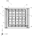
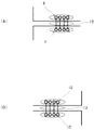
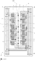
まず、本発明の実施の形態1について説明する。図1に示すように、本実施の形態1に係る光照射装置ユニット100Aは、基板1A上に、発光ダイオード2,3、定電流ダイオード(CCR)13が2次元配列された装置である。光照射装置ユニット100Aは、発光ダイオード2,3が同じ側を向くように基板1Aが敷き詰められた状態で使用される(図2参照)。ここでは、まず、光照射装置ユニット100Aの構成について説明する。
First,
本実施の形態に係る光照射装置ユニット100Aは、1枚の矩形状の基板1Aを中心に構成されている。基板1A上の一方面(+Z側の面)には、複数の発光ダイオード2、3、定電流ダイオード(CCR)13が配列されている。
The light
複数の発光ダイオード2は、基板1AのY軸方向に延びる外辺に平行な方向に等間隔に複数列配列されている。各列の発光ダイオード2の間隔も、列内の発光ダイオード2の間隔と同じである。
The plurality of
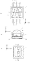
発光ダイオード2は、表面実装型の発光ダイオードである。図3(A)に示すように、発光ダイオード2には、赤色の光を出力する発光素子2R、緑色の発光素子2G、青色の光を出力する発光素子2Bが内蔵されている。すなわち、発光ダイオード2は、3in1の発光ダイオードである。発光ダイオード2は、赤色、青色、緑色の各色の光を出射する。
The
図3(B)に示すように、発光ダイオード2には、発光素子2Rの正負の電極2R1,2R2をはじめ、発光素子2G,2B用の正負の電極が別々に設けられている。このように、発光ダイオード2では、発光素子2R,2G,2Bを別々の電圧で駆動可能となっている。
As shown in FIG. 3B, the
なお、発光ダイオード2に代えて、図3(C)に示すような1in1の発光ダイオード2’を用いてもよい。発光ダイオード2’の発光素子2Aは、発光素子2R,2G,2Bのいずれかである。対応する光質の発光ダイオード2’を各光質に対応する支線5に接続すればよい。
Instead of the
複数の発光ダイオード3は、基板1Aの一辺に平行な方向に等間隔に複数列配列されている。複数の発光ダイオード3は、例えば、遠赤色の光を出射する表面実装型の発光ダイオードである。複数の発光ダイオード3は、発光ダイオード2から出射される光では得られない光質の光を出射するためと、発光ダイオード3の同じ光質の光の光量を増量するために設けられている。
The plurality of
言い換えれば、発光ダイオード2,3は、XY平面上にマトリクス状に等間隔で配列されている。発光ダイオード2はX軸方向及びY軸方向に等間隔で配列され、発光ダイオード3は、発光ダイオード2の間に設けられている。
In other words, the
発光ダイオ−ド2,3には、例えば図3(B)に示すように、それぞれ、レンズキャップ4が搭載されている。レンズキャップ4は、発光ダイオード2,3から出射する光の指向角を調整可能な凸レンズとしての役割を果たす。指向角の選択により、発光ダイオード2,3から出射される放射強度を選択することができる。
As shown in FIG. 3B, for example, a
図4(A)、図4(B)及び図4(C)に示すように、本実施の形態では、3種類のレンズキャップ4が用意されている。図4(A)に示すレンズキャップ4(4A)は、指向角が最も狭くなっており、指向角が狭くなった分、光量が大きくなっている。また、図4(B)に示すレンズキャップ4(4B)は、指向角が、レンズキャップ4(4A)の次に狭くなっている。そして、図4(C)に示すレンズキャップ4(4C)の指向角が一番広くなっている。
As shown in FIGS. 4A, 4B, and 4C, in the present embodiment, three types of
図1に戻り、各発光ダイオード2,3に電力を供給すべく、基板1A上には、配線パターンが形成されている。配線パターンは、支線5,6と、第1の幹線7、第2の幹線8とに分類される。
Returning to FIG. 1, a wiring pattern is formed on the
支線5は、複数の発光ダイオード2のうち、Y軸方向に一列に並ぶ発光ダイオード2をそれぞれ直列に接続する。支線5は、発光ダイオード2の発光素子2R,2G,2B、定電流ダイオード(CCR)13とそれぞれ接続するために一列につき3本設けられている。
The
支線6は、複数の発光ダイオード3のうち、Y軸方向に一列に並ぶ発光ダイオード3、定電流ダイオード(CCR)13をそれぞれ直列に接続する。
The
第1の幹線7、第2の幹線8は、3本の支線5と1本の支線6それぞれに対応してそれぞれ計4本設けられている。第1の幹線7は、Y軸方向に延びており、複数の支線5,6それぞれの一方端(+Y端)と電気接続している。第2の幹線8は、Y軸方向に延びており、複数の支線5,6それぞれの他方端(−Y端)と電気接続している。
A total of four
第1の幹線7のY軸方向両端、かつ、基板1Aの外縁近傍には、第1の外部端子9が設けられている。第1の外部端子9は、第1の幹線7と外部の電気回路とを電気接続するために設けられている。
First
第2の幹線8のY軸方向両端、かつ、基板1Aの外縁近傍には、第2の外部端子10が設けられている。第2の外部端子10は、第2の幹線8と外部の電気回路とを電気接続するために設けられている。
Second
基板1A上には、複数の支線5,6、第1の幹線7、第2の幹線8、第1の外部端子9及び第2の外部端子10が、発光素子の光質(赤、緑、青、遠赤)毎に定電流ダイオード(CCR)13が設けられている。これにより、同じ支線5,6に接続された複数の発光ダイオード2,3を同一電圧で動作させ、各発光素子での発光強度を均等にすることができる。
On the
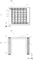
実際には、図5(A)及び図5(B)に示すように、第1の幹線7及び第2の幹線8は、基板1Aの他方面(−Z側の面)に設けられている。第1の幹線7及び第2の幹線8は、スルーホールを介して、複数の支線5,6と電気接続されている。これにより、基板1Aの+Z面の配線パターンを簡素化することができるうえ、基板1AをXY面内に小型化することができる。
Actually, as shown in FIGS. 5A and 5B, the
なお、図5(B)に示すように、基板1Aの−Z側の面には、複数の発光ダイオード2,3、定電流ダイオード(CCR)13が設けられた発光領域の裏側の領域に放熱板11が設けられている。放熱板11には、基板1Aを構成する電気的導通する銅箔面が用いられている。この放熱板11により、発光ダイオード2,3で発生する熱を放熱し易くなっている。これにより、発光ダイオード2,3をより安定して動作させることができる。
As shown in FIG. 5B, heat is radiated to a region on the back side of the light emitting region where a plurality of
図2に示すように、光照射装置ユニット100Aが、複数の発光ダイオード2,3が同じ側を向くように複数の基板1Aが敷き詰められて光照射装置が構成されている。この状態で、図6(A)に示すように、複数の基板1Aにまたがって隣接する第1の外部端子9同士が、ジャンパー線12等で接続される。同様に、図6(B)に示すように、複数の基板1Aにまたがって隣接する第2の外部端子10同士がジャンパー線12等で接続される。これにより、複数の基板1Aに跨がって発光ダイオード2,3、定電流ダイオード(CCR)13が直列回路を並列に接続した回路が構成される。この回路は、各電源回路に接続され、電源回路(不図示)から流れる電流に応じて、発光ダイオード2の各色の発光素子2R,2G,2B及び発光ダイオード3を発光させる。
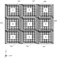
As shown in FIG. 2, the light
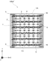
本実施の形態では、各光照射装置ユニット100Aの発光ダイオード2,3に対して、それぞれ場所に応じたレンズキャップ4(4A,4B,4C)が搭載される。図2に示すように、角部に配置された光照射ユニット100A(符号Aが付されている)の発光ダイオード2,3には、レンズキャップ4(4A)が搭載される。また、外辺側の光照射装置ユニット100A(符号Bが付されている)の発光ダイオード2,3には、レンズキャップ4(4B)が搭載される。さらに、中央の光照射装置ユニット100A(符号Cが付されている)の発光ダイオード2,3には、レンズキャップ4(4C)が搭載される。
In the present embodiment, lens caps 4 (4A, 4B, 4C) corresponding to locations are mounted on the
このようにすれば、複数の発光ダイオード2,3の配列の中心から端部に向かって、出射光の指向角が狭くなるように、複数の発光ダイオード2,3に対して、レンズキャップ4(4A,4B,4C)を取り付けることができる。この場合、発光ダイオード2,3は2次元配列されているため、発光ダイオード2,3の配列領域の中心から外周に向かって、レンズキャップ4の指向角が狭くなる。
In this way, the lens cap 4 (with respect to the plurality of
これにより、照射面(植物の育成面)の外周付近の1点の光量に寄与する発光ダイオード2の数は、照射面の中央付近1点の光量に寄与する発光ダイオード2,3の数より少なくなるものの、外周付近の1点に到達する各発光ダイオード2,3の光は、中央の1点に到達する各発光ダイオード2,3の光より強くなるため、照射面外周側の光量が高くなって、照射面全体における光量分布を均一なものとすることができる。このようにすれば、照射面中央の植物に対して、照射面外周の植物の育成が遅れるのを回避することができる。
Thereby, the number of the
また、レンズキャップ4は凸レンズの役割を果たすので、レンズキャップ4を発光ダイオード2,3に取り付けることによって、全体的に照射面における照射光の光量増やすことができる。
Since the
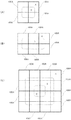
光照射装置ユニット100Aの敷き詰め方は、図2に示すものには限られない。例えば、図7(A)に示すように、光照射装置ユニット100Aを2行2列に配置してもよいし、図7(B)に示すように、光照射装置ユニット100Aを3行2列に配置してもよい。また、図7(C)に示すように、光照射装置ユニット100Aを4行4列に配置してもよい。このように、様々な光源サイズの光照射装置を構成することができる。
The method of spreading the
本実施の形態によれば、配列状態がどのようなものであっても、レンズキャップ4(4A,4B,4C)を用いて、発光ダイオード2,3から出射される出射光の指向角及び強度を調整しているため、光照射装置ユニット100Aの配列に関わらず、発光ダイオード2,3の全体の配列領域の中心から外側に向けて出射する光の指向角が狭くなるように、レンズキャップ4を搭載することができる。
According to the present embodiment, the directivity angle and intensity of the emitted light emitted from the
例えば、図7(A)及び図7(B)に示すように、内側の領域の発光ダイオード2,3に指向角の広いレンズキャップ4(4C)を搭載し、外側の領域の発光ダイオード2,3に指向角の狭いレンズキャップ4(4A)を搭載すれば、照射面での光の光量を均一化することができる。また、図7(C)に示すように、内側の領域の発光ダイオード2,3に指向角の広いレンズキャップ4(4C)を搭載し、その外側の領域の発光ダイオード2,3にレンズキャップ4(4B)を搭載し、最も外側の領域の発光ダイオード2,3にレンズキャップ4(4A)を搭載するようにしてもよい。このようにしても、照射面の光量を均一化することができる。
For example, as shown in FIGS. 7A and 7B, the lens cap 4 (4C) having a wide directivity angle is mounted on the
以上詳細に説明したように、光照射装置ユニット100Aによれば、矩形状の基板1A上に複数の発光ダイオード2,3が等間隔に2次元配列されて形成されている。したがって、複数の発光ダイオード2,3が同じ側を向くように基板1Aを敷き詰めれば、所望の光源サイズの光照射装置を得ることができる。
As described above in detail, according to the light
また、光照射装置ユニット100Aによれば、第1、第2の幹線7,8に接続された第1、第2の外部端子9,10は、Y軸方向に延びる第1、第2の幹線7,8の両端に接続されているので、複数の発光ダイオード2,3、定電流ダイオード(CCR)13が同じ側を向くように基板1Aを敷き詰めれば、第1、第2の外部端子9,10を基板1A間で近接させることができる。したがって、近接した第1、第2の外部端子9,10を電気接続するだけで、簡単に、基板1Aに跨がった発光ダイオード2,3の直列並列回路を構成することができる。この結果、複数の光照射装置ユニット100Aによって形成される光照射装置の回路構成を極めてシンプルなものとすることができる。
Further, according to the light
また、各発光ダイオード2,3は、出射する光を集光するレンズキャップ4(4A,4B,4C)を搭載可能であるため、各発光ダイオード2,3で個別に、照射面に照射される光質・光量を容易に調整可能となる。本実施の形態では、発光ダイオード2,3が配列の中心から端部に向かうにつれて、発光ダイオード2,3から出射される光の指向角が狭くなるようにレンズキャップを装着するので、照射面の光の光量を均一化することができる。
Further, since each of the
なお、図8には、光照射装置ユニット100Aの変形例である光照射装置ユニット100Bが示されている。光照射装置ユニット100A’では、支線5,6はX軸方向に延びており、この方向で発光ダイオード2,3、定電流ダイオード(CCR)13を直列に接続している。光照射装置ユニット100A,100A’を比較すると、光照射装置ユニット100A’の方が、支線5,6を、第1、第2の幹線7,8の方へ伸ばすX軸方向の配線が不要となるので、配線としては、よりシンプルなものとなる。このように、支線5,6と第1、第2の幹線7,8を平行とする必要はない。
FIG. 8 shows a light
実施の形態2.
まず、本発明の実施の形態2について説明する。本実施の形態2でも、発光ダイオードとして3in1の発光ダイオードが用いられている。
First, a second embodiment of the present invention will be described. Also in the second embodiment, a 3 in 1 light emitting diode is used as the light emitting diode.
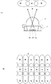
まず、3in1の発光ダイオードの特性について説明する。図9(A)は、3in1の発光ダイオードを並べて配置した時の各色の光出射方向を示す。図9(A)に示すように、3in1の発光ダイオードでは、赤色の発光素子2Rが中心に配置されており、その一方側に緑色の発光素子2Gが配置され、反対側に青色の発光素子2Bが実装されている。これにより、レンズキャップ4を介して発光素子2R,2B,2Gから出射される光には、角度ずれ(光軸ずれ)が発生する。この光軸ずれは、図9(B)に示すように、照射面Fにおける色の偏りを引き起こす。この色の偏りは、植物の育成等に不均一性をもたらず。図10に示す光照射装置ユニット100Bは、このような照射面による光の色の偏りを解消する。
First, characteristics of the 3-in-1 light-emitting diode will be described. FIG. 9A shows the light emission direction of each color when 3 in 1 light emitting diodes are arranged side by side. As shown in FIG. 9A, in the 3in1 light emitting diode, the red
図10に示すように、本実施の形態に係る光照射装置ユニット100Bは、基板1Bを中心に構成されている。基板1B上の一方面(+Z側の面)には、複数の発光ダイオード2,3が配列されている。複数の発光ダイオード2は、基板1BのY軸方向に延びる外辺に平行な方向に等間隔に2列配列されている。また、複数の発光ダイオード3は、基板1BのY軸方向に延びる外辺に平行な方向に等間隔に1列配列されている。
As shown in FIG. 10, the light
支線5は、複数の発光ダイオード2のうち、Y軸方向に一列に並ぶ発光ダイオード2をそれぞれ直列に接続する。支線5は、発光ダイオード2の発光素子2R,2G,2B、定電流ダイオード(CCR)13とそれぞれ接続するために一列につき3本設けられている。
The
支線6は、複数の発光ダイオード3のうち、Y軸方向に一列に並ぶ発光ダイオード3、定電流ダイオード(CCR)13をそれぞれ直列に接続する。
The
第1の幹線7、第2の幹線8は、3本の支線5と1本の支線6それぞれに対応してそれぞれ計4本設けられている。第1の幹線7は、Y軸方向に延びており、複数の支線5,6それぞれの一方端(+Y端)と電気接続している。第2の幹線8は、Y軸方向に延びており、複数の支線5,6それぞれの他方端(−Y端)と電気接続している。
A total of four
光照射装置ユニット100Bでは、各発光ダイオード2に実装された複数の発光素子2R,2G,2BがY方向に並ぶように、複数の発光ダイオード2各々が基板1Bに配設されている。複数の発光ダイオード2は、Y軸方向に並んでいる。これにより、図11に示すように、Y軸方向については、隣接する発光ダイオード2同士の光が補いあって、色の偏りが軽減される。
In the
また、本実施の形態では、発光ダイオード2がX軸方向に2列並んでいる。本実施の形態では、図11(A)に示すように、Y軸方向に並ぶ発光ダイオード2の各列について、発光ダイオード2の赤、緑、青の発光素子2R,2G,2Bの並び順が逆になっている。すなわち、Y軸方向に直交する方向に隣接する発光ダイオード2の向きが互いに逆向きとなるように複数の発光ダイオード2が配置されている。
In the present embodiment, the
このようにすれば、図11(A)に示すように、Y軸方向に隣接する発光ダイオード2の間で、同じ色の光の出射方向の傾斜方向が逆向きとなるので、それらの間で出射方向の傾斜を相殺することができる。この結果、照射面における光の色の偏りをさらに低減することができる。
In this way, as shown in FIG. 11 (A), the
このような配置を実現するために、本実施の形態では、基板1B上の支線5の配線パターンは、矩形波状に折れ曲がっている。
In order to realize such an arrangement, in the present embodiment, the wiring pattern of the
3本の支線5と1本の支線6にはそれぞれ、定電流ダイオード(CCR)13が挿入されている。このようにすれば、同じ支線5,6に接続された複数の発光ダイオード2,3を同一電圧で動作させることができる。
A constant current diode (CCR) 13 is inserted in each of the three
本実施の形態に係る光照射装置ユニット100Bも、図12に示すように、Y軸方向に連結することにより、所望の長さの光照射装置を構成することができる。また、図13(A)及び図13(B)に示すように、X軸方向や、X軸方向及びY軸方向に光照射装置ユニット100Bを連結して所望の大きさの光照射装置を構成し、面光源を構成することができる。
As shown in FIG. 12, the light
本実施の形態でも、発光ダイオ−ド2,3に、レンズキャップ4が搭載されている。レンズキャップ4は、発光ダイオード2,3から出射される光の指向角を調整可能な凸レンズとしての役割を果たす。指向角の調整により、発光ダイオード2,3から出射される光量を調整することができる。
Also in the present embodiment, the
この場合、+Y端、−Y端に実装されている発光ダイオード2,3に搭載するレンズキャップ4の指向角を狭くすることにより、Y軸方向に関して、照射面(植物の育成面)における光量をより強く、かつ、より均一化することができる。このようにすれば、Y軸方向中央の植物に対して、Y軸方向両端の植物の育成が遅れるのを回避することができる。
In this case, by narrowing the directivity angle of the
上記各実施形態では、複数の発光ダイオード2,3を、複数列配列したが、発光ダイオード2,3の配列は一列であってもよい。この場合でも、両端側の発光ダイオード2,3に搭載される狭い指向角を持ったレンズキャップ4(4A)を内側の発光ダイオード2,3に搭載される広い指向角を持ったレンズキャップ4(4C)を配置する事によって照射面の光量を均一化することができる。
In each of the above embodiments, the plurality of
図14(A),図14(B)には、レンズキャップ4を搭載していない場合の照射面における光量分布が示され、図15(A),図15(B)には、レンズキャップ4を搭載した場合の照射面における光量分布が示されている。図14(A)及び図14(B)と、図15(A)及び図15(B)とを比較すると、レンズキャップ4を付けることにより、照射面の光量が大きくなり、かつ、長手方向に均一になっているのがわかる。
14A and 14B show the light amount distribution on the irradiation surface when the
以上述べたように、上記各実施の形態によれば、各発光ダイオード2,3は、出射する光を集光するレンズキャップ4を搭載可能であるため、発光ダイオード2,3から出射される光の光量を調整可能となる。以上の構成を有する光照射装置ユニット100A,100A’,100Bを用いて光照射装置を構成すれば、光源サイズ・光質・光量を、求められる光量に調整可能な光照射装置を得ることができる。
As described above, according to each of the above embodiments, each of the
本発明は、上記各実施の形態に係るものには限られない。光照射装置ユニット100A,100A’,100Bにおける発光ダイオードの配列の数は、適宜変更することが可能である。また、発光ダイオードは3in1ダイオードでなくてもよい。また、レンズキャップ4の種類は、3つには限れず、2つであってもよいし、4つ以上であってもよい。
The present invention is not limited to those according to the above embodiments. The number of light emitting diode arrays in the
この発明は、この発明の広義の精神と範囲を逸脱することなく、様々な実施の形態及び変形が可能とされるものである。また、上述した実施の形態は、この発明を説明するためのものであり、この発明の範囲を限定するものではない。すなわち、この発明の範囲は、実施の形態ではなく、特許請求の範囲によって示される。そして、特許請求の範囲内及びそれと同等の発明の意義の範囲内で施される様々な変形が、この発明の範囲内とみなされる。 Various embodiments and modifications can be made to the present invention without departing from the broad spirit and scope of the present invention. The above-described embodiments are for explaining the present invention and do not limit the scope of the present invention. In other words, the scope of the present invention is shown not by the embodiments but by the claims. Various modifications within the scope of the claims and within the scope of the equivalent invention are considered to be within the scope of the present invention.
本発明は、例えば、植物工場における植物の育成用の光照射装置に適用することができる。この光照射装置は、例えば植物・藻類等の育成用・補光用・電照用光照射、化学物質分解用光照射、集魚灯、殺菌用光照射等に用いられる。 The present invention can be applied to, for example, a light irradiation apparatus for growing plants in a plant factory. This light irradiation device is used, for example, for irradiating plants, algae, etc., for irradiating light, for supplementing light, for illuminating light, for irradiating chemical substances, for collecting fish, for sterilizing light, etc.
1A,1B 基板
2 発光ダイオード(3in1)
2’ 発光ダイオード(1in1)
2A,2R,2B,2G 発光素子
2R1,2R2 電極
3 発光ダイオード(1in1)
4(4A,4B,4C) レンズキャップ
5,6 支線
7 第1の幹線
8 第2の幹線
9 第1の外部端子
10 第2の外部端子
11 放熱板
12 ジャンパー線
13 定電流ダイオード(CCR)
100A,100A’,100B 光照射装置ユニット
F 照射面
1A,
2 'light emitting diode (1in1)
2A, 2R, 2B, 2G Light emitting element 2R1,
4 (4A, 4B, 4C)
100A, 100A ′, 100B Light irradiation unit F irradiation surface
Claims (5)
前記基板の一方面上で、前記基板の外辺に平行な第1の方向に等間隔に配列され、出力する光の指向角を調整可能な凸レンズ状のレンズキャップをそれぞれ搭載可能な複数の表面実装型の発光ダイオードと、
前記発光ダイオードのうち、前記第1の方向に並ぶ発光ダイオードを直列に接続する支線と、
前記支線の一方端と電気接続し、前記基板の外辺に平行な第2の方向に延びる第1の幹線と、
前記支線の他方端と電気接続し、前記第2の方向に延びる第2の幹線と、
前記第1の幹線と外部の電気回路とを電気接続するために前記第1の幹線の両端に設けられた第1の外部端子と、
前記第2の幹線と外部の電気回路とを電気接続するために前記第2の幹線の両端に設けられた第2の外部端子と、
を備え、
前記発光ダイオードには、複数の異なる光質の光を発光する発光素子が実装されており、
前記支線、前記第1の幹線、前記第2の幹線、前記第1の外部端子及び前記第2の外部端子が、前記発光素子の光質毎に設けられ、
前記発光ダイオードに内蔵された複数の発光素子が前記第1の方向に並ぶように、前記発光ダイオード各々が前記基板に配設されており、
前記発光ダイオードは、前記第1の方向に複数列配列され、
前記第1の方向に直交する方向に隣接する発光ダイオードの向きが互いに逆向きとなるように前記発光ダイオードが配置されている、光照射装置ユニット。 A rectangular substrate;
A plurality of surfaces on which a convex lens-shaped lens cap can be mounted on one surface of the substrate, arranged at equal intervals in a first direction parallel to the outer side of the substrate, and capable of adjusting the directivity angle of the output light. Mountable light emitting diode,
Of the light emitting diodes, branch lines connecting the light emitting diodes arranged in the first direction in series;
A first trunk line electrically connected to one end of the branch line and extending in a second direction parallel to the outer edge of the substrate;
A second trunk line electrically connected to the other end of the branch line and extending in the second direction;
First external terminals provided at both ends of the first main line for electrically connecting the first main line and an external electric circuit;
Second external terminals provided at both ends of the second main line for electrically connecting the second main line and an external electric circuit;
Equipped with a,
The light emitting diode is mounted with a light emitting element that emits light of a plurality of different light qualities,
The branch line, the first trunk line, the second trunk line, the first external terminal and the second external terminal are provided for each light quality of the light emitting element,
Each of the light emitting diodes is disposed on the substrate such that a plurality of light emitting elements incorporated in the light emitting diode are arranged in the first direction,
The light emitting diodes are arranged in a plurality of rows in the first direction,
The light irradiation device unit , wherein the light emitting diodes are arranged such that directions of light emitting diodes adjacent to each other in a direction orthogonal to the first direction are opposite to each other .
請求項1に記載の光照射装置ユニット。 In the branch line, a constant current diode or an electric resistance for keeping a flowing current constant is inserted,
The light irradiation apparatus unit according to claim 1 .
前記第1の幹線及び前記第2の幹線は、スルーホールを介して、前記支線と電気接続されている、
請求項1又は2に記載の光照射装置ユニット。 The first trunk line and the second trunk line are provided on the other surface of the substrate,
The first trunk line and the second trunk line are electrically connected to the branch line through a through hole.
Light irradiation apparatus unit according to claim 1 or 2.
前記発光ダイオードが設けられた発光領域の裏側の領域に放熱板が設けられている、
請求項1から3のいずれか一項に記載の光照射装置ユニット。 On the other side of the substrate,
A heat sink is provided in a region on the back side of the light emitting region provided with the light emitting diode,
The light irradiation apparatus unit as described in any one of Claim 1 to 3 .
請求項1から4のいずれか一項に記載の光照射装置ユニット。 When the light emitting diode is the substrate has been laid so as to face the same side, towards the end from the center of the array of light emitting diodes, as the directivity angle of the output Shako becomes narrow, and with respect to the light emitting diode lenses cap is attached,
The light irradiation apparatus unit as described in any one of Claim 1 to 4 .
Priority Applications (1)
| Application Number | Priority Date | Filing Date | Title |
|---|---|---|---|
| JP2016019263A JP6075813B1 (en) | 2016-02-03 | 2016-02-03 | Light irradiation unit |
Applications Claiming Priority (1)
| Application Number | Priority Date | Filing Date | Title |
|---|---|---|---|
| JP2016019263A JP6075813B1 (en) | 2016-02-03 | 2016-02-03 | Light irradiation unit |
Publications (2)
| Publication Number | Publication Date |
|---|---|
| JP6075813B1 true JP6075813B1 (en) | 2017-02-08 |
| JP2017136018A JP2017136018A (en) | 2017-08-10 |
Family
ID=57981578
Family Applications (1)
| Application Number | Title | Priority Date | Filing Date |
|---|---|---|---|
| JP2016019263A Expired - Fee Related JP6075813B1 (en) | 2016-02-03 | 2016-02-03 | Light irradiation unit |
Country Status (1)
| Country | Link |
|---|---|
| JP (1) | JP6075813B1 (en) |
Citations (4)
| Publication number | Priority date | Publication date | Assignee | Title |
|---|---|---|---|---|
| JP2007129062A (en) * | 2005-11-04 | 2007-05-24 | Koa Corp | LED light source device |
| JP2012119312A (en) * | 2011-11-09 | 2012-06-21 | Sharp Corp | Plane-emission lighting system |
| JP2014183309A (en) * | 2013-03-15 | 2014-09-29 | Lextar Electronics Corp | Luminous element, direct type backlight module, edge-lit backlight module, plate-shaped lamp and strip-shaped luminous element |
| JP2015167512A (en) * | 2014-03-07 | 2015-09-28 | 株式会社環境フォトニクス | Light irradiation device |
-
2016
- 2016-02-03 JP JP2016019263A patent/JP6075813B1/en not_active Expired - Fee Related
Patent Citations (4)
| Publication number | Priority date | Publication date | Assignee | Title |
|---|---|---|---|---|
| JP2007129062A (en) * | 2005-11-04 | 2007-05-24 | Koa Corp | LED light source device |
| JP2012119312A (en) * | 2011-11-09 | 2012-06-21 | Sharp Corp | Plane-emission lighting system |
| JP2014183309A (en) * | 2013-03-15 | 2014-09-29 | Lextar Electronics Corp | Luminous element, direct type backlight module, edge-lit backlight module, plate-shaped lamp and strip-shaped luminous element |
| JP2015167512A (en) * | 2014-03-07 | 2015-09-28 | 株式会社環境フォトニクス | Light irradiation device |
Also Published As
| Publication number | Publication date |
|---|---|
| JP2017136018A (en) | 2017-08-10 |
Similar Documents
| Publication | Publication Date | Title |
|---|---|---|
| US7963664B2 (en) | Lighting device with OLEDs | |
| US7878681B2 (en) | Illumination device | |
| JP6868731B2 (en) | LED device with LED modules that can be individually specified | |
| KR101290136B1 (en) | Illumination device | |
| US10764981B2 (en) | Tunable LED light array for horticulture | |
| US10837619B2 (en) | Optical system for multi-emitter LED-based lighting devices | |
| GB2464102A (en) | Illumination apparatus comprising multiple monolithic subarrays | |
| US10400994B2 (en) | LED illumination module with fixed optic and variable emission pattern | |
| CN105122450A (en) | Optical arrangement and display device | |
| KR20090018867A (en) | Lighting equipment | |
| GB2417824A (en) | LED light source | |
| JP5575132B2 (en) | Headlamp with multiple light emitting diode radiators | |
| JP6675151B2 (en) | Light irradiation device | |
| ES2878045T3 (en) | Multicolor lights matrix | |
| JP7618892B2 (en) | Lighting Device | |
| JP6075813B1 (en) | Light irradiation unit | |
| US20130201669A1 (en) | Led illumination apparatus with improved output uniformity | |
| JP7362681B2 (en) | Plant cultivation facilities, plant cultivation methods, LED lighting devices for plant cultivation, shelves for plant cultivation shelves, and plant cultivation shelves | |
| KR20180110614A (en) | Light emitting device and light illuminating apparatus comprising the light emitting device | |
| US12211885B2 (en) | Semiconductor light emitting device | |
| CN114783314A (en) | LED light-emitting module | |
| KR102464568B1 (en) | ordered array of LEDs | |
| KR20170010456A (en) | Backlight module with mjt led and backlight unit having the same | |
| US20070215891A1 (en) | Collimated LED array with reflector | |
| KR101304611B1 (en) | Light emitting diode package and light emitting diode array using the same |
Legal Events
| Date | Code | Title | Description |
|---|---|---|---|
| TRDD | Decision of grant or rejection written | ||
| A01 | Written decision to grant a patent or to grant a registration (utility model) |
Free format text: JAPANESE INTERMEDIATE CODE: A01 Effective date: 20161220 |
|
| A61 | First payment of annual fees (during grant procedure) |
Free format text: JAPANESE INTERMEDIATE CODE: A61 Effective date: 20170105 |
|
| R150 | Certificate of patent or registration of utility model |
Ref document number: 6075813 Country of ref document: JP Free format text: JAPANESE INTERMEDIATE CODE: R150 |
|
| R250 | Receipt of annual fees |
Free format text: JAPANESE INTERMEDIATE CODE: R250 |
|
| LAPS | Cancellation because of no payment of annual fees |