JP6074503B2 - Holder and medical instrument - Google Patents
Holder and medical instrument Download PDFInfo
- Publication number
- JP6074503B2 JP6074503B2 JP2015523455A JP2015523455A JP6074503B2 JP 6074503 B2 JP6074503 B2 JP 6074503B2 JP 2015523455 A JP2015523455 A JP 2015523455A JP 2015523455 A JP2015523455 A JP 2015523455A JP 6074503 B2 JP6074503 B2 JP 6074503B2
- Authority
- JP
- Japan
- Prior art keywords
- holder
- coupling element
- coupling
- instrument
- axial opening
- Prior art date
- Legal status (The legal status is an assumption and is not a legal conclusion. Google has not performed a legal analysis and makes no representation as to the accuracy of the status listed.)
- Expired - Fee Related
Links
- 230000008878 coupling Effects 0.000 claims description 120
- 238000010168 coupling process Methods 0.000 claims description 120
- 238000005859 coupling reaction Methods 0.000 claims description 120
- 230000000903 blocking effect Effects 0.000 claims description 5
- 230000007423 decrease Effects 0.000 claims description 2
- 238000004140 cleaning Methods 0.000 description 10
- 230000001954 sterilising effect Effects 0.000 description 8
- 238000004659 sterilization and disinfection Methods 0.000 description 8
- 210000003811 finger Anatomy 0.000 description 4
- 239000007943 implant Substances 0.000 description 4
- 210000000988 bone and bone Anatomy 0.000 description 3
- 239000000463 material Substances 0.000 description 3
- 238000000034 method Methods 0.000 description 3
- 238000001356 surgical procedure Methods 0.000 description 3
- 238000010276 construction Methods 0.000 description 2
- 230000001419 dependent effect Effects 0.000 description 2
- 238000005553 drilling Methods 0.000 description 2
- 229910052751 metal Inorganic materials 0.000 description 2
- 239000002184 metal Substances 0.000 description 2
- 210000003813 thumb Anatomy 0.000 description 2
- 206010036790 Productive cough Diseases 0.000 description 1
- 229910001069 Ti alloy Inorganic materials 0.000 description 1
- RTAQQCXQSZGOHL-UHFFFAOYSA-N Titanium Chemical compound [Ti] RTAQQCXQSZGOHL-UHFFFAOYSA-N 0.000 description 1
- 230000005540 biological transmission Effects 0.000 description 1
- 230000015572 biosynthetic process Effects 0.000 description 1
- 239000008280 blood Substances 0.000 description 1
- 210000004369 blood Anatomy 0.000 description 1
- 210000001124 body fluid Anatomy 0.000 description 1
- 239000010839 body fluid Substances 0.000 description 1
- 230000006931 brain damage Effects 0.000 description 1
- 231100000874 brain damage Toxicity 0.000 description 1
- 208000029028 brain injury Diseases 0.000 description 1
- 210000000078 claw Anatomy 0.000 description 1
- 238000011109 contamination Methods 0.000 description 1
- 230000006378 damage Effects 0.000 description 1
- 238000013016 damping Methods 0.000 description 1
- 238000010586 diagram Methods 0.000 description 1
- 230000000694 effects Effects 0.000 description 1
- 238000002513 implantation Methods 0.000 description 1
- 238000007373 indentation Methods 0.000 description 1
- 238000003780 insertion Methods 0.000 description 1
- 230000037431 insertion Effects 0.000 description 1
- 238000004519 manufacturing process Methods 0.000 description 1
- 150000002739 metals Chemical class 0.000 description 1
- 238000003801 milling Methods 0.000 description 1
- 230000007935 neutral effect Effects 0.000 description 1
- 230000000149 penetrating effect Effects 0.000 description 1
- 230000002093 peripheral effect Effects 0.000 description 1
- 230000001105 regulatory effect Effects 0.000 description 1
- 210000004872 soft tissue Anatomy 0.000 description 1
- 210000003802 sputum Anatomy 0.000 description 1
- 208000024794 sputum Diseases 0.000 description 1
- 239000010935 stainless steel Substances 0.000 description 1
- 229910001220 stainless steel Inorganic materials 0.000 description 1
- 210000001519 tissue Anatomy 0.000 description 1
- 239000010936 titanium Substances 0.000 description 1
- 229910052719 titanium Inorganic materials 0.000 description 1
Images


Classifications
-
- A—HUMAN NECESSITIES
- A61—MEDICAL OR VETERINARY SCIENCE; HYGIENE
- A61B—DIAGNOSIS; SURGERY; IDENTIFICATION
- A61B17/00—Surgical instruments, devices or methods, e.g. tourniquets
- A61B17/16—Bone cutting, breaking or removal means other than saws, e.g. Osteoclasts; Drills or chisels for bones; Trepans
- A61B17/1613—Component parts
- A61B17/162—Chucks or tool parts which are to be held in a chuck
-
- A—HUMAN NECESSITIES
- A61—MEDICAL OR VETERINARY SCIENCE; HYGIENE
- A61B—DIAGNOSIS; SURGERY; IDENTIFICATION
- A61B17/00—Surgical instruments, devices or methods, e.g. tourniquets
- A61B2017/0046—Surgical instruments, devices or methods, e.g. tourniquets with a releasable handle; with handle and operating part separable
-
- A—HUMAN NECESSITIES
- A61—MEDICAL OR VETERINARY SCIENCE; HYGIENE
- A61B—DIAGNOSIS; SURGERY; IDENTIFICATION
- A61B17/00—Surgical instruments, devices or methods, e.g. tourniquets
- A61B2017/00477—Coupling
-
- A—HUMAN NECESSITIES
- A61—MEDICAL OR VETERINARY SCIENCE; HYGIENE
- A61B—DIAGNOSIS; SURGERY; IDENTIFICATION
- A61B17/00—Surgical instruments, devices or methods, e.g. tourniquets
- A61B2017/00831—Material properties
- A61B2017/00862—Material properties elastic or resilient
Landscapes
- Health & Medical Sciences (AREA)
- Surgery (AREA)
- Life Sciences & Earth Sciences (AREA)
- Biomedical Technology (AREA)
- Medical Informatics (AREA)
- Orthopedic Medicine & Surgery (AREA)
- Oral & Maxillofacial Surgery (AREA)
- Engineering & Computer Science (AREA)
- Dentistry (AREA)
- Heart & Thoracic Surgery (AREA)
- Nuclear Medicine, Radiotherapy & Molecular Imaging (AREA)
- Molecular Biology (AREA)
- Animal Behavior & Ethology (AREA)
- General Health & Medical Sciences (AREA)
- Public Health (AREA)
- Veterinary Medicine (AREA)
- Dental Tools And Instruments Or Auxiliary Dental Instruments (AREA)
- Surgical Instruments (AREA)
Description
本発明は、逃げ溝を有する医療用器具の器具シャフトの接続端部を収容するためのクイックカップリングを備えたホルダ、および、そのホルダに接続可能な医療用器具に関する。 The present invention includes a holder having a quick coupling for accommodating the connecting end of the instrument shaft of a medical instrument having a relief groove, and relates with great care medical devices that can be connected to the holder.
この種のホルダは、少なくとも、装入および使用のために同軸上に保持される医療用器具の固定の際に利用される。同軸上の固定は、ホルダと器具との間の軸方向の遊びを可能にするが、器具を、ホルダから軸方向に例えば非意図的に弛ませることなく、確実にホルダに固定するものである。また多くの場合、モータ駆動により生み出された力や手動で生み出された力が、軸方向だけでなく、医療用器具の回転駆動のためにも伝動されなければならない。このような場合、対応するホルダには、医療用器具の捩じり応力に強い収容のための手段と、ホルダと医療用器具との結合のための手段を追加的に設ける必要がある。 This type of holder is used at least for securing medical devices that are held coaxially for loading and use. Coaxial fixation allows for axial play between the holder and the instrument, but ensures that the instrument is secured to the holder in the axial direction, for example without unintentional loosening. . Also, in many cases, the force generated by the motor drive or manually generated force must be transmitted not only in the axial direction but also for the rotational drive of the medical instrument. In such a case, it is necessary to additionally provide the corresponding holder with a means for accommodating the medical device against torsional stress and a means for coupling the holder and the medical device.
この説明および発明の意味する医療用器具とは、特に、穿孔器、フライス盤、やすり、突き錐、のこぎり、およびこれらに類する医療に使用されるツールのことである。しかし、本発明における医療用器具は、特に内部人工器官も含む人工器官の一部としてのインプラント、および、その他のハンドリングのためのホルダを含み、装着、除去、移植およびその他の医療ステップにおいて結合されるべきインプラントに関して、インプラントの一部およびインプラント自体も、外科用器具と解釈できる。 Medical instruments within the meaning of this description and invention are in particular perforators, milling machines, files, awls, saws, and similar medical tools. However, the medical device according to the present invention includes an implant as part of a prosthesis, particularly including an endoprosthesis, and a holder for other handling, and is combined in mounting, removal, implantation and other medical steps. With respect to the implant to be, part of the implant and the implant itself can also be interpreted as a surgical instrument.
この種のホルダは、例えば独国特許出願公開第602004001063号公報の構成が知られている。この文献では、図1に医療用器具として、その器具シャフトの接続端部に、符号78が付けられた、ハドソン(Hudson)・コネクタまたはトリンクル(Trinkle)・アダプタと呼ばれる接続形態の拡孔錐が示されている。この拡孔錐は、固定するためにホルダのクイックカップリングに導入される。このホルダは、締付けスリーブの捩り込みによって器具シャフトの接続端部の逃げ溝に係合するチャック爪を有する締付けチャックのように固定される。この文献の図4には、他の設計例が示されているが、この設計例では、器具シャフトの接続端部のロックはロッキングボールを用いて行われる。 This type of holder is known, for example, in the configuration of German Patent Application Publication No. 602004001063. In this document, as a medical instrument in FIG. 1, there is an expanded cone of a connection form called a Hudson connector or a Trickle adapter, which has a reference numeral 78 attached to the connection end of the instrument shaft. It is shown. This expanded cone is introduced into the quick coupling of the holder for fixing. This holder is fixed like a clamping chuck having a chuck claw that engages with a relief groove at the connecting end of the instrument shaft by twisting of the clamping sleeve. FIG. 4 of this document shows another design example. In this design example, locking of the connecting end portion of the instrument shaft is performed using a locking ball.
シャフト形のホルダを他の方法で外科用器具に結合するその他の技術は、欧州特許出願公開第0893097号公報および独国特許第2009469号明細書に示されている。 Other techniques for coupling the surgical instrument shaft-shaped holder in another way is shown in European Patent Application Publication No. 0893097 Publication and German Patent 2,009,469.
特に、この種のホルダのように、通常、医療用器具が接続されたホルダが手術および処置の進行中に使用される場合には、定期的に医療用器具自体だけではなく、ホルダも、例えば血液その他の体液、手術中に溶解した組織成分、骨細片、および、骨破片や、それに類したものによって、特にクイックカップリングの部分が汚染される。こうしたホルダは、通常は一回限りで使用するものではなく繰り返し利用可能な器具であるため、使用後で再度利用する前に、適切に洗浄されかつ殺菌されなければならない。そして、通常、ホルダの従来のクイックカップリングに備えられた小部品、特にこの種の部品間における僅かな寸法の隙間や空間は、残滓の無い洗浄および完全な殺菌に際して、特に障害となる。すなわちホルダにおけるこの種のクイックカップリングが分解可能な場合には、洗浄および殺菌を行う者が、これらのクイックカップリングを分解するだけでなく、小部品も洗浄および殺菌のために念入りに取り扱われ、接続する際には、クイックカップリングを再び適切に組み立てなければならない。一方、クイックカップリングが分解可能でない場合には、例えばロッキングボールの座の部分に生じるような小さな隙間や中間スペースに残滓が無いように洗浄しかつ殺菌することは、ほとんど不可能である。そのため、ホルダの再度の使用に際し、その後の医療処置の途中で合併症に繋がる可能性があり、汚染残滓の危険性が考えられる。 In particular, when a holder to which a medical instrument is connected, such as a holder of this kind, is used during the course of surgery and treatment, not only the medical instrument itself but also the holder, for example, Blood and other body fluids, tissue components dissolved during surgery, bone debris, bone debris, and the like can contaminate especially the quick coupling area. Since these holders are usually reusable instruments rather than used once, they must be properly cleaned and sterilized before being reused after use. In general, the small parts provided in the conventional quick coupling of the holder, in particular small gaps or spaces between such parts, are particularly impediments for cleaning without residue and for complete sterilization. That is, if this type of quick coupling in the holder can be disassembled, the person performing the cleaning and sterilization not only disassembles these quick couplings, but also small parts are carefully handled for cleaning and sterilization. When connecting, the quick coupling must be reassembled properly. On the other hand, if the quick coupling cannot be disassembled, for example, it is almost impossible to clean and sterilize so that there is no residue in a small gap or an intermediate space that occurs in the seat portion of the rocking ball. Therefore, when the holder is used again, there is a possibility that it may lead to complications during the subsequent medical treatment, and there is a risk of contamination residue.
したがって、本発明の課題は、周知の同種の医療用器具、特に外科用器具のためのホルダを、従来のホルダに対して構造を簡略化でき、かつ、使用後のアフターケアにおいて簡単に洗浄および殺菌できるという趣旨に沿うものである。 The object of the present invention is therefore to simplify the structure of known similar medical devices, in particular surgical tools, relative to conventional holders, and to be easily cleaned and used in aftercare after use. This is in line with the idea that it can be sterilized.
この課題は、請求項1の特徴を有する医療用器具、特に外科用器具のためのホルダによって解決される。このようなホルダの有利な構成は、従属項である請求項2ないし8に示されている。さらに、本発明における課題解決のその他の観点は、請求項1ないし8いずれか一に記載のホルダと、このホルダに着脱自在な器具シャフトとを備えた医療用器具に関する請求項9や、この請求項9に従属する請求項10ないし12の構成である。
This object is solved by a holder for a medical instrument, in particular a surgical instrument, having the features of
すなわち本発明に係る医療用器具、特に外科用器具のための新型のホルダは、医療用器具の器具シャフトにおける逃げ溝を有する接続端部を接続して収容するためのクイックカップリングを有している。このクイックカップリングは、接続端部を収容可能な第1の軸方向開口部を有する第1のカップリングエレメントを備えている。また、クイックカップリングは、接続端部に対応した第2の軸方向開口部を有する第2のカップリングエレメントを備えている。第1のカップリングエレメントおよび第2のカップリングエレメントは、第2の開口部の縁が器具シャフトの接続端部において逃げ溝に係合してロックするように第1の開口部と第2の開口部とが軸方向に相対的に変位するロック位置から解除位置へ移行するために、開口部の軸方向に対して斜め方向に互いに相対的に移動可能である。また、解除位置では、第1の軸方向開口部と第2の軸方向開口部とが、少なくとも接続端部が第1の軸方向開口部および第2の軸方向開口部から抜き差し自在となる程度に直線上に離間して配置される。さらに、第1のカップリングエレメントおよび第2のカップリングエレメントは、スプリングユニットを介して互いに一体に接続されており、このスプリングユニットは、第1のカップリングエレメントおよび第2のカップリングエレメントをロック位置に向かって互いに相対的に付勢する。 That is, a new type of holder for a medical instrument, particularly a surgical instrument according to the present invention has a quick coupling for connecting and accommodating a connecting end portion having a relief groove in the instrument shaft of the medical instrument. Yes. The quick coupling includes a first coupling element having a first axial opening that can accommodate a connection end. The quick coupling also includes a second coupling element having a second axial opening corresponding to the connection end. First coupling elements and second coupling elements of the second opening edge at the connection end of the instrument shaft engages in the relief groove first to lock in the opening and the second to the opening moves to the release position from the lock position relatively displaced in the axial direction and can move relative to each other in an oblique direction with respect to the axial direction of the opening. Further, in the release position, the extent to which a first axial opening and a second axial opening, at least the connection end portion becomes telescopically from a first axial opening and a second axial opening Are spaced apart on a straight line. In addition, the first coupling element and the second coupling element of the via spring unit are integrally connected to each other, this spring unit has a first coupling element and the second coupling element of the Biasing each other toward the lock position.
この種の構造のホルダでは、クイックカップリングに、例えばロッキングボールのようなロッキングエレメントを予め備える必要性がない。すなわち、ホルダでは、第1の軸方向開口部と第2の軸方向開口部とが通常位置として軸方向の延長線に対し互いに斜め方向にずれたロック位置に付勢されることにより、第1のカップリングエレメントの第1の軸方向開口部と第2のカップリングエレメントの第2の軸方向開口部とがオフセット状態となって、ロック作用を奏する。言い換えると、器具シャフトの接続端部と共に第1の開口部を通じて導かれた医療用器具は、まず、この第1の軸方向開口部を通じて半径方向に固定される。また、軸方向の固定またはロックは、接続端部が第2の開口部も貫通することによって行われる。この場合、第2の開口部は、その内周縁で接続端部の逃げ溝に接触して係合するとともに、器具シャフトを軸方向にロックするように、軸方向に対し斜めにスライドする。上述のロック位置においては、さらに軸方向の遊びが存在する。多くの場合、このような軸方向の遊びは、手動ホルダにおいて、追加的な触覚上の補助作用が得られるため、利用者からも望まれていたことである。その他の場合、例えば頭蓋冠部分の硬い骨を穿孔するための器具では、こうした軸方向の遊隙が必要である。すなわち、器具シャフトの後方に向かって軸方向にスライドした位置においてのみ、ばね荷重に抗して器具を押し付けた場合に、穿孔されるべき頭蓋冠へ駆動装置に誘導された回転が作用するためである。しかしこのスライドされた位置は、頭蓋冠が穿孔されると緩んでばねが回転駆動を止めてドリル装置がニュートラルになる。その結果、ドリル駆動がそのまま継続してしまって頭蓋冠の下にある軟組織部分の損傷または脳の損傷が生じることが防止される。 In a holder of this type of structure, there is no need to previously provide a locking element such as a locking ball in the quick coupling. That is, in the holder, the first axial opening and the second axial opening are urged to a locked position that is offset from each other in an oblique direction with respect to the axial extension line as a normal position. It is first axial opening of the coupling element and the second axial opening of the second coupling element is an offset state, exerts a locking action. In other words, the medical instrument guided through the first opening together with the connecting end of the instrument shaft is first fixed radially through this first axial opening. In addition, the axial fixing or locking is performed when the connecting end portion also penetrates the second opening. In this case , the second opening comes into contact with and engages with the escape groove of the connection end at the inner peripheral edge thereof, and slides obliquely with respect to the axial direction so as to lock the instrument shaft in the axial direction. In lock position described above, there are further axial play. In many cases, this axial play is also desired by the user because of the additional tactile aids in the manual holder. In other cases, such axial play is required, for example, in instruments for drilling hard bone in the calvaria. That is, only when the instrument is slid axially toward the rear of the instrument shaft, when the instrument is pressed against the spring load, the rotation induced by the drive device acts on the calvaria to be drilled. is there. However, this slid position is loosened when the calvaria is drilled, and the spring stops rotating and the drilling device becomes neutral. As a result, it is possible to prevent the drill driving from being continued and causing damage to the soft tissue part or brain damage under the calvaria.
その他の本発明に係るホルダの利点は、第1のカップリングエレメントと第2のカップリングエレメントとが結合されて一体的に構成されていることである。この構成によって、ホルダの洗浄および殺菌に際して必要な個別部品および小部品への分解が問題とならない。加えて、特に好ましいホルダ、特にクイックカップリングの構造と形成とにより、互いに一体的に接続した部品間に、適切な洗浄器具を使って巧く到達でき、洗浄および殺菌できる適切な中間スペースを確保できる。こうして例えばロッキングボールのボールベアリング面に関して、中間スペースが、完全に洗浄および殺菌し徹底的に洗浄および殺菌するために十分ではなくなってしまう問題、特に中間スペースが極端に狭くなってしまう問題を回避することができる。 The advantage of the holder according to another present invention is that it is constructed integrally coupled with the first coupling element and the second coupling element. With this configuration, disassembly into individual parts and small parts necessary for cleaning and sterilization of the holder does not cause a problem. In addition, the construction and formation of the particularly preferred holders, in particular quick couplings, ensure that there is a suitable intermediate space that can be skillfully reached and properly cleaned and sterilized by means of suitable cleaning tools between the parts connected together. it can. Thus, for example, with respect to the ball bearing surface of a rocking ball, the problem of the intermediate space becoming insufficient for complete cleaning and sterilization and thorough cleaning and sterilization, in particular the problem of extremely narrow intermediate space is avoided. be able to.
クイックカップリングは、全体として一体的に形成することが好ましく、簡単に殺菌可能で、また優先的に手術および処置のために十分な生体適合性を有する材料、特に医療用として使用可能なステンレスのような材料にて形成される。こうした金属の利用(チタンまたはチタン合金のような医療に使用可能なその他の金属も利用可能である)により、比較的薄い材料を用いて、ロック位置の方向に向かって十分な復元力を生み出すスプリングユニットを、第1のカップリングエレメントと第2のカップリングエレメントとの一体的な接続に適用する構成が好適である。 The quick coupling is preferably integrally formed as a whole, is easily sterilized, and is preferentially biocompatible with sufficient biocompatibility for surgery and procedures, especially stainless steel that can be used for medical purposes . It is formed with such a material. With such use of metal (Medical available of other metals such as titanium or titanium alloy are also available), using a relatively thin had materials, a sufficient restoring force in the direction of the locked position A configuration in which the generated spring unit is applied to an integral connection between the first coupling element and the second coupling element is preferable.
本発明に係るホルダは、ホルダ内でクイックカップリングに対して器具が回転して捩れにくく配置するため、器具シャフトの接続端部における反対構造と共に作用する遮断構造を有する構成が好ましい。この種の構成は、特に、ホルダによって回転力または回転モーメントを、例えばドリルまたは拡孔錐といった医療用器具に伝達しなければならない場合に重要である。この種の遮断構造のために考えられる構成は、第1のカップリングエレメントの外側面における第1の軸方向開口部に臨む前部を有するクイックカップリングにおいて、前部の表面を貫く開口部の互いに対向する側に、サイドカバーを配置する構成である。 Holder according to the present invention, since the instrument relative to quick coupling with the holder are arranged not easily twisted by rotation, configuration having a blocking structure which acts together with the opposite configuration at the connection end of the instrument shaft is preferred. This type of configuration is particularly important when the rotational force or moment must be transmitted by means of a holder to a medical instrument, for example a drill or an expanding cone. A possible configuration for this type of blocking structure is a quick coupling having a front facing the first axial opening on the outer surface of the first coupling element, with the opening penetrating through the front surface. In this configuration, side covers are arranged on opposite sides.
このサイドカバーは前部の表面から外側に向かって延びており、遮断構造を構成し、互いに平行で対向した平らな接触面を有する。接触面は、器具シャフトの接続端部に形成された反対構造の反対面に倣った形状であり、接触面と反対構造とは互いに対応している。 The side cover extends outward from the front surface, forms a blocking structure, and has flat contact surfaces that are parallel and opposed to each other. Contact surfaces, Ri shape der that follows on the opposite surface of the opposite structures formed in the connection end of the instrument shaft, that correspond to each other opposite structure and the contact surface.
本発明に係るホルダの優先的な構成において、クイックカップリングは基体を有し、この基体には、第1のカップリングエレメントおよび第2のカップリングエレメントが一体に成形されている。その際、基体にはリセス(窪み)が設けられ、このリセスは、一方側が基体の壁によって制限され、またこのリセスに沿って、前記壁が対向する他方側である基体の外側にスプリングユニットが配置され、そしてスプリングユニットに対し角度をつけて傾斜状に第2のカップリングエレメントが配置されている。この構成は、簡単に製造されるための設計オプションであり、同時にホルダ、特にクイックカップリング部分において簡単に洗浄および殺菌が可能であるという要件を満たすことができる。すなわち、リセスが十分に大きく設けられて、基体の壁とスプリングユニットとの間の中間スペースが洗浄器具の挿入のために十分広く確保されていれば、簡単に洗浄および殺菌できる。またリセスは、同じく角部を有する構成が好ましく、特にその延び(形状)において、スプリングユニットの角部のある形状と、このスプリングユニットの角部に対応する角度で延びる第2のカップリングエレメントの角部の形状とに基づいて構成可能である。 In the preferential configuration of the holder according to the present invention, the quick coupling has a base body on which the first coupling element and the second coupling element are integrally formed. At this time, the base is provided with a recess (indentation), one side of which is limited by the wall of the base, and a spring unit is provided along the recess on the other side of the base opposite to the wall. A second coupling element is arranged and is inclined at an angle to the spring unit. This configuration is a design option for easy manufacture and at the same time can meet the requirement that the holder, in particular the quick coupling part, can be easily cleaned and sterilized. That is, if the recess is provided sufficiently large and an intermediate space between the base wall and the spring unit is sufficiently wide for insertion of the cleaning tool, cleaning and sterilization can be easily performed. The recess is also preferably configured to have a corner portion, especially in its extended (shape), the shape having the corner portions of the spring unit, the second coupling elements Ru extending at an angle corresponding to the corner portion of the spring unit configurable Ru der based on the corner shape of the.
さらに、本発明に係るホルダの有利な設計オプションでは、リセスが雌フランジを有し、第2のカップリングエレメントが雄フランジを有し(当然のことながら、逆の構成、すなわちリセスが雄フランジを有し、カップリングエレメントが雌フランジを有する構成でもよい。)、これら雌フランジと雄フランジとがロック位置で当接することによって、第1のカップリングエレメントに対する第2のカップリングエレメントの相対移動をロック位置で係止して、ロック位置を超えてしまうことを防止するストッパとして作用する構成が好適である。このようなストッパ作用は、誤った操作を防止し、総じて、本発明に係るホルダの安定性と信頼性とを向上できる。 Furthermore, an advantageous design option of the holder according to the invention is that the recess has a female flange and the second coupling element has a male flange (which is of course the opposite configuration, i.e. the recess has a male flange). And the coupling element may have a female flange.) When the female flange and the male flange come into contact with each other in the locked position, the relative movement of the second coupling element with respect to the first coupling element is achieved . engaged in the locked position, it is preferred arrangement which acts as a stop to prevent exceeding the locked position. Such a stopper action prevents an erroneous operation and generally improves the stability and reliability of the holder according to the present invention.
本発明のその他の有利な設計では、スプリングユニットをホルダの外側面に配置でき、このような配置により、ロック位置から解除位置に第2のカップリングエレメントを移動させるため、ホルダの縦軸方向に対し斜めに働く力、具体的にはスプリングユニットの減衰効果により働く力、特に圧縮力を、手動でこのホルダの外側面に作用させることができる。言い換えると、スプリングユニットが「圧力スイッチ」として作用し、これを作動させることにより、第1のカップリングエレメントと第2のカップリングエレメントとの相対位置を、ロック位置から解除位置へ移行でき、解除位置においては、ホルダに接続された器具をホルダから解除可能であり、かつ、器具シャフトの接続端部をホルダのクイックカップリングに導入し固定可能である。 In another advantageous design of the invention, the spring unit can be arranged on the outer surface of the holder, and this arrangement moves the second coupling element from the locked position to the released position, so A force acting obliquely, specifically, a force acting by a damping effect of the spring unit, particularly a compressive force, can be manually applied to the outer surface of the holder. In other words, the spring unit acts as a “pressure switch”, and by operating it , the relative position of the first coupling element and the second coupling element can be shifted from the locked position to the released position, and released. in the position, a releasable the connected instrument holder from the holder, and a introducing connecting end portion of the bowl member shaft quick coupling of holder fixable.
ホルダは、特に回転シャフトを使い手動で作動する構成にしてもよく、この構成では、一方の自由端部にクイックカップリングが配置され、また自由端部とは反対側の他方の端部に、例えばT字型のグリップ部分が配置される。しかし、この種のホルダに限定されておらず、本発明に係るホルダは、その他の形状で手動で操作する設計にしてもよい。例えば軸方向に作動する駆動装置や、回転駆動する駆動装置を、モータで駆動する器具駆動装置の一部としても実現できる。 The holder may in particular be configured to be manually operated using a rotating shaft, in which a quick coupling is arranged at one free end and at the other end opposite the free end, For example, a T-shaped grip portion is arranged. However, not limited to this type of holder, the holder according to the present invention may be manually designed to operate in other shapes. For example the drive device and which work moving axially, a driving unit for driving rotation, can also be realized as part of the instrument driving device for driving a motor.
本発明のその他の構成としては、上述のようなホルダと、ホルダに着脱自在に固定可能な少なくとも一つの医療用器具、特に外科用器具との組み合せも存在する。この医療用器具は、接続端部を有する器具シャフトを備え、また、器具シャフトの接続端部に逃げ溝が形成されている。このような組み合せは、ホルダとただ1つの医療用器具とに限定されるものではなく、ホルダと1つまたは複数の医療用器具との組み合わせにしてもよい。 As another configuration of the present invention, there is a combination of the above-described holder and at least one medical instrument that can be detachably fixed to the holder, particularly a surgical instrument. The medical instrument comprises an instrument shaft having a connecting end portion, also, clearance groove connection end of the instrument shaft is formed. Such a combination is not limited to a holder and just one medical instrument, but may be a combination of a holder and one or more medical instruments.
このような組み合せにおける好ましい設計は、医療用器具がその器具シャフトの接続端部の自由端部より基端側に、器具シャフトの自由端部から円錐形に広がるように厚くなった部分である接続部を有し、この接続部は、基端部が逃げ溝より大径である。すなわち、接続部は、基端部から自由端部へ向かって漸次小径に形成されている。また、接続部が、逃げ溝の終端部分で、自由端部と対向し、かつ、器具シャフトにおけるより小さな範囲で僅かに低く段差状に形成されるという利点を有する。この円錐形の厚くなった部分(接続部)により、クイックカップリングへの器具シャフトの接続端部をより容易に導入できる。接続部によって、軸方向に向けられた圧縮力が器具シャフトに作用する際、クイックカップリングの第2のカップリングエレメントが、ロック位置から押し出され解除位置へ移動するとともに、第2のカップリングエレメントが、接続部より基端側の逃げ溝に達して、ロック位置でパチンと閉まり、接続端部が固定される。 Definitive preferred design for such combinations is proximal to the free end portion of the medical instrument connecting end portion of the instrument shaft, it is thickened portion so as to spread conically from the free end portion of the instrument shaft It has a connecting part , and this connecting part has a base end larger in diameter than the escape groove. That is, the connecting portion is formed so as to gradually decrease in diameter from the base end portion toward the free end portion. In addition, the connecting portion has an advantage that it is formed in a stepped shape at a terminal portion of the escape groove, facing the free end portion, and slightly lower in a smaller range of the instrument shaft. This conical thickened part (connecting part) makes it easier to introduce the connecting end of the instrument shaft to the quick coupling. When the axially applied compressive force is applied to the instrument shaft by the connecting portion , the second coupling element of the quick coupling is pushed out of the locked position and moved to the release position, and the second coupling element but reach the base end of the relief groove from the connection portion, Ri closed or snap in the locking position, the connecting end portion is fixed.
回転力または回転モーメントの伝達にとって、上述の医療用器具が、器具シャフトのその接続端部に、反対構造の反対面を構成する平行な平面を有することは有利な構成である。 For transmission of the rotational force, or torque, medical instrument described above, the connection end of the instrument shaft, it is Ru advantageous configuration der having parallel planes constituting the opposite surface of the opposite structure.
本発明の一実施の形態について、図面を参照しながら説明する。 An embodiment of the present invention will be described with reference to the drawings .
各図面は、完全な設計図とみなすことはできず、むしろ、本発明に係るホルダの設計例の発明上最も重要な特徴や、その他の重要な特徴の図示に限定される。 Each Drawing can not be regarded as a complete design diagram, but rather, the invention or on the most important feature of the design example of the holder according to the present invention is limited to the illustrated and other important features.
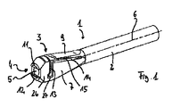
本発明に係る医療用器具、特に外科用器具のためのホルダは、これらの図において様々な(部分)投影図で示され、また全般的に符号1で表示される。 A holder for a medical instrument, in particular a surgical instrument, according to the present invention is shown in these figures in various (partial) projection views and is generally designated 1.
この実施の形態のホルダ1は、シャフト部分2を含め細長く成形されている。このシャフト部分2の一方側の端部である前側端部には、クイックカップリング3が形成されている。このクイックカップリング3は、医療用器具の器具シャフトにおいて、逃げ溝Dを有しホルダ1に結合可能な接続端部Aを収容して接続できる。
The
クイックカップリング3は、第1のカップリングエレメントとしての本体26およびその前部4に、ホルダ1の縦軸6に沿って延びる穴状に形成された第1の軸方向開口部としての受入開口部5を有している。クイックカップリング3は、特に一体的に形成されており、2つの平坦な側面7,8を有し、またこれら側面7,8間に短辺9,10を有している。これら側面7,8および短辺9,10はそれぞれ前部4に向かって開くように楔形に延び、短辺9,10は再び先端に向かって細くなる。短辺9,10は、この先端へ向かって細くなる箇所で前部4において突出した2つの雄フランジ11,12を構成する。
The
第2のカップリングエレメントとしてのカップリングプレート13は、クイックカップリング3を構成する一体的な材料にて形成され、リセスとしてのスロット14を介してクイックカップリング3の本体26から離間したスプリングユニット15と一方側で結合している。スロット14の基端で前部4とは反対側の領域では、スプリングユニット15が、クイックカップリング3の本体26と一体的に接続されている。スプリングユニット15は、短辺9の表面上に位置する平坦面16を有し、この平坦面16は、親指を置くための人間工学的エレメントまたは触覚に関係するエレメントとして構成される。反対側の短辺10には、グリップ凹部17,18,19が設けられている。これらグリップ凹部17,18,19は、使用者の親指が平坦面16で止まるように、手の指、特に人差し指、中指および薬指を配置する。このように手動により、カップリングプレート13の縦スライドを同じ方向に生じさせるために、スプリングユニット15を反対側である短辺10への方向に移動させることができる。カップリングプレート13とスプリングユニット15とは、上述のように、互いに一体的に接続されており、1つの角部を有している。その結果、カップリングプレート13は、基本的に縦軸6に対し垂直に延びるとともに、この縦軸6に沿って延びる受入開口部5の穴と平行方向に延びる。カップリングプレート13は、クイックカップリング3内、正確にはその本体26内のスロット14に対して所定の角度で延びる受入スロット27内に配置されている。受入スロット27内では、カップリングプレート13は受入スロット27に沿って動くことができる。受入スロット27とスロット14とは、互いに所定角度を成してL字型のスロットを形成する。
The
カップリングプレート13には、特に図6に示すように、第2の軸方向開口部としての開口部20が形成されている。この開口部20は、その直線上において同じく軸方向、すなわち延長方向を含め縦軸6に平行に延びているが、スプリングユニット15が開始位置または休止位置にある図6に示す状態では、受入開口部5の中心軸を形成するその中心軸21を含めた縦軸6に対し相対的に移動可能である。受入開口部5は、終端部22に至るまでカップリングプレート13が横断する区域を越えて延びている。また、正面図である図5に示すように、受入開口部5からは、互いに変位した中心軸21および縦軸6と、カップリングプレート13の一部とが認識できる。
As shown in FIG. 6 in particular, the
これに加えて図6に示すように、ホルダ1のシャフト部分2に、めくら穴として設計された受け部23が形成されている。これは、本発明に係るホルダ1をその他の構造、例えば回転駆動装置を備えたモータ器具駆動装置の駆動軸と結合する際、または、例えばホルダ1の縦軸方向に対して斜め、すなわち縦軸6に対し斜め、特に縦軸6に対して垂直に設計されたTグリップと結合する際に利用できる。
In addition, as shown in FIG. 6, a receiving
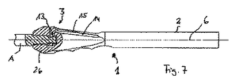
本発明に係るホルダ1のクイックカップリング3は、器具シャフトの接続端部A(図7を参照。)と結合するために構成されている。ここに示された設計および構造では、クイックカップリング3または接続端部Aは、特にいわゆるハドソン(Hudson)・コネクタまたはそれに対応する接続カップリングとして構成されている。
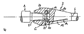
ホルダ1のクイックカップリング3と接続端部Aとの接続方法は、図8(a)ないし図8(c)にそれぞれ示されている。
Method of connecting the
まず、図8(a)に示す開始状態では、ホルダ1のクイックカップリング3が、緩和された開始位置または休止位置にあるスプリングユニット15と共に示されている。この位置では、カップリングプレート13内の受入開口部5と開口部20とは、正確な直線状には調整されていない。それどころか、開口部20を制限するカップリングプレート13の部分24は、受入開口部5の領域内に突出し、その限りでは特に受入開口部5の終端部22の上に重なる。部分24では、この拡大図に示すように、カップリングプレート13は、前部4側に位置する開始傾斜部25を備えている。
First, in the start state shown in FIG. 8A, the
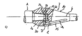
器具シャフトの接続端部Aは、その自由な端部に、直径が先端へ向けて細くなる部分Bとこの部分Bの先端に設けられた接続部Cを有する。また、接続端部Aには、逃げ溝Dが形成される。図8(b)に示すように、接続端部Aが受入開口部5に導入されると、接続部Cがカップリングプレート13の開始傾斜部25に突き当たる。これによって、接続部Cが、上方、すなわち短辺10側へ案内される。スプリングユニット15の弾性と柔軟性とによって、カップリングプレート13はこの短辺10への方向に移動し、その結果、接続部Cが開口部20を通過できる。接続部Cと相互作用する開始傾斜部25の作用は、接続部Cが開口部20を通過可能となる程度に、カップリングプレート13を短辺10の方向にシフトさせるのに十分ではない。そこで、手動により、スプリングユニット15を、スロット14が閉じた状態で反対側である短辺10の方向に押しこむことによって、操作を助長できる。
The connecting end A of the instrument shaft has at its free end a part B whose diameter narrows toward the tip and a connecting part C provided at the tip of this part B. Further, a relief groove D is formed at the connection end A. As shown in FIG. 8B, when the connection end A is introduced into the receiving
接続部Cがカップリングプレート13内の開口部20を完全に通過し、受入開口部5の終端部22に到達すると、カップリングプレート13は、スプリングユニット15のばねの付勢力によって、その休止位置または開始位置であるロック位置に戻りパチンと係合できる。この状態で、接続端部Aの逃げ溝Dの上にある部分24が、接続端部Aの軸方向、すなわちホルダの縦軸6の方向への移動をロックする。接続端部Aをこのロック状態から解除するには、スプリングユニット15を反対側である短辺10の方向に押し込むことによって、受入開口部5と開口部20とが一直線状に配置されて、接続部Cの通過のための開口部20が露出し接続端部Aを取り外すことができるように、カップリングプレート13をスライドさせる必要がある。
When the connecting portion C completely passes through the
上述の実施の形態から、本発明に係るホルダ1のクイックカップリング3が、スプリングユニット15、および、それに対応するロック機能と相互作用する受入開口部5および開口部20の協働によって、更に優先的な一体性によって、簡単に構築されていることが明らかになった。これにより、簡単で丈夫な操作性と、特に使用後の簡単な洗浄可能性および殺菌可能性とを向上できる。なお、上述の実施の形態は、その幅広い範囲において以下の特許請求の範囲で規定されている本発明を制限していない。
From the above-described embodiment, the
1 ホルダ
2 シャフト部分
3 クイックカップリング
4 前部
5 第1の軸方向開口部としての受入開口部
6 縦軸
7 側面
8 側面
9 短辺
10 短辺
11 雄フランジ
12 雄フランジ
13 第2のカップリングエレメントとしてのカップリングプレート
14 リセスとしてのスロット
15 スプリングユニット
16 平坦面
17 グリップ凹部
18 グリップ凹部
19 グリップ凹部
20 第2の軸方向開口部としての開口部
21 中心軸
22 終端部
23 受け部
24 部分
25 開始傾斜部
26 第1のカップリングエレメントとしての本体
27 受入スロット
A 接続端部
B 部分
C 接続部
D 逃げ溝
DESCRIPTION OF
10 Short side
11 Male flange
12 male flange
13 Coupling plate as second coupling element
14 slots as recesses
15 spring unit
16 Flat surface
17 Grip recess
18 Grip recess
19 Grip recess
20 Opening as second axial opening
21 Center axis
22 Termination
23 Receiver
24 pieces
25 Starting ramp
26 Main body as the first coupling element
27 Receiving slot A Connection end B Part C Connection D Relief groove
Claims (12)
このクイックカップリングは、接続端部を収容可能な第1の軸方向開口部を有する第1のカップリングエレメントと、接続端部に対応した第2の軸方向開口部を有する第2のカップリングエレメントとを備え、
この第2のカップリングエレメントは、第2の軸方向開口部の縁が器具シャフトの接続端部の逃げ溝に係合されたロック位置と、少なくとも接続端部が第1の軸方向開口部および第2の軸方向開口部から抜き差し自在となるように第1の軸方向開口部と第2の軸方向開口部とが直線状に配置された解除位置との間で、第1のカップリングエレメントに対して相対的に、第1の軸方向開口部および第2の軸方向開口部の軸方向に対して傾斜方向に移動可能であり、
第1のカップリングエレメントおよび第2のカップリングエレメントは、スプリングユニットを介して互いに一体的に接続されており、
第1のカップリングエレメントおよび第2のカップリングエレメントは、スプリングユニットによってロック位置へ付勢されている
ことを特徴とするホルダ。 A quick coupling to which a connecting end having a relief groove in the instrument shaft of the medical instrument is connected;
The quick coupling includes a first coupling element having a first axial opening capable of accommodating a connection end, and a second coupling having a second axial opening corresponding to the connection end. With elements,
The second coupling element includes a locked position in which the edge of the second axial opening is engaged with the relief groove of the connection end of the instrument shaft, and at least the connection end is the first axial opening and A first coupling element between a first axial opening and a release position in which the second axial opening is linearly arranged so that it can be inserted and removed from the second axial opening. against relatively movable in the inclined direction with respect to the first axial opening and a second axial axial opening,
The first coupling element and the second coupling element are integrally connected to each other via a spring unit,
The holder, wherein the first coupling element and the second coupling element are biased to a locked position by a spring unit.
こと特徴とする請求項1記載のホルダ。 The holder according to claim 1, wherein the quick coupling has a blocking structure having a shape corresponding to a structure opposite to a connection end portion of the instrument shaft so that the instrument shaft is difficult to rotate inside.
前部は、器具シャフトの接続端部の反対構造を形成する反対面との接触のための平らな接触面を有し遮断構造を構成する互いに平行で対向して配置された横ブロックを有する
ことを特徴とする請求項2記載のホルダ。 The quick coupling has a front portion located at one end of the first coupling element and facing the first axial opening,
The front part has transverse blocks arranged parallel to each other and having a flat contact surface for contact with the opposite surface forming the opposite structure of the connecting end of the instrument shaft and constituting a blocking structure The holder according to claim 2.
この基体は、リセスと、このリセスの外側に位置しリセスに沿って設けられたスプリングユニットと有し、
第2のカップリングエレメントは、スプリングユニットに対し傾斜して接続されている
ことを特徴とする請求項1ないし3いずれか一記載のホルダ。 The quick coupling has a base provided with a first coupling element and a second coupling element,
The base body has a recess, and a spring unit located outside the recess and provided along the recess,
The holder according to any one of claims 1 to 3, wherein the second coupling element is connected to the spring unit in an inclined manner.
ことを特徴とする請求項4記載のホルダ。 The holder according to claim 4, wherein the recess has a corner.
第2のカップリングエレメントは、雄フランジを有し、
これら雌フランジおよび雄フランジは、第1のカップリングエレメントに対する第2のカップリングエレメントの相対移動をロック位置で係止可能である
ことを特徴とする請求項4または5記載のホルダ。 The recess has a female flange;
The second coupling element has a male flange;
The holder according to claim 4 or 5, wherein the female flange and the male flange are capable of locking the relative movement of the second coupling element with respect to the first coupling element at a lock position.
第2のカップリングエレメントは、スプリングユニットのばねの付勢力に抗したホルダの軸方向に対して傾斜方向への力により、第1のカップリングエレメントに対してロック位置から解除位置へ移動可能である
ことを特徴とする請求項1ないし6いずれか一記載のホルダ。 The spring unit is located on the side of the holder,
The second coupling element can move from the lock position to the release position with respect to the first coupling element by a force in an inclined direction with respect to the axial direction of the holder against the urging force of the spring of the spring unit. The holder according to claim 1, wherein the holder is provided.
ことを特徴とする請求項1ないし7いずれか一記載のホルダ。 The holder according to any one of claims 1 to 7, wherein a quick coupling is disposed at one end portion, and a shaft portion having a grip portion is disposed at the other end portion.
このホルダのクイックカップリングに接続可能な接続端部を有し前記ホルダに着脱可能な器具シャフトとを備え、
この器具シャフトの接続端部に逃げ溝が形成されている
ことを特徴とする医療用器具。 A holder according to any one of claims 1 to 8 ,
Bei example a quick have a connection end connectable to the coupling instrument shaft detachable from the holder of the holder,
Medical instrument, characterized in that the clearance groove in the connection end portion is formed of the instrument shaft.
接続部は、少なくとも基端部が逃げ溝より大径で、かつ、基端部から自由端部側へ向かって漸次小径に形成されている。
ことを特徴とする請求項9記載の医療用器具。 The connection end of the instrument shaft has a connection provided on the base end side from the free end of the instrument shaft,
The connecting portion is formed so that at least the base end portion has a larger diameter than the escape groove and gradually decreases in diameter from the base end portion toward the free end portion.
The medical device according to claim 9.
ことを特徴とする請求項9または10記載の医療用器具。 The medical device according to claim 9 or 10, wherein the medical device has parallel planes that constitute opposite surfaces of a structure opposite to the connection end of the device shaft.
ことを特徴とする請求項9ないし11いずれか一記載の医療用器具。 It is a surgical instrument. The medical instrument as described in any one of Claims 9 thru | or 11 characterized by the above-mentioned.
Applications Claiming Priority (3)
| Application Number | Priority Date | Filing Date | Title |
|---|---|---|---|
| EP12177714.8A EP2689730A1 (en) | 2012-07-24 | 2012-07-24 | Holder for a medical instrument, in particular a surgical instrument |
| EP12177714.8 | 2012-07-24 | ||
| PCT/EP2013/060736 WO2014016011A1 (en) | 2012-07-24 | 2013-05-24 | Holder for a medical, in particular a surgical instrument |
Publications (3)
| Publication Number | Publication Date |
|---|---|
| JP2015523164A JP2015523164A (en) | 2015-08-13 |
| JP2015523164A5 JP2015523164A5 (en) | 2016-01-14 |
| JP6074503B2 true JP6074503B2 (en) | 2017-02-01 |
Family
ID=48483090
Family Applications (1)
| Application Number | Title | Priority Date | Filing Date |
|---|---|---|---|
| JP2015523455A Expired - Fee Related JP6074503B2 (en) | 2012-07-24 | 2013-05-24 | Holder and medical instrument |
Country Status (9)
| Country | Link |
|---|---|
| US (1) | US9855059B2 (en) |
| EP (2) | EP2689730A1 (en) |
| JP (1) | JP6074503B2 (en) |
| KR (1) | KR101932314B1 (en) |
| CN (1) | CN104379067B (en) |
| BR (1) | BR112014028001B1 (en) |
| ES (1) | ES2602905T3 (en) |
| IN (1) | IN2014KN02992A (en) |
| WO (1) | WO2014016011A1 (en) |
Families Citing this family (5)
| Publication number | Priority date | Publication date | Assignee | Title |
|---|---|---|---|---|
| KR101719214B1 (en) * | 2016-01-20 | 2017-04-04 | 김영재 | The hand dril for surgery |
| EP3613443B1 (en) * | 2016-09-27 | 2021-04-21 | XYLEM Analytics Germany GmbH | Validation set for testing the cleaning performance of a cleaning device |
| CN107157543A (en) * | 2017-05-20 | 2017-09-15 | 禹州市银星专用磨料有限公司 | One kind uses Brown Alundum osteotome in bone surgery |
| US12059136B2 (en) | 2018-02-09 | 2024-08-13 | ECA Medical Instruments, Inc. | Cannulated ergonomic disposable plastic base for medical instruments |
| WO2019157405A1 (en) * | 2018-02-09 | 2019-08-15 | Eca Medical Instruments | Ergonomic quick release plastic disposable base for medical instruments |
Family Cites Families (28)
| Publication number | Priority date | Publication date | Assignee | Title |
|---|---|---|---|---|
| US2784987A (en) * | 1954-02-03 | 1957-03-12 | Corcoran Richard Stanley | Pipe coupling with detent means |
| US3372950A (en) * | 1966-08-10 | 1968-03-12 | Lescoa Inc | Connecting apparatus |
| CH535042A (en) * | 1971-02-26 | 1973-03-31 | Woog Inst Rech | Plug-in device on a hand-held device, which is used in particular for personal hygiene, for attaching exchangeable treatment instruments |
| GB1441608A (en) * | 1973-12-06 | 1976-07-07 | Plas Plugs Ltd | Blade holders |
| US4224786A (en) * | 1977-09-09 | 1980-09-30 | Howard Langlie | Hand tool with readily detachable handle |
| DE2909469C2 (en) | 1979-03-10 | 1981-05-21 | Howmedica International, Inc. Zweigniederlassung Kiel, 2300 Kiel | Clamping device for surgical tools |
| US4409866A (en) * | 1981-12-28 | 1983-10-18 | Mcbride Joan | Tool handle with contoured through passageway and spring biased trigger |
| US4581961A (en) * | 1985-09-24 | 1986-04-15 | Lai Min D | Adjustable screw driver |
| DK52990D0 (en) * | 1990-03-01 | 1990-03-01 | Fiskars Zinck Lysbro As | CONNECTOR TO A GARDEN OR GARDEN TOOL |
| IT1258643B (en) * | 1992-07-28 | 1996-02-27 | Giovanni Faccioli | AXIAL DYNAMIC FIXER |
| US5816633A (en) * | 1997-04-03 | 1998-10-06 | Odom; Anthony K. | Handy dandy |
| DE19731522C1 (en) | 1997-07-23 | 1999-02-11 | Eska Implants Gmbh & Co | Surgical instrument holder |
| US5957946A (en) * | 1997-07-30 | 1999-09-28 | Lab Medical Engineering & Manufacturing | Surgical bone awl |
| US6139214A (en) * | 1998-12-14 | 2000-10-31 | Endius Incorporated | Quick disconnect coupling for surgical instrument |
| US6315488B1 (en) * | 1999-08-09 | 2001-11-13 | Uniontools, Inc. | Snap-in handle assembly for a tool |
| JP3884698B2 (en) * | 2002-11-11 | 2007-02-21 | 株式会社ナカニシ | Surgical tool attaching / detaching mechanism and surgical handpiece using the same |
| US20040152955A1 (en) | 2003-02-04 | 2004-08-05 | Mcginley Shawn E. | Guidance system for rotary surgical instrument |
| GB2403448B (en) * | 2003-07-01 | 2007-01-10 | Graham Payne | Multifunctional tool |
| DE10357104A1 (en) * | 2003-12-06 | 2005-07-14 | Richard Wolf Gmbh | Medical instrument has detachable instrument attachment clipped into handle by elastic tongues and sliding sprung clamp shell |
| US20060090301A1 (en) * | 2004-11-01 | 2006-05-04 | Chih-Ching Hsieh | Tool handle device for providing greater torque to a driven object |
| US20060254398A1 (en) * | 2005-05-11 | 2006-11-16 | Vance Products Inc., D/B/A Cook Urological Inc. | Removable/replaceable handle device |
| US20070017072A1 (en) * | 2005-07-19 | 2007-01-25 | Serio Craig S | Quick release connector |
| US7373860B1 (en) * | 2006-07-19 | 2008-05-20 | Rinner James A | Screwdriver T-handle |
| DE102007002089A1 (en) * | 2007-01-09 | 2008-07-10 | Reinhard Feinmechanik Gmbh | Tool for drilling holes in bone or removing cylindrical cores from bones of the human body |
| US7904987B2 (en) * | 2007-04-05 | 2011-03-15 | MagnaWand, Inc. | Cleaning tool |
| US8257386B2 (en) * | 2007-09-11 | 2012-09-04 | Cambridge Endoscopic Devices, Inc. | Surgical instrument |
| US20110030225A1 (en) * | 2009-08-10 | 2011-02-10 | Desheng Wang | Press-down type composite putty knife |
| US20120159794A1 (en) * | 2010-10-13 | 2012-06-28 | Metro Design Usa | Interchangeable Flatware Handles |
-
2012
- 2012-07-24 EP EP12177714.8A patent/EP2689730A1/en not_active Withdrawn
-
2013
- 2013-05-24 CN CN201380032014.5A patent/CN104379067B/en not_active Expired - Fee Related
- 2013-05-24 KR KR1020147031740A patent/KR101932314B1/en active IP Right Grant
- 2013-05-24 JP JP2015523455A patent/JP6074503B2/en not_active Expired - Fee Related
- 2013-05-24 IN IN2992KON2014 patent/IN2014KN02992A/en unknown
- 2013-05-24 ES ES13724600.5T patent/ES2602905T3/en active Active
- 2013-05-24 US US14/413,720 patent/US9855059B2/en active Active
- 2013-05-24 EP EP13724600.5A patent/EP2877098B1/en active Active
- 2013-05-24 BR BR112014028001-0A patent/BR112014028001B1/en not_active IP Right Cessation
- 2013-05-24 WO PCT/EP2013/060736 patent/WO2014016011A1/en active Application Filing
Also Published As
| Publication number | Publication date |
|---|---|
| CN104379067B (en) | 2016-12-21 |
| WO2014016011A1 (en) | 2014-01-30 |
| BR112014028001A2 (en) | 2017-06-27 |
| EP2877098A1 (en) | 2015-06-03 |
| BR112014028001B1 (en) | 2021-04-13 |
| CN104379067A (en) | 2015-02-25 |
| JP2015523164A (en) | 2015-08-13 |
| IN2014KN02992A (en) | 2015-05-08 |
| US20150141160A1 (en) | 2015-05-21 |
| KR20150037740A (en) | 2015-04-08 |
| EP2877098B1 (en) | 2016-08-31 |
| ES2602905T3 (en) | 2017-02-22 |
| EP2689730A1 (en) | 2014-01-29 |
| US9855059B2 (en) | 2018-01-02 |
| KR101932314B1 (en) | 2019-03-20 |
Similar Documents
| Publication | Publication Date | Title |
|---|---|---|
| JP6074503B2 (en) | Holder and medical instrument | |
| US7682363B2 (en) | Inserter for minimally invasive joint surgery | |
| JP7061430B2 (en) | Adapter assembly including removable trocar assembly | |
| JP5036231B2 (en) | Medical instruments | |
| US8419760B2 (en) | Cutting accessory for a powered surgical handpiece, the cutting accessory including features to facilitate the alignment of the accessory with the handpiece, hold the accessory to the handpiece, facilitate the transfer of torque to the accessory and reduce the wobble of the accessory | |
| JP4220237B2 (en) | Universal handle for surgical devices | |
| EP1386587B1 (en) | Surgical instrument with rotary cutting member | |
| JP2005169121A (en) | Remote-releasing instrument holder for surgical use | |
| US9101369B2 (en) | Surgical instrument for detachably connecting a handpiece to a surgical tool | |
| JP6953132B2 (en) | screwdriver | |
| JP2015523164A5 (en) | ||
| US9597092B2 (en) | Mechanized surgical equipment comprising an instrument and an instrument holder, corresponding packaging and instrument holder | |
| EP3337411B1 (en) | Offset reamer driver | |
| US20100106159A1 (en) | Inserter For Minimally Invasive Joint Surgery Having an Interchangeable Prosthesis Engaging Piston | |
| US8277457B1 (en) | Orthopaedic inserter using a collet mechanism | |
| US5941705A (en) | Manual drive endodontic handpiece | |
| KR102658543B1 (en) | Adaptor for use with a driver, a drill, and a cannula for drilling into bone | |
| US10973544B2 (en) | Retaining mechanism for trocar assembly | |
| WO2007107852A1 (en) | Instrument holder for a surgical instrument having a park position | |
| US10470896B2 (en) | Surgical inserter | |
| JP2017522991A (en) | Electric surgical handpiece having a chuck that facilitates alignment of a cutting accessory mounted on a tool | |
| WO2015006876A1 (en) | Coupling device for medical instrument or medical power-tool chuck | |
| EP3111864A1 (en) | Reamer handle coupling | |
| US10660658B2 (en) | Reamer driver connection | |
| EP3500189B1 (en) | Offset reamer driver |
Legal Events
| Date | Code | Title | Description |
|---|---|---|---|
| A521 | Request for written amendment filed |
Free format text: JAPANESE INTERMEDIATE CODE: A523 Effective date: 20151119 |
|
| A621 | Written request for application examination |
Free format text: JAPANESE INTERMEDIATE CODE: A621 Effective date: 20151119 |
|
| A977 | Report on retrieval |
Free format text: JAPANESE INTERMEDIATE CODE: A971007 Effective date: 20161014 |
|
| A131 | Notification of reasons for refusal |
Free format text: JAPANESE INTERMEDIATE CODE: A131 Effective date: 20161019 |
|
| A521 | Request for written amendment filed |
Free format text: JAPANESE INTERMEDIATE CODE: A523 Effective date: 20161118 |
|
| TRDD | Decision of grant or rejection written | ||
| A01 | Written decision to grant a patent or to grant a registration (utility model) |
Free format text: JAPANESE INTERMEDIATE CODE: A01 Effective date: 20161214 |
|
| A61 | First payment of annual fees (during grant procedure) |
Free format text: JAPANESE INTERMEDIATE CODE: A61 Effective date: 20170106 |
|
| R150 | Certificate of patent or registration of utility model |
Ref document number: 6074503 Country of ref document: JP Free format text: JAPANESE INTERMEDIATE CODE: R150 |
|
| R250 | Receipt of annual fees |
Free format text: JAPANESE INTERMEDIATE CODE: R250 |
|
| R250 | Receipt of annual fees |
Free format text: JAPANESE INTERMEDIATE CODE: R250 |
|
| R250 | Receipt of annual fees |
Free format text: JAPANESE INTERMEDIATE CODE: R250 |
|
| LAPS | Cancellation because of no payment of annual fees |