JP6072177B2 - Optical unit, optical device, light source device using the same, and projection display device - Google Patents
Optical unit, optical device, light source device using the same, and projection display device Download PDFInfo
- Publication number
- JP6072177B2 JP6072177B2 JP2015176821A JP2015176821A JP6072177B2 JP 6072177 B2 JP6072177 B2 JP 6072177B2 JP 2015176821 A JP2015176821 A JP 2015176821A JP 2015176821 A JP2015176821 A JP 2015176821A JP 6072177 B2 JP6072177 B2 JP 6072177B2
- Authority
- JP
- Japan
- Prior art keywords
- light
- mirror
- concave
- optical
- unit
- Prior art date
- Legal status (The legal status is an assumption and is not a legal conclusion. Google has not performed a legal analysis and makes no representation as to the accuracy of the status listed.)
- Active
Links
Images


Description
本発明は、光学ユニットおよびこれを用いた光学装置、光源装置、投射型表示装置に関する発明である。特に、半導体レーザーなどの固体光源を光源として用いた光源装置に関するものである。 The present invention relates to an optical unit, an optical device using the optical unit, a light source device, and a projection display device. In particular, the present invention relates to a light source device using a solid light source such as a semiconductor laser as a light source.
近年、高出力のレーザーダイオード(以後、LD)から発する光束を励起光として蛍光体に照射し、波長変換された蛍光光を用いるプロジェクターが開発されている。 In recent years, a projector has been developed that irradiates a phosphor with a light beam emitted from a high-power laser diode (hereinafter referred to as an LD) as excitation light and uses wavelength-converted fluorescent light.
このようなプロジェクターで高輝度を実現するためには、多数のLDを配列して使用することが考えられる。しかしながら、LDは高温になるほど光出力が低下してしまうため、プロジェクターの小型化を優先してLDを密接して配列すると、LDが互いに熱を与えあってしまうことでLDの光出力が低下し、投射画像の明るさを損ねてしまうことになる。 In order to achieve high luminance with such a projector, it is conceivable to use a large number of LDs in an array. However, the light output of the LD decreases as the temperature rises. Therefore, if the LDs are closely arranged in order to prioritize the miniaturization of the projector, the light output of the LD decreases because the LDs heat each other. This will impair the brightness of the projected image.
このため、LDを配列する場合には配列間隔を広くとることで、相互の熱作用を出来るだけ低減する必要がある。しかしながら、配列間隔を広くすると、LD群から射出される光束は太くなるため、その後の光学素子も大型化してしまい、コスト的にも重量的にも好ましくない。 For this reason, when LDs are arranged, it is necessary to reduce the mutual thermal action as much as possible by widening the arrangement interval. However, if the arrangement interval is widened, the luminous flux emitted from the LD group becomes thick, and the subsequent optical element is also enlarged, which is not preferable in terms of cost and weight.
このような背景に鑑み、LD群から射出される光束をできるだけ細くすることを目的とした技術が特許文献1及び2に示されている。
In view of such a background,
特許文献1には、複数のLDからの光束の進行方向に複数の平面ミラーを設け、複数の平面ミラーの角度を調整することで、蛍光体上に集光させる技術が開示されている。 Japanese Patent Application Laid-Open No. 2005-228561 discloses a technique for condensing on a phosphor by providing a plurality of plane mirrors in the traveling direction of light beams from a plurality of LDs and adjusting the angles of the plurality of plane mirrors.
特許文献2には、複数のLDからの光束の進行方向に、1つの放物面ミラーを設け、さらに放物面ミラーからの光束をミラーで反射して蛍光体上に集光させる技術が開示されている。
前述の特許文献1及び2に開示されている技術を用いることで、前述の光学素子の大型化を抑制することが可能となる。
By using the techniques disclosed in
しかしながら、特許文献1に記載の構成では、複数のミラーの反射面が平面であるために、複数のミラーで反射された平行光束を蛍光体上の小さな領域に集光させることが困難である。
However, in the configuration described in
蛍光体上の集光スポットが大きいと、後段の光学系へ入射する際の平行度が低下してしまい、光の利用効率が低下するおそれがある。 If the condensing spot on the phosphor is large, the parallelism when entering the optical system at the subsequent stage is lowered, and there is a possibility that the light utilization efficiency is lowered.
また、特許文献2に記載の構成では、放物面ミラーを用いているために、放物面ミラーからの収斂光束を蛍光体上の小さな領域に集光させることで、前述の光の利用効率の低下を抑制することが可能である。
In the configuration described in
しかしながら、特許文献2に記載の構成で、より高輝度化するためにLDの個数を増やすと、LDの個数を増やすにつれて放物面ミラーの面積や深さが増すため、光源装置が大型化してしまうおそれがある。
However, when the number of LDs is increased in order to achieve higher brightness with the configuration described in
そこで、本発明の目的は、光の利用効率の低下を抑制しつつ、より小型な光源装置を実現可能な光学装置及びこれを用いた光源装置、投射型表示装置を提供することである。 Accordingly, an object of the present invention is to provide an optical device capable of realizing a smaller light source device while suppressing a decrease in light utilization efficiency, a light source device using the optical device, and a projection display device.
上記目的を達成するために、本発明の光学装置は、
複数の光源からの光束を反射する複数の反射面を備える光学ユニットと、
レンズユニットと、
前記複数の反射面からの光束を前記レンズユニットに導くミラーユニットと、を備える光学装置であって、
前記複数の反射面は、前記複数の反射面で反射された光束が複数の収斂光束であり、前記複数の収斂光束が前記複数の反射面から離れるにつれて互いの距離を縮めるように構成されており、
前記複数の反射面は、複数の凹面鏡であって、
前記複数の凹面鏡は第1の凹面鏡と前記第1の凹面鏡よりも前記レンズユニットから離れた位置に設けられた第2の凹面鏡とを含み、
前記第2の凹面鏡の焦点距離は、前記第1の凹面鏡の焦点距離よりも長く、
前記第1の凹面鏡と前記第2の凹面鏡は互いに異なる形状の複数の凹面の各々の一部であり、
前記レンズユニットの光軸方向において、前記ミラーユニットは、前記第2の凹面鏡と前記レンズユニットとの間に設けられている、
ことを特徴とする。
In order to achieve the above object, the optical device of the present invention comprises:
An optical unit comprising a plurality of reflecting surfaces for reflecting light beams from a plurality of light sources ;
A lens unit;
A mirror unit that guides light beams from the plurality of reflecting surfaces to the lens unit,
The plurality of reflecting surfaces are configured such that the light beams reflected by the plurality of reflecting surfaces are a plurality of convergent light beams, and the distance between the plurality of convergent light beams decreases as the distance from the plurality of reflecting surfaces increases. ,
The plurality of reflecting surfaces are a plurality of concave mirrors,
The plurality of concave mirrors include a first concave mirror and a second concave mirror provided at a position farther from the lens unit than the first concave mirror,
The focal length of the second concave mirror is longer than the focal length of the first concave mirror,
Said first concave mirror and the second concave mirror Ri part der plurality of concave respective different shapes,
In the optical axis direction of the lens unit, the mirror unit is provided between the second concave mirror and the lens unit.
It is characterized by that.
本発明によれば、光の利用効率の低下を抑制しつつ、より小型な光源装置を実現可能な光学装置及びこれを用いた光源装置、投射型表示装置を提供することができる。 ADVANTAGE OF THE INVENTION According to this invention, the optical device which can implement | achieve a more compact light source device, suppressing the fall of the utilization efficiency of light, a light source device using the same, and a projection type display apparatus can be provided.
以下に図面を参照して、この発明の好適な実施の形態を例示的に説明する。ただし、この実施の形態に記載されている構成部品の形状や相対配置などは、この発明が適用される装置の構成や各種条件により適宜変更されるべきものである。すなわち、構成部品の形状や相対位置などは、この発明の範囲を以下の実施の形態に限定する趣旨で規定されたものではない。 Preferred embodiments of the present invention will be illustratively described below with reference to the drawings. However, the shape and relative arrangement of the components described in this embodiment should be appropriately changed according to the configuration of the apparatus to which the present invention is applied and various conditions. In other words, the shape and relative position of the component parts are not stipulated in order to limit the scope of the present invention to the following embodiments.
〔投射型表示装置の構成の説明〕
まず、図1を用いて、本発明の実施例で示す光学装置を搭載したプロジェクター1000の構成について説明する。
[Description of Configuration of Projection Display Device]
First, the configuration of a
プロジェクター(投射型表示装置)1000は、光源装置100と、照明光学系200と、色分離合成系300と、投射レンズ400とを備える。これにより、プロジェクター1000は、スクリーン500に画像を投射することが可能である。
The projector (projection display device) 1000 includes a
光源装置100は、複数のLD(光源)1と、複数のLD1からの複数の光束それぞれが入射する複数のコリメータレンズ(正レンズ)2と、光学装置10と、を備えている。さらに、光源装置100は、ダイクロイックミラー12と、コンデンサーレンズユニット20と、蛍光体(波長変換素子)13を備えている。
The
また、光源装置100は、蛍光体13を回転させるためのモーター(駆動手段)14と、モーター14を支持する土台15をさらに備えている。
The
LD1は青色光を発し、コリメータレンズ2はLD1からの発散光束を平行光束へ変換する。なお、図1では、後述の図2から図5で示す複数のLD1及び複数のコリメータレンズ2の一部のみを示している。
The
蛍光体13は、光学装置10からの光束の一部を光学装置10からの光束と波長が異なる蛍光光(変換光)に変換するとともに、蛍光光と、光学装置10からの光束と波長が同じ非変換光と、を射出する。
The
なお、本実施例において蛍光光は緑色及び赤色の光束であり、非変換光は青色の光束である。 In this embodiment, the fluorescent light is a green and red light beam, and the non-converted light is a blue light beam.
ダイクロイックミラー12は、後述の光学装置10によって細い平行光束に圧縮された青色の光束を反射し、コンデンサーレンズユニット20を介して、青色の光束を蛍光体3へ導く。
The
なお、本発明の実施例においてコンデンサーレンズユニット20は、20A、20B、20Cの3枚のコンデンサーレンズを備える構成である。
In the embodiment of the present invention, the condenser lens unit 20 includes three
さらにダイクロイックミラー12は、蛍光体13からコンデンサーレンズユニット20を介して進む蛍光光及び非変換光のうち、非変換光を反射する。一方、蛍光光はダイクロイックミラー12を透過して後述の照明光学系200へ導かれる。また、蛍光体13からの非変換光のうち、ダイクロイックミラー12に入射しない非変換光は後述の照明光学系200へ導かれる。
Further, the
このように、本実施例においては、青色である非変換光と緑色及び赤色の光束を含む蛍光光を後述の照明光学系200へ導くことが可能である。
Thus, in this embodiment, it is possible to guide fluorescent light including unconverted light that is blue and green and red light beams to the illumination
なお、光学装置10は本発明の実施例で示す光学装置であり、その構成は後述の通りである。
The
照明光学系200は、光源装置100からの光束を後述の色分離合成系300に導く。
The illumination
光源装置100から出射した光束は、第1フライアイレンズ41と第2フライアイレンズ42によって分割される。さらに、光源装置100から出射した光束は、偏光変換素子43によってS偏光光に変換される。ここでS偏光光とは、紙面垂直方向に直線偏光した光束である。
The light beam emitted from the
偏光変換素子43から出射した光束は、コンデンサーレンズユニット44によって、後述の液晶パネル58(58R,58G、58B)を重畳的に照明するように集光する。 The light beam emitted from the polarization conversion element 43 is condensed by the condenser lens unit 44 so as to illuminate a liquid crystal panel 58 (58R, 58G, 58B) described later in a superimposed manner.
なお、本発明の実施例においてコンデンサーレンズユニット44は、44A、44B、44Cの3枚のコンデンサーレンズを備える構成である。
In the embodiment of the present invention, the condenser lens unit 44 is configured to include three
色分離合成系300は、照明光学系200からの光束を波長ごとに分解し、スクリーンに表示すべき画像光を合成し、画像光を後述の投射レンズ400へ導く。
The color separation /
ダイクロイックミラー50は、赤色光(R光)と青色光(B光)を反射し、緑色光(G光)を透過する特性を備える。ダイクロイックミラー50で反射されたR光とB光は波長選択性位相板54に入射する。波長選択性位相板54は、B光には半波長分の位相差を与え、R光には位相差を与えない特性を備える。したがって、波長選択性位相板54に入射したB光はP偏光光となり、R光はS偏光光となって、後述のPBS(偏光ビームスプリッター)53に入射する。なお、P偏光光とは、紙面水平方向に直線偏光した光束である。
The
PBS53は、P偏光光を透過させ、S偏光光を反射する特性を備えるため、B光はPBS53を透過して液晶パネル58Bに入射し、R光はPBS53で反射され、液晶パネル58Rに入射する。
Since the PBS 53 has characteristics of transmitting P-polarized light and reflecting S-polarized light, the B light passes through the PBS 53 and enters the
一方、ダイクロイックミラー50を透過したG光は、光路長を補正するためのダミーガラス56を通過し、PBS51に入射する。PBS51は、P偏光光を透過させ、S偏光光を反射する特性を備えるため、G光はPBS51によって反射され、液晶パネル58Gに入射する。
On the other hand, the G light transmitted through the
以上が、光源装置100からの光束が、液晶パネル58に入射するまでの説明である。次に、液晶パネル58から画像光が出射され、スクリーン500に画像が投射されるまでを説明する。ここで画像光とは、スクリーン500に投射されるべき画像を表示するための光束である。
The above is the description until the light flux from the
液晶パネル(光変調素子)58に入射した光束は、液晶パネル58に配列された画素の変調状態に応じて、所望の偏光方向の光束になるように、位相差を付与される。位相差が付与された光束のうち、光源装置100からの光束と同じ偏光方向の成分は、光源装置100側に戻り、画像光から除外される。一方、光源装置100からの光束と90度偏光方向が異なる成分は、合成プリズム32に導かれる。
The light beam incident on the liquid crystal panel (light modulation element) 58 is given a phase difference so as to become a light beam having a desired polarization direction according to the modulation state of the pixels arranged on the liquid crystal panel 58. Among the light beams to which the phase difference is given, the component having the same polarization direction as the light beam from the
R光用の液晶パネル58Rによって、光源装置100からのR光がS偏光光からP偏光光に変換された場合、P偏光光のR光はPBS53を透過し、波長選択性位相板55に入射する。なお、波長選択性位相板55は、B光には位相差を与えず、R光に対しては半波長分の位相差を与える特性を備える。このため、波長選択性位相板55を透過したR光はS偏光光として、合成プリズム52に入射する。
When the R light from the
B光用の液晶パネル58Bによって、光源装置100からのB光がP偏光光からS偏光光に変換された場合、S偏光光はPBS53によって反射され、波長選択性位相板55を透過する。波長選択性位相板55はB光に対しては位相差を与えないため、S偏光光のB光が合成プリズム52に入射する。
When the B light from the
G光用の液晶パネル58Gによって、光源装置100からのG光がS偏光光からP偏光光に変換された場合、P偏光光はPBS51を透過し、光路長を補正するためのダミーガラス57に入射する。ダミーガラス57を透過したG光は合成プリズム52に入射する。
When the G light from the
合成プリズム52はP偏光光を透過し、S偏光光を反射する特性を備えるため、上述の変調を行った場合、G光は合成プリズム52を透過し、B光及びR光は合成プリズム52によって反射され、投射レンズ400に導かれる。その結果、投射レンズ400を介して、スクリーン500にカラー画像を投射することができる。
Since the combining
〔第1実施例〕
図2から図5を用いて本発明の第1実施例で示す光学装置を搭載した光源装置の構成を説明する。
[First embodiment]
The configuration of the light source device equipped with the optical device shown in the first embodiment of the present invention will be described with reference to FIGS.
図2は、本実施例で示す光学装置を搭載した光源装置の構成を示す図である。図2(a)はYZ断面への投影図であり、図2(b)はXZ断面への投影図になっている。 FIG. 2 is a diagram showing a configuration of a light source device on which the optical device shown in this embodiment is mounted. 2A is a projection view onto the YZ section, and FIG. 2B is a projection view onto the XZ section.
なお、図2から図5においては、後述の凹レンズ5の光軸と平行な方向をY軸方向とし、Y軸と直交し、後述の平面ミラー4の反射面の長辺方向と平行な方向をX軸方向とし、Y軸方向及びZ軸方向と直交する方向をX軸方向とする。 2 to 5, the direction parallel to the optical axis of the later-described concave lens 5 is defined as the Y-axis direction, the direction orthogonal to the Y-axis and the direction parallel to the long side direction of the reflecting surface of the later-described flat mirror 4 is illustrated. The direction is the X-axis direction, and the direction orthogonal to the Y-axis direction and the Z-axis direction is the X-axis direction.
光学装置10は、複数の放物面ミラー(反射面)3を備えている。さらに光学装置10は、凹レンズ(レンズユニット)5と、ミラーユニット40とを備えている。
The
そして、光源装置100は、前述の光学装置10に加えて、複数のLD1、複数のコリメータレンズ2を備えており、凹レンズ5から圧縮された平行光束を射出する構成になっている。なお、本実施例においては、複数の放物面ミラー3を放物面ミラーアレイ(光学ユニット)30と呼称し、複数の平面ミラー4をミラーユニット40と呼称している。なお、ミラーユニット40の代わりに複数の反射面を備えるプリズムを用いても良い。このプリズムは、ミラーユニット40と同様に、放物面ミラーアレイ30からの光束を凹レンズ5に導くように構成されている。
The
まず、複数のLD1からの光束がコリメータレンズ2を介して、放物面ミラーアレイ30へ向かうまでを説明する。
First, a description will be given of how the light beams from the plurality of
前述のように、LD1から射出する光束は発散光束であり、このままでは後段の光学素子が大型化してしまう。そこで、LD1からの光束が射出した直後にコリメータレンズ2を設け、コリメータレンズ2によって、LD1からの発散光束を平行光束とすることで、前述の光学素子の大型化を抑制することが可能となる。
As described above, the light beam emitted from the
なお、コリメータレンズ2からの光束は完全な平行光束である必要はもちろん無く、使用に耐えうる範囲で若干発散していてもよく、若干収斂していてもよい。
Note that the light beam from the
また、本実施例においては、図2(a)及び図2(b)に示すように、X軸方向に6行、Z軸方向に4列の合計24個のLD群が、凹レンズ5を挟んで対称に2群設けられている。すなわち、LD1の個数は48個である。 Further, in this embodiment, as shown in FIGS. 2A and 2B, a total of 24 LD groups of 6 rows in the X-axis direction and 4 columns in the Z-axis direction sandwich the concave lens 5. Two groups are provided symmetrically. That is, the number of LD1 is 48.
次に、コリメータレンズ2からの光束が放物面ミラーアレイ30を介して平面ミラー4へ向かうまでを説明する。
Next, the process until the light beam from the
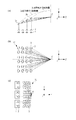
図3は、放物面ミラーアレイ30の機能を説明する図で、図3(a)はYZ断面への投影図であり、図3(b)はXZ断面への投影図であり、図3(c)はXY断面への投影図である。
3A and 3B are diagrams for explaining the function of the
なお、図3は放物面ミラーアレイ30の機能を説明するために、前述のミラーユニット40及び凹レンズ5等を省略し、図示していない。また、図3においては、2つの放物面ミラーアレイ30のうち、一方のみを図示している。
Note that FIG. 3 omits the
図3(a)に示すように、放物面ミラーアレイ30は、複数のコリメータレンズ2からの平行光束を収斂光束に変換し、放物面ミラーアレイ30からの収斂光束が焦点Fに集光していることがわかる。
As shown in FIG. 3A, the
すなわち、複数の放物面ミラー3は、複数のLD1からの複数の平行光束を複数の収斂光束に変換し、複数の収斂光束が複数の放物面ミラー3から離れるにつれて互いの距離を縮めるように複数のLD1からの複数の平行光束を反射する。
That is, the plurality of
言い換えれば、複数のLD1からの複数の光束の中心光線は、複数の放物面ミラー3を介して、凹レンズ5へ向かうにつれて互いの距離を縮めながら進む。
In other words, the central rays of the plurality of light fluxes from the plurality of
さらに言い換えると、複数のコリメータレンズ2の光軸を通る複数の光線は複数の放物面ミラー3を介して、凹レンズ5へ向かうにつれて互いの距離を縮めながら進む。また、図3(a)に示す通り、放物面ミラーアレイ30は、放物面ミラー3が収束する焦点Fが放物面ミラーアレイ30に対してLD1やコリメータレンズ2とは反対の側(Y方向が正の向き)に位置するように構成されていることが好ましい。これによって、焦点Fが放物面ミラーアレイに対してLD1やコリメータレンズ2と同じ側(Y方向の負の向き)に位置している場合と比較して、放物面ミラー3からの光束をより細くすることができる。言い換えれば、放物面ミラー3から射出される収斂光束の断面をいっそう細くすることができる。この結果、凹レンズ5からの光束の幅がより細くなり、後段の光学系をより小型にすることができる。
In other words, a plurality of light beams passing through the optical axes of the plurality of
上記の構成を言い換えれば、放物面ミラー3が、光源からの光束の主光線と放物面ミラー3が交差する位置における法線と、光源からの光束の主光線との成す角度が45度以上となるように構成されている。さらに言い換えれば、放物面ミラーアレイ30が、複数の放物面ミラー3からの複数の収斂光束に外接する円錐の中心線と、光源からの光束の主光線との成す角度が90度以上となるように構成されている。
In other words, the
なお、全ての放物面ミラー3が上記のように構成されている必要はない。複数の放物面ミラー3のうち少なくとも一つが上記の構成であればよく、さらには、複数の放物面ミラー3のうち半分以上が上記の構成であれば、より好ましい。すなわち、複数の放物面ミラー3のうち少なくとも1つの放物面ミラー3は、この放物面ミラー3からの光束が、この放物面ミラー3から離れるにつれて凹レンズ5に対して凹レンズ5の光軸方向に近づくように構成されていることが好ましい。
Note that it is not necessary that all the
放物面ミラー3は、放物面としての焦点は焦点Fで共通しているが、複数の放物面ミラー3が設けられている位置は互いに異なる。このため、複数の放物面ミラー3は互いに異なる形状をしており、形状を異ならせることで、複数の放物面ミラー3からの光束を焦点Fに集光させることが可能となる。
The
より具体的には、図3(a)に示すように、YZ断面において複数の放物面ミラー3のうち、最も凹レンズ5の光軸に近い放物面ミラー3aと、最も凹レンズ5の光軸から遠い放物面ミラー3bとで、その形状を比較する。両者の形状を比較すると、放物面頂点位置および近軸曲率半径が異なっていることがわかる。
More specifically, as shown in FIG. 3A, the
すなわち、放物面ミラー3aと放物面ミラー3bの頂点位置は互いに異なっているが、焦点位置は両者とも焦点Fで共通である。
That is, the apex positions of the
また、YZ断面において放物面ミラー3aと放物面ミラー3bは互いに異なる位置に設けられている。しかしながら、放物面ミラー3aと放物面ミラー3bの位置両者の焦点位置が焦点Fで共通となるようにするために、放物面ミラー3aと放物面ミラー3bの焦点距離は互いに異なっている。
In the YZ section, the
より具体的には、放物面ミラーアレイ30は、凹レンズ5の光軸から離れた位置に設けられている放物面ミラー3ほど、焦点距離が長くなるように構成されている。
More specifically, the
言い換えれば、放物面ミラーアレイ30は、放物面ミラー3b(第1の凹面鏡)と放物面ミラー3aよりもレンズユニットから離れている放物面ミラー3a(第2の凹面鏡)を含む。そして、放物面ミラー3aの焦点距離は放物面ミラー3bの焦点距離も長い。
In other words, the
仮に、複数の放物面ミラー3が全て同じ形状の放物面の一部である場合、複数の放物面ミラー3からの複数の収斂光束を一点に集光させることが困難になる。 If the plurality of paraboloid mirrors 3 are all part of the same shape of paraboloid, it is difficult to condense a plurality of convergent light beams from the plurality of paraboloid mirrors 3 at one point.
さらに、複数の放物面ミラー3が全て同じ形状の放物面の一部である場合に、複数の放物面ミラー3からの複数の収斂光束を一点に集光させるために、放物面ミラー3の位置を調整して複数の放物面ミラー3を繋げると、連続した形状の放物面となる。このような構成にすると、本実施例で示す構成と比較して、放物面ミラーアレイ30が大型化してしまうおそれがある。
Further, when the plurality of paraboloid mirrors 3 are all part of the same shape of paraboloid, the paraboloid surface is used to collect the plurality of convergent light beams from the plurality of paraboloid mirrors 3 at one point. When the position of the
また、放物面ミラーアレイ30が大型化すると、放物面ミラーアレイ30からの光束が太くなるために、ミラーユニット40や凹レンズ5も大型化するおそれがある。
Further, when the
仮に、ミラーユニット及び凹レンズを大型化させずに、連続した形状の放物面ミラーを用いる構成を考える。このような構成において、本実施例のように凹レンズの光軸を対称軸として左右に放物面ミラーを設けた場合には、左右の放物面ミラー間の間隔を本実施例に示す構成よりも大きくとる必要がある。このため、光源装置全体として大型化するおそれがある。 Let us consider a configuration in which a parabolic mirror having a continuous shape is used without increasing the size of the mirror unit and the concave lens. In such a configuration, when the parabolic mirrors are provided on the left and right with the optical axis of the concave lens as the axis of symmetry as in this embodiment, the interval between the left and right paraboloid mirrors is greater than the configuration shown in the present embodiment. Need to be larger. For this reason, there exists a possibility that it may enlarge as a whole light source device.
また、放物面ミラーが1つだけの場合には、本実施例に示す構成よりも、ミラーユニット及び凹レンズを放物面ミラーから離れた位置に設ける必要がある。このため、この場合には光源装置全体として大型化するおそれがある。 Further, when only one parabolic mirror is provided, it is necessary to provide the mirror unit and the concave lens at a position away from the parabolic mirror, as compared with the configuration shown in the present embodiment. For this reason, in this case, the entire light source device may be increased in size.
すなわち、本実施例のように、複数の放物面ミラー3が互いに異なる形状の放物面の一部であり、複数の放物面ミラー3のうち凹レンズ5から離れている放物面ミラー3ほど焦点距離が長いことで、前述の大型化を抑制することが可能となる。
That is, as in the present embodiment, the plurality of
なお、複数の放物面ミラー3が互いに異なる形状をしていることは、言い換えれば、複数の放物面ミラー3のそれぞれの焦点距離が互いに異なることを示す。
The plurality of
さらに、複数の放物面ミラー3のうち凹レンズ5から離れている放物面ミラー3ほど焦点距離が長いことは、言い換えれば、複数の放物面ミラー3のうち、複数のLD1に近い放物面ミラー3ほど焦点距離が長いことを示す。
Furthermore, the
なお、凹レンズ5から離れていることは、放物面ミラー3から凹レンズ5までの光路長が長いこと、凹レンズ5から離れた位置に設けられていること、あるいはその双方を満たすことを示す。
In addition, being away from the concave lens 5 indicates that the optical path length from the
さらに、本実施例で示す放物面ミラーアレイ30によれば、複数の放物面ミラー3からの複数の収斂光束を一点に集光させることが可能となり、蛍光体から出射する光束の平行度を高めることが可能となる。
Furthermore, according to the
ここで、凹レンズ5の光軸と、ミラーユニット40の長辺方向を含む面を第1断面とし、第1断面と直交し、凹レンズ5の光軸を含む面を第2断面とする。このとき、複数の放物面ミラー3のうち、第1断面あるいは第2断面を対称面として対称に設けられている放物面ミラー3同士(反射面同士)は、同じ形状の放物面形状の一部である。本実施例において、第1断面はXY断面であり、第2断面はYZ断面である。
Here, a surface including the optical axis of the concave lens 5 and the long side direction of the
言い換えれば、複数の放物面ミラー3のうち、XZ断面において凹レンズ5の光軸から等しい距離に位置する放物面ミラー3同士は、同じ形状の放物面形状の一部である。このように放物面ミラーアレイ30を構成することで、図2(a)に示すように、凹レンズ5の光軸を対称軸として左右に放物面ミラーアレイ30を設けた構成であっても、放物面ミラーアレイ30からの複数の収斂光束を一点に集光させることが可能となる。
In other words, among the plurality of
また、図4に示すように、放物面ミラーアレイ30は1つの光学素子として構成されている。具体的には、ベース部材6に複数の放物面ミラー3が不連続に設けられている構成となっている。言い換えれば、複数の放物面ミラー3が互いに所定の間隔を空けてベース部材6上に設けられている。なお、放物面ミラー3同士の間隔は、LD1の配列間隔に合わせている。
Further, as shown in FIG. 4, the
図4に示す光学素子である放物面ミラーアレイ30は、ガラス材料の成形によって形成しても良いし、金属部品の切削あるいは成形によって形成されても良い。
The
また、複数の放物面ミラー3が互いに異なる形状の放物面の一部であれば、複数の放物面ミラー3は図4に示すように不連続に形成されていても良い。
Further, if the plurality of
ここで、金型を用いたガラス成形によって放物面ミラーアレイ30を製造する場合、金型から放物面ミラーアレイ30を外す際に生じるダレの発生を抑制するためには、放物面ミラーアレイ30の凹凸が少ないことが望ましい。すなわち、ベース部材6から放物面ミラー3の端点までのY軸方向の距離が短いことが望ましい。
Here, when manufacturing the
このため、複数の放物面ミラー3間の隙間を、放物面ミラー3の端点を通るようなスプライン曲面等の滑らかな曲面のガラス材料や金属材料等で埋めることが望ましい。これにより、放物面ミラーアレイ30の表面の凹凸を少なくし、前述の成形時のダレを抑制することが可能となる。
For this reason, it is desirable to fill the gaps between the plurality of
なお、ベース部材6は平板状でなくても良く、例えば曲面状であっても良い。 Note that the base member 6 does not have to be flat, and may be curved, for example.
また、ベース部材6に放物面ミラー3を設ける構成ではなく、例えば平板の金属板をプレス成形することによって、厚みが一定でかつ複数の反射面を備える階段状の放物面ミラーアレイであっても良い。なお、放物面ミラー3の反射面にはコーティングがなされているが、そのコーティングはアルミや銀などの金属反射膜であっても、誘電体多層膜であっても良い。誘電体多層膜の場合には、LD1からの光束の波長で反射率が最大となる誘電体多層膜を用いることで、より光の利用効率を高めることが可能となる。
In addition, the
ここで、一般にLDは直線偏光光を射出しているが、LD1からの光束の偏光方向がX軸方向となるように複数のLD1を配置することで、YZ断面における放物面ミラー3での反射率が高まり、より光の利用効率を高めることが可能となる。
Here, in general, the LD emits linearly polarized light. However, by arranging a plurality of LD1 so that the polarization direction of the light beam from the LD1 is in the X-axis direction, the
図2(a)に示すようにYZ断面においては、Z軸方向に配列された複数のLD1からの複数の光束の全てがミラーユニット40へ入射できるようにするために、他の断面と比較して、複数のLD1からの光束をより急な角度で反射する必要がある。
As shown in FIG. 2A, in the YZ section, in order to allow all of the plurality of light beams from the plurality of
このため、LD1からの光束の偏光方向がX軸方向となるように複数のLD1を配置することで、YZ断面における放物面ミラー3での反射率を高めることが望ましい。
For this reason, it is desirable to increase the reflectance at the
また、各放物面ミラー3へのLD1からの光束の入射角度は、複数の放物面ミラー3ごとに異なっている。これは、後述のように、凹レンズ5の光軸から離れた位置に入射する光束をミラーユニット40へ導いている放物面ミラー3ほど、凹レンズ5の光軸と放物面ミラー3とのなす角度が小さくなるように、放物面ミラーアレイ30を構成しているためである。
Further, the incident angle of the light beam from the
したがって、各放物面ミラー3のコーティングを、各放物面ミラー3へのLD1からの光束の入射角度で反射率が最大となるように調節することで、より光の利用効率を高めることが可能となる。
Therefore, by adjusting the coating of each
ただし、本発明は、放物面ミラー3のコーティングを複数の放物面ミラー3ごとに調節する構成に限定されるものではなく、複数の放物面ミラー3のコーティングが全て同じであってもよい。
However, the present invention is not limited to the configuration in which the coating of the
このような構成の場合、所定の入射角度で反射率が最大となるコーティングではなく、反射率が最大となる入射角度の範囲をもつコーティングが好ましい。 In such a configuration, a coating having a range of incident angles at which the reflectivity is maximized is preferable instead of a coating having a maximum reflectivity at a predetermined incident angle.
なお、各放物面ミラー3へのLD1からの光束の入射角度とは、放物面ミラー3上で、LD1からの光束のうちコリメータレンズ2の光軸を通る光線が入射する位置での法線と、入射光線とがなす角度である。
The incident angle of the light beam from the
また、凹レンズ5の光軸と放物面ミラー3とのなす角度とは、放物面ミラー3の端点を結ぶ線分と、凹レンズ5の光軸とのなす角度としてもよい。さらに、放物面ミラー3上で、LD1からの光束のうちコリメータレンズ2の光軸を通る光線が入射する位置での接線と、凹レンズ5の光軸とのなす角度としてもよい。
The angle formed by the optical axis of the concave lens 5 and the
本実施例において複数のLD1は全て青色光を発するLDであるが、本発明はこれに限定されるものではない。
In this embodiment, the plurality of
例えば、複数のLD1は、青色光を発するLD,赤色光を発するLD、緑色光を発するLDを含む構成であっても良い。さらに、複数のLD1は、青色光を発するLDと赤色光を発するLDとで構成されていてもよい。
For example, the plurality of
このように、複数のLD1が互いに波長の異なる複数のLDを含む構成である場合には、複数の放物面ミラー3のコーティングを、LDからの波長に合わせて異なるものにしてもよい。さらに、複数のLD1が青色光、赤色光、緑色光を発するLDを含む構成である場合には、前述のダイクロイックミラー12及び蛍光体13を設けなくても良い。
Thus, when the plurality of
次に、ミラーユニット40からの光束が凹レンズ5を介して後段の系へ向かうまでを説明する。
Next, a description is given of the process until the light beam from the
放物面ミラーアレイ30からの複数の収斂光束は、ミラーユニット40によって反射されて、凹レンズ5へ入射する。
A plurality of convergent light beams from the
なお、凹レンズ5は、負のパワーを有し、複数のLD1からの光束が入射する側が凸のメニスカスレンズである。
The concave lens 5 is a meniscus lens having negative power and having a convex side on which light beams from a plurality of
前述のように、放物面ミラーアレイ30からの複数の収斂光束は、ミラーユニット40が無い場合には、図3(a)に示すように、共有の焦点Fへ集光する。
As described above, the plurality of convergent light beams from the
さらに、本実施例においては、図5に示しように、凹レンズ5の焦点をF´とするとき、ミラーユニット40からの複数の収斂光束は、凹レンズ5が無い場合に、焦点F´へ集光する。
Further, in this embodiment, as shown in FIG. 5, when the focal point of the concave lens 5 is F ′, a plurality of convergent light beams from the
すなわち、複数の放物面ミラー3の焦点と凹レンズ5の焦点とが重なっている。このように構成することで、凹レンズ5は、ミラーユニット40からの複数の収斂光束を複数の平行光束へ変換することが可能となる。
That is, the focal points of the plurality of
なお、凹レンズ5を球面レンズで構成する場合は球面収差が発生するため、凹レンズ5からの光束の平行度が低下する場合がある。 In addition, when the concave lens 5 is comprised with a spherical lens, since spherical aberration generate | occur | produces, the parallelism of the light beam from the concave lens 5 may fall.
このような場合には、複数の放物面ミラー3の焦点位置を、凹レンズ5による球面収差を相殺するようにずらすことで、凹レンズ5からの光束の平行度の低下を抑制することが可能である。
In such a case, it is possible to suppress a decrease in the parallelism of the light beam from the concave lens 5 by shifting the focal positions of the plurality of
具体的には、凹レンズ5の光軸から離れた位置に入射する光束をミラーユニット40へ導いている放物面ミラー3ほど、凹レンズ5の光軸と放物面ミラー3とのなす角度が小さくなるように、放物面ミラーアレイ30を構成している。言い換えれば、複数の放物面ミラー3のうち凹レンズ5から離れている放物面ミラー3ほど凹レンズ5の光軸と放物面ミラー3とのなす角度が小さくなるように、放物面ミラーアレイ30を構成している。
Specifically, the angle formed between the optical axis of the concave lens 5 and the
このように構成することで、前述の凹レンズ5による球面収差を抑制しつつ、複数の放物面ミラー3からの複数の収斂光束を、蛍光体上のより狭い範囲に集光させることが可能となる。
With such a configuration, it is possible to condense a plurality of convergent light beams from a plurality of
以上、本発明の好ましい実施例について説明したが、本発明はこれらの実施例に限定されないことはいうまでもなく、その要旨の範囲内で種々の変形及び変更が可能である。 The preferred embodiments of the present invention have been described above, but the present invention is not limited to these embodiments, and various modifications and changes can be made within the scope of the gist.
〔他の実施形態〕
前述した実施例では、凹レンズを用いて放物面ミラーアレイからの光束を平行光束にする構成、すなわち、レンズユニットが負のパワーを有する構成を例示したが、本発明はこれに限定されるものではない。光の利用効率の低下を抑制しつつ、より小型な光源装置を実現可能な光学装置であれば、例えば、ミラーユニット40からの光束の集光位置よりもY軸方向奥側に凸レンズを設けてもよい。すなわち、レンズユニットが正のパワーを有する構成であっても良い。このような構成の場合、凸レンズの焦点がミラーユニット40からの光束の集光位置になるように凸レンズを設ける。
[Other Embodiments]
In the above-described embodiment, the configuration in which the concave lens is used to convert the light beam from the parabolic mirror array into a parallel light beam, that is, the lens unit has a negative power, but the present invention is not limited thereto. is not. For example, an optical device capable of realizing a smaller light source device while suppressing a decrease in light utilization efficiency is provided with a convex lens on the far side in the Y-axis direction from the condensing position of the light beam from the
また、前述した実施例では、複数の反射面及び複数の凹面鏡として複数の放物面ミラー3を用いた構成を例示したが、本発明はこれに限定されるものではない。例えば、複数の反射面として複数の平面ミラーを用い、コリメータレンズ2と平面ミラーとの間に、コリメータレンズ2からの平行光束を収斂光束に変換する第2の正レンズを設け、平面ミラーに収斂光束を導く構成であってもよい。すなわち、複数の光源からの光束は平行光束に限定されるものではなく、複数の反射面も放物面を含む凹面鏡に限定されるものではない。
In the above-described embodiment, the configuration using the plurality of
3 放物面ミラー(反射面・凹面鏡)
3a 放物面ミラー(第2の凹面鏡)
3b 放物面ミラー(第1の凹面鏡)
5 凹レンズ(レンズユニット)
30 放物面ミラーアレイ(光学ユニット)
3 Parabolic mirror (reflective surface, concave mirror)
3a Parabolic mirror (second concave mirror)
3b Parabolic mirror (first concave mirror)
5 Concave lens (lens unit)
30 Parabolic mirror array (optical unit)
Claims (8)
レンズユニットと、
前記複数の反射面からの光束を前記レンズユニットに導くミラーユニットと、を備える光学装置であって、
前記複数の反射面は、前記複数の反射面で反射された光束が複数の収斂光束であり、前記複数の収斂光束が前記複数の反射面から離れるにつれて互いの距離を縮めるように構成されており、
前記複数の反射面は、複数の凹面鏡であって、
前記複数の凹面鏡は第1の凹面鏡と前記第1の凹面鏡よりも前記レンズユニットから離れた位置に設けられた第2の凹面鏡とを含み、
前記第2の凹面鏡の焦点距離は、前記第1の凹面鏡の焦点距離よりも長く、
前記第1の凹面鏡と前記第2の凹面鏡は互いに異なる形状の複数の凹面の各々の一部であり、
前記レンズユニットの光軸方向において、前記ミラーユニットは、前記第2の凹面鏡と前記レンズユニットとの間に設けられている、
ことを特徴とする光学装置。 An optical unit comprising a plurality of reflecting surfaces for reflecting light beams from a plurality of light sources ;
A lens unit;
A mirror unit that guides light beams from the plurality of reflecting surfaces to the lens unit,
The plurality of reflecting surfaces are configured such that the light beams reflected by the plurality of reflecting surfaces are a plurality of convergent light beams, and the distance between the plurality of convergent light beams decreases as the distance from the plurality of reflecting surfaces increases. ,
The plurality of reflecting surfaces are a plurality of concave mirrors,
The plurality of concave mirrors include a first concave mirror and a second concave mirror provided at a position farther from the lens unit than the first concave mirror,
The focal length of the second concave mirror is longer than the focal length of the first concave mirror,
Said first concave mirror and the second concave mirror Ri part der plurality of concave respective different shapes,
In the optical axis direction of the lens unit, the mirror unit is provided between the second concave mirror and the lens unit.
An optical device .
ことを特徴とする請求項1に記載の光学装置。 The concave surface is a paraboloid;
The optical apparatus according to claim 1.
ことを特徴とする請求項1または2に記載の光学装置。 The lens unit is configured to convert a plurality of convergent light beams from the mirror unit into a plurality of parallel light beams parallel to each other.
The optical device according to claim 1, wherein the optical device is an optical device.
ことを特徴とする請求項3に記載の光学装置。 The lens unit includes a meniscus lens having negative power and a convex side on which a light beam from the plurality of light sources is incident.
The optical apparatus according to claim 3 .
前記第1断面と直交し、前記レンズユニットの光軸と平行な面を第2断面とするとき、前記複数の反射面のうち、前記第1断面あるいは前記第2断面を対称面として対称に設けられている反射面同士は、同じ形状の放物面形状の一部である、
ことを特徴とする請求項3または4に記載の光学装置。 A plane parallel to the optical axis of the lens unit and the long side direction of the mirror unit is a first cross section,
When a surface perpendicular to the first cross section and parallel to the optical axis of the lens unit is a second cross section, the first cross section or the second cross section of the plurality of reflective surfaces is provided symmetrically with respect to the symmetry plane. The reflecting surfaces being a part of the parabolic shape of the same shape,
The optical device according to claim 3 or 4, characterized in that.
前記複数の光源からの複数の光束それぞれが入射する複数の正レンズと、
請求項3乃至5のいずれか1項に記載の光学装置と、
前記光学装置からの光束の一部を前記光学装置からの光束と波長が異なる変換光に変換するとともに、前記変換光と、前記光学装置からの光束と波長が同じ非変換光と、を射出する波長変換素子と、
ダイクロイックミラーと、を備え、
前記ダイクロイックミラーは、前記光学装置からの光束が前記ダイクロイックミラーを介して前記波長変換素子へ入射するように構成されている、
ことを特徴とする光源装置。 Multiple light sources;
A plurality of positive lenses on which a plurality of light beams from the plurality of light sources respectively enter;
An optical device according to any one of claims 3 to 5 ,
A part of the light beam from the optical device is converted into converted light having a wavelength different from that of the light beam from the optical device, and the converted light and non-converted light having the same wavelength as the light beam from the optical device are emitted. A wavelength conversion element;
A dichroic mirror, and
The dichroic mirror is configured such that a light beam from the optical device enters the wavelength conversion element via the dichroic mirror.
A light source device characterized by that.
光変調素子と、
前記光源装置からの光束を複数の光束に分割して前記光変調素子に導くとともに、前記光変調素子からの光束を合成する色分離合成系と、
前記光源装置からの光束を前記色分離合成系に導く照明光学系と、を備える、
ことを特徴とする投射型表示装置。 The light source device according to claim 6 ;
A light modulation element;
A light separation unit that divides a light beam from the light source device into a plurality of light beams and guides it to the light modulation element, and combines a light beam from the light modulation element;
An illumination optical system that guides a light beam from the light source device to the color separation / synthesis system,
A projection type display device characterized by that.
前記複数の反射面は、前記複数の反射面で反射された光束が複数の収斂光束であり、前記複数の収斂光束が前記複数の反射面から離れるにつれて互いの距離を縮めるように構成されており、The plurality of reflecting surfaces are configured such that the light beams reflected by the plurality of reflecting surfaces are a plurality of convergent light beams, and the distance between the plurality of convergent light beams decreases as the distance from the plurality of reflecting surfaces increases. ,
前記複数の反射面は、複数の凹面鏡であって、The plurality of reflecting surfaces are a plurality of concave mirrors,
前記複数の凹面鏡の各々は、互いに異なる形状の複数の凹面の各々の一部であり、Each of the plurality of concave mirrors is a part of each of a plurality of concave surfaces having different shapes,
前記複数の凹面鏡は第1の凹面鏡と前記第1の凹面鏡よりも前記レンズユニットから離れた位置に設けられた第2の凹面鏡とを含み、前記第2の凹面鏡の焦点距離は、前記第1の凹面鏡の焦点距離よりも長く、The plurality of concave mirrors include a first concave mirror and a second concave mirror provided at a position farther from the lens unit than the first concave mirror, and the focal length of the second concave mirror is the first concave mirror Longer than the focal length of the concave mirror,
前記レンズユニットの光軸及び前記ミラーユニットの長辺方向に平行な面を第1断面とし、A plane parallel to the optical axis of the lens unit and the long side direction of the mirror unit is a first cross section,
前記第1断面と直交し、前記レンズユニットの光軸と平行な面を第2断面とするとき、前記複数の反射面のうち、前記第1断面あるいは前記第2断面を対称面として対称に設けられている反射面同士は、同じ形状の放物面形状の一部である、When a surface perpendicular to the first cross section and parallel to the optical axis of the lens unit is a second cross section, the first cross section or the second cross section of the plurality of reflective surfaces is provided symmetrically with respect to the symmetry plane. The reflecting surfaces being a part of the parabolic shape of the same shape,
ことを特徴とする光学ユニット。An optical unit characterized by that.
Priority Applications (4)
| Application Number | Priority Date | Filing Date | Title |
|---|---|---|---|
| US14/868,190 US9864263B2 (en) | 2014-09-30 | 2015-09-28 | Optical unit, optical apparatus using the same, light source apparatus, and projection display apparatus |
| DE102015116447.7A DE102015116447B4 (en) | 2014-09-30 | 2015-09-29 | Optical unit, optical device using the same, light source device and projection display device |
| GB1517286.9A GB2531920B (en) | 2014-09-30 | 2015-09-30 | Optical unit, optical apparatus using the same, light source apparatus, and projection display apparatus |
| CN201510639227.5A CN105467736B (en) | 2014-09-30 | 2015-09-30 | Optical unit, Optical devices, light supply apparatus and projection display equipment using it |
Applications Claiming Priority (2)
| Application Number | Priority Date | Filing Date | Title |
|---|---|---|---|
| JP2014201811 | 2014-09-30 | ||
| JP2014201811 | 2014-09-30 |
Related Child Applications (1)
| Application Number | Title | Priority Date | Filing Date |
|---|---|---|---|
| JP2016195993A Division JP6604929B2 (en) | 2014-09-30 | 2016-10-03 | Optical unit, optical device using the same, light source device, and projection display device |
Publications (3)
| Publication Number | Publication Date |
|---|---|
| JP2016071353A JP2016071353A (en) | 2016-05-09 |
| JP2016071353A5 JP2016071353A5 (en) | 2016-08-12 |
| JP6072177B2 true JP6072177B2 (en) | 2017-02-01 |
Family
ID=55866798
Family Applications (2)
| Application Number | Title | Priority Date | Filing Date |
|---|---|---|---|
| JP2015176821A Active JP6072177B2 (en) | 2014-09-30 | 2015-09-08 | Optical unit, optical device, light source device using the same, and projection display device |
| JP2016195993A Active JP6604929B2 (en) | 2014-09-30 | 2016-10-03 | Optical unit, optical device using the same, light source device, and projection display device |
Family Applications After (1)
| Application Number | Title | Priority Date | Filing Date |
|---|---|---|---|
| JP2016195993A Active JP6604929B2 (en) | 2014-09-30 | 2016-10-03 | Optical unit, optical device using the same, light source device, and projection display device |
Country Status (1)
| Country | Link |
|---|---|
| JP (2) | JP6072177B2 (en) |
Families Citing this family (3)
| Publication number | Priority date | Publication date | Assignee | Title |
|---|---|---|---|---|
| JP6919266B2 (en) * | 2017-03-28 | 2021-08-18 | セイコーエプソン株式会社 | Light emitting device and image display system |
| US11152758B2 (en) * | 2018-09-06 | 2021-10-19 | Nichia Corporation | Light emitting device |
| JP6973457B2 (en) * | 2019-09-20 | 2021-12-01 | セイコーエプソン株式会社 | projector |
Family Cites Families (12)
| Publication number | Priority date | Publication date | Assignee | Title |
|---|---|---|---|---|
| US6523977B2 (en) * | 2001-02-20 | 2003-02-25 | Prokia Technology Co., Ltd. | Illuminating apparatus including a plurality of light sources that generate primary color light components |
| CN101393382A (en) * | 2007-09-18 | 2009-03-25 | 中强光电股份有限公司 | Projection display and light source module thereof |
| JP5157961B2 (en) * | 2009-02-27 | 2013-03-06 | ウシオ電機株式会社 | Light source device |
| JP5429543B2 (en) * | 2009-09-15 | 2014-02-26 | カシオ計算機株式会社 | Light source unit and projector |
| JP5500339B2 (en) * | 2009-09-29 | 2014-05-21 | カシオ計算機株式会社 | Light source device and projector |
| JP6202661B2 (en) * | 2011-09-28 | 2017-09-27 | カシオ計算機株式会社 | Light source device and projector |
| JP2013080578A (en) * | 2011-10-03 | 2013-05-02 | Seiko Epson Corp | Light source device and projector |
| JP5914808B2 (en) * | 2011-12-21 | 2016-05-11 | パナソニックIpマネジメント株式会社 | Light source device and projection display device |
| JP6295960B2 (en) * | 2012-11-06 | 2018-03-20 | ソニー株式会社 | Light source unit, light source device, and image display device |
| JP6178991B2 (en) * | 2013-01-24 | 2017-08-16 | パナソニックIpマネジメント株式会社 | Light source unit and light source module using the same |
| JP6186752B2 (en) * | 2013-03-01 | 2017-08-30 | カシオ計算機株式会社 | Light source device and projection device |
| JP2016018594A (en) * | 2014-07-04 | 2016-02-01 | 三菱電機株式会社 | Light source device and electrical apparatus |
-
2015
- 2015-09-08 JP JP2015176821A patent/JP6072177B2/en active Active
-
2016
- 2016-10-03 JP JP2016195993A patent/JP6604929B2/en active Active
Also Published As
| Publication number | Publication date |
|---|---|
| JP2017016155A (en) | 2017-01-19 |
| JP6604929B2 (en) | 2019-11-13 |
| JP2016071353A (en) | 2016-05-09 |
Similar Documents
| Publication | Publication Date | Title |
|---|---|---|
| EP3598229B1 (en) | Light source apparatus and projection system | |
| KR101321475B1 (en) | Coupling lens, illuminating device, and electronic device | |
| US9864263B2 (en) | Optical unit, optical apparatus using the same, light source apparatus, and projection display apparatus | |
| US9551917B2 (en) | Light source unit and projection display system using same | |
| JP6525856B2 (en) | Light source optical system and projection type display using the same | |
| US20180292070A1 (en) | Light guide component and light source device | |
| US10372028B2 (en) | Light source device and projection type display apparatus | |
| JP6414199B2 (en) | Color separation / synthesis prism and optical system and projector using the same | |
| WO2016035349A1 (en) | Laser optical device and image projection device | |
| US10209527B2 (en) | Illuminator and projector | |
| JP2015153889A (en) | laser combining optical device | |
| US11223806B2 (en) | Light source system, method for improving light efficiency thereof, and display device | |
| JP6604929B2 (en) | Optical unit, optical device using the same, light source device, and projection display device | |
| CN108073025B (en) | Projection device and illumination system | |
| JP2015145975A (en) | Light source device and projection type display device using the same | |
| US10634981B2 (en) | Light source device and projection type display apparatus | |
| US9851631B2 (en) | Light source optical system and projection display apparatus employing the same | |
| JP7086518B2 (en) | Light source optical system and projection type display device using this | |
| US11204544B2 (en) | Projector | |
| JP6790170B2 (en) | Light source optical system and projection type display device using this | |
| WO2020218036A1 (en) | Optical system | |
| JP2001290010A (en) | Color synthesis optical element and projection type image display device using the same | |
| CN109782515A (en) | The projection arrangement of light-source system and the application light-source system | |
| JP5581700B2 (en) | Coupling lens and projection type image display apparatus having the coupling lens | |
| RU2473933C1 (en) | Input/output lens, illumination device and electronic device |
Legal Events
| Date | Code | Title | Description |
|---|---|---|---|
| A521 | Request for written amendment filed |
Free format text: JAPANESE INTERMEDIATE CODE: A523 Effective date: 20160628 |
|
| A621 | Written request for application examination |
Free format text: JAPANESE INTERMEDIATE CODE: A621 Effective date: 20160628 |
|
| A871 | Explanation of circumstances concerning accelerated examination |
Free format text: JAPANESE INTERMEDIATE CODE: A871 Effective date: 20160628 |
|
| A975 | Report on accelerated examination |
Free format text: JAPANESE INTERMEDIATE CODE: A971005 Effective date: 20160721 |
|
| A131 | Notification of reasons for refusal |
Free format text: JAPANESE INTERMEDIATE CODE: A131 Effective date: 20160802 |
|
| A521 | Request for written amendment filed |
Free format text: JAPANESE INTERMEDIATE CODE: A523 Effective date: 20161003 |
|
| TRDD | Decision of grant or rejection written | ||
| A01 | Written decision to grant a patent or to grant a registration (utility model) |
Free format text: JAPANESE INTERMEDIATE CODE: A01 Effective date: 20161206 |
|
| A61 | First payment of annual fees (during grant procedure) |
Free format text: JAPANESE INTERMEDIATE CODE: A61 Effective date: 20161227 |
|
| R151 | Written notification of patent or utility model registration |
Ref document number: 6072177 Country of ref document: JP Free format text: JAPANESE INTERMEDIATE CODE: R151 |