JP6072017B2 - Dynamic constraints associated with optical shape sensing - Google Patents
Dynamic constraints associated with optical shape sensing Download PDFInfo
- Publication number
- JP6072017B2 JP6072017B2 JP2014514182A JP2014514182A JP6072017B2 JP 6072017 B2 JP6072017 B2 JP 6072017B2 JP 2014514182 A JP2014514182 A JP 2014514182A JP 2014514182 A JP2014514182 A JP 2014514182A JP 6072017 B2 JP6072017 B2 JP 6072017B2
- Authority
- JP
- Japan
- Prior art keywords
- mesh
- optical fibers
- shape sensing
- sensing optical
- sensor
- Prior art date
- Legal status (The legal status is an assumption and is not a legal conclusion. Google has not performed a legal analysis and makes no representation as to the accuracy of the status listed.)
- Expired - Fee Related
Links
Images


Classifications
-
- A—HUMAN NECESSITIES
- A61—MEDICAL OR VETERINARY SCIENCE; HYGIENE
- A61B—DIAGNOSIS; SURGERY; IDENTIFICATION
- A61B5/00—Measuring for diagnostic purposes; Identification of persons
- A61B5/05—Detecting, measuring or recording for diagnosis by means of electric currents or magnetic fields; Measuring using microwaves or radio waves
- A61B5/053—Measuring electrical impedance or conductance of a portion of the body
- A61B5/0536—Impedance imaging, e.g. by tomography
-
- A—HUMAN NECESSITIES
- A61—MEDICAL OR VETERINARY SCIENCE; HYGIENE
- A61B—DIAGNOSIS; SURGERY; IDENTIFICATION
- A61B34/00—Computer-aided surgery; Manipulators or robots specially adapted for use in surgery
- A61B34/20—Surgical navigation systems; Devices for tracking or guiding surgical instruments, e.g. for frameless stereotaxis
-
- A—HUMAN NECESSITIES
- A61—MEDICAL OR VETERINARY SCIENCE; HYGIENE
- A61B—DIAGNOSIS; SURGERY; IDENTIFICATION
- A61B5/00—Measuring for diagnostic purposes; Identification of persons
- A61B5/0033—Features or image-related aspects of imaging apparatus classified in A61B5/00, e.g. for MRI, optical tomography or impedance tomography apparatus; arrangements of imaging apparatus in a room
- A61B5/0036—Features or image-related aspects of imaging apparatus classified in A61B5/00, e.g. for MRI, optical tomography or impedance tomography apparatus; arrangements of imaging apparatus in a room including treatment, e.g., using an implantable medical device, ablating, ventilating
-
- A—HUMAN NECESSITIES
- A61—MEDICAL OR VETERINARY SCIENCE; HYGIENE
- A61B—DIAGNOSIS; SURGERY; IDENTIFICATION
- A61B5/00—Measuring for diagnostic purposes; Identification of persons
- A61B5/0059—Measuring for diagnostic purposes; Identification of persons using light, e.g. diagnosis by transillumination, diascopy, fluorescence
- A61B5/0062—Arrangements for scanning
- A61B5/0064—Body surface scanning
-
- A—HUMAN NECESSITIES
- A61—MEDICAL OR VETERINARY SCIENCE; HYGIENE
- A61B—DIAGNOSIS; SURGERY; IDENTIFICATION
- A61B5/00—Measuring for diagnostic purposes; Identification of persons
- A61B5/0059—Measuring for diagnostic purposes; Identification of persons using light, e.g. diagnosis by transillumination, diascopy, fluorescence
- A61B5/0073—Measuring for diagnostic purposes; Identification of persons using light, e.g. diagnosis by transillumination, diascopy, fluorescence by tomography, i.e. reconstruction of 3D images from 2D projections
-
- A—HUMAN NECESSITIES
- A61—MEDICAL OR VETERINARY SCIENCE; HYGIENE
- A61B—DIAGNOSIS; SURGERY; IDENTIFICATION
- A61B5/00—Measuring for diagnostic purposes; Identification of persons
- A61B5/01—Measuring temperature of body parts ; Diagnostic temperature sensing, e.g. for malignant or inflamed tissue
- A61B5/015—By temperature mapping of body part
-
- A—HUMAN NECESSITIES
- A61—MEDICAL OR VETERINARY SCIENCE; HYGIENE
- A61B—DIAGNOSIS; SURGERY; IDENTIFICATION
- A61B5/00—Measuring for diagnostic purposes; Identification of persons
- A61B5/103—Detecting, measuring or recording devices for testing the shape, pattern, colour, size or movement of the body or parts thereof, for diagnostic purposes
- A61B5/107—Measuring physical dimensions, e.g. size of the entire body or parts thereof
- A61B5/1073—Measuring volume, e.g. of limbs
-
- A—HUMAN NECESSITIES
- A61—MEDICAL OR VETERINARY SCIENCE; HYGIENE
- A61B—DIAGNOSIS; SURGERY; IDENTIFICATION
- A61B5/00—Measuring for diagnostic purposes; Identification of persons
- A61B5/103—Detecting, measuring or recording devices for testing the shape, pattern, colour, size or movement of the body or parts thereof, for diagnostic purposes
- A61B5/11—Measuring movement of the entire body or parts thereof, e.g. head or hand tremor, mobility of a limb
- A61B5/1126—Measuring movement of the entire body or parts thereof, e.g. head or hand tremor, mobility of a limb using a particular sensing technique
- A61B5/1128—Measuring movement of the entire body or parts thereof, e.g. head or hand tremor, mobility of a limb using a particular sensing technique using image analysis
-
- A—HUMAN NECESSITIES
- A61—MEDICAL OR VETERINARY SCIENCE; HYGIENE
- A61B—DIAGNOSIS; SURGERY; IDENTIFICATION
- A61B5/00—Measuring for diagnostic purposes; Identification of persons
- A61B5/68—Arrangements of detecting, measuring or recording means, e.g. sensors, in relation to patient
- A61B5/6801—Arrangements of detecting, measuring or recording means, e.g. sensors, in relation to patient specially adapted to be attached to or worn on the body surface
- A61B5/6802—Sensor mounted on worn items
- A61B5/6804—Garments; Clothes
-
- A—HUMAN NECESSITIES
- A61—MEDICAL OR VETERINARY SCIENCE; HYGIENE
- A61B—DIAGNOSIS; SURGERY; IDENTIFICATION
- A61B5/00—Measuring for diagnostic purposes; Identification of persons
- A61B5/68—Arrangements of detecting, measuring or recording means, e.g. sensors, in relation to patient
- A61B5/6801—Arrangements of detecting, measuring or recording means, e.g. sensors, in relation to patient specially adapted to be attached to or worn on the body surface
- A61B5/683—Means for maintaining contact with the body
- A61B5/6831—Straps, bands or harnesses
-
- A—HUMAN NECESSITIES
- A61—MEDICAL OR VETERINARY SCIENCE; HYGIENE
- A61N—ELECTROTHERAPY; MAGNETOTHERAPY; RADIATION THERAPY; ULTRASOUND THERAPY
- A61N5/00—Radiation therapy
- A61N5/10—X-ray therapy; Gamma-ray therapy; Particle-irradiation therapy
- A61N5/1048—Monitoring, verifying, controlling systems and methods
- A61N5/1049—Monitoring, verifying, controlling systems and methods for verifying the position of the patient with respect to the radiation beam
-
- A—HUMAN NECESSITIES
- A61—MEDICAL OR VETERINARY SCIENCE; HYGIENE
- A61N—ELECTROTHERAPY; MAGNETOTHERAPY; RADIATION THERAPY; ULTRASOUND THERAPY
- A61N5/00—Radiation therapy
- A61N5/10—X-ray therapy; Gamma-ray therapy; Particle-irradiation therapy
- A61N5/1048—Monitoring, verifying, controlling systems and methods
- A61N5/1064—Monitoring, verifying, controlling systems and methods for adjusting radiation treatment in response to monitoring
- A61N5/1069—Target adjustment, e.g. moving the patient support
-
- A—HUMAN NECESSITIES
- A61—MEDICAL OR VETERINARY SCIENCE; HYGIENE
- A61B—DIAGNOSIS; SURGERY; IDENTIFICATION
- A61B17/00—Surgical instruments, devices or methods, e.g. tourniquets
- A61B2017/00681—Aspects not otherwise provided for
- A61B2017/00694—Aspects not otherwise provided for with means correcting for movement of or for synchronisation with the body
- A61B2017/00699—Aspects not otherwise provided for with means correcting for movement of or for synchronisation with the body correcting for movement caused by respiration, e.g. by triggering
-
- A—HUMAN NECESSITIES
- A61—MEDICAL OR VETERINARY SCIENCE; HYGIENE
- A61B—DIAGNOSIS; SURGERY; IDENTIFICATION
- A61B34/00—Computer-aided surgery; Manipulators or robots specially adapted for use in surgery
- A61B34/20—Surgical navigation systems; Devices for tracking or guiding surgical instruments, e.g. for frameless stereotaxis
- A61B2034/2046—Tracking techniques
- A61B2034/2051—Electromagnetic tracking systems
-
- A—HUMAN NECESSITIES
- A61—MEDICAL OR VETERINARY SCIENCE; HYGIENE
- A61B—DIAGNOSIS; SURGERY; IDENTIFICATION
- A61B34/00—Computer-aided surgery; Manipulators or robots specially adapted for use in surgery
- A61B34/20—Surgical navigation systems; Devices for tracking or guiding surgical instruments, e.g. for frameless stereotaxis
- A61B2034/2046—Tracking techniques
- A61B2034/2061—Tracking techniques using shape-sensors, e.g. fiber shape sensors with Bragg gratings
-
- A—HUMAN NECESSITIES
- A61—MEDICAL OR VETERINARY SCIENCE; HYGIENE
- A61B—DIAGNOSIS; SURGERY; IDENTIFICATION
- A61B2503/00—Evaluating a particular growth phase or type of persons or animals
- A61B2503/20—Workers
-
- A—HUMAN NECESSITIES
- A61—MEDICAL OR VETERINARY SCIENCE; HYGIENE
- A61B—DIAGNOSIS; SURGERY; IDENTIFICATION
- A61B2505/00—Evaluating, monitoring or diagnosing in the context of a particular type of medical care
- A61B2505/07—Home care
-
- G—PHYSICS
- G02—OPTICS
- G02B—OPTICAL ELEMENTS, SYSTEMS OR APPARATUS
- G02B6/00—Light guides; Structural details of arrangements comprising light guides and other optical elements, e.g. couplings
- G02B6/02—Optical fibres with cladding with or without a coating
- G02B6/02057—Optical fibres with cladding with or without a coating comprising gratings
- G02B6/02076—Refractive index modulation gratings, e.g. Bragg gratings
- G02B6/02195—Refractive index modulation gratings, e.g. Bragg gratings characterised by means for tuning the grating
- G02B6/022—Refractive index modulation gratings, e.g. Bragg gratings characterised by means for tuning the grating using mechanical stress, e.g. tuning by compression or elongation, special geometrical shapes such as "dog-bone" or taper
Description
本願は、2011年6月10日に出願され、本書に参照により組み込まれる米国仮出願番号第61/495,862号による優先権利益を請求する。 This application claims priority benefit from US Provisional Application No. 61 / 495,862, filed June 10, 2011, which is incorporated herein by reference.
本願は、光学形状センシングに関し、より詳細には、医療アプリケーションに関して空間的に配置されたセンサアレイに適用される光学形状センシング制約条件を備えるシステム及び方法に関する。 The present application relates to optical shape sensing, and more particularly to systems and methods with optical shape sensing constraints applied to spatially arranged sensor arrays for medical applications.
電気的インピーダンス断層撮影(EIT)、拡散光学断層撮影(DOT)、体表電位マッピング(BSPM)等の非線形及び不良設定問題に対するソリューションは通常、未知の関心パラメータに対して測定に関する事前知識を利用する数値的方法を用いてアプローチされる。例は、前方計算(forward calculation)に関する有限要素モデリング及びユニークでステーブルな逆解を得る正規化された非線形ソルバーを含む。産業上の及び医療の撮像問題において遭遇する典型的なシナリオは、時間不変の場合基本的に3次元であり、動的な観測に関して4次元である。 Solutions to non-linear and fault setting problems such as electrical impedance tomography (EIT), diffuse optical tomography (DOT), body surface potential mapping (BSPM) typically utilize prior knowledge about the measurement for unknown parameters of interest Approached using numerical methods. Examples include finite element modeling for forward calculations and normalized nonlinear solvers that obtain unique and stable inverse solutions. A typical scenario encountered in industrial and medical imaging problems is essentially 3D when time invariant and 4D for dynamic observation.
意味がある逆解に到達するには、実験的なセットアップの源/検出器ジオメトリだけでなく関心対象物/ボリュームの3次元(3D)形状を知ることが重要である。DOTの場合、入力信号は、源からの距離と共に指数的に減衰する。対象物のジオメトリに対して適合可能な測定セットアップは、一般的な使用に関する厳密でサイズの大きいものより好ましい。EITの場合、電極は組織と接触する必要があり、例えば、呼吸運動といった患者の運動による力学が、測定ジオメトリにおいて説明される必要がある。画像再構成の精度は、3D形状が時間においてどのように変化するかに依存する。 To arrive at a meaningful inverse solution, it is important to know the three-dimensional (3D) shape of the object / volume of interest as well as the source / detector geometry of the experimental setup. In the case of DOT, the input signal decays exponentially with distance from the source. A measurement setup that can be adapted to the geometry of the object is preferred over the exact and large size for general use. In the case of EIT, the electrode needs to be in contact with the tissue, for example, the dynamics due to the patient's motion, such as respiratory motion, need to be described in the measurement geometry. The accuracy of image reconstruction depends on how the 3D shape changes in time.
現在では、逆問題のソリューションに組み込まれる追加的な事前知識の例は、非侵襲的電気生体構造マッピング/体表電位マッピング(BSPM)、EIT及びDOTに関するコンピュータ断層撮影(CT)又は磁気共鳴(MR)からの撮像データを含む。しかしながら、これらのデータセットは通常、時間において前もったポイントで取得され、非接触マッピング/EIT/DOTを伴う断層撮影反転に関する測定取得の間、関心構造に存在する力学を反映するものではない。 Currently, examples of additional prior knowledge incorporated into inverse problem solutions include non-invasive electrical anatomy / body surface potential mapping (BSPM), computed tomography (CT) or magnetic resonance (MR) for EIT and DOT ). However, these data sets are typically acquired at a pre-point in time and do not reflect the dynamics present in the structure of interest during measurement acquisition for tomographic inversion with contactless mapping / EIT / DOT.
外部ビーム放射線療法(XRT)は、線形アクセラレータ機械を用いて2次元ビームを介して供給される。XRTは主に、複数の方向から患者に供給される単一のビームの放射線から成る。この方向はしばしば、正面又は背面、及び両側である。治療は、シミュレータとして知られる特別に較正された診断X線機器上で計画又はシミュレーションされる。なぜなら、シミュレータが、線形アクセラレータ処理を再現し、所望の計画を実現するための放射線ビームの通常確立されている構成とそれらとを比較するからである。シミュレーションの目的は、治療されることになるボリュームを正確に目標とする又は局所化することである。XRTは、計画及び実行の間、器官変形についての情報から利益を得る。 External beam radiation therapy (XRT) is delivered via a two-dimensional beam using a linear accelerator machine. XRT mainly consists of a single beam of radiation delivered to a patient from multiple directions. This direction is often front or back and both sides. The treatment is planned or simulated on a specially calibrated diagnostic x-ray machine known as a simulator. This is because the simulator reproduces the linear accelerator process and compares them with the normally established configuration of the radiation beam to achieve the desired plan. The purpose of the simulation is to accurately target or localize the volume to be treated. XRT benefits from information about organ deformation during planning and execution.
形状情報は、種々のシステムから得られることができる。これらは、光学形状監視システム(例えば、ファイバー光学ブラッグセンサ、レイリー散乱、ブリュアン散乱、光学強度ベースの減衰)、装置上のポイントの電磁気(EM)ローカライゼーションのためのマルチコイルアレイ、3次元表面推定に関するレーザースキャンシステム、及び形状のカメラ(タイムオブフライト又は従来の光学測定)又はマイクベースの監視に関する光学/音響マーカー/エミッタアレイを含む。超音波のようなリアルタイム撮像も形状情報に関して用いられることができる。しかし、その手法の臨床生存度は、実行される撮像に対する断層撮影情報の追加的なコスト及び臨床値に依存する。 Shape information can be obtained from various systems. These relate to optical shape monitoring systems (eg fiber optic Bragg sensors, Rayleigh scattering, Brillouin scattering, optical intensity-based attenuation), multi-coil arrays for electromagnetic (EM) localization of points on the device, 3D surface estimation Includes laser scanning systems and optical / acoustic marker / emitter arrays for shape cameras (time-of-flight or conventional optical measurements) or microphone-based surveillance. Real-time imaging such as ultrasound can also be used for shape information. However, the clinical viability of the technique depends on the additional cost and clinical value of tomographic information for the performed imaging.
本発明によれば、対象物の動的な運動を測定するシステム、デバイス及び方法が、対象物の少なくとも部分にわたり柔軟に及びぴったりフィットするよう構成されるメッシュを含む。このメッシュは、1つ又は複数の形状センシング光学ファイバーと、センサ又は検出器を持つ測定の第2のモダリティとを含み、上記1つ又は複数の形状センシング光学ファイバーが、対象物における上記センサ又は検出器の運動を監視する。再構成モジュールは、上記形状センシングファイバーに結合され、フィードバック信号を受信し、上記フィードバック信号に基づき上記センサ又は検出器の形状及び位置における動的な変化を解釈する。再構成モジュールは、上記対象物における医療活動を改善するため、上記動的な変化を考慮する。 In accordance with the present invention, a system, device and method for measuring the dynamic motion of an object includes a mesh configured to flexibly and snugly fit over at least a portion of the object. The mesh includes one or more shape sensing optical fibers and a second modality of measurement with a sensor or detector, wherein the one or more shape sensing optical fibers are the sensors or detections in the object. Monitor vessel movement. A reconstruction module is coupled to the shape sensing fiber, receives a feedback signal, and interprets dynamic changes in the shape or position of the sensor or detector based on the feedback signal. The reconstruction module considers the dynamic changes to improve medical activity on the object.
対象物の動的な運動を測定するデバイスが、上記対象物の少なくとも部分にフィットするよう構成されるメッシュを含む。1つ又は複数の形状センシング光学ファイバーが、上記メッシュに含まれる。第2の測定モダリティが、上記メッシュに組み込まれる複数のセンサを含み、上記1つ又は複数の形状センシング光学ファイバーが、上記対象物の皮膚表面から直接に測定を実行するために上記第2のモダリティと連動して使用される。調整機構が、上記対象物の部分に対する上記メッシュの柔軟でぴったりした付着を可能にするため、上記メッシュ及び上記1つ又は複数の形状センシング光学ファイバーの調整を可能にするよう構成される。 A device for measuring the dynamic motion of an object includes a mesh configured to fit at least a portion of the object. One or more shape sensing optical fibers are included in the mesh. A second measurement modality includes a plurality of sensors incorporated into the mesh, and the one or more shape sensing optical fibers are configured to perform the measurement directly from the skin surface of the object. Used in conjunction with. An adjustment mechanism is configured to allow adjustment of the mesh and the one or more shape sensing optical fibers to allow a flexible and tight attachment of the mesh to the portion of the object.
対象物の動的な運動を測定する方法が、上記対象物の少なくとも部分にわたり柔軟にかつぴったりフィットするよう構成されるメッシュを提供するステップであって、上記メッシュが、1つ又は複数の形状センシング光学ファイバーと別のセンシング技術のセンサとを含む、ステップと、上記センサの運動及び位置を監視するため、上記1つ又は複数の形状センシング光学ファイバーから受信されるフィードバック信号を使用して、上記フィードバック信号に基づき、上記センサの上記運動及び位置における動的な変化を解釈することにより、上記対象物の上記部分の形状を再構成するステップと、上記対象物における医療活動を改善するため、上記測定された動的な変化を考慮するステップとを含む。 A method for measuring dynamic motion of an object provides a mesh configured to flexibly and snugly fit over at least a portion of the object, the mesh comprising one or more shape sensing Using a feedback signal received from the one or more shape-sensing optical fibers to monitor the movement and position of the sensors, including steps comprising an optical fiber and a sensor of another sensing technology. Reconstructing the shape of the portion of the object by interpreting dynamic changes in the movement and position of the sensor based on the signal, and measuring the measurement to improve medical activity on the object. Taking into account the dynamic changes made.
本開示におけるこれら及び他の目的、特徴及び利点は、添付の図面と共に参照される、その説明的な実施形態の以下の詳細な説明から明らかになる。 These and other objects, features and advantages of the present disclosure will become apparent from the following detailed description of illustrative embodiments thereof, taken in conjunction with the accompanying drawings.
本開示は、以下の図面を参照して好ましい実施形態の以下の説明を詳細に提供する。 The present disclosure provides in detail the following description of preferred embodiments with reference to the following drawings.
本発明によれば、測定システム及び方法は、関心対象物/ジオメトリに関して特異的に構成される適合可能で最適化されたセットアップを提供する。特に有益な実施形態において、形状センシング技術は、不良設定再構成問題に関する源検出器セットアップの形状及び位置情報を決定するために使用される。これは、適合的及び動的な測定セットアップに関する不良設定問題をモデル化し、及び解決するのを助ける。 In accordance with the present invention, the measurement system and method provides an adaptable and optimized setup that is specifically configured with respect to the object / geometry of interest. In a particularly useful embodiment, shape sensing techniques are used to determine the shape and position information of the source detector setup with respect to the failure setting reconstruction problem. This helps to model and solve bad configuration problems with adaptive and dynamic measurement setups.
特に有益な実施形態において、1つ又は複数の形状センシング光学ファイバーが、電気、熱又は他の測定センサを持つメッシュにおいて使用される。ファイバー及び他のセンサが、優れた結果を提供するために一緒に機能する。例えば、センサからのファイバー位置決めフィードバックは、例えば、例えば電気インピーダンス断層撮影、体表面電位/温度マッピング等の複数の異なる手順又は研究に関するより正確な結果を可能にするため、より正確なセンサ位置を提供する。光学形状センシングファイバーは、不良設定問題を解決するより完全な画像を作成するため、追加的な情報を提供することができる。 In a particularly beneficial embodiment, one or more shape sensing optical fibers are used in the mesh with electrical, thermal or other measurement sensors. Fiber and other sensors work together to provide excellent results. For example, fiber positioning feedback from the sensor provides a more accurate sensor position to allow more accurate results for multiple different procedures or studies, eg, electrical impedance tomography, body surface potential / temperature mapping, etc. To do. The optical shape sensing fiber can provide additional information to create a more complete image that solves the defect setting problem.
本発明が医療器具に関して説明される点を理解されたい。しかしながら、本発明の教示は、より広く、複雑な生物学的又は機械的なシステムを追跡又は解析するのに使用される任意の器具に対して適用可能である。特に、本発明は、生体系の内部追跡手順、例えば肺、消化管、排泄器官、血管等といった体のすべての領域における手順に適用可能である。図面に示される要素は、ハードウェア及びソフトウェアの様々な組合せにおいて実現されることができ、単一の要素又は複数の要素において組み合わせられることができる機能を提供することができる。 It should be understood that the present invention is described with respect to medical devices. However, the teachings of the present invention are applicable to any instrument used to track or analyze a broader, more complex biological or mechanical system. In particular, the present invention is applicable to internal tracking procedures of biological systems, such as procedures in all regions of the body such as lungs, gastrointestinal tract, excretory organs, blood vessels and the like. The elements shown in the drawings can be implemented in various combinations of hardware and software, and can provide functionality that can be combined in a single element or multiple elements.
図面に示されるさまざまな要素の機能は、専用のハードウェアの使用を介してというだけでなく、適切なソフトウェアに関連してソフトウェアを実行することができるハードウェアの使用を介して与えられることができる。プロセッサにより提供されるとき、この機能は、単一の専用のプロセッサにより、単一の共有プロセッサにより、又は複数の個別のプロセッサにより与えられることができる。個別のプロセッサの幾つかは、共有されることができる。更に、「プロセッサ」又は「コントローラ」という用語の明確な使用は、ソフトウェアを実行することができるハードウェアを排他的に参照するものとして解釈されるべきではなく、デジタル信号プロセッサ(「DSP」)ハードウェア、ソフトウェアを格納する読出し専用メモリ(「ROM」)、ランダムアクセスメモリ(「RAM」)及び不揮発性ストレージ等を暗に含むが、これらに限定されるものではない。 The functions of the various elements shown in the drawings may be given not only through the use of dedicated hardware, but also through the use of hardware that can execute the software in relation to the appropriate software. it can. When provided by a processor, this functionality can be provided by a single dedicated processor, by a single shared processor, or by multiple individual processors. Some of the individual processors can be shared. Furthermore, the explicit use of the terms “processor” or “controller” should not be construed as an exclusive reference to hardware capable of executing software, but rather digital signal processor (“DSP”) hardware. Hardware, read-only memory (“ROM”) for storing software, random access memory (“RAM”), non-volatile storage, and the like, but not limited to.
更に、本発明の原理、側面、実施形態及び特定の例を述べる本書におけるすべての記載は、その構造的及び機能的均等の範囲の両方を含むものとして意図される。更に、斯かる均等物が、現在既知の均等物だけでなく将来開発される均等物(即ち、構造に関係なく、同じ機能を実行すべく開発される任意の要素)の両方を含むものとして意図される。従って、例えば、本書に与えられるブロック図は、本開示の原理を実現する説明的なシステム要素及び/又は回路の概念表示を表すという点を当業者は理解されたい。同様に、任意のフローチャート、流れ図等は、コンピュータ可読媒体において実質的に表されるさまざまな処理を示し、従って、コンピュータ又はプロセッサが明示的に示されるかどうかに関係なく、斯かるコンピュータ又はプロセッサにより実行される点を理解されたい。 Further, all statements herein reciting principles, aspects, embodiments and specific examples of the invention are intended to include both structural and functional equivalents thereof. Further, such equivalents are intended to include both currently known equivalents as well as equivalents developed in the future (ie, any element developed to perform the same function regardless of structure). Is done. Thus, for example, those skilled in the art should appreciate that the block diagrams provided herein represent conceptual representations of illustrative system elements and / or circuits that implement the principles of the present disclosure. Similarly, any flowcharts, flowcharts, etc. illustrate various processes that are substantially represented in a computer-readable medium, and thus whether or not a computer or processor is explicitly indicated by such computer or processor. Please understand what is done.
更に、本発明の実施形態は、コンピュータ若しくは任意の命令実行システムによる使用又はこれに関連した使用のためのプログラムコードを提供する、計算機が使用可能な又はコンピュータ可読のストレージ媒体から、アクセス可能なコンピュータプログラムの形をとることができる。この説明のため、計算機が使用可能な又はコンピュータ可読ストレージ媒体は、命令実行システム、装置又はデバイスによる使用又はこれに関連した使用のためのプログラムを、包含、格納、通信、伝搬、又は輸送することができる任意の装置とすることができる。媒体は、電気、磁気、光学、電磁気、赤外線若しくは半導体システム(又は、装置若しくはデバイス)、又は伝搬媒体とすることができる。コンピュータ可読媒体の例は、半導体又はソリッドステートメモリ、磁気テープ、リムーバブルコンピュータディスケット、ランダムアクセスメモリ(RAM)、読出し専用メモリ(ROM)、リジッド磁気ディスク及び光学ディスクを含む。光学ディスクの現在の例は、読出し専用コンパクトディスク(CD―ROM)、読出し/書込みコンパクトディスク(CD―R/W)及びDVDを含む。 In addition, embodiments of the present invention provide a computer-usable or computer-readable storage medium that provides program code for use by or in connection with a computer or any instruction execution system. Can take the form of a program. For purposes of this description, a computer-usable or computer-readable storage medium includes, stores, communicates, propagates, or transports a program for use by or in connection with an instruction execution system, apparatus, or device. It can be any device that can. The medium can be an electrical, magnetic, optical, electromagnetic, infrared, or semiconductor system (or apparatus or device), or a propagation medium. Examples of computer readable media include semiconductor or solid state memory, magnetic tape, removable computer diskettes, random access memory (RAM), read only memory (ROM), rigid magnetic disks and optical disks. Current examples of optical discs include read-only compact discs (CD-ROM), read / write compact discs (CD-R / W) and DVDs.
以下、同様な符号が同じ又は類似する要素を表す図面を参照する。最初に図1を参照すると、医療手順を実行するシステム100が図式的に示される。システム100は、手順を監督及び管理するのに使用されるワークステーション又は端末112を含むことができる。手順は、例えば生検、切除、薬物の注射等を含む任意の手順を含むことができるが、これらに限定されるものではない。ワークステーション112は好ましくは、1つ又は複数のプロセッサ114とプログラム及びアプリケーションを格納するメモリ116とを含む。システム100の機能及び要素が1つ又は複数のワークステーション又はシステムに一体化されることができる点を理解されたい。
Reference will now be made to the drawings in which like numerals represent the same or similar elements. Referring initially to FIG. 1, a
メモリ116は、柔軟なメッシュ106からの電磁気、光学、音響等のフィードバック信号を解釈するよう構成される再構成モジュール115を格納することができる。メッシュ106は、既知のジオメトリ又は使用の前に初期化されるジオメトリで埋め込まれる、ファイバーセンサ、光学、音響、電気若しくは電磁気マーカー又はセンサを含むことができる。形状監視端末122は、関心表面にわたりマーカー/センサ分布を測定し、較正/参照断面及び測定断面に関するフィードバックを再構成モジュール115に供給する。形状監視モジュール122は、光学ファイバーセンサ104への/からの光を送信及び受信する。光学ファイバーセンサ104は、繊維における全体のファイバーセンサ長が、最小にのみ変化することができるという事実を説明しつつ、基礎になる繊維基板の伸縮を可能にするパターン(例えば、柔軟なメンブレン内に埋め込まれる2D螺旋状パターン又は2Dシヌソイドパターン)で、メッシュ106に編まれる又は他の態様で一体化される。ファイバー104は、対象物148の屈曲の間、ファイバーにおける圧力を提供するため、制御ポイントで局所的に固定される。複数の制御ポイントが、例えば、ファイバー先端で、メッシュに対する全ての自由度でファイバーを制約することができる。一方、他の制御ポイントは、メッシュが変形するときパターン化された構造における任意の全体の経路長変化を収容するため、ファイバーがメッシュパターンに対して自由にスライドすることができるよう、スライドに関する自由度を構成可能にすることができる。
再構成モジュール115は、医療手順、診断テスト等の間、イベント又は動的な発生を解釈するため、複数のデバイス又はシステムから複数の入力を受信する能力を含むことができる。医療撮像デバイス110及び/又は追跡モジュール117も、含まれることができ、再構成モジュール115に対する追加的なフィードバックを提供することができる。再構成モジュール115は、信号フィードバック(及び他の任意のフィードバック)を用いて、患者の体の動的な変化に関連付けられるエラー又は収差を考慮するよう構成される。
The
ある実施形態では、対象物148又は対象物148上の関心領域140は、柔軟なメッシュ106により覆われる又は制約される。柔軟なメッシュ106は、対象物148又は関心領域140の運動又は屈曲に対応して伸縮するよう構成されるファブリック又はネットを含むことができる。メッシュ106は、光学ファイバーセンシング以外の技術(例えば、電極、トラッカ等)を含むことができるメッシュ106内に及びこれにわたり分散される、1つ又は複数のセンサ108及び/又は検出器109を含むことができる。形状センシングファイバー104、センサ108及び/又は検出器109は、再構成モジュール115に対して位置、温度、電場情報、形状情報等をリレーして戻すよう構成される。例えば、メッシュ106は、患者148の中間部にわたり配置されることができる。その結果、呼吸サイクルの間、センサ108/検出器109が、腹部又は胸部の動的な形状変化を検出する。この情報は、ノード間の距離又はメッシュ106における位置における距離又は変化を計算する再構成モジュール115を用いて解釈されることができる。メッシュ屈折は、撮像デバイス110により撮られる画像における呼吸を考慮するため、又は医療手順の間の動作(呼気の際のデバイスの挿入等)のタイミング若しくは動的な変化に関して補償を必要とする他の任意のイベント若しくは動作のタイミングを支援するために採用されることができる。
In certain embodiments, object 148 or region of
メッシュ106が、動的な形状/位置データを集めるために対象物の生体構造の任意の部分に対して適用されることができる点を理解されたい。例えば、メッシュ106は、腕、脚、腹部、胸部、首、頭又はこれらの組み合わせにわたり配置されることができる。更に、メッシュ106は、異なる大きさの対象物、異なる大きさの付属物等に関して構成されるよう調整可能にされることができる。
It should be understood that the
メッシュ106は、手順を実行する臨床医を支援するため、医療手順の間に使用されることができる。例えば、医療デバイス102は、針、カテーテル、ガイドワイヤ、内視鏡、プローブ、ロボット、電極、フィルタデバイス、バルーンデバイス又は他の医療要素等を含むことができる。ワークステーション112は、撮像又は他の臨床データに対する形状センシング情報のレジストレーション及びフュージョンを自動的に実行する処理及び計算要素に加えて、撮像システム110を用いて対象物148の内部画像を表示するディスプレイ118を含むことができる。撮像システム110は、撮像モダリティを含むことができる。これは、例えば、超音波、フォト音響効果、磁気共鳴撮像(MRI)システム、蛍光透視システム、コンピュータ断層撮影(CT)システム、陽電子放出断層撮影(PET)、単光子放出コンピュータ断層撮影(SPECT)又は他のシステムを含む。撮像システム110は、リアルタイムに手術中の撮像データを集めるよう構成されることができる。撮像データは、ディスプレイ118に表示されることができる。ディスプレイ118は、ユーザがワークステーション112及びその要素及び機能と相互作用することを可能にする。これは、ユーザがワークステーション112と相互作用するのを可能にする、キーボード、マウス、ジョイスティック又は他の任意の周辺機器又はコントロールを含むことができるインタフェース120により、更に容易にされる。
The
手順の間、撮像デバイス110により収集される画像は、3次元(3D)の動的な患者の動き、呼吸等が原因で、補償される必要がある場合がある。斯かる運動は、関心対象物又は領域のより安定したリアルタイムディスプレイ画像を提供するため、表示された画像において説明されることができる。1つ又は複数の追跡デバイス又はカメラ107が、デバイス102に組み込まれることができる。その結果、追跡/撮像情報が検出されることができる。追跡デバイス107は、電磁気(EM)トラッカ、ファイバーオプティック追跡、ロボティック位置決めシステム、カメラ等を含むことができる。
During the procedure, the images collected by the
再構成モジュール115は、動的な変化による不一致を計算するため、又は画像間の動的な変化を説明するため、補償モデル又は位置決めアルゴリズムを使用することができる。(フィードバック信号を用いる)関心領域140及び/又はデバイス102のデジタルレンダリングは、動的な変化によって説明される収差及びエラーを伴い表示されることができる。デジタルレンダリングは、画像修正モジュールにより生成されることができる。
The
ある実施形態では、システム100は、人間の体の断層撮影画像を生成するため、データを取得し、患者の運動に適合的な放射線療法を実行する。再構成及び最適化アルゴリズムは、メッシュ106の形状追跡から得られる可変測定ジオメトリを考慮するため、再構成モジュール115により使用されることができる。この情報は、動的な変化に適合するよう信号を調整するため、コントローラモジュール126又は他のデバイスに適用されることができる。1つの例において、コントローラモジュール126は、手順又は検査の間に行われる活動のデータ収集、フィードバック又は実行を改善するため、動的な変化に基づき、様々なコントローラ、センサ、放射線源/ビーム等を制御するための制御信号を生成することができる。再構成モジュール115により計算される形状再構成の間のフィードバックループは、臨床システムにより、薬物、化学療法、放射線を管理し、筋肉活動を測定する等の際に使用されることができる柔軟なメッシュ106の3D形状に関する情報を動的に提供する。
In one embodiment, the
こうして、光学ファイバーセンシング104は、メッシュ106に配置される第2のモダリティノード、電極、追跡デバイス、源等に関する追加的な情報を提供する。ノード(例えば、センサ108、検出器109等)の相対的な距離は、時間に対して既知であり、このデータは、より正確な予測を行い、将来の線量/治療を推定し、測定の精度を決定する等のために使用されることができる。
Thus, the
図2を参照すると、ベスト202が、メッシュ106の特徴を含むメッシュ206から形成される。ベスト202は、好ましくは柔軟であり、対象物148にわたりぴったり適合する。センシングファイバー210は、ベスト202に一体化され、対象物148の胸部の形状を決定するために使用される。形状センシングモジュール220は、ファイバー210に問い合わせ、この情報は、例えば、逆問題に関する最適解に達するため対象物148の現実のジオメトリをモデル化するソルバーモジュール212において用いられる。センシングファイバー210は、対象物の体の周りで螺旋形になり、及び従って、ジオメトリの充分な画像を供給する、ベスト202に一体化される単一の光学ファイバーを含むことができる。センシングファイバー210は、ベスト202に一体化される複数のファイバーを含むこともできる。
Referring to FIG. 2, a
センシングファイバー210は、1つ又は複数のファイバー光学ブラッグ格子(FBG)を含むことができる。これは、光の特定の波長を反射し、他のすべてを透過させる光学ファイバーのセグメントである。これは、ファイバーコアにおいて屈折率の周期変化を加えることにより実現される。このコアは、波長特有の誘電体ミラーを生成する。FBGは、従って、特定の波長をブロックするインライン光学フィルタとして、又は波長特有の反射器として用いられることができる。
The
FBGの動作の後の基本的な原理は、屈折率が変化する各インタフェースでのフレネル反射である。いくつかの波長に対して、様々な期間の反射光が同調している。その結果、建設的干渉が、反射に関して存在し、結果的に、透過に関して、弱め合い干渉となる。ブラッグ波長は、温度だけでなく圧力に対して敏感である。これは、FBG格子が、ファイバー光学センサにおけるセンシング要素として用いられることができることを意味する。FBGセンサにおいて、ブラッグ波長におけるシフトΔλBがもたらされ、印加圧力(ε)及び温度における変化(ΔT)が原因によるブラッグ波長における相対的なシフト(ΔλB/λB)は、およそ
係数Csは、圧力の係数と呼ばれ、その大きさは、通常約0.8x10⁻⁶/μεであり、又は絶対的な量において約1pm/μεである。係数CTは、センサの温度感度を表し、熱拡張係数及び熱光学効果から成り立つ。その値は、約7x10−6/K(又は、絶対的な量で13pm/K)である。 The coefficient Cs is called the pressure coefficient, and its magnitude is usually about 0.8 × 10 −6 / με, or in absolute quantity about 1 pm / με. Coefficient C T represents the temperature sensitivity of the sensor, consists of a thermal expansion coefficient and thermal optical effect. Its value is about 7 × 10 −6 / K (or 13 pm / K in absolute quantity).
この技術の主な利点の1つは、様々なセンサ要素が、ファイバーの長さにわたり分散されることができる点にある。ある構造に埋め込まれるファイバーの長さに沿って様々なセンサ(ゲージ)に3又はこれ以上のコアを組み込むことは、長手方向位置の関数としての構造の湾曲の上昇を可能にし、及び従って、斯かる構造の3次元形式が正確に決定されることを可能にする。即ち、不良設定問題を制約するボリュームが決定される。 One of the main advantages of this technique is that various sensor elements can be distributed over the length of the fiber. Incorporating three or more cores into various sensors (gauges) along the length of the fiber embedded in a structure allows for an increase in the curvature of the structure as a function of longitudinal position, and thus Allows the three-dimensional form of such structures to be determined accurately. That is, a volume that restricts the defect setting problem is determined.
FBGに代わるものとして、従来の光学ファイバーにおける固有の後方散乱が利用されることができる。そのような手法は、標準的な単一モードの通信ファイバーにおけるレイリー散乱を用いることである。レイリー散乱は、ファイバーコアにおける屈折率のランダムな変動の結果として発生する。これらのランダム変動は、格子長に沿った振幅及び位相のランダム変動を持つブラッグ格子としてモデル化されることができる。単一の長さのマルチコアファイバーにおいて延在する3又はこれ以上のコアにおいてこの効果を用いることにより、関心表面の3D形状及び力学が追跡可能である。 As an alternative to FBG, the inherent backscatter in conventional optical fibers can be utilized. Such an approach is to use Rayleigh scattering in a standard single mode communication fiber. Rayleigh scattering occurs as a result of random fluctuations in the refractive index in the fiber core. These random variations can be modeled as a Bragg grating with random variations in amplitude and phase along the grating length. By using this effect in three or more cores extending in a single length multi-core fiber, the 3D shape and dynamics of the surface of interest can be tracked.
ある実施形態では、ベスト202は、体電位表面マップ(BPSM)に関する電極ベストを含むことができる。BPSMベスト202は、そこに含まれる複数の電極センサ/検出器208を含む。この実施形態において、体表面の位置情報を集めるため、センサ/検出器208が、データ取得システム222に接続される。このセットアップにおいて、電極208から集められるサンプリングされたデータは、対象物の力学のより正確な描写を提供するため、形状センシングモジュールから得られる幾何学的な制約条件と相関されることができる。こうして、例えば呼吸等の間の形状の動的な変化が、ソルバーモジュール212において考慮されることができ、再構成画像表現224を提供するため画像に相関されることができる。これは、対象物における任意の検出された運動を説明する。同じセットアップが、温度センシング、電場センシング、振動の研究等に関して使用されることができる。こうして、体又は対象物の動的な(移動する)又は静的なデジタルレンダリングが、解析又は検査に関する情報の完全なセットを提供するため、他のリアルタイム測定とともに提供される。
In some embodiments, the
図3を参照すると、別の実施形態では、メッシュ106、206は、例えば、トランクス、ブラ、頭蓋帽、靴下、手袋等の衣類の形式で製造されることができる。衣類は、弾性的なSpandexTM又は弾性衣類の他の形式を含むことができる。説明のため、衣服302は、胸部の拡散光学断層撮影(DOT)に関して構成されることができる。衣服302は、患者にぴったりフィットするよう適応的な大きさにされる調整機構304を含む。調整機構304は、サイズを調整するフック及びループコネクタ、バックル、弾性バンド、ジッパー、スナップ又は他の任意のデバイスを含むことができる。光学センシングファイバー306は、衣服302の組織に配置され、光学信号は、生体構造組織と直接接触する衣服302における位置に対して送信及び受信される。センシング及び光学断層撮影に関して、同じ又は異なるファイバーが使用されることができる(例えば、光学形状センシングに使用される単一モードファイバーの代わりに、アプリケーションに基づき、マルチモードファイバが、信号強度を上昇させるために必要とされる場合がある)。
Referring to FIG. 3, in another embodiment, the
1つの場合において、生体構造組織は胸部であり、ファイバーは、測定ジオメトリの形状センシング/追跡に関して用いられることができ(レイリー散乱)、又はマルチコアファイバーセットアップにおいて、ブラッグ格子を含むことができる追加的なコアファイバーが、形状推定に関する手段として用いられることができる。解剖学的に適応される衣服302の形状を決定する他のジオメトリを追跡技術が考慮されることができる。光学ファイバー306は、接続308を用いて衣服302に対して好ましくは局所的に結合又は接続される。これは、クロスステッチにより、角度の付いた光学ファイバーを用いることにより、衣服における蛇行構成において編まれる若しくはこの構成を備えることにより、又は粘着剤を使用することにより、実現されることができる。
In one case, the anatomical tissue is the breast and the fiber can be used for shape sensing / tracking of the measurement geometry (Rayleigh scattering) or can include a Bragg grating in a multi-core fiber setup. A core fiber can be used as a means for shape estimation. Other geometry tracking techniques that determine the shape of the
光学ファイバー306及び他のシステムを用いて集められるジオメトリデータの間の相乗効果を生み出すため、他のデバイス又は薬物が、衣服において使用されることができる点に留意されたい。1つの例において、衣服302は、胸部周りに配置され、そこに一体化される放射線源を含むことができる。胸部の運動は、胸部の領域において実際に受信される放射線量を評価するために使用されることができる。他の用途も、本書において想定される。
Note that other devices or drugs can be used in the garment to create a synergistic effect between the geometry data collected using
図4を参照すると、システム402は、放射線療法に関して示される。対象物148は、放射線療法で治療される必要のある病巣又は腫瘍406を持つ。健康な組織を破壊するリスクを減らすため、患者動力学を考慮することが、重要である。光学センシングファイバー404を持つメッシュ106を使用することにより、患者動力学が説明されることができる。源412からの放射線ビーム410は、センシングファイバー404を用いて測定される動力学に基づき、パルス化又は他の態様で計時されることができる。別の実施形態では、コントローラ415は、例えばサーボモータ、アクチュエータ、デジタル信号プロセッサ、シャッタ等のデバイス420を制御する。これは、患者動力学データに基づき源412を動かし又はビーム410を方向付ける/制御するために使用されることができる。これは、放射線パルスのタイミングを制御し、及び/又はターゲット組織(例えば、腫瘍406)により正確に当たるよう、パルスの狙いを定めることを生じさせることができる。患者動力学データは、より高度なシステム制御のため患者モデルを駆動するのに用いられることができる。
Referring to FIG. 4,
本発明が説明的で非限定的な例(例えば、撮像技術、放射線療法等)に基づき説明されたが、他の用途が、本書において説明される本発明の概念から利益を得ることができる。例えば、本発明は、不良設定問題を解決するのに使用されることができる。不良設定問題は、最終的なデータから推測されるソリューションを持つ問題として説明されることができる(即ち、このソリューションは、最終的なデータにおける変化に対して非常に敏感である)。本発明は、逆問題を解決するのに使用されることができる。これは、関心物理対象物又は関心システムに関する情報へと観測された測定を変換するのに使用される一般的な枠組みを含む。例えば、このソリューションは、データとマッチングするために得られる。本発明は、温度マッピング、ニューロン撮像(例えば、脳磁気図検査/脳波記録法(MEG/EEG))、筋肉屈曲の測定等において使用されることができる。 Although the present invention has been described on the basis of descriptive and non-limiting examples (eg, imaging techniques, radiation therapy, etc.), other applications can benefit from the inventive concepts described herein. For example, the present invention can be used to solve a failure setting problem. A bad configuration problem can be described as a problem with a solution that is inferred from the final data (ie, this solution is very sensitive to changes in the final data). The present invention can be used to solve the inverse problem. This includes the general framework used to convert the observed measurements into information about the physical object of interest or system of interest. For example, this solution is obtained to match data. The present invention can be used in temperature mapping, neuronal imaging (eg, magnetoencephalography / electroencephalography (MEG / EEG)), muscle flexion measurement, and the like.
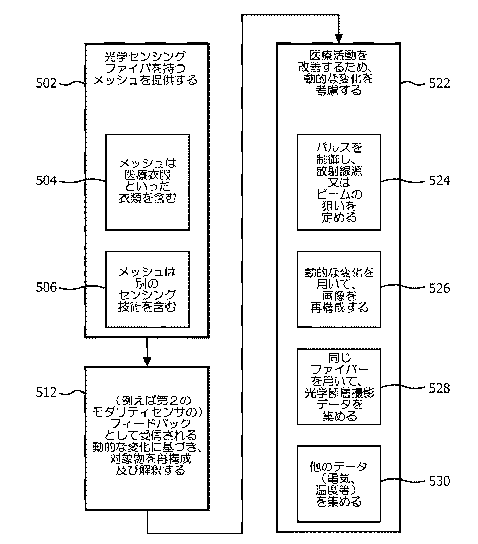
図5を参照すると、対象物の動的な運動を測定する方法が、説明的な実施形態による実例として示される。ブロック502において、メッシュが提供される。これは例えば、腕、脚、胸部等の対象物の少なくとも部分にわたり柔軟かつぴったりフィットするよう構成される。メッシュは、そこに配置される1つ又は複数の形状センシング光学ファイバーを含む。光学ファイバーは、メッシュの組織に織り込まれ、好ましくは、メッシュを撓曲させることがファイバーにおける圧力を与えるよう、メッシュファブリックに取り付けられる。光学ファイバーは、屈曲を可能にするが、対象物の部分の運動を制約するよう、メッシュに結ばれる、接着される又は、メッシュに対して他の態様で結合されることができる。ブロック504において、メッシュは、衣料品、そこに配置される検出器で位置検出を実行するよう構成される医療衣服を含むことができる。この場合、1つ又は複数の形状センシング光学ファイバーは、センサ、検出器等の位置検出を改善する、又は対象物における動的な変化を他の態様で測定するために使用される。
Referring to FIG. 5, a method for measuring the dynamic motion of an object is shown by way of illustration according to an illustrative embodiment. At
ブロック506において、好ましい実施形態において、メッシュは、ファイバー光学センシングと連動して使用される別のセンシングモダリティを含む。例えば、ファイバー光学センサにより囲まれる又はこれに一体化されるセンサ又は電極が使用されることができる。こうして、患者及び/又はセンサ若しくは電極の動き又は変位に関するフィードバックが、ファイバー光学センシングデータにより強化される。
At
ブロック512において、対象物の部分の形状が、1つ又は複数の形状センシングファイバーから受信されるフィードバック信号を使用することにより再構成され、メッシュの形状及び位置における動的な変化が、フィードバック信号に基づき解釈される。
At
ブロック522において、測定される動的な変化は、例えば治療、診断、解析といった例えば、メッシュにおいて組み込まれる第2のモダリティの対象物における医療活動を改善するために考慮される。例は、以下の通りである。ブロック524において、対象物を治療する放射線ビームのパルス及び/又は照準が、動的な変化に基づき制御される。ビームは、時間において変調され、又は健康な組織を破壊することなしに病巣又は腫瘍を破壊するためにその焦点をターゲット上に保つために移動される。ブロック526において、対象物の運動が原因による望ましくないアーチファクトなしに画像のより正確な測定又はレンダリングを提供するため、動的な変化に基づき画像が再構成される。ブロック528において、対象物の光学断層撮影データ又は他のデータが、同じ(又は、異なる)形状センシング光学ファイバーを用いて集められることができる。ブロック530において、電場データ、熱データ又は他のデータが集められる。収集されたデータは、形状センシング光学ファイバー情報に関して整合又は考慮される。例えば、1つ又は複数の形状センシング光学ファイバーが、電気インピーダンス断層撮影又は体表面電位/温度マッピングを実行するため、電気又は熱測定と共に用いられる。
At
添付の特許請求の範囲を解釈するにあたり、以下の点を理解されたい。 In interpreting the appended claims, it should be understood that:
a)「有する」という語は、所与の請求項に記載される要素又は行為以外の他の要素又は行為の存在を除外するものではない。 a) the word “comprising” does not exclude the presence of other elements or acts than those listed in a given claim;
b)ある要素に先行する「a」又は「an」という語は、斯かる要素が複数存在することを除外するものではない。 b) The word “a” or “an” preceding an element does not exclude the presence of a plurality of such elements.
c)請求項における任意の参照符号は、それらの範囲を制限するものではない。 c) any reference signs in the claims do not limit their scope;
d)複数の「手段」が、同じアイテム、又はハードウェア、又はソフトウェア実現による構造、又は機能により表されることができる。 d) Multiple “means” can be represented by the same item, or hardware or software implemented structure or function.
e)特に指定がない限り、行為の特定のシーケンスが必要とされること意図するものではない。 e) It is not intended that a specific sequence of actions is required unless otherwise specified.
光学形状センシングを用いる動的な制約(これは、説明的で非限定的なものとして意図される)のためのシステム及び方法に関する好ましい実施形態が上述されたが、修正及び変更が、上記の教示を考慮して当業者によりなされることができる点に留意されたい。従って、添付の特許請求の範囲により概説される開示された実施形態の範囲に含まれるものとして、本開示の特定の実施形態において変更がなされることができる点を理解されたい。こうして、本開示の内容が特許法により必要とされる範囲で詳細に記載されてきたが、特許証により保護されることを望む保護の請求は、添付の特許請求の範囲に記載される。 While preferred embodiments of systems and methods for dynamic constraints using optical shape sensing (which are intended as illustrative and non-limiting) have been described above, modifications and changes have been made to the above teachings. Note that this can be done by one skilled in the art in view of Accordingly, it should be understood that changes may be made in particular embodiments of the present disclosure as included within the scope of the disclosed embodiments outlined by the appended claims. Thus, while the content of the present disclosure has been described in detail to the extent required by patent law, claims for protection that are desired to be protected by Letters Patent are set forth in the appended claims.
Claims (15)
前記対象物の少なくとも部分にわたり柔軟にかつぴったりフィットするよう構成されるメッシュであって、1つ又は複数の形状センシング光学ファイバーと、センサ又は検出器を持つ測定の第2のフィードバックモダリティとを含み、前記1つ又は複数の形状センシング光学ファイバーが、前記対象物における前記センサ又は検出器の運動を監視する、メッシュと、
フィードバック信号を受信し、前記フィードバック信号に基づき前記センサ又は検出器の形状及び位置における動的な変化を解釈する、前記形状センシングファイバーに結合される再構成モジュールであって、前記対象物における医療活動を改善するため、前記動的な変化を考慮する、再構成モジュールとを有する、システム。 A system for measuring the dynamic motion of an object,
A mesh configured to flexibly and snugly fit over at least a portion of the object, comprising one or more shape sensing optical fibers and a second feedback modality of measurement with a sensor or detector; A mesh, wherein the one or more shape sensing optical fibers monitor movement of the sensor or detector in the object;
A reconstruction module coupled to the shape sensing fiber that receives a feedback signal and interprets dynamic changes in the shape and position of the sensor or detector based on the feedback signal, the medical activity on the object A reconfiguration module that takes into account the dynamic changes to improve the system.
前記対象物の少なくとも部分にフィットするよう構成されるメッシュと、
前記メッシュに含まれる1つ又は複数の形状センシング光学ファイバーと、
前記メッシュに組み込まれる複数のセンサを含む第2の測定モダリティであって、前記1つ又は複数の形状センシング光学ファイバーが、前記対象物の皮膚表面から直接に測定を実行するために前記第2のモダリティと連動して使用される、第2の測定モダリティと、
前記対象物の部分に対する前記メッシュの柔軟でぴったりした付着を可能にするため、前記メッシュ及び前記1つ又は複数の形状センシング光学ファイバーの調整を可能にするよう構成される調整機構とを有する、デバイス。 A device for measuring the dynamic movement of an object,
A mesh configured to fit at least a portion of the object;
One or more shape sensing optical fibers included in the mesh;
A second measurement modality comprising a plurality of sensors incorporated into the mesh, wherein the one or more shape sensing optical fibers are used to perform measurements directly from the skin surface of the object. A second measurement modality used in conjunction with the modality;
An adjustment mechanism configured to allow adjustment of the mesh and the one or more shape-sensing optical fibers to allow a flexible and snug attachment of the mesh to a portion of the object. .
前記対象物の少なくとも部分にわたり柔軟にかつぴったりフィットするよう構成されるメッシュを提供するステップであって、前記メッシュが、1つ又は複数の形状センシング光学ファイバーと別のセンシング技術のセンサとを含む、ステップと、
前記センサの運動及び位置を監視するため、前記1つ又は複数の形状センシング光学ファイバーから受信されるフィードバック信号を使用して、前記フィードバック信号に基づき、前記センサの前記運動及び位置における動的な変化を解釈することにより、前記対象物の前記部分の形状を再構成するステップと、
前記対象物における医療活動を改善するため、前記測定された動的な変化に基づき処理するステップとを有する、方法。 In a method of operating a system for measuring the dynamic motion of an object,
Providing a mesh configured to flexibly and snugly fit over at least a portion of the object, the mesh including one or more shape sensing optical fibers and another sensing technology sensor; Steps,
Dynamic changes in the motion and position of the sensor based on the feedback signal using feedback signals received from the one or more shape sensing optical fibers to monitor the motion and position of the sensor Reconstructing the shape of the portion of the object by interpreting
Processing based on the measured dynamic change to improve medical activity on the object.
パルスを制御し、前記対象物を治療するための放射線ビームの狙いを定めるステップ、
前記動的な変化に基づき、画像を再構成するステップ、又は
電気インピーダンス断層撮影又は体表面電位/温度マッピングを実行するため、電気又は熱測定を実行するステップの少なくとも1つを含む、請求項13に記載の方法。 Considering the measured dynamic change to improve the medical activity
Controlling a pulse and aiming a radiation beam to treat the object;
14. At least one of: reconstructing an image based on the dynamic change; or performing an electrical or thermal measurement to perform electrical impedance tomography or body surface potential / temperature mapping. The method described in 1.
Applications Claiming Priority (5)
| Application Number | Priority Date | Filing Date | Title |
|---|---|---|---|
| US201161495862P | 2011-06-10 | 2011-06-10 | |
| US61/495,862 | 2011-06-10 | ||
| US201161514585P | 2011-08-03 | 2011-08-03 | |
| US61/514,585 | 2011-08-03 | ||
| PCT/IB2012/052753 WO2012168836A2 (en) | 2011-06-10 | 2012-05-31 | Dynamic constraining with optical shape sensing |
Publications (3)
| Publication Number | Publication Date |
|---|---|
| JP2014525764A JP2014525764A (en) | 2014-10-02 |
| JP2014525764A5 JP2014525764A5 (en) | 2015-06-11 |
| JP6072017B2 true JP6072017B2 (en) | 2017-02-01 |
Family
ID=46384432
Family Applications (1)
| Application Number | Title | Priority Date | Filing Date |
|---|---|---|---|
| JP2014514182A Expired - Fee Related JP6072017B2 (en) | 2011-06-10 | 2012-05-31 | Dynamic constraints associated with optical shape sensing |
Country Status (5)
| Country | Link |
|---|---|
| US (1) | US20140088377A1 (en) |
| EP (1) | EP2717774B1 (en) |
| JP (1) | JP6072017B2 (en) |
| CN (1) | CN103607949B (en) |
| WO (1) | WO2012168836A2 (en) |
Families Citing this family (40)
| Publication number | Priority date | Publication date | Assignee | Title |
|---|---|---|---|---|
| JP6457262B2 (en) | 2011-03-30 | 2019-01-23 | アヴィザル,モルデチャイ | Method and system for simulating surgery |
| CN111282164A (en) | 2012-03-26 | 2020-06-16 | 皇家飞利浦有限公司 | System for planning radiation treatment therapy |
| CN104334085A (en) * | 2012-05-24 | 2015-02-04 | 皇家飞利浦有限公司 | Image generation apparatus |
| JP6343606B2 (en) * | 2012-05-25 | 2018-06-13 | サージカル シアター エルエルシー | Scene renderer with hybrid image / hands-free control |
| WO2014009853A2 (en) | 2012-07-09 | 2014-01-16 | Koninklijke Philips N.V. | Method and system for adaptive image guided intervention |
| US10159440B2 (en) | 2014-03-10 | 2018-12-25 | L.I.F.E. Corporation S.A. | Physiological monitoring garments |
| US8945328B2 (en) | 2012-09-11 | 2015-02-03 | L.I.F.E. Corporation S.A. | Methods of making garments having stretchable and conductive ink |
| US11246213B2 (en) | 2012-09-11 | 2022-02-08 | L.I.F.E. Corporation S.A. | Physiological monitoring garments |
| US8948839B1 (en) | 2013-08-06 | 2015-02-03 | L.I.F.E. Corporation S.A. | Compression garments having stretchable and conductive ink |
| US10462898B2 (en) | 2012-09-11 | 2019-10-29 | L.I.F.E. Corporation S.A. | Physiological monitoring garments |
| US10201310B2 (en) | 2012-09-11 | 2019-02-12 | L.I.F.E. Corporation S.A. | Calibration packaging apparatuses for physiological monitoring garments |
| WO2014041032A1 (en) | 2012-09-11 | 2014-03-20 | L.I.F.E. Corporation S.A. | Wearable communication platform |
| US9817440B2 (en) | 2012-09-11 | 2017-11-14 | L.I.F.E. Corporation S.A. | Garments having stretchable and conductive ink |
| JP6385929B2 (en) * | 2013-07-02 | 2018-09-05 | 学校法人北里研究所 | EIT measuring apparatus, EIT measuring method and program |
| WO2015025113A1 (en) * | 2013-08-20 | 2015-02-26 | Khor Joo Moy | Apparatus and method for estimating shape |
| US9216004B2 (en) | 2013-09-12 | 2015-12-22 | Jesse Talant | Adam and ease mammography device |
| EP3043738B1 (en) * | 2013-09-12 | 2019-12-11 | Intuitive Surgical Operations, Inc. | Shape sensor systems for localizing movable targets |
| WO2015103620A1 (en) | 2014-01-06 | 2015-07-09 | Andrea Aliverti | Systems and methods to automatically determine garment fit |
| US10912523B2 (en) * | 2014-03-24 | 2021-02-09 | Intuitive Surgical Operations, Inc. | Systems and methods for anatomic motion compensation |
| CN105992996B (en) | 2014-04-04 | 2019-11-26 | 外科手术室公司 | Dynamic and interactive navigation in surgical environment |
| US10850121B2 (en) | 2014-11-21 | 2020-12-01 | The Regents Of The University Of California | Three-dimensional radiotherapy dose distribution prediction |
| WO2016092388A1 (en) * | 2014-12-10 | 2016-06-16 | Koninklijke Philips N.V. | Guiding tracked shape reconstruction for interventional procedures |
| KR102593337B1 (en) | 2015-07-20 | 2023-10-23 | 엘.아이.에프.이. 코포레이션 에스.에이. | Flexible fabric ribbon connectors for clothing with sensors and electronics |
| WO2017066373A1 (en) | 2015-10-14 | 2017-04-20 | Surgical Theater LLC | Augmented reality surgical navigation |
| CN109640820A (en) | 2016-07-01 | 2019-04-16 | 立芙公司 | The living things feature recognition carried out by the clothes with multiple sensors |
| US10861236B2 (en) | 2017-09-08 | 2020-12-08 | Surgical Theater, Inc. | Dual mode augmented reality surgical system and method |
| WO2019060298A1 (en) | 2017-09-19 | 2019-03-28 | Neuroenhancement Lab, LLC | Method and apparatus for neuroenhancement |
| US11717686B2 (en) | 2017-12-04 | 2023-08-08 | Neuroenhancement Lab, LLC | Method and apparatus for neuroenhancement to facilitate learning and performance |
| WO2019133997A1 (en) | 2017-12-31 | 2019-07-04 | Neuroenhancement Lab, LLC | System and method for neuroenhancement to enhance emotional response |
| US11364361B2 (en) | 2018-04-20 | 2022-06-21 | Neuroenhancement Lab, LLC | System and method for inducing sleep by transplanting mental states |
| EP3849410A4 (en) | 2018-09-14 | 2022-11-02 | Neuroenhancement Lab, LLC | System and method of improving sleep |
| US10973579B2 (en) | 2018-12-28 | 2021-04-13 | Industrial Technology Research Institute | Optical system |
| US11786694B2 (en) | 2019-05-24 | 2023-10-17 | NeuroLight, Inc. | Device, method, and app for facilitating sleep |
| JP7349129B2 (en) | 2019-07-22 | 2023-09-22 | 国立大学法人千葉大学 | Visualization device for biological substances |
| GB201913032D0 (en) * | 2019-09-10 | 2019-10-23 | John Florence Ltd | Product for generating a three-dimensional shape and its use in the fabrication of custom orthosis |
| US11504010B2 (en) | 2019-12-20 | 2022-11-22 | EmpNia Inc. | Wearable health monitoring device |
| US11041740B1 (en) * | 2019-12-20 | 2021-06-22 | EmpNia Inc. | Method and apparatus for real time respiratory gating signal generation and detection of body deformation using embedded fiber Bragg gratings |
| CN111329587A (en) * | 2020-02-19 | 2020-06-26 | 上海理工大学 | Surgical registration system using shape sensing fiber optic mesh |
| CN112957621B (en) * | 2021-02-01 | 2022-04-22 | 南京航空航天大学 | Boron neutron capture therapy positioning and respiration monitoring system and method for applying same |
| US20230225674A1 (en) * | 2022-01-19 | 2023-07-20 | Lilu Inc. | Sensor-based garment for monitoring of breast milk production |
Family Cites Families (11)
| Publication number | Priority date | Publication date | Assignee | Title |
|---|---|---|---|---|
| CA2073162C (en) * | 1991-07-31 | 1999-06-29 | Lee A. Danisch | Fiber optic bending and positioning sensor |
| US7747312B2 (en) * | 2000-01-04 | 2010-06-29 | George Mason Intellectual Properties, Inc. | System and method for automatic shape registration and instrument tracking |
| DE60217093T2 (en) * | 2002-07-23 | 2007-06-06 | Aston University | Fiber-optic based device for surface profiling |
| CN105380608A (en) * | 2003-02-26 | 2016-03-09 | 马尔西奥·马克·奥雷利奥·马丁斯·阿布雷乌 | Apparatus and method for measuring biologic parameters |
| US7453564B2 (en) * | 2003-10-17 | 2008-11-18 | Koninklijke Philips Electronics N.V. | Method of determining a property of a fluid and spectroscopic system |
| US7942824B1 (en) * | 2005-11-04 | 2011-05-17 | Cleveland Medical Devices Inc. | Integrated sleep diagnostic and therapeutic system and method |
| WO2008038223A2 (en) * | 2006-09-26 | 2008-04-03 | Koninklijke Philips Electronics N.V. | Apparatus for optical body analysis |
| US20080243018A1 (en) * | 2007-03-30 | 2008-10-02 | General Electric Company | System and method to track a respiratory cycle of a subject |
| US8064642B2 (en) * | 2008-01-10 | 2011-11-22 | Accuray Incorporated | Constrained-curve correlation model |
| US8780339B2 (en) * | 2009-07-15 | 2014-07-15 | Koninklijke Philips N.V. | Fiber shape sensing systems and methods |
| EP2490612A1 (en) * | 2009-10-23 | 2012-08-29 | Koninklijke Philips Electronics N.V. | Optical sensing - enabled interventional instruments for rapid distributed measurements of biophysical parameters |
-
2012
- 2012-05-31 US US14/117,636 patent/US20140088377A1/en not_active Abandoned
- 2012-05-31 JP JP2014514182A patent/JP6072017B2/en not_active Expired - Fee Related
- 2012-05-31 WO PCT/IB2012/052753 patent/WO2012168836A2/en active Application Filing
- 2012-05-31 CN CN201280028201.1A patent/CN103607949B/en not_active Expired - Fee Related
- 2012-05-31 EP EP12730040.8A patent/EP2717774B1/en not_active Not-in-force
Also Published As
| Publication number | Publication date |
|---|---|
| US20140088377A1 (en) | 2014-03-27 |
| EP2717774A2 (en) | 2014-04-16 |
| JP2014525764A (en) | 2014-10-02 |
| EP2717774B1 (en) | 2017-11-15 |
| WO2012168836A2 (en) | 2012-12-13 |
| CN103607949B (en) | 2016-01-20 |
| WO2012168836A3 (en) | 2013-01-31 |
| CN103607949A (en) | 2014-02-26 |
Similar Documents
| Publication | Publication Date | Title |
|---|---|---|
| JP6072017B2 (en) | Dynamic constraints associated with optical shape sensing | |
| JP6216770B2 (en) | Artifact removal by shape detection | |
| EP2717771B1 (en) | Optical fiber sensing for determining real time changes in applicator geometry for interventional therapy | |
| JP6129750B2 (en) | Non-rigid morphing of blood vessel images using the shape of the device in the blood vessel | |
| US10610085B2 (en) | Optical sensing-enabled interventional instruments for rapid distributed measurements of biophysical parameters | |
| CN103179916B (en) | The self adaptive imaging of the real-time geometric sensing based on medicine equipment and frame per second optimization | |
| CN102883655A (en) | Motion compensation and patient feedback in medical imaging systems | |
| Dong et al. | Shape tracking and feedback control of cardiac catheter using MRI-guided robotic platform—Validation with pulmonary vein isolation simulator in MRI | |
| US20140323856A1 (en) | Magnetic particle detection with incubation period | |
| CN103889259A (en) | Body surface feedback for medical interventions | |
| US11406278B2 (en) | Non-rigid-body morphing of vessel image using intravascular device shape | |
| US20140243687A1 (en) | Shape sensing devices for real-time mechanical function assessment of an internal organ | |
| CN108024783A (en) | Device for vascular characterization | |
| CN109715054A (en) | The visualization of image object relevant to the instrument in external image |
Legal Events
| Date | Code | Title | Description |
|---|---|---|---|
| A521 | Written amendment |
Free format text: JAPANESE INTERMEDIATE CODE: A523 Effective date: 20150416 |
|
| A621 | Written request for application examination |
Free format text: JAPANESE INTERMEDIATE CODE: A621 Effective date: 20150416 |
|
| A977 | Report on retrieval |
Free format text: JAPANESE INTERMEDIATE CODE: A971007 Effective date: 20160317 |
|
| A131 | Notification of reasons for refusal |
Free format text: JAPANESE INTERMEDIATE CODE: A131 Effective date: 20160421 |
|
| A521 | Written amendment |
Free format text: JAPANESE INTERMEDIATE CODE: A523 Effective date: 20160720 |
|
| TRDD | Decision of grant or rejection written | ||
| A01 | Written decision to grant a patent or to grant a registration (utility model) |
Free format text: JAPANESE INTERMEDIATE CODE: A01 Effective date: 20161206 |
|
| A61 | First payment of annual fees (during grant procedure) |
Free format text: JAPANESE INTERMEDIATE CODE: A61 Effective date: 20161227 |
|
| R150 | Certificate of patent or registration of utility model |
Ref document number: 6072017 Country of ref document: JP Free format text: JAPANESE INTERMEDIATE CODE: R150 |
|
| LAPS | Cancellation because of no payment of annual fees |