JP6071494B2 - Image forming apparatus and method of controlling image forming apparatus - Google Patents

Image forming apparatus and method of controlling image forming apparatus Download PDF

Info

Publication number
JP6071494B2
JP6071494B2 JP2012265256A JP2012265256A JP6071494B2 JP 6071494 B2 JP6071494 B2 JP 6071494B2 JP 2012265256 A JP2012265256 A JP 2012265256A JP 2012265256 A JP2012265256 A JP 2012265256A JP 6071494 B2 JP6071494 B2 JP 6071494B2
Authority
JP
Japan
Prior art keywords
sensor
paper
power
paper discharge
human sensor
Prior art date
Legal status (The legal status is an assumption and is not a legal conclusion. Google has not performed a legal analysis and makes no representation as to the accuracy of the status listed.)
Expired - Fee Related
Application number
JP2012265256A
Other languages
Japanese (ja)
Other versions
JP2014108606A (en
Inventor
今村 武
武 今村
Current Assignee (The listed assignees may be inaccurate. Google has not performed a legal analysis and makes no representation or warranty as to the accuracy of the list.)
Canon Inc
Original Assignee
Canon Inc
Priority date (The priority date is an assumption and is not a legal conclusion. Google has not performed a legal analysis and makes no representation as to the accuracy of the date listed.)
Filing date
Publication date
Application filed by Canon Inc filed Critical Canon Inc
Priority to JP2012265256A priority Critical patent/JP6071494B2/en
Priority to CN201310629114.8A priority patent/CN103856666B/en
Priority to US14/094,037 priority patent/US9648189B2/en
Publication of JP2014108606A publication Critical patent/JP2014108606A/en
Application granted granted Critical
Publication of JP6071494B2 publication Critical patent/JP6071494B2/en
Expired - Fee Related legal-status Critical Current
Anticipated expiration legal-status Critical

Links

Images

Classifications

    • HELECTRICITY
    • H04ELECTRIC COMMUNICATION TECHNIQUE
    • H04NPICTORIAL COMMUNICATION, e.g. TELEVISION
    • H04N1/00Scanning, transmission or reproduction of documents or the like, e.g. facsimile transmission; Details thereof
    • H04N1/00885Power supply means, e.g. arrangements for the control of power supply to the apparatus or components thereof
    • H04N1/00888Control thereof
    • H04N1/00896Control thereof using a low-power mode, e.g. standby
    • GPHYSICS
    • G03PHOTOGRAPHY; CINEMATOGRAPHY; ANALOGOUS TECHNIQUES USING WAVES OTHER THAN OPTICAL WAVES; ELECTROGRAPHY; HOLOGRAPHY
    • G03GELECTROGRAPHY; ELECTROPHOTOGRAPHY; MAGNETOGRAPHY
    • G03G15/00Apparatus for electrographic processes using a charge pattern
    • G03G15/50Machine control of apparatus for electrographic processes using a charge pattern, e.g. regulating differents parts of the machine, multimode copiers, microprocessor control
    • G03G15/5004Power supply control, e.g. power-saving mode, automatic power turn-off
    • GPHYSICS
    • G03PHOTOGRAPHY; CINEMATOGRAPHY; ANALOGOUS TECHNIQUES USING WAVES OTHER THAN OPTICAL WAVES; ELECTROGRAPHY; HOLOGRAPHY
    • G03GELECTROGRAPHY; ELECTROPHOTOGRAPHY; MAGNETOGRAPHY
    • G03G15/00Apparatus for electrographic processes using a charge pattern
    • G03G15/65Apparatus which relate to the handling of copy material
    • G03G15/6552Means for discharging uncollated sheet copy material, e.g. discharging rollers, exit trays
    • HELECTRICITY
    • H04ELECTRIC COMMUNICATION TECHNIQUE
    • H04NPICTORIAL COMMUNICATION, e.g. TELEVISION
    • H04N1/00Scanning, transmission or reproduction of documents or the like, e.g. facsimile transmission; Details thereof
    • H04N1/00002Diagnosis, testing or measuring; Detecting, analysing or monitoring not otherwise provided for
    • H04N1/00026Methods therefor
    • H04N1/00037Detecting, i.e. determining the occurrence of a predetermined state
    • HELECTRICITY
    • H04ELECTRIC COMMUNICATION TECHNIQUE
    • H04NPICTORIAL COMMUNICATION, e.g. TELEVISION
    • H04N1/00Scanning, transmission or reproduction of documents or the like, e.g. facsimile transmission; Details thereof
    • H04N1/00002Diagnosis, testing or measuring; Detecting, analysing or monitoring not otherwise provided for
    • H04N1/00071Diagnosis, testing or measuring; Detecting, analysing or monitoring not otherwise provided for characterised by the action taken
    • H04N1/00082Adjusting or controlling
    • HELECTRICITY
    • H04ELECTRIC COMMUNICATION TECHNIQUE
    • H04NPICTORIAL COMMUNICATION, e.g. TELEVISION
    • H04N1/00Scanning, transmission or reproduction of documents or the like, e.g. facsimile transmission; Details thereof
    • H04N1/00681Detecting the presence, position or size of a sheet or correcting its position before scanning
    • H04N1/00684Object of the detection
    • H04N1/00687Presence or absence
    • H04N1/00689Presence
    • HELECTRICITY
    • H04ELECTRIC COMMUNICATION TECHNIQUE
    • H04NPICTORIAL COMMUNICATION, e.g. TELEVISION
    • H04N1/00Scanning, transmission or reproduction of documents or the like, e.g. facsimile transmission; Details thereof
    • H04N1/00681Detecting the presence, position or size of a sheet or correcting its position before scanning
    • H04N1/00684Object of the detection
    • H04N1/00687Presence or absence
    • H04N1/00697Presence or absence in an output tray
    • HELECTRICITY
    • H04ELECTRIC COMMUNICATION TECHNIQUE
    • H04NPICTORIAL COMMUNICATION, e.g. TELEVISION
    • H04N1/00Scanning, transmission or reproduction of documents or the like, e.g. facsimile transmission; Details thereof
    • H04N1/00681Detecting the presence, position or size of a sheet or correcting its position before scanning
    • H04N1/00763Action taken as a result of detection
    • H04N1/00771Indicating or reporting, e.g. issuing an alarm
    • BPERFORMING OPERATIONS; TRANSPORTING
    • B65CONVEYING; PACKING; STORING; HANDLING THIN OR FILAMENTARY MATERIAL
    • B65HHANDLING THIN OR FILAMENTARY MATERIAL, e.g. SHEETS, WEBS, CABLES
    • B65H2405/00Parts for holding the handled material
    • B65H2405/10Cassettes, holders, bins, decks, trays, supports or magazines for sheets stacked substantially horizontally
    • B65H2405/11Parts and details thereof
    • B65H2405/115Cover
    • BPERFORMING OPERATIONS; TRANSPORTING
    • B65CONVEYING; PACKING; STORING; HANDLING THIN OR FILAMENTARY MATERIAL
    • B65HHANDLING THIN OR FILAMENTARY MATERIAL, e.g. SHEETS, WEBS, CABLES
    • B65H2511/00Dimensions; Position; Numbers; Identification; Occurrences
    • B65H2511/50Occurence
    • B65H2511/51Presence
    • B65H2511/511Presence of user
    • HELECTRICITY
    • H04ELECTRIC COMMUNICATION TECHNIQUE
    • H04NPICTORIAL COMMUNICATION, e.g. TELEVISION
    • H04N1/00Scanning, transmission or reproduction of documents or the like, e.g. facsimile transmission; Details thereof
    • H04N1/00567Handling of original or reproduction media, e.g. cutting, separating, stacking
    • H04N1/00631Ejecting or stacking

Description

本発明は、人体検知技術を用いた画像形成装置の電力制御に関する。 The present invention relates to power control of an image forming apparatus using human body detection technology.

従来の画像処理装置においては、複数の電力モードを持ち、モードに応じて装置内の電源を切断する省電力モードがサポートされている。しかし、省電力モードから通常の電力モードへの復帰に時間が掛かってしまい、利便性を低下させてしまう場合がある。   A conventional image processing apparatus has a plurality of power modes and supports a power saving mode in which the power supply in the apparatus is turned off according to the modes. However, it may take time to return from the power saving mode to the normal power mode, which may reduce convenience.

この問題を解決するため、人体検知部を設け、人が近づいてきたと判定された場合に、省電力モードから復帰するものがある(特許文献1参照)。さらに、この人体検知部を排紙部や給紙部に設置することにより、近づいてきたユーザの目的を判定し、不要な起動を防ぎつつ、利便性を向上させようとしたものがある。また、排紙の用紙の有無を判定する用紙センサを用いて、人体検知部の検知範囲を調整し、不要な起動を防ぐものがある。   In order to solve this problem, there is a human body detection unit that returns from the power saving mode when it is determined that a person is approaching (see Patent Document 1). In addition, there is an attempt to improve convenience while installing the human body detection unit in a paper discharge unit or a paper supply unit to determine the purpose of the approaching user and prevent unnecessary activation. In addition, there is a paper sensor that adjusts the detection range of the human body detection unit using a paper sensor that determines the presence or absence of discharged paper, thereby preventing unnecessary activation.

特開2010−217303号公報JP 2010-217303 A

しかしながら、上記特許文献1に記載の技術では、画像処理装置が胴内排紙であった場合には、出力した紙をユーザが取りに来るケースにおいても、操作部の正面に立ってしまうため、目的の判定が出来ない可能性がある。   However, in the technique described in Patent Document 1, when the image processing apparatus is in-body discharge, the user stands in front of the operation unit even in the case where the user comes to pick up the output paper. There is a possibility that the purpose cannot be determined.

本発明は、上記の問題点を解決するためになされたものである。本発明の目的は、不要な省電力モードからの復帰を防止し、ユーザの利便性の向上を図りつつ、不要な電力消費の低減と寿命のある装置部品の延命をすることが可能となる仕組みを提供することである。   The present invention has been made to solve the above problems. An object of the present invention is a mechanism that can prevent unnecessary power saving mode from being restored and improve user convenience while reducing unnecessary power consumption and extending the lifespan of long-life device parts. Is to provide.

本発明は、少なくとも第1電力状態と前記第1電力状態より消費電力の少ない第2電力状態有する画像形成装置であって、人感センサと、前記人感センサの検知結果に基づいて前記画像形成装置を前記第2電力状態から前記第1電力状態に移行させる制御手段と、前記画像形成装置の排紙部に排紙された紙を検知する排紙センサと、を備え、前記御手段は、前記排紙センサが紙を検知している場合には、前記人感センサの検知結果が所定時間継続して人を検知したことを示すことに基づいて前記画像形成装置を前記第2電力状態から前記第1電力状態に移行させ、前記排紙センサが紙を検知していない場合には、前記人感センサの検知結果が人を検知したことを示すことに基づいて前記画像形成装置を前記第2電力状態から前記第1電力状態に移行させる、ことを特徴とする。 The present invention provides an image forming apparatus and a second power state consumes less power than at least the first power state to the first power state, the human sensor, based on a detection result of the human sensor, wherein comprising a transition causes control means of the image forming apparatus from the second power state to the first power state, and a discharge sensor for detecting the ejected paper to the paper discharge portion of the image forming apparatus, said system When the paper discharge sensor detects paper, the control means determines that the image forming apparatus detects the person on the basis of the detection result of the human sensor indicating that a person has been detected for a predetermined time . When the state is shifted from the two power state to the first power state and the paper discharge sensor does not detect paper, the image formation is performed based on the detection result of the human sensor indicating that a person is detected. The device from the second power state to the first Shifting to force state, characterized in that.

本発明によれば、不要な省電力モードからの復帰を防止し、ユーザの利便性の向上を図りつつ、不要な電力消費の低減と寿命のある装置部品の延命をすることができる。   ADVANTAGE OF THE INVENTION According to this invention, the return from an unnecessary power saving mode can be prevented, the improvement of a user's convenience can be aimed at, unnecessary power consumption can be reduced, and the lifetime of an apparatus component with a lifetime can be extended.

本発明の一実施例を示す画像処理装置の外観を示す図である。1 is a diagram illustrating an appearance of an image processing apparatus according to an embodiment of the present invention. 人感センサ231、230、排紙センサ233の検知範囲の一例を示す図である。5 is a diagram illustrating an example of detection ranges of human sensors 231 and 230 and a paper discharge sensor 233. FIG. 実施例1における画像処理装置100のハードウェア構成の一例を示すブロック図である。1 is a block diagram illustrating an example of a hardware configuration of an image processing apparatus 100 according to a first embodiment. 実施例1における画像処理装置100の給電構成の一例を示すブロック図である。1 is a block diagram illustrating an example of a power supply configuration of an image processing apparatus 100 according to a first embodiment. 実施例1における排紙センサ232と第二の人感センサ231についての詳細なブロック図である。6 is a detailed block diagram of a paper discharge sensor 232 and a second human sensor 231 according to the first exemplary embodiment. FIG. 実施例1における画像処理装置100のセンサ電源制御の一例を示すフローチャートである。3 is a flowchart illustrating an example of sensor power control of the image processing apparatus 100 according to the first exemplary embodiment. 実施例1における画像処理装置100の電源状態とセンサの検知状態の一例を示すシーケンス図である。6 is a sequence diagram illustrating an example of a power supply state and a sensor detection state of the image processing apparatus 100 in Embodiment 1. FIG. 実施例2における画像処理装置100の給電構成の一例を示すブロック図である。FIG. 10 is a block diagram illustrating an example of a power supply configuration of an image processing apparatus 100 according to a second embodiment. 実施例2における排紙センサ232と第二の人感センサ231についての詳細なブロック図である。FIG. 6 is a detailed block diagram of a paper discharge sensor 232 and a second human sensor 231 in Embodiment 2. 実施例2における画像処理装置100のセンサ電源制御の一例を示すフローチャートである。10 is a flowchart illustrating an example of sensor power control of the image processing apparatus 100 according to the second embodiment. 実施例2における画像処理装置100の電源状態とセンサの検知状態の一例を示すシーケンス図である。FIG. 10 is a sequence diagram illustrating an example of a power supply state and a sensor detection state of the image processing apparatus 100 according to the second embodiment. 実施例3における画像処理装置100のハードウェア構成の一例を示すブロック図である。FIG. 10 is a block diagram illustrating an example of a hardware configuration of an image processing apparatus 100 according to a third embodiment. 実施例3における画像処理装置100の給電構成の一例を示すブロック図である。FIG. 10 is a block diagram illustrating an example of a power supply configuration of an image processing apparatus 100 according to a third embodiment. 実施例3における排紙センサ232と第二の人感センサ231、第二の排紙センサ233についての詳細なブロック図である。FIG. 10 is a detailed block diagram of a paper discharge sensor 232, a second human sensor 231 and a second paper discharge sensor 233 in Embodiment 3. 実施例3における画像処理装置100のセンサ電源制御の一例を示すフローチャートである。10 is a flowchart illustrating an example of sensor power control of the image processing apparatus 100 according to the third exemplary embodiment. 実施例3における画像処理装置100の電源状態とセンサの検知状態の一例を示すシーケンス図である。FIG. 11 is a sequence diagram illustrating an example of a power supply state and a sensor detection state of the image processing apparatus 100 according to the third embodiment. 実施例4における画像処理装置100の給電構成の一例を示すブロック図である。FIG. 10 is a block diagram illustrating an example of a power supply configuration of an image processing apparatus 100 according to a fourth embodiment. 実施例4における第一の排紙センサ232と第二の人感センサ231、第二の排紙センサ233についての詳細なブロック図である。FIG. 10 is a detailed block diagram of a first paper discharge sensor 232, a second human sensor 231, and a second paper discharge sensor 233 in Embodiment 4. 実施例4における画像処理装置100のセンサ電源制御の一例を示すフローチャートである。14 is a flowchart illustrating an example of sensor power control of the image processing apparatus 100 according to the fourth embodiment. 実施例4における画像処理装置100の電源状態とセンサの検知状態の一例を示すシーケンス図である。FIG. 10 is a sequence diagram illustrating an example of a power supply state and a sensor detection state of the image processing apparatus 100 according to a fourth embodiment.

以下、本発明を実施するための形態について図面を用いて説明する。   Hereinafter, embodiments for carrying out the present invention will be described with reference to the drawings.

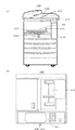
図1は、本発明の一実施例を示す画像処理装置の外観を示す図である。なお、図1(A)は画像処理装置を正面から見た図に対応する。また、図1(B)は画像処理装置を上面から見た図に対応する。   FIG. 1 is a diagram showing the appearance of an image processing apparatus according to an embodiment of the present invention. Note that FIG. 1A corresponds to a view of the image processing apparatus as viewed from the front. FIG. 1B corresponds to a view of the image processing apparatus as viewed from above.

図1に示すように、画像処理装置100は、操作部213、スキャナ215、胴内フィニッシャー(胴内排紙部)103、プリンタ216などから構成される。画像処理装置100は、コピー、プリント、FAX、スキャンなどの機能を持つ。   As shown in FIG. 1, the image processing apparatus 100 includes an operation unit 213, a scanner 215, an in-body finisher (in-body discharge unit) 103, a printer 216, and the like. The image processing apparatus 100 has functions such as copy, print, FAX, and scan.

画像処理装置100は、通常電力モード(第1電力状態)、通常電力モードよりも消費電力が小さい省電力モード2(第2電力状態)、省電力モード2よりも消費電力が小さい省電力モード1(第3電力状態)のいずれかに切り替えて動作可能である。   The image processing apparatus 100 includes a normal power mode (first power state), a power saving mode 2 (second power state) that consumes less power than the normal power mode, and a power saving mode 1 that consumes less power than the power saving mode 2. It is possible to operate by switching to any one of (third power state).

画像処理装置100は、人感センサ230と人感センサ231とを有する。
人感センサ230は、省電力モード1で動作するセンサ(第1検知部)であり、図2(A)及び(B)の111に示すような検知範囲を有し、広範囲に物体を検知する。
人感センサ231は、省電力モード2で動作するセンサ(第2検知部)であり、図2(A)及び(B)の112に示すような検知範囲を有し、人感センサ230より狭い範囲で物体を検知する。
The image processing apparatus 100 includes a human sensor 230 and a human sensor 231.
The human sensor 230 is a sensor (first detection unit) that operates in the power saving mode 1, has a detection range as indicated by 111 in FIGS. 2A and 2B, and detects an object in a wide range. .
The human sensor 231 is a sensor (second detector) that operates in the power saving mode 2, has a detection range as indicated by 112 in FIGS. 2A and 2B, and is narrower than the human sensor 230. Detect objects in range.

人感センサ230,人感センサ231が検知する物体は、静止体であっても移動体であってもよい。本実施例では、人感センサ230,人感センサ231が検知する物体を人体として説明するが、人感センサ230,人感センサ231が検知する物体は人体に限定されるものではない。本実施例では、人感センサ230,人感センサ231は、人体等の物体が近づいてきたことを検知可能である。   The object detected by the human sensor 230 and the human sensor 231 may be a stationary body or a moving body. In this embodiment, the object detected by the human sensor 230 and the human sensor 231 is described as a human body, but the object detected by the human sensor 230 and the human sensor 231 is not limited to the human body. In the present embodiment, the human sensor 230 and the human sensor 231 can detect that an object such as a human body is approaching.

また、画像処理装置100は、排紙センサ232と、排紙センサ233とを有する。排紙センサ232は、出力した紙が胴内フィニッシャー103にあることを検知するセンサ(排紙検知部)である。排紙センサ233は、出力した紙をユーザが取る動作(ユーザの手)を検知するセンサ(第3検知部)であり、図2(A)の110に示すような検知範囲を有する。   In addition, the image processing apparatus 100 includes a paper discharge sensor 232 and a paper discharge sensor 233. The paper discharge sensor 232 is a sensor (paper discharge detection unit) that detects that the output paper is in the in-body finisher 103. The paper discharge sensor 233 is a sensor (third detection unit) that detects an operation (a user's hand) of taking the output paper, and has a detection range as indicated by 110 in FIG.

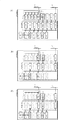
図2は、人感センサ231、230、排紙センサ233の検知範囲の一例を示す図である。なお、図2(A)は画像処理装置100を正面から見た場合の検知範囲を示す。また、図2(B)は画像処理装置100を上面から見た場合の検知範囲を示す。   FIG. 2 is a diagram illustrating an example of detection ranges of the human sensors 231 and 230 and the paper discharge sensor 233. 2A shows a detection range when the image processing apparatus 100 is viewed from the front. FIG. 2B shows a detection range when the image processing apparatus 100 is viewed from above.

人感センサ230、231、排紙センサ233は、焦電センサや反射センサなど離れた場所にある物体を検知するようなセンサを用いる。例えば、人感センサ230に焦電センサ、人感センサ231に反射センサ、排紙センサ233に反射センサを用いる。なお、焦電センサはパッシブ型の人感センサで、人体等の温度を持つものから自然に放射されている赤外線による温度変化を検知することで人体の接近を検出するものである。焦電センサは、消費電力が小さく、検知領域は比較的広いのが特徴である。また、反射センサはアクティブ型の人感センサで、自ら赤外線を発光して人体を検出するものである。反射センサは、焦電センサと比較して消費電力が大きく、検知領域は比較的狭いのが特徴である。なお、各センサ230〜233に用いられる赤外線センサは、赤外線センサをN×Nアレイ状に並べたセンサアレイを用いてもよい。   As the human sensors 230 and 231 and the paper discharge sensor 233, sensors such as a pyroelectric sensor and a reflection sensor that detect an object in a remote place are used. For example, a pyroelectric sensor is used as the human sensor 230, a reflective sensor is used as the human sensor 231, and a reflective sensor is used as the paper discharge sensor 233. The pyroelectric sensor is a passive human sensor that detects the approach of the human body by detecting a temperature change caused by infrared rays that are naturally emitted from a human body or the like. The pyroelectric sensor is characterized by low power consumption and a relatively wide detection area. The reflection sensor is an active human sensor that detects the human body by emitting infrared light. The reflection sensor is characterized in that it consumes more power than the pyroelectric sensor and the detection area is relatively narrow. In addition, the infrared sensor used for each sensor 230-233 may use the sensor array which arranged the infrared sensor in the NxN array form.

排紙センサ232は、紙が置いてある場合に倒れるようなセンサを用いても良いし、焦電センサや反射センサなどの赤外線センサを用いても良い。また、本実施例では、胴内フィニッシャー103に絞った説明をしているが、機外排紙などであっても良い。
なお、排紙センサ233は、実施例3、4の画像処理装置に備えられているものであり、実施例1、2の画像処理装置では、備えられていない。
The paper discharge sensor 232 may be a sensor that falls when paper is placed, or may be an infrared sensor such as a pyroelectric sensor or a reflection sensor. In this embodiment, the description is focused on the in-body finisher 103, but it may be discharged outside the machine.
The paper discharge sensor 233 is provided in the image processing apparatuses according to the third and fourth embodiments, and is not provided in the image processing apparatuses according to the first and second embodiments.

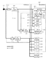
図3は、実施例1における画像処理装置100のハードウェア構成の一例を示すブロック図である。
図3(A)において、226は情報処理装置(コントローラ部)であり、画像処理装置100を制御する。情報処理装置226は、LANコントローラ212を介してLAN224に接続され、FAX225を介して電話回線223に接続される。以下、情報処理装置226の内部構成について説明する。
FIG. 3 is a block diagram illustrating an example of a hardware configuration of the image processing apparatus 100 according to the first embodiment.
In FIG. 3A, reference numeral 226 denotes an information processing apparatus (controller unit) that controls the image processing apparatus 100. The information processing apparatus 226 is connected to the LAN 224 via the LAN controller 212 and connected to the telephone line 223 via the FAX 225. Hereinafter, the internal configuration of the information processing apparatus 226 will be described.

CPU204は、情報処理装置226の装置全体を制御するソフトウェアプログラムを実行する。RAM206は、CPU204が装置を制御する際の一時的なデータの格納などに使用される。ROM205は、CPU204が実行するプログラム(装置の起動プログラム等)や各種設定値等が格納されている。ストレージ207は、HDD(Hard Disk Drive)やSSD(Solid State Drive)であり、様々なデータ格納に使用される。   The CPU 204 executes a software program that controls the entire information processing apparatus 226. The RAM 206 is used for temporarily storing data when the CPU 204 controls the apparatus. The ROM 205 stores programs executed by the CPU 204 (device startup programs and the like), various setting values, and the like. The storage 207 is an HDD (Hard Disk Drive) or an SSD (Solid State Drive), and is used for storing various data.

操作部213は、操作用液晶パネルや電源キー214を含むハードキーを備え、ユーザから入力される指示を受け付ける。操作部I/F209は、CPU204から操作部213の制御を行うためのインタフェースである。   The operation unit 213 includes hard keys including an operation liquid crystal panel and a power key 214, and receives instructions input from the user. An operation unit I / F 209 is an interface for controlling the operation unit 213 from the CPU 204.

スキャナ215は、原稿台またはADF(Auto Document Feeder)に設置された原稿の画像を読み取り、画像を生成する。スキャナI/F210は、CPU204からスキャナ215の制御を行うためのインタフェースである。プリンタ216は、画像データに基づく画像を紙に印刷する。プリンタI/F211は、CPU204からプリンタの制御を行うためのインタフェースである。   The scanner 215 reads an image of a document placed on a document table or an ADF (Auto Document Feeder) and generates an image. A scanner I / F 210 is an interface for controlling the scanner 215 from the CPU 204. The printer 216 prints an image based on the image data on paper. A printer I / F 211 is an interface for controlling the printer from the CPU 204.

FAX225は、モデム218、CPU219、RAM221、ROM220、受信検知部222で構成される。画像処理装置100は、FAX225を介して、電話回線の外部装置とのデータ通信制御を行う。   The FAX 225 includes a modem 218, a CPU 219, a RAM 221, a ROM 220, and a reception detection unit 222. The image processing apparatus 100 performs data communication control with an external apparatus on the telephone line via the FAX 225.

モデム218は、FAX225の送受信のための変調を行う。CPU219は、FAX I/F208を介して情報処理装置226と連携してFAX225の送受信の制御を行う。   The modem 218 performs modulation for transmission / reception of the FAX 225. The CPU 219 controls transmission / reception of the FAX 225 in cooperation with the information processing apparatus 226 via the FAX I / F 208.

RAM221は、CPU219が装置を制御する際に一時的なデータ格納などに使用する。ROM220は、FAX225装置の起動プログラムや各種設定値等が格納されている。FAX225のCPU219、ROM220、及びRAM221を設ける代わりに、これら219〜221の機能を、情報処理装置226が有する構成でもよい。
FAX I/F208は、CPU204からFAX225の制御を行うためのインタフェースである。
The RAM 221 is used for temporary data storage when the CPU 219 controls the apparatus. The ROM 220 stores a startup program for the FAX 225 device, various setting values, and the like. Instead of providing the CPU 219, the ROM 220, and the RAM 221 of the FAX 225, the information processing apparatus 226 may have the functions of these 219 to 221.
A FAX I / F 208 is an interface for controlling the FAX 225 from the CPU 204.

電源制御部203は、電源部202から必要な箇所に電源を供給する制御(電力制御)を行う。第一の人感センサ230は、図1(A)で示す231に該当し、広範囲に人が近づいてきたことを検知するセンサである。第二の人感センサ231は、図1(A)で示す230に該当し、第一の人感センサ230より狭い範囲で人が近づいてきたことを検知するセンサである。排紙センサ232は図1(A)で示す232に該当し、紙が出力されて胴内フィニッシャーにある状態を検知するセンサである。   The power supply control unit 203 performs control (power control) for supplying power from the power supply unit 202 to a necessary location. The first human sensor 230 corresponds to 231 shown in FIG. 1A, and is a sensor that detects that a person has approached a wide range. The second human sensor 231 corresponds to 230 shown in FIG. 1A and is a sensor that detects that a person has approached in a narrower range than the first human sensor 230. The paper discharge sensor 232 corresponds to 232 shown in FIG. 1A, and is a sensor that detects a state in which paper is output and is in the in-cylinder finisher.

「通常電力モード」では、図3(A)に示す全てのブロックに電源が供給されている。この際に、必要な機能にのみ給電するような形態を取っても良いが、ここでは明記しない。   In the “normal power mode”, power is supplied to all the blocks shown in FIG. At this time, it may take a form in which power is supplied only to necessary functions, but it is not specified here.

「省電力モード1」では、図3(B)に示すように、一部のブロックに電源が給電されている。まず、電源201から電源部202に電源が供給される。電源部202から供給されるブロックは、電源制御部203、RAM206、第一の人感センサ230、FAX I/F208、受信検知部222、電源キー214、操作部IF209、LANコントローラ212、LAN I/F217であり、グレー表示されたブロック(CPU204、ROM205、ストレージ207、第2の人感センサ231、排紙センサ232、スキャナI/F210、プリンタI/F211、スキャナ215、プリンタ216、およびFAX225の一部(モデム218、CPU219、ROM220、RAM222))へは給電されない。なお、RAM206は、必要に応じて電源を供給し、全てに供給する必要はない。また、操作部213への給電は、電源キー214のみを記載したが、ユーザのタッチを認識する機能など他の電力状態への移行条件に応じて電源を給電しても良い。   In “power saving mode 1”, as shown in FIG. 3B, power is supplied to some blocks. First, power is supplied from the power supply 201 to the power supply unit 202. The blocks supplied from the power supply unit 202 include a power supply control unit 203, a RAM 206, a first human sensor 230, a FAX I / F 208, a reception detection unit 222, a power key 214, an operation unit IF 209, a LAN controller 212, a LAN I / O. F 217, one of the gray blocks (CPU 204, ROM 205, storage 207, second human sensor 231, paper discharge sensor 232, scanner I / F 210, printer I / F 211, scanner 215, printer 216, and FAX 225 No power is supplied to the units (modem 218, CPU 219, ROM 220, RAM 222). The RAM 206 supplies power as necessary, and does not need to be supplied to all. In addition, although only the power key 214 is described for power supply to the operation unit 213, the power supply may be supplied according to a transition condition to another power state such as a function of recognizing a user's touch.

ここで、「省電力モード2」や「通常電力モード」への移行条件について説明する。
まず、「省電力モード1」から「省電力モード2」への移行について説明する。「省電力モード1」において、第一の人感センサ230が、人が近づいてきたことを検知した場合には、電源制御部203へ省電力モード2への移行命令を送信し、図3(C)に示すようなブロックに給電を行う「省電力モード2」へ移行する。「省電力モード2」では、「省電力モード1」での給電ブロックに加え、第二の人感センサ231と排紙センサ232に給電を行う。
Here, the transition conditions to “power saving mode 2” and “normal power mode” will be described.
First, the transition from “power saving mode 1” to “power saving mode 2” will be described. In the “power saving mode 1”, when the first human sensor 230 detects that a person is approaching, a command to shift to the power saving mode 2 is transmitted to the power control unit 203, and FIG. Shift to “power saving mode 2” in which power is supplied to the block as shown in FIG. In the “power saving mode 2”, power is supplied to the second human sensor 231 and the paper discharge sensor 232 in addition to the power supply block in the “power saving mode 1”.

次に、「通常電力モード」への移行条件について説明する。「省電力モード1」又は「省電力モード2」において、受信検知部222がFAX受信を検知した場合には、電源制御部203へFAX I/Fを経由して「通常電力モード」への移行命令を送信し、「通常電力モード」へ移行する。また、同様に、LAN I/F217より印刷ジョブなど「通常電力モード」への移行が必要なジョブを、LANコントローラ212が受信した場合には、電源制御部203へ「通常電力モード」への移行命令を送信し、「通常電力モード」へ移行する。また、同様に、ユーザから電源キー214が押されたと検知した場合に、操作部I/F209を経由して電源制御部203へ「通常電力モード」への移行命令を送信し、「通常電力モード」へ移行する。操作部213は、電源キー214のみ記載しているが、ユーザのタッチを認識して割り込みを電源制御部203に送信する構成を取っても良い。   Next, the conditions for shifting to the “normal power mode” will be described. In the “power saving mode 1” or “power saving mode 2”, when the reception detection unit 222 detects FAX reception, the power control unit 203 shifts to the “normal power mode” via the FAX I / F. Send the command and go to “normal power mode”. Similarly, when the LAN controller 212 receives a job that needs to be shifted to the “normal power mode” such as a print job from the LAN I / F 217, the power controller 203 shifts to the “normal power mode”. Send the command and go to “normal power mode”. Similarly, when it is detected that the user presses the power key 214, a command to shift to the “normal power mode” is transmitted to the power control unit 203 via the operation unit I / F 209, and the “normal power mode” is transmitted. ”. Although only the power key 214 is described in the operation unit 213, a configuration in which an interrupt is transmitted to the power control unit 203 upon recognition of the user's touch may be adopted.

次に、「省電力モード2」と「省電力モード1」の差分について説明する。
「省電力モード2」において、第一の人感センサ230により人が近くにいることを検知している間は、「省電力モード2」を継続する。第一の人感センサ230が人を検知出来ず、人が離れたと判定された場合には、電源制御部203へ「省電力モード1」への移行命令を送信し、「省電力モード1」へ移行する。
Next, the difference between “power saving mode 2” and “power saving mode 1” will be described.
In the “power saving mode 2”, the “power saving mode 2” is continued while the first human sensor 230 detects that a person is nearby. If the first human sensor 230 cannot detect a person and it is determined that the person has left, a command to shift to “power saving mode 1” is transmitted to the power supply control unit 203, and “power saving mode 1” is transmitted. Migrate to

また、「省電力モード2」において、第二の人感センサ231により人が近づいてきたことを検知した場合には、電源制御部203へ「通常電力モード」への移行命令を送信し、「通常電力モード」へ移行する。なお、第二の人感センサ231により人が近づいてきたことを検知した場合であっても、排紙センサ232により胴内フィニッシャー103に紙の存在を検知した場合には、第二の人感センサ231での人の検知に応じた通常電力モードへの移行を一時的に制限する。   In addition, in the “power saving mode 2”, when the second human sensor 231 detects that a person is approaching, a command to shift to the “normal power mode” is transmitted to the power control unit 203, and “ Transition to “normal power mode”. Even when the second human sensor 231 detects that a person is approaching, if the paper discharge sensor 232 detects the presence of paper in the in-body finisher 103, the second human sensor. The transition to the normal power mode according to the detection of the person by the sensor 231 is temporarily restricted.

以下、図4A、図4Bを用いて、実施例1における、センサを用いた電力モード移行に関して、詳細に説明する。
図4Aは、実施例1における画像処理装置100の給電構成の一例を示すブロック図であり、図3と同一のものには同一の符号を付してある。
電源201より入力された電源は、SW310、SW312に接続される。SW310は、電源制御部203またはユーザが手動でオンすることが出来るシーソーSWやボタンSWなどにより、オンされる。
Hereinafter, the power mode transition using the sensor in the first embodiment will be described in detail with reference to FIGS. 4A and 4B.
4A is a block diagram illustrating an example of a power supply configuration of the image processing apparatus 100 according to the first embodiment. The same components as those in FIG. 3 are denoted by the same reference numerals.
A power source input from the power source 201 is connected to SW 310 and SW 312. The SW 310 is turned on by the power control unit 203 or a seesaw SW or a button SW that can be turned on manually by the user.

SW310がオンされると、電源201より供給される電力が、第一電源部300に給電される。第一電源部300は、省電力モード1、省電力モード2、及び通常電力モードで動作するブロックに電力供給する。   When the SW 310 is turned on, the power supplied from the power source 201 is supplied to the first power source unit 300. The first power supply unit 300 supplies power to blocks operating in the power saving mode 1, the power saving mode 2, and the normal power mode.

SW311がオンされた場合、第一電源部300から供給される電力が、第二電源部301に給電される。第二電源部301は、省電力モード2、及び通常電力モードで動作するブロックに電力供給する。なお、第二電源部301は、電源201より直接給電されても良いし、第一電源部300から給電されても良い。   When the SW 311 is turned on, the power supplied from the first power supply unit 300 is supplied to the second power supply unit 301. The second power supply unit 301 supplies power to the blocks operating in the power saving mode 2 and the normal power mode. The second power supply unit 301 may be directly supplied with power from the power supply 201 or may be supplied with power from the first power supply unit 300.

SW312がオンされた場合、電源201より供給される電力が、第三電源部302に給電される。第三電源部302は、通常電力モードで動作するブロックに電力供給する。なお、第三電源部302は、電源201より直接給電されても良いし、第一電源部300から給電されても良い。   When the SW 312 is turned on, the power supplied from the power supply 201 is supplied to the third power supply unit 302. The third power supply unit 302 supplies power to the block that operates in the normal power mode. The third power supply unit 302 may be directly supplied with power from the power supply 201 or may be supplied with power from the first power supply unit 300.

SW311、SW312は、リレーやFETなど、給電状態を切り替えることの出来るデバイスであれば良い。
なお、SW310がオンされた場合には、自動で電源制御部203からSW311へオン命令512、SW312へオン命令513を送信して通常電力モードへ移行しても良い。
SW311 and SW312 may be devices that can switch the power supply state, such as relays and FETs.
When the SW 310 is turned on, the power supply control unit 203 may automatically transmit an ON command 512 to the SW 311 and an ON command 513 to the SW 312 to shift to the normal power mode.

省電力モード1から省電力モード2へ移行する条件は、第一の人感センサ230が人を検知した場合である。第一の人感センサ230が人を検知した時、電源制御部203へSW311をオンにする依頼信号511を送信する。電源制御部203が依頼信号511を受信すると、SW311へオン命令512が送信され、第二電源部301へ給電される。   The condition for shifting from the power saving mode 1 to the power saving mode 2 is when the first human sensor 230 detects a person. When the first human sensor 230 detects a person, a request signal 511 for turning on the SW 311 is transmitted to the power supply control unit 203. When the power supply control unit 203 receives the request signal 511, an ON command 512 is transmitted to the SW 311 and power is supplied to the second power supply unit 301.

次に、通常電力モードへの移行条件について説明する。
ロジック313は、通常電力モードへ移行する必要のある依頼信号(501〜504、511)を一つでも受信した場合に、電源制御部203へ移行依頼信号500を送信する。以下、依頼信号を夫々説明する。
Next, conditions for shifting to the normal power mode will be described.
When the logic 313 receives at least one request signal (501 to 504, 511) that needs to shift to the normal power mode, the logic 313 transmits the shift request signal 500 to the power supply control unit 203. Hereinafter, each of the request signals will be described.

LANコントローラ212が印刷ジョブなど通常電力モードへ移行する必要のある命令を受信した場合にロジック313に依頼命令501を送信する。なお、LANコントローラ212は、LAN I/F217を介して命令を受信するが、図4AではLAN I/F217の記載を省略している。   When the LAN controller 212 receives a command such as a print job that needs to shift to the normal power mode, it sends a request command 501 to the logic 313. The LAN controller 212 receives a command via the LAN I / F 217, but the LAN I / F 217 is not shown in FIG. 4A.

また、受信検知部222がFAXの受信を検知した場合に、ロジック313に依頼命令502を送信する。なお、依頼命令502は、FAX I/F208を介してロジック313に送信されるが、図4AではFAX I/F208の記載を省略している。   Further, when the reception detection unit 222 detects reception of a FAX, a request command 502 is transmitted to the logic 313. The request command 502 is transmitted to the logic 313 via the FAX I / F 208, but the description of the FAX I / F 208 is omitted in FIG. 4A.

また、電源キー214がユーザに押された場合に、ロジック313に依頼命令503を送信する。なお、依頼命令503は、操作部I/F209を介してロジック313に送信されるが、図4Aでは操作部I/F209の記載を省略している。   Further, when the power key 214 is pressed by the user, a request command 503 is transmitted to the logic 313. The request command 503 is transmitted to the logic 313 via the operation unit I / F 209, but the description of the operation unit I / F 209 is omitted in FIG. 4A.

また、第二電源部301で供給される排紙センサ232と第二の人感センサ231の検知状態により、通常電力モードへ移行すると判定された場合には、ロジック313に依頼命令504を送信する。詳細は後ほど図4Bを用いて説明する。   If it is determined that the normal power mode is to be entered based on the detection states of the paper discharge sensor 232 and the second human sensor 231 supplied by the second power supply unit 301, a request command 504 is transmitted to the logic 313. . Details will be described later with reference to FIG. 4B.

ロジック313より移行依頼信号500を電源制御部203が受信した場合には、電源制御部203は、SW312へオン命令513を送信し、第三電源部302が給電される。第三電源部302は、通常電力モードで使用されるブロックに給電する。なお、省電力モード1の状態で移行依頼信号500を受信した場合、電源制御部203は、さらにSW311へのオン命令512も送信するようにしてもよい。電源201から給電される電源は、第一電源部300、第二電源部301、第三電源部302の三種類に分けて供給される。
なお、図4Aでは、スキャナI/F210、プリンタI/F211の記載を省略している。
When the power supply control unit 203 receives the transition request signal 500 from the logic 313, the power supply control unit 203 transmits an ON command 513 to the SW 312 and the third power supply unit 302 is powered. The third power supply unit 302 supplies power to the block used in the normal power mode. Note that when the shift request signal 500 is received in the state of the power saving mode 1, the power supply control unit 203 may further transmit an on command 512 to the SW 311. The power supplied from the power source 201 is divided into three types, ie, a first power source unit 300, a second power source unit 301, and a third power source unit 302.
In FIG. 4A, descriptions of the scanner I / F 210 and the printer I / F 211 are omitted.

図4Bは、実施例1における、排紙センサ232と第二の人感センサ231についての詳細なブロック図である。
排紙センサ232内にある検知部400は、胴内フィニッシャー103内の紙の有無を示す信号518を状態判定部401へ出力する。同様に、第二の人感センサ231は、人の有無を示す信号515を状態判定部401へ出力する。
FIG. 4B is a detailed block diagram of the paper discharge sensor 232 and the second human sensor 231 in the first embodiment.
The detection unit 400 in the paper discharge sensor 232 outputs a signal 518 indicating the presence / absence of paper in the in-body finisher 103 to the state determination unit 401. Similarly, the second human sensor 231 outputs a signal 515 indicating the presence or absence of a person to the state determination unit 401.

状態判定部401は、検知部400の紙検知状態を判定し、省電力モード2において、検知部400が紙を検知している場合には、第二の人感センサ231が人を検知した場合でも、通常電力モードへ移行を遅らせるように制御する。以下、具体的に説明する。   The state determination unit 401 determines the paper detection state of the detection unit 400. When the detection unit 400 detects paper in the power saving mode 2, the second human sensor 231 detects a person. However, control is performed to delay the transition to the normal power mode. This will be specifically described below.

状態判定部401は、信号518がLowの場合(検知部400が紙を検知していない場合)、第二の人感センサ231から入力される信号515を、信号519として、出力判定部403へ出力する。出力判定部403は、状態判定部401からの入力信号519がHigh(第二の人感センサ231が人を検知している)になると、依頼命令504をロジック313に送信する。これにより、電源制御部203からSW312にオン命令513が送信され、第三電源部302が給電され、画像処理装置100が通常電力モードへ移行することになる。   When the signal 518 is Low (when the detection unit 400 has not detected paper), the state determination unit 401 uses the signal 515 input from the second human sensor 231 as the signal 519 to the output determination unit 403. Output. The output determination unit 403 transmits a request command 504 to the logic 313 when the input signal 519 from the state determination unit 401 becomes High (the second human sensor 231 detects a person). As a result, an ON command 513 is transmitted from the power supply control unit 203 to the SW 312, the third power supply unit 302 is supplied with power, and the image processing apparatus 100 shifts to the normal power mode.

一方、信号518がHighの場合(検知部400が紙を検知している場合)、状態判定部401は、第二の人感センサ231から入力される信号515を、信号520として、遅延回路402へ出力する。遅延回路402は、状態判定部401から入力される信号520を一定時間(例えば、人が第二の人感センサ231で検知されてから紙を取って第二の人感センサ231の検知範囲112(図2)から立ち去るのに十分な時間を想定した第1の時間)だけ遅延させて信号521として、出力判定部403へ出力する。出力判定部403は、遅延回路402からの入力信号521がHigh(第二の人感センサ231が人を検知している)になると、依頼命令504をロジック313に送信する。これにより、第二の人感センサ231が人を検知してから一定時間(第1の時間)遅れて、電源制御部203からSW312にオン命令513が送信され、第三電源部302が給電され、画像処理装置100が通常電力モードへ移行することになる。   On the other hand, when the signal 518 is High (when the detection unit 400 detects paper), the state determination unit 401 uses the signal 515 input from the second human sensor 231 as the signal 520, and the delay circuit 402. Output to. The delay circuit 402 receives the signal 520 input from the state determination unit 401 for a certain period of time (for example, after the person is detected by the second human sensor 231, the paper is taken and the detection range 112 of the second human sensor 231 is detected. A first time assuming a sufficient time to leave (FIG. 2)) is output as a signal 521 to the output determination unit 403. When the input signal 521 from the delay circuit 402 becomes High (the second human sensor 231 detects a person), the output determination unit 403 transmits a request command 504 to the logic 313. As a result, an on command 513 is transmitted from the power supply control unit 203 to the SW 312 after a certain time (first time) after the second human sensor 231 detects a person, and the third power supply unit 302 is powered. The image processing apparatus 100 shifts to the normal power mode.

なお、第三電源部302への給電を遅延させている間に(第1の時間が経過するまでの間に)、第二の人感センサ231からの信号515が人の検知状態(High)から非検知状態(Low)へ変化した場合、状態判定部401は、遅延回路402からの遅延信号521を無効にする無効信号522をHigh状態にして出力判定部403へ送信する。出力判定部403は、無効信号522がHigh状態の場合、遅延信号521がHigh状態となっても、依頼命令504を出力しない。なお、状態判定部401は、一定時間(少なくとも第1の時間)、無効信号522をHigh状態に保持する。即ち、上述の遅延された信号による通常電力モードへの移行は行われない。なお、状態判定部401が無効信号522をHigh状態に保持している間でも、第一の人感センサ230が人を検知しなくなると、画像処理装置100は、省電力モード1に移行する。   Note that while the power supply to the third power supply unit 302 is delayed (until the first time elapses), the signal 515 from the second human sensor 231 is a human detection state (High). When the state is changed from non-detection state (Low), the state determination unit 401 sets the invalid signal 522 for invalidating the delay signal 521 from the delay circuit 402 to a high state and transmits the invalid signal 522 to the output determination unit 403. When the invalid signal 522 is in the high state, the output determination unit 403 does not output the request instruction 504 even if the delay signal 521 is in the high state. Note that the state determination unit 401 holds the invalid signal 522 in the High state for a certain time (at least the first time). That is, the transition to the normal power mode by the delayed signal is not performed. Even when the state determination unit 401 holds the invalid signal 522 in the high state, the image processing apparatus 100 shifts to the power saving mode 1 when the first human sensor 230 no longer detects a person.

また、第三電源部302への給電を遅延させている間に(第1定時間が経過するまでの間に)、第二の人感センサ231からの信号515は検知状態(High)であるが、検知部400からの信号518が検知状態(High)から非検知状態(Low)へ変化した場合、状態判定部401は、無効信号522を出力判定部403へ送信する。状態判定部401は、一定時間(少なくとも第1の時間)、無効信号522をHigh状態に保持する。また、状態判定部401は、一定時間(例えば、紙を取った人が第二の人感センサ231の検知範囲112(図2)から立ち去るのに十分な時間を想定した第2の時間)、信号519、信号520の出力を行わない。即ち、一定時間(第2の時間)、省電力モードが維持される。   Further, the signal 515 from the second human sensor 231 is in a detection state (High) while the power supply to the third power supply unit 302 is delayed (until the first fixed time elapses). However, when the signal 518 from the detection unit 400 changes from the detection state (High) to the non-detection state (Low), the state determination unit 401 transmits an invalid signal 522 to the output determination unit 403. The state determination unit 401 holds the invalid signal 522 in the High state for a certain time (at least the first time). In addition, the state determination unit 401 has a fixed time (for example, a second time assuming a time sufficient for the person who took the paper to leave the detection range 112 (FIG. 2) of the second human sensor 231). The signals 519 and 520 are not output. That is, the power saving mode is maintained for a certain time (second time).

また、状態判定部401は、通常電力モードにおいて、信号518がHighの状態(検知部400が紙を検知している状態)が一定時間(例えば、印刷ジョブを投入してから紙を取りに来るまでに十分な時間を想定した第3の時間)以上継続した場合、状態判定部401内のレジスタ401aに排紙フラグとして「1」を記憶する。そして、省電力モードにおいて、状態判定部401は、排紙フラグが「1」の場合、信号518に関係なく、第二の人感センサ231から入力される信号515を、信号519として出力判定部403へ出力する。このように、胴内フィニッシャー103に紙が一定時間(第3の時間)以上放置されていた場合には、検知部400による紙の検知状態に関係なく、第二の人感センサ231が人を検知した場合には、通常電力モードへ移行することになる。
なお、上述した状態判定部401、遅延回路402、出力判定部403は第二の人感センサ231内に持っても良い。
In addition, the state determination unit 401 is in the normal power mode, and the state where the signal 518 is High (the state in which the detection unit 400 detects paper) is for a certain period of time (for example, after a print job is input, picks up paper). In the case where the time has continued for a sufficient time until the third time), “1” is stored in the register 401a in the state determination unit 401 as a paper discharge flag. In the power saving mode, the state determination unit 401 outputs the signal 515 input from the second human sensor 231 as the signal 519 regardless of the signal 518 when the paper discharge flag is “1”. Output to 403. As described above, when the paper is left on the in-cylinder finisher 103 for a certain time (third time) or longer, the second human sensor 231 detects the person regardless of the paper detection state by the detection unit 400. If it is detected, the normal power mode is entered.
The state determination unit 401, the delay circuit 402, and the output determination unit 403 described above may be included in the second human sensor 231.

以下、図5のフローチャートを参照して、上述した構成により実現される画像処理装置100のセンサ電源制御について説明する。
なお、図5のフローチャートでは、上述したLANコントローラ212のジョブ受信、受信検知部222のFAX受信検知、電源キー214の押下等の移行条件に応じた通常電力モードへの移行は省略するが、図5に示す処理の途中で、上記移行条件に応じた移行命令を電源制御部203が受信した場合には通常電力モードへ移行することは言うまでもない。
Hereinafter, sensor power control of the image processing apparatus 100 realized by the above-described configuration will be described with reference to the flowchart of FIG.
In the flowchart of FIG. 5, the transition to the normal power mode according to the transition conditions such as job reception of the LAN controller 212, FAX reception detection of the reception detection unit 222, and pressing of the power key 214 is omitted. Needless to say, when the power supply control unit 203 receives a transition command corresponding to the transition condition during the process shown in FIG.

図5は、実施例1における画像処理装置100のセンサ電源制御の一例を示すフローチャートである。
画像処理装置100は、通常電力モードから省電力モードへ移行しない場合(S11でNoの場合)、即ち、通常電力モードの場合、S12〜S15に示す処理を実行する。
S12では、排紙センサ232の状態判定部401が、検知部400からの入力信号518に基づいて、胴内フィニッシャー103上に排紙された用紙が有るか無いかを判定する。
FIG. 5 is a flowchart illustrating an example of sensor power control of the image processing apparatus 100 according to the first embodiment.
When the image processing apparatus 100 does not shift from the normal power mode to the power saving mode (No in S11), that is, in the normal power mode, the image processing apparatus 100 executes the processes shown in S12 to S15.
In step S <b> 12, the state determination unit 401 of the paper discharge sensor 232 determines whether or not there is a discharged paper on the in-body finisher 103 based on the input signal 518 from the detection unit 400.

そして、用紙が有ると判定した場合(S12でYesの場合)、状態判定部401は、S13に処理を進める。
S13では、状態判定部401は、用紙有りの状態が一定時間(第3の時間)経過したかを判定する。
If it is determined that there is a sheet (Yes in S12), the state determination unit 401 advances the process to S13.
In step S <b> 13, the state determination unit 401 determines whether a certain time (third time) has elapsed in the state where the sheet is present.

そして、用紙有りの状態が一定時間(第3の時間)経過したと判定した場合(S13でYesの場合)、状態判定部401は、状態判定部401内のレジスタ401aに排紙フラグとして「1」を記憶する(S14)。これは、印刷出力した用紙が置いたままになっているかを判定している。一定時間(第3の時間)経過している場合には、置いたままになっているケースが考えられるため、次に近づいてきたユーザが画像処理装置100を使用する可能性が高い。ここで指定している一定時間とは、印刷ジョブを投入してから紙を取りに来るまでの時間を想定して、設定しておく。なお、省電力モードへ移行しない場合には、排紙フラグは使用しない。   If it is determined that a certain time (third time) has passed since the sheet is present (Yes in S13), the state determination unit 401 sets “1” as a paper discharge flag in the register 401a in the state determination unit 401. Is stored (S14). This determines whether the printed paper is left on the paper. When a certain time (third time) has elapsed, it is possible that the user has left the device for a certain period of time. Therefore, the user who approaches next is likely to use the image processing apparatus 100. The fixed time specified here is set assuming the time from when a print job is input until paper is picked up. Note that the paper discharge flag is not used when the mode does not shift to the power saving mode.

一方、用紙有りの状態が一定時間(第3の時間)経過していないと判定した場合(S13でNoの場合)、状態判定部401は、状態判定部401内のレジスタ401aに排紙フラグとして「0」を記憶する(S15)。   On the other hand, when it is determined that the state where the sheet is present does not elapse for a certain period of time (third time) (No in S13), the state determination unit 401 uses the register 401a in the state determination unit 401 as a discharge flag. “0” is stored (S15).

また、上記S12において、胴内フィニッシャー103上に排紙された用紙が無いと判定した場合(S12でNoの場合)、状態判定部401は、状態判定部401内のレジスタに排紙フラグとして「0」を記憶する(S15)。   If it is determined in S12 that there is no discharged sheet on the in-cylinder finisher 103 (No in S12), the state determination unit 401 displays “ “0” is stored (S15).

そして、上記S14又はS15の後に、省電力モードへ移行しない場合(S11でNoの場合)、状態判定部401は、再度、S12〜S15に示す処理を実行する。
また、通常電力モードから省電力モードへ移行した場合(S11でYesの場合)、即ち、省電力モードの場合、画像処理装置100は、S16以降に示す処理を実行する。
And after the said S14 or S15, when not changing to a power saving mode (in the case of No in S11), the state determination part 401 performs the process shown to S12-S15 again.
Further, in the case of shifting from the normal power mode to the power saving mode (Yes in S11), that is, in the power saving mode, the image processing apparatus 100 executes the processes after S16.

第一の人感センサ230が人を検知していない場合(S16でNoの場合)、画像処理装置100は、第二電源部301の電源の供給をOFFにし(S17)、S16に処理を戻す。上記S17では、電源制御部203が、電源部202へ省電力モード1への移行命令を発行し(SW311へオフ命令を出力し)、第二電源部301の電源の供給をOFFにする。第二電源部301への給電が停止されると、第二の人感センサ231、排紙センサ232への給電が停止される。   When the first human sensor 230 does not detect a person (No in S16), the image processing apparatus 100 turns off the power supply of the second power supply unit 301 (S17), and returns the process to S16. . In S <b> 17, the power supply control unit 203 issues a command to shift to the power saving mode 1 to the power supply unit 202 (outputs an off command to the SW 311), and turns off the power supply of the second power supply unit 301. When power supply to the second power supply unit 301 is stopped, power supply to the second human sensor 231 and the paper discharge sensor 232 is stopped.

一方、第一の人感センサ230が人を検知した場合(S16でYesの場合)、画像処理装置100は、第二電源部301への給電をONする(S18)。上記S18では、電源制御部203が、電源部202へ省電力モード2への移行命令を発行し(SW311へオン命令を出力し)、第二電源部301への給電をONする。第二電源部301への給電が開始されると、第二の人感センサ231、排紙センサ232への給電が開始され、起動される。   On the other hand, when the first human sensor 230 detects a person (Yes in S16), the image processing apparatus 100 turns on the power supply to the second power supply unit 301 (S18). In S <b> 18, the power supply control unit 203 issues a command to shift to the power saving mode 2 to the power supply unit 202 (outputs an ON command to the SW 311), and turns on the power supply to the second power supply unit 301. When power supply to the second power supply unit 301 is started, power supply to the second human sensor 231 and the paper discharge sensor 232 is started and activated.

そして、第二の人感センサ231が人を検知していない場合(S19でNoの場合)、画像処理装置100は、上述の第一の人感センサ230の検知結果に基づく電源制御を実行する(S16〜S18)。   When the second human sensor 231 does not detect a person (No in S19), the image processing apparatus 100 executes power control based on the detection result of the first human sensor 230 described above. (S16-S18).

一方、第二の人感センサ231が人を検知している場合(S19でYesの場合)、画像処理装置100は、S20以降に示す処理を実行する。
排紙センサ232は、上述した排紙フラグが「1」であると判定した場合(S20でYesの場合)、依頼命令504を出力し、通常電力モードに移行させる(S23)。なお、排紙フラグが「1」の場合は、紙が一定時間(第3の時間)以上置いたままになっている場合であり、この場合、排紙センサ232は、検知したユーザは画像処理装置100を利用する可能性が高いと判断し、通常電力モードに移行させている。詳細には、状態判定部401が、第二の人感センサ231からの入力信号515を出力信号519として出力判定部403に出力し、出力判定部403が依頼命令504を出力する。これにより、電源制御部203が、電源部202へ通常電力モードへの移行命令を発行し(SW312へオン命令を出力し)、第三電源部302への給電をONする。これにより、通常電力モードへ移行する。
On the other hand, when the second human sensor 231 detects a person (Yes in S19), the image processing apparatus 100 executes the processes after S20.
When the paper discharge sensor 232 determines that the above-mentioned paper discharge flag is “1” (Yes in S20), the paper discharge sensor 232 outputs a request command 504 and shifts to the normal power mode (S23). When the paper discharge flag is “1”, the paper has been left for a certain period of time (third time) or longer. In this case, the paper discharge sensor 232 detects that the detected user has performed image processing. It is determined that there is a high possibility that the device 100 is used, and the mode is shifted to the normal power mode. Specifically, the state determination unit 401 outputs an input signal 515 from the second human sensor 231 as an output signal 519 to the output determination unit 403, and the output determination unit 403 outputs a request command 504. As a result, the power supply control unit 203 issues a command to shift to the normal power mode to the power supply unit 202 (outputs an ON command to the SW 312), and turns on the power supply to the third power supply unit 302. Thereby, it shifts to the normal power mode.

一方、排紙フラグが「1」でないと判定した場合(S20でNoの場合)、排紙センサ232は、検知部400が胴内フィニッシャー103上の用紙を検知した(排紙有り)か否(排紙無し)かに基づいて制御を行う。   On the other hand, if it is determined that the paper discharge flag is not “1” (No in S20), the paper discharge sensor 232 determines whether the detection unit 400 has detected the paper on the in-body finisher 103 (paper discharge is present) ( Control is performed based on whether there is no paper discharge.

排紙センサ232は、「排紙無し」と判定した場合(S21でNoの場合)、依頼命令504を出力し、通常電力モードに移行させる(S23)。詳細には、状態判定部401が、第二の人感センサ231からの入力信号515を出力信号519として出力判定部403に出力し、出力判定部403が依頼命令504を出力する。これにより、電源制御部203が第三電源部302への給電をONにし、通常電力モードへ移行する。   If the paper discharge sensor 232 determines that “no paper discharge” (No in S21), the paper discharge sensor 232 outputs a request command 504 to shift to the normal power mode (S23). Specifically, the state determination unit 401 outputs an input signal 515 from the second human sensor 231 as an output signal 519 to the output determination unit 403, and the output determination unit 403 outputs a request command 504. As a result, the power supply control unit 203 turns on the power supply to the third power supply unit 302 and shifts to the normal power mode.

一方、「排紙有り」と判定した場合(S21でYesの場合)、排紙センサ232は、通常電力モードへの移行を遅延させるための制御を行う。詳細には、状態判定部401が、第二の人感センサ231からの入力信号515を出力信号520として遅延回路402に出力する。さらに、状態判定部401は、「排紙有り」の状態で第二の人感センサ231が人を継続して検知している状態が一定時間(遅延回路402の遅延時間(第1の時間))経過したかを判定する(S22)。   On the other hand, when it is determined that “paper discharge is present” (Yes in S21), the paper discharge sensor 232 performs control for delaying the shift to the normal power mode. Specifically, the state determination unit 401 outputs the input signal 515 from the second human sensor 231 as the output signal 520 to the delay circuit 402. Further, the state determination unit 401 indicates that the state in which the second human sensor 231 continuously detects the person in the state of “paper discharged” is a fixed time (delay time (first time) of the delay circuit 402). ) It is determined whether it has elapsed (S22).

そして、まだ一定時間経過していないと判定した場合(S22でNoの場合)、排紙センサ232(詳細には状態判定部401)は、S24に処理を進める。そして、第二の人感センサ231が継続して人を検知しており、且つ、検知部400が胴内フィニッシャー103上の用紙を検知している(排紙有り)と判定した場合(S24でYes且つS25でNoの場合)、排紙センサ232(詳細には状態判定部401)は、S22に処理を戻し、一定時間経過の判定を続ける。   If it is determined that the predetermined time has not yet elapsed (No in S22), the paper discharge sensor 232 (specifically, the state determination unit 401) advances the process to S24. If the second human sensor 231 continues to detect a person and the detection unit 400 determines that the sheet on the in-cylinder finisher 103 is detected (discharged) (S24). In the case of Yes and No in S25), the paper discharge sensor 232 (specifically, the state determination unit 401) returns the process to S22 and continues to determine whether a certain time has elapsed.

そして、排紙ありの状態で第二の人感センサ231が人を継続して検知している状態が一定時間経過した場合(S22でYesの場合)、排紙センサ232は、依頼命令504を出力し、通常電力モードに移行させる(S23)。詳細には、遅延回路402から、High状態の出力信号521が出力判定部403に出力され、出力判定部403が依頼命令504を出力する。これにより、通常電力モードへ移行する。   When the second human sensor 231 continues to detect a person in a state where there is paper discharge for a certain period of time (Yes in S22), the paper discharge sensor 232 outputs a request command 504. To output and shift to the normal power mode (S23). Specifically, a high-state output signal 521 is output from the delay circuit 402 to the output determination unit 403, and the output determination unit 403 outputs a request instruction 504. Thereby, it shifts to the normal power mode.

また、一定時間が経過する前に、第二の人感センサ231が継続して人を検知しなくなった場合(S24でNoの場合)、画像処理装置100は、S16に処理を戻す。詳細には、状態判定部401は、信号515がHighからLowに変化した場合、少なくとも第1の時間、無効信号522(High状態)を出力判定部403へ送信する。これにより、上述した第二の人感センサ231の人検知による、通常電力モードへの復帰は行われなくなる。そして、画像処理装置100全体では、S16以降に示す処理を実行することとなる。   In addition, when the second human sensor 231 continues to detect no person before the fixed time has elapsed (No in S24), the image processing apparatus 100 returns the process to S16. Specifically, when the signal 515 changes from High to Low, the state determination unit 401 transmits the invalid signal 522 (High state) to the output determination unit 403 at least for the first time. Thereby, the return to the normal power mode by the human detection of the second human sensor 231 described above is not performed. Then, in the entire image processing apparatus 100, the processes shown in and after S16 are executed.

また、一定時間が経過する前に、第二の人感センサ231が継続検知しているが、「排紙無し」となったと判定した場合(S24でYes且つS25でYesの場合)、画像処理装置100は、近づいてきた人が印刷物を取りに来たと判断し、一定時間(ここでは、第2の時間)、省電力モードを継続させ(S26)、S16に処理を戻す。詳細には、状態判定部401が、少なくとも第1の時間、無効信号522(High)を遅延回路402へ送信するとともに、一定時間(第2の時間)、信号519、520の出力を行わないように制御する。なお、図示しないが、状態判定部401が無効信号522をHigh状態に保持している間でも、第一の人感センサ230が人を検知しなくなると、画像処理装置100は、省電力モード1に移行する。これにより、一定時間(第2の時間)、省電力モード1又は2が継続される。そして、画像処理装置100全体では、S16以降に示す処理を実行することとなる。   In addition, when the second human sensor 231 continues to detect before a predetermined time has elapsed, but determines that “no paper discharge” has occurred (Yes in S24 and Yes in S25), image processing is performed. The apparatus 100 determines that the approaching person has come to pick up the printed material, continues the power saving mode for a certain time (here, the second time) (S26), and returns the process to S16. Specifically, the state determination unit 401 transmits the invalid signal 522 (High) to the delay circuit 402 at least for the first time, and does not output the signals 519 and 520 for a certain time (second time). To control. Although not shown, even when the state determination unit 401 holds the invalid signal 522 in the high state, if the first human sensor 230 does not detect a person, the image processing apparatus 100 is in the power saving mode 1. Migrate to As a result, the power saving mode 1 or 2 is continued for a certain time (second time). Then, in the entire image processing apparatus 100, the processes shown in and after S16 are executed.

図6は、実施例1における画像処理装置100の電源状態とセンサの検知状態の一例を示すシーケンス図である。
図6(a)は、排紙センサ232が紙を検知していない場合のシーケンス図である。
画像処理装置100では、第一の人感センサ230が人を検知することで、第二電源部301に給電を行う。次に、画像処理装置100では、排紙センサ232の検知がない状態で、第二の人感センサ231が検知することで、第三電源部302に給電を行い、通常電力モードへ移行する。
FIG. 6 is a sequence diagram illustrating an example of a power supply state and a sensor detection state of the image processing apparatus 100 according to the first embodiment.
FIG. 6A is a sequence diagram when the paper discharge sensor 232 does not detect paper.
In the image processing apparatus 100, the first human sensor 230 detects the person and supplies power to the second power supply unit 301. Next, in the image processing apparatus 100, when the second human sensor 231 detects the paper discharge sensor 232 in the absence of the detection, the third power supply unit 302 is supplied with power and shifts to the normal power mode.

図6(b)は、排紙センサ232が紙を検知しているが、ユーザが画像処理装置100を使用するために近づいてきたと判定した場合のシーケンス図である。
画像処理装置100では、第一の人感センサ230が人を検知することで、第二電源部301に給電を行う。次に、画像処理装置100では、第二の人感センサ231が人を検知したが、排紙センサ232が紙を検知しているため、一時的に(第1の時間だけ)第三電源部302への給電を遅延させる。そして、遅延が終了しても、排紙センサ232の反応に変化はなく、第二の人感センサ231の人の検知が継続されているため、画像処理装置100では、第三電源部302に給電を行い、通常電力モードへ移行する。
FIG. 6B is a sequence diagram when the paper discharge sensor 232 detects the paper but determines that the user is approaching to use the image processing apparatus 100.
In the image processing apparatus 100, the first human sensor 230 detects the person and supplies power to the second power supply unit 301. Next, in the image processing apparatus 100, the second human sensor 231 detects a person, but since the paper discharge sensor 232 detects paper, the third power supply unit temporarily (only for the first time). The power supply to 302 is delayed. Even when the delay ends, the response of the paper discharge sensor 232 does not change, and the human detection of the second human sensor 231 is continued. Supply power and shift to normal power mode.

図6(c)は、排紙センサ232が紙を検知し、ユーザが画像処理装置100に出力した紙を取りに来たと判定した場合のシーケンス図である。
画像処理装置100では、第一の人感センサ230が人を検知することで、第二電源部301に給電を行う。次に、画像処理装置100では、第二の人感センサ231が人を検知したが、排紙センサ232が紙を検知しているため、一時的に(第1の時間だけ)第三電源部302への給電を遅延させる。そして、第三電源部302の給電が開始するまでに(遅延の終了前に)、排紙センサ232により「紙無し」と判定され、第二の人感センサ231が人を検知しない状態へ移行したため、画像処理装置100では、省電力モードを継続させる。
FIG. 6C is a sequence diagram when the paper discharge sensor 232 detects paper and determines that the user has come to pick up the paper output to the image processing apparatus 100.
In the image processing apparatus 100, the first human sensor 230 detects the person and supplies power to the second power supply unit 301. Next, in the image processing apparatus 100, the second human sensor 231 detects a person, but since the paper discharge sensor 232 detects paper, the third power supply unit temporarily (only for the first time). The power supply to 302 is delayed. By the time the power supply of the third power supply unit 302 starts (before the end of the delay), the paper discharge sensor 232 determines that there is no paper, and the second human sensor 231 shifts to a state where no person is detected. Therefore, the image processing apparatus 100 continues the power saving mode.

図6(d)は、排紙センサ232が紙を検知し、紙が複数ユーザにより出力されたものであり、そのうちの一人のユーザが画像処理装置100に出力した紙を取りに来たと判定した場合のシーケンス図である。
画像処理装置100では、第一の人感センサ230が人を検知することにより、第二電源部301に給電を行う。次に、画像処理装置100では、第二の人感センサ231が人を検知したが、排紙センサ232が紙を検知しているため、一時的に(第1の時間だけ)第三電源部302への給電を遅延させる。そして、遅延させている間に、第二の人感センサ231が人を検知しない状態へ移行したため、画像処理装置100では、省電力モードを継続させる。
In FIG. 6D, the paper discharge sensor 232 detects the paper, and the paper is output by a plurality of users, and it is determined that one of the users has come to pick up the paper output to the image processing apparatus 100. FIG.
In the image processing apparatus 100, the first human sensor 230 detects the person and supplies power to the second power supply unit 301. Next, in the image processing apparatus 100, the second human sensor 231 detects a person, but since the paper discharge sensor 232 detects paper, the third power supply unit temporarily (only for the first time). The power supply to 302 is delayed. Since the second human sensor 231 shifts to a state in which no person is detected during the delay, the image processing apparatus 100 continues the power saving mode.

図6(e)は、排紙センサ232が紙を検知し、ユーザが画像処理装置100に出力した紙を取りに来て且つ、画像処理装置を使用すると判定した場合のシーケンス図である。
画像処理装置100では、第一の人感センサ230が人を検知することにより、第二電源部301に給電を行う。次に、画像処理装置100では、第二の人感センサ231が人を検知したが、排紙センサ232が紙を検知しているため、一時的に(第1の時間だけ)第三電源部302への給電を遅延させる。そして、第三電源部302の給電が開始するまでに(遅延の終了前に)、排紙センサ232により「紙無し」と判定されたが、「紙無し」と判定されてから一定時間(第2の時間)以上、第二の人感センサ231が人を検知した状態が継続したため、画像処理装置100では、第三電源部302に給電を行い、通常電力モードへ移行する。
FIG. 6E is a sequence diagram when the paper discharge sensor 232 detects paper, the user comes to pick up the paper output to the image processing apparatus 100, and determines that the image processing apparatus is to be used.
In the image processing apparatus 100, the first human sensor 230 detects the person and supplies power to the second power supply unit 301. Next, in the image processing apparatus 100, the second human sensor 231 detects a person, but since the paper discharge sensor 232 detects paper, the third power supply unit temporarily (only for the first time). The power supply to 302 is delayed. Then, by the time the power supply of the third power supply unit 302 is started (before the end of the delay), the paper discharge sensor 232 determines “no paper”. 2)) Since the state in which the second human sensor 231 has detected the person has continued, the image processing apparatus 100 supplies power to the third power supply unit 302 and shifts to the normal power mode.

図6(f)は、排紙センサ232が紙を検知した状態で一定時間継続し、且つ省電力モードへ移行したため、ユーザが画像処理装置100に近づいてきた場合に、使用すると判定した場合のシーケンス図である。
通常電力モードにおいて、一定時間(第3の時間)以上、排紙センサ232が検知した状態の場合、画像処理装置100は、排紙フラグを「1」にする。そして、画像処理装置100は、省電力モードへの移行条件を満たした場合、画像処理装置100は、省電力モード1へ移行する。その後、画像処理装置100は、第一の人感センサ230が人を検知することにより、第二電源部301に供給を行い、省電力モード2へ移行する。そして、画像処理装置100は、排紙フラグが「1」であるため、排紙センサ232の検知がある状態でも、第二の人感センサ231が検知することにより、第三電源部302に供給を行う。
FIG. 6F shows a case in which it is determined that the paper discharge sensor 232 is to be used when the user approaches the image processing apparatus 100 because the paper discharge sensor 232 has detected paper for a certain period of time and has shifted to the power saving mode. It is a sequence diagram.
In the normal power mode, the image processing apparatus 100 sets the paper discharge flag to “1” when the paper discharge sensor 232 has detected for a certain time (third time) or longer. When the image processing apparatus 100 satisfies the transition condition to the power saving mode, the image processing apparatus 100 transitions to the power saving mode 1. Thereafter, when the first human sensor 230 detects a person, the image processing apparatus 100 supplies the second power supply unit 301 and shifts to the power saving mode 2. Then, since the paper discharge flag is “1”, the image processing apparatus 100 supplies the third power supply unit 302 with the detection by the second human sensor 231 even when the paper discharge sensor 232 is detected. I do.

以上のように、人感センサ二つと排紙センサを用いることで、画像処理装置100に近づいてきたユーザの用途を判定し、例えば胴内排紙部に排紙された用紙を取りに来た人を判定し、不要な省電力モードからの復帰を防止することが可能である。そのため、ユーザの利便性の向上を図りつつ、不要な電力消費の低減と寿命のある装置部品の延命をすることが可能となる。   As described above, by using the two human sensors and the paper discharge sensor, the use of the user approaching the image processing apparatus 100 is determined, and for example, the paper discharged to the in-body paper discharge unit is picked up. It is possible to determine a person and prevent return from an unnecessary power saving mode. For this reason, it is possible to reduce unnecessary power consumption and prolong the life of device parts having a lifetime while improving user convenience.

なお、本実施例の画像処理装置100の構成は、図4A、図4Bに示したような構成に限定されるものではなく、図5、図6に示したような電源制御を実現できる構成であればよい。   Note that the configuration of the image processing apparatus 100 according to the present embodiment is not limited to the configuration illustrated in FIGS. 4A and 4B, and can be configured to realize power supply control as illustrated in FIGS. 5 and 6. I just need it.

以下、実施例2について、実施例1との差異を説明する。
実施例1では、二つの人感センサと排紙センサを用いて、不要な省電力モードからの復帰を防ぐために、排紙センサ232(又は第二の人感センサ231)からの通常電力モードへの復帰命令出力を制限する構成を示した。
実施例2では、復帰命令出力を制限するのではなく、第二の人感センサ231への給電を遅らせることで、不要な省電力モードからの復帰を防ぐものである。
以下、実施例1との差異を説明する。
Hereinafter, the difference between the second embodiment and the first embodiment will be described.
In the first embodiment, in order to prevent the return from the unnecessary power saving mode using the two human sensors and the paper discharge sensor, the normal power mode from the paper discharge sensor 232 (or the second human sensor 231) is used. A configuration that restricts the output of the return command is shown.
In the second embodiment, the return from the power saving mode is prevented by delaying the power supply to the second human sensor 231 rather than limiting the output of the return command.
Hereinafter, differences from the first embodiment will be described.

図7Aは、実施例2における画像処理装置100の給電構成の一例を示すブロック図であり、図4Aと同一のものには同一の符号を付してある。
SW420は、第二の人感センサ231への給電をON/OFFするためのスイッチである。SW311がオフ状態では、第二の人感センサ231は給電されない。SW311がオンされると、第二電源部301から供給される電力が、第二の人感センサ231に給電される。
FIG. 7A is a block diagram illustrating an example of a power supply configuration of the image processing apparatus 100 according to the second embodiment. The same components as those in FIG. 4A are denoted by the same reference numerals.
The SW 420 is a switch for turning on / off the power supply to the second human sensor 231. When the SW 311 is off, the second human sensor 231 is not supplied with power. When the SW 311 is turned on, the power supplied from the second power supply unit 301 is supplied to the second human sensor 231.

実施例2では、排紙センサ232の判定結果に基づいて、第二の人感センサ231への給電を制御し、SW420のON/OFFによって給電状態を切り分ける。このSW420は、リレーやFETなど、給電状態を切り替えることの出来るデバイスであれば良い。   In the second embodiment, the power supply to the second human sensor 231 is controlled based on the determination result of the paper discharge sensor 232, and the power supply state is switched by turning ON / OFF the SW 420. The SW 420 may be any device that can switch the power supply state, such as a relay or FET.

第二の人感センサ231への給電を制御する排紙センサ232は、第二電源部301で動作する。第二の人感センサ231への給電は、第二電源部301から第二の人感センサ231への給電をSW420で切り替えることにより制御する。   A paper discharge sensor 232 that controls power supply to the second human sensor 231 operates in the second power supply unit 301. The power supply to the second human sensor 231 is controlled by switching the power supply from the second power supply unit 301 to the second human sensor 231 with the SW 420.

省電力モード2において、排紙センサ232が「紙無し」と判定した場合には、排紙センサ232は、SW420をオンにする信号531をSW420へ送信する。排紙センサ232が「紙有り」と判定した場合には、SW420をオンするオン信号531の出力を一時的に遅延させる。なお、遅延の条件については、図7Bを用いて後ほど詳細に説明する。   In the power saving mode 2, when the paper discharge sensor 232 determines “no paper”, the paper discharge sensor 232 transmits a signal 531 for turning on the SW 420 to the SW 420. When the paper discharge sensor 232 determines that “paper is present”, the output of the ON signal 531 for turning on the SW 420 is temporarily delayed. The delay condition will be described later in detail with reference to FIG. 7B.

SW420を通じて第二の人感センサ231が給電され、第二の人感センサ231が人を検知した場合には、第二の人感センサ231からロジック313へ依頼命令530を送信する。ロジック313は、通常電力モードへ移行する必要のある依頼信号(501〜504、511、530)を一つでも受信した場合に、電源制御部203へ移行依頼信号500を送信する。これにより、画像処理装置100は通常電力モードへ移行する。以下、実施例2の排紙センサ232と第二の人感センサ231についての詳細に説明する。   When the second human sensor 231 is supplied with power through the SW 420 and the second human sensor 231 detects a person, the second human sensor 231 transmits a request command 530 to the logic 313. When the logic 313 receives at least one request signal (501 to 504, 511, 530) that needs to shift to the normal power mode, the logic 313 transmits the shift request signal 500 to the power supply control unit 203. Thereby, the image processing apparatus 100 shifts to the normal power mode. Hereinafter, the paper discharge sensor 232 and the second human sensor 231 according to the second embodiment will be described in detail.

図7Bは、実施例2における、排紙センサ232と第二の人感センサ231についての詳細なブロック図である。なお、図7Aには示していないが、実施例2では、図7Bに示すように、第一の人感センサ230から出力信号511が、排紙センサ232に入力される構成となっている。   FIG. 7B is a detailed block diagram of the paper discharge sensor 232 and the second human sensor 231 in the second embodiment. Although not shown in FIG. 7A, in the second embodiment, as shown in FIG. 7B, an output signal 511 is input from the first human sensor 230 to the paper discharge sensor 232.

排紙センサ232内にある検知部410は、胴内フィニッシャー103上の紙の有無を示す信号518を状態判定部411へ出力する。状態判定部411は、検知部410の検知状態に応じて、第二の人感センサ231の給電を制御する。以下、より具体的に説明する。   The detection unit 410 in the paper discharge sensor 232 outputs a signal 518 indicating the presence or absence of paper on the in-body finisher 103 to the state determination unit 411. The state determination unit 411 controls the power supply of the second human sensor 231 according to the detection state of the detection unit 410. More specific description will be given below.

状態判定部401は、信号518がLowの場合(検知部410が紙を検知していない場合)、第一の人感センサ230から入力される信号511を、信号519として、出力判定部413へ出力する。出力判定部413は、状態判定部401からの入力信号519がHighになると、オン信号531をSW420に送信する。   When the signal 518 is Low (when the detection unit 410 does not detect paper), the state determination unit 401 uses the signal 511 input from the first human sensor 230 as the signal 519 to the output determination unit 413. Output. When the input signal 519 from the state determination unit 401 becomes High, the output determination unit 413 transmits an ON signal 531 to the SW 420.

これにより、省電力モード2に移行した際に検知部410が紙を検知していない場合には、省電力モード2移行の直後に、第二の人感センサ231への給電が開始される。そして、第二の人感センサ231が人を検知すると、画像処理装置100が通常電力モードへ移行することになる。   As a result, when the detection unit 410 has not detected paper when shifting to the power saving mode 2, power supply to the second human sensor 231 is started immediately after shifting to the power saving mode 2. When the second human sensor 231 detects a person, the image processing apparatus 100 shifts to the normal power mode.

一方、信号518がHighの場合(検知部410が紙を検知している場合)、状態判定部411は、第一の人感センサ230から入力される信号511を、信号520として、遅延回路412へ出力する。遅延回路412は、状態判定部411から入力される信号520を一定時間(例えば、人が第一の人感センサ230で検知されてから胴内フィニッシャー103から紙を取って第二の人感センサ231の検知範囲112(図2)から立ち去るのに十分な時間を想定した第4の時間)だけ遅延させて信号521として、出力判定部413へ出力する。出力判定部413は、遅延回路412からの入力信号521がHighになると、オン信号531をSW420に送信する。   On the other hand, when the signal 518 is High (when the detection unit 410 detects paper), the state determination unit 411 uses the signal 511 input from the first human sensor 230 as the signal 520 and the delay circuit 412. Output to. The delay circuit 412 receives the signal 520 input from the state determination unit 411 for a certain period of time (for example, after a person is detected by the first human sensor 230, the paper is taken from the in-body finisher 103 and the second human sensor. And a signal 521 that is output to the output determination unit 413 after being delayed by a fourth time assuming a sufficient time to leave the detection range 112 of FIG. When the input signal 521 from the delay circuit 412 becomes High, the output determination unit 413 transmits an ON signal 531 to the SW 420.

これにより、省電力モード2に移行した際に検知部410が紙を検知している場合には、省電力モード2移行から一定時間(第4の時間)遅れて、第二の人感センサ231への給電が開始されることになる。   As a result, when the detection unit 410 detects paper when shifting to the power saving mode 2, the second human sensor 231 is delayed by a certain time (fourth time) from the shifting to the power saving mode 2. Power supply to will be started.

なお、第二の人感センサ231への給電を遅延させている間に、検知部410からの信号518が検知状態(High)から非検知状態(Low)へ変化した場合、状態判定部411は、無効信号522をHighにして出力判定部413へ出力する。状態判定部411は、一定時間(少なくとも、第4の時間)、無効信号522をHigh状態に保持する。出力判定部413は、無効信号522がHigh状態の場合、遅延信号521がHigh状態になっても、依頼命令530を出力しない。また、状態判定部411は、一定時間(例えば、第2の時間)、信号519、信号520の出力を行わない。即ち、少なくとも第2の時間は、第二の人感センサ231への給電は開始されない。なお、状態判定部411が無効信号522をHigh状態に保持している間でも、第一の人感センサ230が人を検知しなくなると、画像処理装置100は、省電力モード1に移行する。   If the signal 518 from the detection unit 410 changes from the detection state (High) to the non-detection state (Low) while the power supply to the second human sensor 231 is delayed, the state determination unit 411 The invalid signal 522 is set to High and is output to the output determination unit 413. The state determination unit 411 holds the invalid signal 522 in the High state for a certain time (at least the fourth time). When the invalid signal 522 is in the high state, the output determination unit 413 does not output the request instruction 530 even if the delay signal 521 is in the high state. In addition, the state determination unit 411 does not output the signal 519 and the signal 520 for a certain time (for example, the second time). That is, power supply to the second human sensor 231 is not started at least for the second time. Even when the state determination unit 411 holds the invalid signal 522 in the high state, the image processing apparatus 100 shifts to the power saving mode 1 when the first human sensor 230 no longer detects a person.

また、状態判定部411は、通常電力モードにおいて、信号518がHighの状態(検知部410が紙を検知している状態)が一定時間(第3の時間)以上継続した場合、状態判定部411内のレジスタ411aに排紙フラグとして「1」を記憶する。そして、省電力モードにおいて、状態判定部411は、排紙フラグが「1」の場合、信号518に関係なく、信号519をHigh状態で出力する。このように、胴内フィニッシャー103に紙が一定時間(第3の時間)以上放置されていた場合には、検知部410による紙の検知状態に関係なく、第二の人感センサ231に給電することになる。   The state determination unit 411 also determines that the state determination unit 411 is in the normal power mode when the signal 518 is in a high state (the state in which the detection unit 410 detects paper) continues for a certain time (third time) or longer. "1" is stored in the internal register 411a as a paper discharge flag. In the power saving mode, when the paper discharge flag is “1”, the state determination unit 411 outputs the signal 519 in a high state regardless of the signal 518. As described above, when the paper is left on the in-body finisher 103 for a predetermined time (third time) or longer, power is supplied to the second human sensor 231 regardless of the detection state of the paper by the detection unit 410. It will be.

以上のように出力判定部413は、状態判定部411の結果と遅延回路412の結果を元に、第二の人感センサ231への給電状態を切り替えるSW420へ信号出力する。第二の人感センサ231は、SW420を経由した第二電源部301から給電されて動作する。   As described above, the output determination unit 413 outputs a signal to the SW 420 that switches the power supply state to the second human sensor 231 based on the result of the state determination unit 411 and the result of the delay circuit 412. The second human sensor 231 operates with power supplied from the second power supply unit 301 via the SW 420.

図8は、実施例2における画像処理装置100のセンサ電源制御の一例を示すフローチャートである。以下、実施例1(図5)との差異のみを記載する。
画像処理装置100は、通常電力モードから省電力モードへ移行しない場合(S11でNoの場合)、即ち、通常電力モードの場合、S12〜S15に示す処理を実行する。なお、S12〜S15は、図5と同等の処理であるので説明は省略する。
FIG. 8 is a flowchart illustrating an example of sensor power control of the image processing apparatus 100 according to the second embodiment. Only the differences from Example 1 (FIG. 5) are described below.
When the image processing apparatus 100 does not shift from the normal power mode to the power saving mode (No in S11), that is, in the normal power mode, the image processing apparatus 100 executes the processes shown in S12 to S15. In addition, since S12-S15 are the processes equivalent to FIG. 5, description is abbreviate | omitted.

また、通常電力モードから省電力モードへ移行した場合(S11でYesの場合)、即ち、省電力モードの場合、画像処理装置100は、S16以降に示す処理を実行する。なお、S16〜S18は、図5と同等の処理であるので説明は省略する。   Further, in the case of shifting from the normal power mode to the power saving mode (Yes in S11), that is, in the power saving mode, the image processing apparatus 100 executes the processes after S16. Since S16 to S18 are the same processes as in FIG.

なお、実施例2では、第二電源部301への給電が開始されると、排紙センサ232への給電が開始され、起動される。
排紙センサ232は、上述した排紙フラグが「1」であると判定した場合(S20でYesの場合)、オン信号531を出力し、第二の人感センサ231への給電を開始させる(S30)。詳細には、状態判定部411が、出力信号519をHigh状態で出力判定部403に出力し、出力判定部403がオン信号531を出力する。これにより、SW420がONとなり、第二の人感センサ231への給電を開始される。
In the second embodiment, when power supply to the second power supply unit 301 is started, power supply to the paper discharge sensor 232 is started and started.
If the paper discharge sensor 232 determines that the above-mentioned paper discharge flag is “1” (Yes in S20), the paper discharge sensor 232 outputs an ON signal 531 to start power supply to the second human sensor 231 ( S30). Specifically, the state determination unit 411 outputs the output signal 519 to the output determination unit 403 in the High state, and the output determination unit 403 outputs the ON signal 531. As a result, the SW 420 is turned on, and power supply to the second human sensor 231 is started.

一方、排紙フラグが「1」でないと判定した場合(S20でNoの場合)、排紙センサ232は、検知部410が胴内フィニッシャー103上の用紙を検知した(排紙有り)か否(排紙無し)かに基づいて制御を行う。   On the other hand, when it is determined that the paper discharge flag is not “1” (No in S20), the paper discharge sensor 232 determines whether the detection unit 410 has detected the paper on the in-body finisher 103 (paper discharge is present) ( Control is performed based on whether there is no paper discharge.

排紙センサ232は、「排紙有り」と判定した場合(S21でYes)、第二の人感センサ231への給電を遅延させるための制御を行う。詳細には、状態判定部411が、出力信号520をHigh状態として遅延回路412に出力する。さらに、状態判定部411は、「排紙有り」の状態が一定時間(遅延回路412の遅延時間(第4の時間))経過したかを判定する(S22)。   If the paper discharge sensor 232 determines that “paper discharge is present” (Yes in S <b> 21), the paper discharge sensor 232 performs control for delaying power supply to the second human sensor 231. Specifically, the state determination unit 411 outputs the output signal 520 to the delay circuit 412 as a High state. Further, the state determination unit 411 determines whether or not the “discharged” state has elapsed for a fixed time (delay time (fourth time) of the delay circuit 412) (S22).

そして、まだ「排紙有り」の状態が一定時間経過していないと判定した場合(S22でNoの場合)、排紙センサ232(詳細には状態判定部401)は、S22に処理を戻し、一定時間経過の判定を続ける。なお、画像処理装置100全体では、S16に処理を戻す。   If it is determined that the “discharged” state has not yet elapsed for a certain period of time (No in S22), the sheet discharge sensor 232 (specifically, the state determination unit 401) returns the process to S22, Continue judging whether a certain time has passed. In the entire image processing apparatus 100, the process returns to S16.

また、「排紙無し」(S21でNo)、且つ排紙状態が変化した(S31でYes)と判定した場合、即ち、上記一定時間の経過中に「排紙有り」から「排紙無し」へ状態が変化したと判定した場合、画像処理装置100は、近づいてきた人が印刷物を取りに来たと判断し、上記一定時間(第4の時間)の経過の判定を中止し、一定時間(第2の時間)、省電力モードを継続させ(S32)、S16に処理を戻す。詳細には、状態判定部411が、一定時間(第4の時間)、無効信号522(High状態)を出力判定部413へ送信するとともに、一定時間(第2の時間)、信号519、520の出力を行わないように制御する。なお、図示しないが、状態判定部411が無効信号522をHigh状態に保持している間でも、第一の人感センサ230が人を検知しなくなると、画像処理装置100は、省電力モード1に移行する。これにより、一定時間(第2の時間)、省電力モード1又は2が継続される。そして、画像処理装置100全体では、S16以降に示す処理を実行することとなる。   In addition, when it is determined that “no paper discharge” (No in S21) and the paper discharge state has changed (Yes in S31), that is, “the paper is discharged” to “no paper discharge” during the lapse of the predetermined time. When it is determined that the state has changed, the image processing apparatus 100 determines that the approaching person has come to pick up the printed matter, stops determining whether the predetermined time (fourth time) has elapsed, and determines that the predetermined time (fourth time) (Second time), the power saving mode is continued (S32), and the process returns to S16. Specifically, the state determination unit 411 transmits an invalid signal 522 (High state) to the output determination unit 413 for a fixed time (fourth time), and at the same time for the fixed time (second time), the signals 519 and 520 Control not to output. Although not shown, even when the state determination unit 411 holds the invalid signal 522 in the High state, if the first human sensor 230 no longer detects a person, the image processing apparatus 100 displays the power saving mode 1. Migrate to As a result, the power saving mode 1 or 2 is continued for a certain time (second time). Then, in the entire image processing apparatus 100, the processes shown in and after S16 are executed.

また、「排紙無し」(S21でNo)、且つ排紙状態変化でない(S31でNo)と判定した場合、例えば、省電力モード2に移行した直後、又は、上記S32の省電力モード継続処理が終わった直後に「排紙無し」と判定した場合、オン信号531を出力し、第二の人感センサ231への給電を開始させる(S30)。   Further, when it is determined that “no paper discharge” (No in S21) and the paper discharge state has not changed (No in S31), for example, immediately after the shift to the power saving mode 2, or the power saving mode continuation process in S32 above. When it is determined that “no paper discharge” immediately after the end of the operation, an ON signal 531 is output, and power supply to the second human sensor 231 is started (S30).

そして、給電開始された第二の人感センサ231が人を検知していない場合(S19でNoの場合)、画像処理装置100は、S16に処理を戻す。
一方、第二の人感センサ231が、人を検知した場合(S19でYesの場合)、第二の人感センサ231から依頼命令530をロジック313へ送信し、通常電力モードに移行させる(S23)。
Then, when the second human sensor 231 that has started power feeding does not detect a person (No in S19), the image processing apparatus 100 returns the process to S16.
On the other hand, when the second human sensor 231 detects a person (Yes in S19), the second human sensor 231 transmits a request command 530 to the logic 313 to shift to the normal power mode (S23). ).

図9は、実施例2における画像処理装置100の電源状態とセンサの検知状態の一例を示すシーケンス図である。
図9(a)は、排紙センサ232が紙を検知していない場合のシーケンス図である。
画像処理装置100は、第一の人感センサ230が人を検知することで、第二電源部301に給電を行う。次に、画像処理装置100は、排紙センサ232の検知がない状態であるため、第二の人感センサ231に給電を行う。さらに、画像処理装置100は、第二の人感センサ231が人を検知することで、第三電源部302に給電を行う。
FIG. 9 is a sequence diagram illustrating an example of a power supply state and a sensor detection state of the image processing apparatus 100 according to the second embodiment.
FIG. 9A is a sequence diagram when the paper discharge sensor 232 does not detect paper.
The image processing apparatus 100 supplies power to the second power supply unit 301 when the first human sensor 230 detects a person. Next, the image processing apparatus 100 supplies power to the second human sensor 231 because the paper discharge sensor 232 is not detected. Furthermore, the image processing apparatus 100 supplies power to the third power supply unit 302 when the second human sensor 231 detects a person.

図9(b)は、排紙センサ232が紙を検知しているが、ユーザが画像処理装置100を使用するために近づいてきたと判定した場合のシーケンス図である。
画像処理装置100は、第一の人感センサ230が人を検知することで、第二電源部301に給電を行う。次に、画像処理装置100は、排紙センサ232が紙を検知しているため、一時的に(第4の時間だけ)第二の人感センサ231への給電を遅延させる。さらに、画像処理装置100は、排紙センサ232の反応に変化はなく、第一の人感センサ230が検知を継続しているため、第二の人感センサ231に給電を行う。さらに、画像処理装置100は、第二の人感センサ231が検知しているため、第三電源部302に給電を行い、通常電力モードへ移行する。
FIG. 9B is a sequence diagram when the paper discharge sensor 232 detects the paper but determines that the user is approaching to use the image processing apparatus 100.
The image processing apparatus 100 supplies power to the second power supply unit 301 when the first human sensor 230 detects a person. Next, since the paper discharge sensor 232 detects the paper, the image processing apparatus 100 temporarily delays the power supply to the second human sensor 231 (only for the fourth time). Further, the image processing apparatus 100 supplies power to the second human sensor 231 because there is no change in the response of the paper discharge sensor 232 and the first human sensor 230 continues detection. Furthermore, since the second human sensor 231 detects the image processing apparatus 100, the image processing apparatus 100 supplies power to the third power supply unit 302 and shifts to the normal power mode.

図9(c)は排紙センサ232が紙を検知し、ユーザが画像処理装置100に出力した紙を取りに来たと判定した場合のシーケンス図である。
画像処理装置100は、第一の人感センサ230が人を検知することで、第二電源部301に給電を行う。次に、画像処理装置100は、排紙センサ232が紙を検知しているため、一時的に(第4の時間だけ)第二の人感センサ231への給電を遅延させる。そして、画像処理装置100は、第三電源部302の給電が開始するまでに排紙センサ232が「紙無し」と判定されたため、一定時間(第2の時間)、第二の人感センサ231への給電は行わない。そして遅延させている間に、第一の人感センサ230が人を検知しない状態へ移行したため、画像処理装置100は、省電力モード1へ移行する。
FIG. 9C is a sequence diagram when the paper discharge sensor 232 detects paper and determines that the user has come to pick up the paper output to the image processing apparatus 100.
The image processing apparatus 100 supplies power to the second power supply unit 301 when the first human sensor 230 detects a person. Next, since the paper discharge sensor 232 detects the paper, the image processing apparatus 100 temporarily delays the power supply to the second human sensor 231 (only for the fourth time). Then, the image processing apparatus 100 determines that the paper discharge sensor 232 is “no paper” until the power supply of the third power supply unit 302 starts, and therefore the second human sensor 231 for a certain time (second time). Power is not supplied to During the delay, the image processing apparatus 100 shifts to the power saving mode 1 because the first human sensor 230 shifts to a state where no person is detected.

図9(d)は、排紙センサ232が紙を検知し、紙が複数ユーザにより出力されたものであり、そのうちの一人のユーザが画像処理装置100に出力した紙を取りに来たと判定した場合のシーケンス図である。
画像処理装置100は、第一の人感センサ230が人を検知したことで、第二電源部301に給電を行う。次に、画像処理装置100は、排紙センサ232が紙を検知しているため、一時的に(第4の時間だけ)第二の人感センサ231への給電を遅延させる。さらに、画像処理装置100は、遅延させている間に、第一の人感センサ230が人を検知しない状態へ移行したため、省電力モードへ移行する。
In FIG. 9D, the paper discharge sensor 232 detects the paper, and the paper is output by a plurality of users, and it is determined that one of them has come to pick up the paper output to the image processing apparatus 100. FIG.
The image processing apparatus 100 supplies power to the second power supply unit 301 when the first human sensor 230 detects a person. Next, since the paper discharge sensor 232 detects the paper, the image processing apparatus 100 temporarily delays the power supply to the second human sensor 231 (only for the fourth time). Furthermore, the image processing apparatus 100 shifts to the power saving mode because the first human sensor 230 shifts to a state in which no person is detected during the delay.

図9(e)は、排紙センサ232が紙を検知し、ユーザが画像処理装置100に出力した紙を取りに来て且つ、画像処理装置100を使用すると判定した場合のシーケンス図である。
画像処理装置100は、第一の人感センサ230が人を検知したことで、第二電源部301に給電を行う。次に、画像処理装置100は、排紙センサ232が紙を検知しているため、一定時間(第4の時間だけ)、人感センサ231への給電を遅延させる。さらに、画像処理装置100は、第三電源部302の給電が開始するまでに排紙センサ232が「紙無し」と判定されたが、その後、一定時間(第2の時間)以上第二の人感センサ231が人を検知した状態が継続したため、第二の人感センサ231に給電を行う。そして、画像処理装置100は、第二の人感センサ231が人を検知しているので、第三電源部302に給電を行い、通常電力モードへ移行する。
FIG. 9E is a sequence diagram when the paper discharge sensor 232 detects paper, the user comes to pick up the paper output to the image processing apparatus 100, and determines that the image processing apparatus 100 is to be used.
The image processing apparatus 100 supplies power to the second power supply unit 301 when the first human sensor 230 detects a person. Next, since the paper discharge sensor 232 detects the paper, the image processing apparatus 100 delays the power supply to the human sensor 231 for a certain time (only the fourth time). Further, the image processing apparatus 100 determines that the paper discharge sensor 232 is “no paper” by the time the power supply of the third power supply unit 302 starts, but after that, the second person exceeds a certain time (second time). Since the state where the human sensor 231 detects the person continues, power is supplied to the second human sensor 231. Since the second human sensor 231 detects the person, the image processing apparatus 100 supplies power to the third power supply unit 302 and shifts to the normal power mode.

図9(f)は、排紙センサ232が紙を検知した状態で一定時間継続し、且つ省電力モードへ移行したため、ユーザが画像処理装置100に近づいてきた場合に、使用すると判定した場合のシーケンス図である。
通常電力モードにおいて、一定時間(第3の時間)以上、排紙センサ232が検知した状態の場合、画像処理装置100は、排紙フラグを「1」にする。そして、画像処理装置100は、省電力モードへの移行条件を満たした場合、画像処理装置100は、省電力モード1へ移行する。その後、画像処理装置100は、第一の人感センサ230が人を検知することで、第二電源部301に給電を行い、省電力モード2へ移行する。
そして、画像処理装置100は、排紙センサ232の検知がある状態でも第二の人感センサ231に給電を行う。そして、画像処理装置100は、排紙フラグが「1」であるため、第二の人感センサ231が検知することで、第三電源部302に給電を行い、通常電力モードへ移行する。
FIG. 9F shows a case where it is determined that the paper discharge sensor 232 is used when the user approaches the image processing apparatus 100 because the paper discharge sensor 232 has detected paper for a certain period of time and has shifted to the power saving mode. It is a sequence diagram.
In the normal power mode, the image processing apparatus 100 sets the paper discharge flag to “1” when the paper discharge sensor 232 has detected for a certain time (third time) or longer. When the image processing apparatus 100 satisfies the transition condition to the power saving mode, the image processing apparatus 100 transitions to the power saving mode 1. Thereafter, when the first human sensor 230 detects a person, the image processing apparatus 100 supplies power to the second power supply unit 301 and shifts to the power saving mode 2.
The image processing apparatus 100 supplies power to the second human sensor 231 even when the paper discharge sensor 232 is detected. Since the paper discharge flag is “1”, the image processing apparatus 100 detects that the second human sensor 231 supplies power to the third power supply unit 302 and shifts to the normal power mode.

以上のように、二つの人感センサと排紙センサを用いることで、画像処理装置100に近づいてきたユーザの用途を判定し、例えば胴内排紙部に排紙された用紙を取りに来た人を判定し、第二の人感センサ231への給電を遅延させることにより、不要な省電力モードからの復帰を防止することが可能である。そのため、ユーザの利便性の向上を図りつつ、不要な電力消費の低減と寿命のある装置部品の延命をすることが可能となる。   As described above, the use of the two human sensors and the paper discharge sensor is used to determine the use of the user who has approached the image processing apparatus 100, and for example, the paper discharged to the in-body paper discharge unit is picked up. It is possible to prevent the user from returning from the unnecessary power saving mode by determining the person who has left the camera and delaying the power supply to the second human sensor 231. For this reason, it is possible to reduce unnecessary power consumption and prolong the life of device parts having a lifetime while improving user convenience.

なお、本実施例の画像処理装置100の構成は、図7A、図7Bに示したような構成に限定されるものではなく、図8、図9に示したような電源制御を実現できる構成であればよい。   Note that the configuration of the image processing apparatus 100 according to the present embodiment is not limited to the configuration illustrated in FIGS. 7A and 7B, and is configured to realize the power control as illustrated in FIGS. 8 and 9. I just need it.

実施例3については、実施例1との差異を説明する。
実施例1では、二つの人感センサと排紙センサを用いて、不要な省電力モードからの復帰を防ぐために、排紙センサ232(又は第二の人感センサ231)からの通常電力モードへの復帰命令出力を制限する構成を示した。
実施例3では、復帰命令出力を制限するのではなく、排紙センサを二つ使用することで、第一の排紙センサ232での検知状況により復帰を遅延させている間に、第二の排紙センサ233の検知状況で不要な省電力モードからの復帰を制限するものである。このような構成を取ることで、より正確に画像処理装置100へ近づいてきた人の用途を判定することを可能とし、利便性を確保することが可能となる。
以下、実施例1との差異を説明する。
The difference between the third embodiment and the first embodiment will be described.
In the first embodiment, in order to prevent the return from the unnecessary power saving mode using the two human sensors and the paper discharge sensor, the normal power mode from the paper discharge sensor 232 (or the second human sensor 231) is used. A configuration that restricts the output of the return command is shown.
In the third embodiment, the output of the return command is not limited, but two discharge sensors are used, and the second discharge is delayed while the return is delayed depending on the detection status of the first discharge sensor 232. This is to limit the return from the unnecessary power saving mode depending on the detection status of the paper discharge sensor 233. By adopting such a configuration, it is possible to determine the usage of a person who has approached the image processing apparatus 100 more accurately, and it is possible to ensure convenience.
Hereinafter, differences from the first embodiment will be described.

図10は、実施例3における画像処理装置100のハードウェア構成の一例を示すブロック図である。実施例1,2との差分は、第二の排紙センサ233を構成に含む点である。   FIG. 10 is a block diagram illustrating an example of a hardware configuration of the image processing apparatus 100 according to the third embodiment. The difference from the first and second embodiments is that the second paper discharge sensor 233 is included in the configuration.

「通常電力モード」では、図10(A)に示す全てのブロックに電源が供給されている。「省電力モード1」では、図10(B)でグレー表示されたブロックへは給電されない。「省電力モード2」では、図10(C)でグレー表示されたブロックへは給電されない。
第二の排紙センサ233は、通常電力モードと省電力モード2で給電される。
In the “normal power mode”, power is supplied to all the blocks shown in FIG. In “power saving mode 1”, power is not supplied to the blocks displayed in gray in FIG. In “power saving mode 2”, power is not supplied to the blocks displayed in gray in FIG.
The second paper discharge sensor 233 is fed in the normal power mode and the power saving mode 2.

以下、図11A、図11Bを用いて、実施例3における、センサを用いた電力モード移行に関して、詳細に説明する。
図11Aは、実施例3における画像処理装置100の給電構成の一例を示すブロック図であり、図10と同一のものには同一の符号を付してある。
Hereinafter, with reference to FIGS. 11A and 11B, the power mode transition using the sensor in the third embodiment will be described in detail.
FIG. 11A is a block diagram illustrating an example of a power supply configuration of the image processing apparatus 100 according to the third embodiment, and the same components as those in FIG. 10 are denoted by the same reference numerals.

実施例3では、第一の排紙センサ232、第二の排紙センサ233、及び第二の人感センサ231の判定結果によって給電状態を切り替える。
第二の人感センサ231、第一の排紙センサ232、及び第二の排紙センサ233は、第二電源部301から給電される。
In the third embodiment, the power supply state is switched according to the determination results of the first paper discharge sensor 232, the second paper discharge sensor 233, and the second human sensor 231.
The second human sensor 231, the first paper discharge sensor 232, and the second paper discharge sensor 233 are supplied with power from the second power supply unit 301.

第一の排紙センサ232は、第一の排紙センサ232での検知結果が「紙無し」の場合には、第二の人感センサ231で人が検知されている場合、SW312をオンにする依頼信号540をロジック313へ送信する。第一の排紙センサ232は、第一の排紙センサ232での検知結果が「紙有り」の場合には、SW311をオンする依頼信号540を出力するのを遅延させる。   When the detection result of the first paper discharge sensor 232 is “no paper”, the first paper discharge sensor 232 turns on the SW 312 when the second human sensor 231 detects a person. Request signal 540 to be transmitted to the logic 313. The first paper discharge sensor 232 delays outputting the request signal 540 for turning on the SW 311 when the detection result of the first paper discharge sensor 232 is “paper present”.

依頼信号540を出力するのを遅延させている間に、第二の排紙センサ233が紙を取る手を検知した場合には、第一の排紙センサ232は、遅延させている依頼信号540の出力を無効にする。なお、SW313をオンする依頼信号540を遅延または無効にする条件については、図11Bを用いて後ほど詳細に説明する。   If the second paper discharge sensor 233 detects a hand taking paper while delaying the output of the request signal 540, the first paper discharge sensor 232 determines that the request signal 540 is delayed. Disable output of. The condition for delaying or invalidating the request signal 540 for turning on the SW 313 will be described later in detail with reference to FIG. 11B.

第二の排紙センサ233の検知結果は、信号541を用いて、第一の排紙センサ232へ送信される。第二の人感センサ231の検知結果は、信号542を用いて、第一の排紙センサ232へ送信される。   The detection result of the second paper discharge sensor 233 is transmitted to the first paper discharge sensor 232 using the signal 541. The detection result of the second human sensor 231 is transmitted to the first paper discharge sensor 232 using a signal 542.

図11Bは、実施例3における、排紙センサ232と第二の人感センサ231、第二の排紙センサ233についての詳細なブロック図である。
第一の排紙センサ232内にある検知部430は、胴内フィニッシャー103上の紙の有無を示す信号518を状態判定部431へ出力する。
状態判定部431は、検知部430、第二の排紙センサ233、及び第二の人感センサ231からの信号を元に、遅延回路412または出力判定部413へ信号出力する。以下、具体的に説明する。
FIG. 11B is a detailed block diagram of the paper discharge sensor 232, the second human sensor 231, and the second paper discharge sensor 233 according to the third embodiment.
The detection unit 430 in the first paper discharge sensor 232 outputs a signal 518 indicating the presence or absence of paper on the in-body finisher 103 to the state determination unit 431.
The state determination unit 431 outputs a signal to the delay circuit 412 or the output determination unit 413 based on signals from the detection unit 430, the second paper discharge sensor 233, and the second human sensor 231. This will be specifically described below.

状態判定部431は、信号518がLowの場合(検知部430が紙を検知していない場合)、第二の人感センサ231から入力される信号542を、信号519として、出力判定部403へ出力する。出力判定部433は、状態判定部431からの入力信号519がHigh(第二の人感センサ231が人を検知している)になると、依頼命令540をロジック313に送信する。これにより、電源制御部203からSW312にオン命令513が送信され、第三電源部302が給電され、画像処理装置100が通常電力モードへ移行することになる。   When the signal 518 is Low (when the detection unit 430 does not detect paper), the state determination unit 431 uses the signal 542 input from the second human sensor 231 as the signal 519 to the output determination unit 403. Output. The output determination unit 433 transmits a request command 540 to the logic 313 when the input signal 519 from the state determination unit 431 becomes High (the second human sensor 231 detects a person). As a result, an ON command 513 is transmitted from the power supply control unit 203 to the SW 312, the third power supply unit 302 is supplied with power, and the image processing apparatus 100 shifts to the normal power mode.

一方、信号518がHighの場合(検知部430が紙を検知している場合)、状態判定部431は、第二の人感センサ231から入力される信号542を、信号520として、遅延回路432へ出力する。遅延回路432は、状態判定部431から入力される信号520を一定時間(例えば、人が第二の人感センサ231で検知されてから第二の排紙センサ233の検知範囲110(図2)に手を入れるのに十分な時間を想定した第5の時間)だけ遅延させて信号521として、出力判定部433へ出力する。出力判定部433は、遅延回路432からの入力信号521がHigh(第二の人感センサ231が人を検知している)になると、依頼命令540をロジック313に送信する。これにより、第二の人感センサ231が人を検知してから一定時間(第5の時間)遅れて、電源制御部203からSW312にオン命令513が送信され、第三電源部302が給電され、画像処理装置100が通常電力モードへ移行することになる。   On the other hand, when the signal 518 is High (when the detection unit 430 detects paper), the state determination unit 431 uses the signal 542 input from the second human sensor 231 as the signal 520 and the delay circuit 432. Output to. The delay circuit 432 receives the signal 520 input from the state determination unit 431 for a certain period of time (for example, the detection range 110 (FIG. 2) of the second paper discharge sensor 233 after a person is detected by the second human sensor 231). And a signal 521 to be output to the output determination unit 433. When the input signal 521 from the delay circuit 432 becomes High (the second human sensor 231 detects a person), the output determination unit 433 transmits a request command 540 to the logic 313. As a result, an on command 513 is transmitted from the power supply control unit 203 to the SW 312 after a certain time (fifth time) after the second human sensor 231 detects a person, and the third power supply unit 302 is powered. The image processing apparatus 100 shifts to the normal power mode.

なお、第三電源部302への給電を遅延させている間に(第5の時間が経過するまでの間に)、検知部430からの信号518が検知から非検知に変化した(HighからLowに変化した)場合、又は、第二の排紙センサ233が手を検知した(信号541がHighとなった)場合には、状態判定部431は、遅延回路432からの遅延信号521を無効にする無効信号522をHigh状態にして出力判定部433へ送信する。出力判定部433は、無効信号522がHigh状態の場合、遅延信号521がHigh状態となっても、依頼命令540を出力しない。なお、状態判定部431は、一定時間(少なくとも第5の時間)、無効信号522をHigh状態に保持する。また、状態判定部401は、一定時間(例えば、人の手が第二の排紙センサ233で検知されてから紙を取って第二の人感センサ231の検知範囲112(図2)から立ち去るのに十分な時間を想定した第6の時間)、信号519、信号520の出力を行わない。即ち、一定時間(第6の時間)、省電力モードが維持される。なお、状態判定部431が無効信号522をHigh状態に保持している間に、第一の人感センサ230が人を検知しなくなると、画像処理装置100は、省電力モード1に移行する。   Note that the signal 518 from the detection unit 430 is changed from detection to non-detection (high to low) while the power supply to the third power supply unit 302 is delayed (until the fifth time elapses). When the second paper discharge sensor 233 detects a hand (the signal 541 becomes High), the state determination unit 431 invalidates the delay signal 521 from the delay circuit 432. The invalid signal 522 to be transmitted is set to a high state and transmitted to the output determination unit 433. When the invalid signal 522 is in the high state, the output determination unit 433 does not output the request instruction 540 even if the delay signal 521 is in the high state. The state determination unit 431 holds the invalid signal 522 in the High state for a certain time (at least the fifth time). Further, the state determination unit 401 takes a sheet of paper for a certain period of time (for example, after a human hand is detected by the second paper discharge sensor 233, and leaves the detection range 112 (FIG. 2) of the second human sensor 231). (Sixth time assuming a sufficient time), the signals 519 and 520 are not output. That is, the power saving mode is maintained for a certain time (sixth time). Note that when the first human sensor 230 stops detecting a person while the state determination unit 431 holds the invalid signal 522 in the High state, the image processing apparatus 100 shifts to the power saving mode 1.

また、第三電源部302への給電を遅延させている間に(第1定時間が経過するまでの間に)、第二の人感センサ231からの信号542が検知状態(High)から非検知状態(Low)へ変化した場合、状態判定部431は、無効信号522を出力判定部413へ送信する。なお、状態判定部431は、一定時間(少なくとも第1の時間)、無効信号522をHigh状態に保持する。   In addition, while the power supply to the third power supply unit 302 is delayed (until the first fixed time elapses), the signal 542 from the second human sensor 231 is not detected from the detection state (High). When the state is changed to the detection state (Low), the state determination unit 431 transmits an invalid signal 522 to the output determination unit 413. The state determination unit 431 holds the invalid signal 522 in the High state for a certain time (at least the first time).

また、状態判定部431は、通常電力モードにおいて、信号518がHighの状態(検知部430が紙を検知している状態)が一定時間(第3の時間)以上継続した場合、状態判定部431内のレジスタ431aに排紙フラグとして「1」を記憶する。そして、省電力モードにおいて、状態判定部431は、排紙フラグが「1」の場合、信号518に関係なく、第二の人感センサ231から入力される信号515を、信号519として出力判定部433へ出力する。このように、胴内フィニッシャー103に紙が一定時間(第3の時間)以上放置されていた場合には、検知部430による紙の検知状態に関係なく、第二の人感センサ231が人を検知した場合には、通常電力モードへ移行することになる。   In addition, in the normal power mode, the state determination unit 431 determines that the state determination unit 431 is in a state where the signal 518 is high (state in which the detection unit 430 detects paper) continues for a certain time (third time) or longer. "1" is stored in the internal register 431a as a paper discharge flag. In the power saving mode, when the paper discharge flag is “1”, the state determination unit 431 outputs the signal 515 input from the second human sensor 231 as the signal 519 regardless of the signal 518. To 433. As described above, when the paper is left on the in-cylinder finisher 103 for a predetermined time (third time) or longer, the second human sensor 231 detects the person regardless of the detection state of the paper by the detection unit 430. If it is detected, the normal power mode is entered.

図12は、実施例3における画像処理装置100のセンサ電源制御の一例を示すフローチャートである。以下、実施例1(図5)との差異のみを記載する。
画像処理装置100は、通常電力モードから省電力モードへ移行しない場合(S11でNoの場合)、即ち、通常電力モードの場合、S12〜S15に示す処理を実行する。なお、S12〜S15は、図5と同等の処理であるので説明は省略する。
FIG. 12 is a flowchart illustrating an example of sensor power control of the image processing apparatus 100 according to the third embodiment. Only the differences from Example 1 (FIG. 5) are described below.
When the image processing apparatus 100 does not shift from the normal power mode to the power saving mode (No in S11), that is, in the normal power mode, the image processing apparatus 100 executes the processes shown in S12 to S15. In addition, since S12-S15 are the processes equivalent to FIG. 5, description is abbreviate | omitted.

また、通常電力モードから省電力モードへ移行した場合(S11でYesの場合)、即ち、省電力モードの場合、画像処理装置100は、S16以降に示す処理を実行する。なお、S16〜S21は、図5と同等の処理であるので説明は省略する。   Further, in the case of shifting from the normal power mode to the power saving mode (Yes in S11), that is, in the power saving mode, the image processing apparatus 100 executes the processes after S16. Since S16 to S21 are the same processes as in FIG.

排紙センサ232は、検知部430が胴内フィニッシャー103上の用紙を検知した(排紙有り)か否(排紙無し)かに基づいて制御を行う。
排紙センサ232は、検知部430が胴内フィニッシャー103上の用紙を検知している(排紙有り)と判定した場合(S21でYesの場合)、通常電力モードへの移行を遅延させるための制御を行う。詳細には、状態判定部431が、第二の人感センサ231からの入力信号515を出力信号520として遅延回路432に出力する。さらに、状態判定部431は、第二の排紙センサ233が手を検知していない(手検知無し)、且つ「排紙有り」の状態で、一定時間(遅延回路432の遅延時間(第5の時間))経過したかを判定する(S40,S22)。
The paper discharge sensor 232 performs control based on whether the detection unit 430 has detected the paper on the in-cylinder finisher 103 (paper discharge is present) or not (no paper discharge).
When the detection unit 430 determines that the sheet on the in-cylinder finisher 103 is detected (with paper discharge) (Yes in S21), the paper discharge sensor 232 delays the transition to the normal power mode. Take control. Specifically, the state determination unit 431 outputs the input signal 515 from the second human sensor 231 as the output signal 520 to the delay circuit 432. Further, the state determination unit 431 determines that the second paper discharge sensor 233 has not detected a hand (no hand detection) and is “with paper discharge” for a certain period of time (the delay time of the delay circuit 432 (fifth time)). It is determined whether the time has elapsed) (S40, S22).

そして、「手検知無し」且つ「排紙有り」の状態で一定時間経過したと判定した場合(S40でNo且つS22でYesの場合)、S42に処理が移行する。
S42では、排紙センサ232は、第二の人感センサ231が人を検知していると判定した場合(S42でYesの場合)、依頼命令540を出力し、通常電力モードに移行させる(S23)。詳細には、遅延回路432から、High状態の出力信号521が出力判定部403に出力され、出力判定部433が依頼命令540を出力する。これにより、通常電力モードへ移行する。
If it is determined that a certain time has passed in the “no hand detection” and “paper discharge” state (No in S40 and Yes in S22), the process proceeds to S42.
In S42, when it is determined that the second human sensor 231 detects a person (Yes in S42), the paper discharge sensor 232 outputs a request command 540 and shifts to the normal power mode (S23). ). Specifically, a high-state output signal 521 is output from the delay circuit 432 to the output determination unit 403, and the output determination unit 433 outputs a request instruction 540. Thereby, it shifts to the normal power mode.

一方、第二の人感センサ231が人を検知していない場合(S42でNoの場合)、画像処理装置100は、S16に処理を戻す。
また、一定時間の経過前に、「手検知有り」に状態変化した、又は「排紙無し」に状態変化した場合(S40Yesの場合)、画像処理装置100は、近づいてきた人が印刷物を取りに来たと判断し、一定時間(ここでは、第6の時間)、省電力モード1又は2を継続させ(S41)、S16に処理を移す。これは、手を検知してすぐにS16へ移行して、S21で「排紙無し」と判定された場合の不要な通常電力モードへの移行を防止することを目的としている。
On the other hand, when the second human sensor 231 does not detect a person (No in S42), the image processing apparatus 100 returns the process to S16.
If the state changes to “with hand detection” or changes to “without paper discharge” before a certain period of time has passed (in the case of S40 Yes), the image processing apparatus 100 allows the approaching person to take the printed matter. The power saving mode 1 or 2 is continued for a certain time (sixth time here) (S41), and the process proceeds to S16. The purpose of this is to prevent the shift to the unnecessary normal power mode when the hand shifts to S16 immediately after the hand is detected and it is determined in S21 that “no paper discharge”.

詳細には、状態判定部431が、少なくとも第5の時間、無効信号522(High)を遅延回路432へ送信するとともに、一定時間(第6の時間)、信号519、520の出力を行わないように制御する(S41)。なお、図示しないが、状態判定部431が無効信号522をHigh状態に保持している間でも、第一の人感センサ230が人を検知しなくなると、画像処理装置100は、省電力モード1に移行する。これにより、一定時間(第6の時間)、省電力モード1又は2が継続される。そして、画像処理装置100全体では、S16以降に示す処理を実行することとなる。   Specifically, the state determination unit 431 transmits the invalid signal 522 (High) to the delay circuit 432 at least for the fifth time, and does not output the signals 519 and 520 for a certain time (sixth time). (S41). Although not shown, even when the state determination unit 431 holds the invalid signal 522 in the High state, if the first human sensor 230 no longer detects a person, the image processing apparatus 100 is in the power saving mode 1. Migrate to Thereby, the power saving mode 1 or 2 is continued for a certain time (sixth time). Then, in the entire image processing apparatus 100, the processes shown in and after S16 are executed.

図13は、実施例3における画像処理装置100の電源状態とセンサの検知状態の一例を示すシーケンス図である。
図13(a)は、第一の排紙センサ232が紙を検知していない場合のシーケンス図である。
画像処理装置100は、第一の人感センサ230が人を検知することで、第二電源部301に給電を行う。次に、画像処理装置100は、第一の排紙センサ232の検知がない状態で第二の人感センサ231が検知したため、第三電源部302に給電を行い、通常電力モードへ移行する。
FIG. 13 is a sequence diagram illustrating an example of a power supply state and a sensor detection state of the image processing apparatus 100 according to the third embodiment.
FIG. 13A is a sequence diagram when the first paper discharge sensor 232 does not detect paper.
The image processing apparatus 100 supplies power to the second power supply unit 301 when the first human sensor 230 detects a person. Next, the image processing apparatus 100 supplies power to the third power supply unit 302 and shifts to the normal power mode because the second human sensor 231 detects that the first paper discharge sensor 232 has not detected.

図13(b)は第一の排紙センサ232が紙を検知して、ユーザが画像処理装置100を使用するために近づいてきたと判定した場合のシーケンス図である。
画像処理装置100は、第一の人感センサ230が人を検知することで、第二電源部301に給電を行う。次に、画像処理装置100は、第一の排紙センサ232が紙を検知した状態で、第二の人感センサ231が人を検知したため、一時的に(第5の時間だけ)、第三電源部302への給電を遅延させる。そして、画像処理装置100は、第三電源部302の給電が開始するまで、第二の排紙センサ233がユーザが紙を取る手を検知していないため、第三電源部302への給電を行い、通常電力モードを維持する。
FIG. 13B is a sequence diagram when the first paper discharge sensor 232 detects paper and determines that the user is approaching to use the image processing apparatus 100.
The image processing apparatus 100 supplies power to the second power supply unit 301 when the first human sensor 230 detects a person. Next, since the second human sensor 231 detects the person in the state where the first paper discharge sensor 232 detects the paper, the image processing apparatus 100 temporarily (only for the fifth time), the third The power supply to the power supply unit 302 is delayed. The image processing apparatus 100 supplies power to the third power supply unit 302 because the second paper discharge sensor 233 does not detect the user's hand taking paper until power supply to the third power supply unit 302 starts. And maintain normal power mode.

図13(c)は、第一の排紙センサ232が紙を検知して、ユーザが画像処理装置100に印刷した出力を取りに来るために近づいてきたと判定した場合のシーケンス図である。
画像処理装置100は、第一の人感センサ230が人を検知することで、第二電源部301に給電を行う。次に、画像処理装置100は、第一の排紙センサ232が紙を検知した状態で、第二の人感センサ231が人を検知したため、一時的に(第5の時間だけ)、第三電源部302への給電を遅延させる。さらに、画像処理装置100は、第三電源部302の給電が開始する前に、第二の排紙センサ233がユーザが紙を取る手を検知したため、第三電源部302への給電を無効にして省電力モードを維持する。
FIG. 13C is a sequence diagram when the first paper discharge sensor 232 detects the paper and determines that the user is approaching to obtain the output printed on the image processing apparatus 100.
The image processing apparatus 100 supplies power to the second power supply unit 301 when the first human sensor 230 detects a person. Next, since the second human sensor 231 detects the person in the state where the first paper discharge sensor 232 detects the paper, the image processing apparatus 100 temporarily (only for the fifth time), the third The power supply to the power supply unit 302 is delayed. Further, the image processing apparatus 100 disables the power supply to the third power supply unit 302 because the second paper discharge sensor 233 detects the user's hand taking paper before the power supply to the third power supply unit 302 starts. To maintain the power saving mode.

図13(d)は、第一の排紙センサ232が紙を検知し、ユーザが画像処理装置100に出力した紙を取りに来て且つ、画像処理装置を使用すると判定した場合のシーケンス図である。
画像処理装置100は、第一の人感センサ230が人を検知することで、第二電源部301に給電を行う。次に、画像処理装置100は、第二の人感センサ231が人を検知したが、第一の排紙センサ232が紙を検知しているため、一時的に(第5の時間だけ)、第三電源部302への給電を遅延させる。さらに、画像処理装置100は、第三電源部302の給電が開始する前に、第二の排紙センサ233がユーザが紙を取る手を検知したため、一定時間(第6の時間)、省電力モードを維持する。そして、画像処理装置100は、省電力モードを維持している間、第二の人感センサ231が人を検知状態が継続したため、画像処理装置100を使用すると判定し、第三電源部302へ給電を行い、通常電力モードへ移行する。
FIG. 13D is a sequence diagram when the first paper discharge sensor 232 detects the paper, and the user comes to pick up the paper output to the image processing apparatus 100 and determines that the image processing apparatus is to be used. is there.
The image processing apparatus 100 supplies power to the second power supply unit 301 when the first human sensor 230 detects a person. Next, in the image processing apparatus 100, the second human sensor 231 detects the person, but the first paper discharge sensor 232 detects the paper, so temporarily (only for the fifth time). The power supply to the third power supply unit 302 is delayed. Further, the image processing apparatus 100 saves power for a certain time (sixth time) because the second paper discharge sensor 233 detects the user's hand taking paper before the power supply of the third power supply unit 302 is started. Maintain mode. The image processing apparatus 100 determines that the image processing apparatus 100 is to be used because the second human sensor 231 continues to detect the person while maintaining the power saving mode, and the image processing apparatus 100 determines that the image processing apparatus 100 is to be used. Supply power and shift to normal power mode.

図13(e)は第一の排紙センサ232が紙を検知した状態で一定時間継続し、且つ省電力モードへ移行したため、ユーザが画像処理装置100に近づいてきた場合に、使用すると判定した場合のシーケンス図である。
画像処理装置100は、一定時間(第3の時間)以上、第一の排紙センサ232が検知した状態の場合、画像処理装置100は、排紙フラグを「1」にする。そして、画像処理装置100は、省電力モードへの移行条件を満たした場合、画像処理装置100は、省電力モード1へ移行する。
その後、画像処理装置100は、第一の人感センサ230が人を検知することで、第二電源部301に給電を行い、省電力モード2へ移行する。そして、画像処理装置100は、排紙フラグが「1」であるため、第一の排紙センサ232の検知がある状態でも第二の人感センサ231が検知することで、第三電源部302に給電を行い、通常電力モードへ移行する。
FIG. 13E shows that the first paper discharge sensor 232 has detected paper and has continued for a certain period of time and has shifted to the power saving mode, so that it is determined to be used when the user approaches the image processing apparatus 100. FIG.
When the first paper discharge sensor 232 detects the image processing apparatus 100 for a certain time (third time) or longer, the image processing apparatus 100 sets the paper discharge flag to “1”. When the image processing apparatus 100 satisfies the transition condition to the power saving mode, the image processing apparatus 100 transitions to the power saving mode 1.
Thereafter, when the first human sensor 230 detects a person, the image processing apparatus 100 supplies power to the second power supply unit 301 and shifts to the power saving mode 2. In the image processing apparatus 100, since the paper discharge flag is “1”, the third power sensor 302 is detected by the second human sensor 231 even when the first paper discharge sensor 232 is detected. To the normal power mode.

以上のように、人感センサ二つと排紙センサ二つを用いることで、画像処理装置100に近づいてきたユーザの用途を、より正確に素早く判定し、例えば胴内排紙部に排紙された用紙を取りに来た人をより確実に判定し、不要な省電力モードからの復帰を防止することが可能である。そのため、ユーザの利便性の向上を図りつつ、不要な電力消費の低減と寿命のある装置部品の延命をすることが可能となる。   As described above, by using two human sensors and two paper discharge sensors, the user's use approaching the image processing apparatus 100 can be determined more accurately and quickly. It is possible to more reliably determine who has come to pick up the paper, and to prevent an unnecessary return from the power saving mode. For this reason, it is possible to reduce unnecessary power consumption and prolong the life of device parts having a lifetime while improving user convenience.

なお、本実施例の画像処理装置100の構成は、図11A、図11Bに示したような構成に限定されるものではなく、図12、図13に示したような電源制御を実現できる構成であればよい。   Note that the configuration of the image processing apparatus 100 according to the present embodiment is not limited to the configuration illustrated in FIGS. 11A and 11B, and can be configured to realize power supply control as illustrated in FIGS. 12 and 13. I just need it.

実施例4については、実施例3との差異を説明する。
実施例3では、排紙センサを二つ使用することで、第一の排紙センサ232での検知状況により復帰を遅延させている間に、第二の排紙センサ233の検知状況で不要な省電力モードからの復帰を制限する構成を示した。
実施例4では、第二の排紙センサ233への給電を第一の排紙センサ232の検知状況で切り替えることで、より省電力で復帰命令出力の制御を可能としたものである。このような構成を取ることで、省電力で画像処理装置100へ近づいてきた人の用途を、より正確に判定することを可能とし、利便性を確保することが可能となる。
以下、実施例3との差異を説明する。
The difference between the fourth embodiment and the third embodiment will be described.
In the third embodiment, by using two paper discharge sensors, while the return is delayed due to the detection state of the first paper discharge sensor 232, it is unnecessary in the detection state of the second paper discharge sensor 233. A configuration to limit the return from the power saving mode is shown.
In the fourth embodiment, the power supply to the second paper discharge sensor 233 is switched according to the detection status of the first paper discharge sensor 232, thereby enabling the return command output to be controlled with more power saving. By adopting such a configuration, it is possible to more accurately determine the usage of a person approaching the image processing apparatus 100 with power saving, and to ensure convenience.
Hereinafter, differences from the third embodiment will be described.

以下、図14A、図14Bを用いて、実施例4における、センサを用いた電力モード移行に関して、詳細に説明する。
図14Aは、実施例4における画像処理装置100の給電構成の一例を示すブロック図であり、図11Aと同一のものには同一の符号を付してある。
実施例4では、第一の排紙センサ232の検知状態によって、SW450にON/OFF信号550を送信して、第二の排紙センサ233への給電状態を切り替える。このSW450には、リレーやFETなど、給電状態を切り替えることの出来るデバイスであれば良い。
第二の人感センサ231、第一の排紙センサ232、第二の排紙センサ233は、第二電源部301で供給される。
Hereinafter, with reference to FIGS. 14A and 14B, the power mode transition using the sensor in the fourth embodiment will be described in detail.
FIG. 14A is a block diagram illustrating an example of a power supply configuration of the image processing apparatus 100 according to the fourth embodiment. The same components as those in FIG. 11A are denoted by the same reference numerals.
In the fourth embodiment, the ON / OFF signal 550 is transmitted to the SW 450 according to the detection state of the first paper discharge sensor 232 to switch the power supply state to the second paper discharge sensor 233. The SW450 may be any device that can switch the power supply state, such as a relay or FET.
The second human sensor 231, the first paper discharge sensor 232, and the second paper discharge sensor 233 are supplied by the second power supply unit 301.

図14Bは、実施例4における、第一の排紙センサ232と第二の人感センサ231、第二の排紙センサ233についての詳細なブロック図である。
第一の排紙センサ232内にある検知部451は、胴内フィニッシャー103内の紙の有無を示す信号518を状態判定部452へ出力する。
FIG. 14B is a detailed block diagram of the first paper discharge sensor 232, the second human sensor 231, and the second paper discharge sensor 233 according to the fourth embodiment.
The detection unit 451 in the first paper discharge sensor 232 outputs a signal 518 indicating the presence / absence of paper in the in-body finisher 103 to the state determination unit 452.

状態判定部452は、検知部451の紙検知状態を判定し、検知部451が紙を検知していない場合には、第二の排紙センサ233に給電させる。一方、検知部451が紙を検知している場合には、状態判定部452は、第二の排紙センサ233への給電を一時的に遅らせるように制御する。以下、より具体的に説明する。   The state determination unit 452 determines the paper detection state of the detection unit 451. When the detection unit 451 does not detect paper, the state determination unit 452 supplies power to the second paper discharge sensor 233. On the other hand, when the detection unit 451 detects paper, the state determination unit 452 performs control so as to temporarily delay the power supply to the second paper discharge sensor 233. More specific description will be given below.

状態判定部452は、信号518がLowの場合(検知部451が紙を検知していない場合)、SW450へON信号550を送信する。一方、信号518がHighの場合(検知部410が紙を検知している場合)、状態判定部452は、SW450へOFF信号を送信する。   When the signal 518 is Low (when the detection unit 451 has not detected paper), the state determination unit 452 transmits an ON signal 550 to the SW 450. On the other hand, when the signal 518 is High (when the detection unit 410 detects paper), the state determination unit 452 transmits an OFF signal to the SW 450.

この時、検知部451が検知から非検知へ移行した場合には、一定時間状態を維持させても良い。これは、紙なしを検知してすぐに第二の人感センサ231の反応を受けて復帰してしまう可能性があるため、不要な通常電力モードへの移行を防ぐことを目的とする。
その他の処理は、実施例3と同様のため説明を省略する。
At this time, when the detection unit 451 shifts from detection to non-detection, the state may be maintained for a certain period of time. The purpose of this is to prevent the transition to the unnecessary normal power mode because there is a possibility that the second human sensor 231 receives a response immediately after detecting the absence of paper.
The other processes are the same as those in the third embodiment, and a description thereof will be omitted.

図15は、実施例4における画像処理装置100のセンサ電源制御の一例を示すフローチャートである。以下、実施例3(図12)との差異のみを記載する。
画像処理装置100は、通常電力モードから省電力モードへ移行しない場合(S11でNoの場合)、即ち、通常電力モードの場合、S12〜S15に示す処理を実行する。なお、S12〜S15は、図12と同等の処理であるので説明は省略する。
FIG. 15 is a flowchart illustrating an example of sensor power control of the image processing apparatus 100 according to the fourth embodiment. Only the differences from Example 3 (FIG. 12) are described below.
When the image processing apparatus 100 does not shift from the normal power mode to the power saving mode (No in S11), that is, in the normal power mode, the image processing apparatus 100 executes the processes shown in S12 to S15. In addition, since S12-S15 are the processes equivalent to FIG. 12, description is abbreviate | omitted.

また、通常電力モードから省電力モードへ移行した場合(S11でYesの場合)、即ち、省電力モードの場合、画像処理装置100は、S16以降に示す処理を実行する。なお、S16〜S21は、図5と同等の処理であるので説明は省略する。   Further, in the case of shifting from the normal power mode to the power saving mode (Yes in S11), that is, in the power saving mode, the image processing apparatus 100 executes the processes after S16. Since S16 to S21 are the same processes as in FIG.

排紙センサ232は、検知部451が胴内フィニッシャー103上の用紙を検知した(排紙有り)か否(排紙無し)かに基づいて制御を行う。
排紙センサ232は、検知部451が胴内フィニッシャー103上の用紙を検知している(排紙有り)と判定した場合(S21でYesの場合)、オン信号550を出力し、第二の排紙センサ233への給電を開始させ(S30)、S40へ移行する。詳細には、状態判定部452が、SW450へON信号550を送信する。これにより、SW450がONとなり、第二の排紙センサ233への給電を開始される。
なお、S40,41,22,23は、図12と同等の処理であるので説明は省略する。
The paper discharge sensor 232 performs control based on whether the detection unit 451 has detected the paper on the in-body finisher 103 (paper discharge is present) or not (no paper discharge).
The paper discharge sensor 232 outputs an ON signal 550 when the detection unit 451 determines that the paper on the in-body finisher 103 is detected (paper discharge is present) (Yes in S21), and outputs a second discharge signal. Power supply to the paper sensor 233 is started (S30), and the process proceeds to S40. Specifically, the state determination unit 452 transmits an ON signal 550 to the SW 450. As a result, the SW 450 is turned on, and power supply to the second paper discharge sensor 233 is started.
Note that S40, 41, 22, and 23 are the same processing as in FIG.

図16は、実施例4における画像処理装置100の電源状態とセンサの検知状態の一例を示すシーケンス図である。
図16(a)は、第一の排紙センサ232が紙を検知していない場合のシーケンス図である。
画像処理装置100は、第一の人感センサ230が人を検知することで、第二電源部301に給電を行う。次に、画像処理装置100は、第一の排紙センサ232の検知がないため、第二の排紙センサ233には給電しない。そして、画像処理装置100は、第二の人感センサ231が人を検知したため、第三電源部302に給電を行い、通常電力モードへ移行する。
FIG. 16 is a sequence diagram illustrating an example of a power supply state and a sensor detection state of the image processing apparatus 100 according to the fourth embodiment.
FIG. 16A is a sequence diagram when the first paper discharge sensor 232 does not detect paper.
The image processing apparatus 100 supplies power to the second power supply unit 301 when the first human sensor 230 detects a person. Next, the image processing apparatus 100 does not supply power to the second paper discharge sensor 233 because the first paper discharge sensor 232 does not detect it. Then, since the second human sensor 231 detects the person, the image processing apparatus 100 supplies power to the third power supply unit 302 and shifts to the normal power mode.

図16(b)は、第一の排紙センサ232が紙を検知して、ユーザが画像処理装置100を使用するために近づいてきたと判定した場合のシーケンス図である。
画像処理装置100は、第一の人感センサ230が人を検知することで、第二電源部301に給電を行う。次に、画像処理装置100は、第一の排紙センサ232が紙を検知したため、第二の排紙センサ233に給電を行う。
FIG. 16B is a sequence diagram when the first paper discharge sensor 232 detects paper and determines that the user is approaching to use the image processing apparatus 100.
The image processing apparatus 100 supplies power to the second power supply unit 301 when the first human sensor 230 detects a person. Next, the image processing apparatus 100 supplies power to the second paper discharge sensor 233 because the first paper discharge sensor 232 detects the paper.

そして、画像処理装置100は、第二の人感センサ231が人を検知したが、第一の排紙センサ232が紙を検知しているため、一時的に(第5の時間だけ)、第三電源部302への給電を遅延させる。そして、画像処理装置100は、第三電源部302の給電が開始するまで、第二の排紙センサ233がユーザの紙を取る手を検知していないため、且つ、第一の排紙センサ232が紙を検知しているため、第三電源部302への給電を行い、通常電力モードへ移行する。   In the image processing apparatus 100, the second human sensor 231 detects the person, but the first paper discharge sensor 232 detects the paper, so temporarily (only for the fifth time) The power supply to the three power supply units 302 is delayed. Then, the image processing apparatus 100 does not detect the user's hand taking the paper until the power supply of the third power supply unit 302 is started, and the first paper discharge sensor 232. Since the paper is detected, power is supplied to the third power supply unit 302 to shift to the normal power mode.

図16(c)は、第一の排紙センサ232が紙を検知して、ユーザが画像処理装置100に印刷した出力を取りに来るために近づいてきたと判定した場合のシーケンス図である。
画像処理装置100は、第一の人感センサ230が人を検知することで、第二電源部301に給電を行う。次に、画像処理装置100は、第一の排紙センサ232が紙を検知したため、第二の排紙センサ233に給電を行う。
FIG. 16C is a sequence diagram when the first paper discharge sensor 232 detects the paper and determines that the user is approaching to obtain the output printed on the image processing apparatus 100.
The image processing apparatus 100 supplies power to the second power supply unit 301 when the first human sensor 230 detects a person. Next, the image processing apparatus 100 supplies power to the second paper discharge sensor 233 because the first paper discharge sensor 232 detects the paper.

そして、画像処理装置100は、第二の人感センサ231が人を検知したが、第一の排紙センサ232が紙を検知しているため、一時的に(第5の時間だけ)、第三電源部302への給電を遅延させる。そして、画像処理装置100は、第三電源部302の給電が開始する前に、第二の排紙センサ233がユーザが紙を取る手を検知し、且つ、第二の人感センサ231が人を検知しなくなったため、第三電源部302への給電を無効にして省電力モードを維持する。   In the image processing apparatus 100, the second human sensor 231 detects the person, but the first paper discharge sensor 232 detects the paper, so temporarily (only for the fifth time) The power supply to the three power supply units 302 is delayed. Then, in the image processing apparatus 100, before the power supply of the third power supply unit 302 starts, the second paper discharge sensor 233 detects the user's hand taking the paper, and the second human sensor 231 is the person. Is no longer detected, power supply to the third power supply unit 302 is disabled and the power saving mode is maintained.

なお、第二の排紙センサ233が手を検知して一定時間、その時の電力状態を維持させても良い(第二の排紙センサ233への給電も含めて維持する)。これは、第二の排紙センサ233が手を検知から非検知に変化した場合に第二の人感センサ231が検知状態を維持していた場合の不要な通常電力モードへの移行を防止することを目的とする。   Note that the second paper discharge sensor 233 may detect the hand and maintain the power state at that time for a certain period of time (maintaining power supply to the second paper discharge sensor 233). This prevents an unnecessary transition to the normal power mode when the second human sensor 231 maintains the detection state when the second paper discharge sensor 233 changes the hand from detection to non-detection. For the purpose.

図16(d)は、第一の排紙センサ232が紙を検知し、ユーザが画像処理装置100に出力した紙を取りに来て且つ、画像処理装置を使用すると判定した場合のシーケンス図である。
画像処理装置100は、第一の人感センサ230が人を検知することで、第二電源部301に給電を行う。次に、画像処理装置100は、第一の排紙センサ232が紙を検知したため、第二の排紙センサ233に給電を行う。
FIG. 16D is a sequence diagram when the first paper discharge sensor 232 detects the paper, and the user comes to pick up the paper output to the image processing apparatus 100 and determines that the image processing apparatus is to be used. is there.
The image processing apparatus 100 supplies power to the second power supply unit 301 when the first human sensor 230 detects a person. Next, the image processing apparatus 100 supplies power to the second paper discharge sensor 233 because the first paper discharge sensor 232 detects the paper.

次に、画像処理装置100は、第二の人感センサ231が人を検知したが、第一の排紙センサ232が紙を検知しているため、一時的に、第三電源部302への給電を遅延させる。
そして、画像処理装置は、遅延させている間に、第二の排紙センサ233が手を検知したが、一定時間(第6の時間)以上、第二の人感センサ231が人を検知した状態が継続したため、画像処理装置100を使用すると判定し、第三電源部302に給電を行い、通常電力モードへ移行する。
Next, in the image processing apparatus 100, the second human sensor 231 detects the person, but the first paper discharge sensor 232 detects the paper, so that the third power sensor 302 is temporarily connected to the third power supply unit 302. Delay feeding.
In the image processing apparatus, the second paper discharge sensor 233 detects the hand while delaying, but the second human sensor 231 detects the person for a certain time (sixth time) or more. Since the state has continued, it is determined that the image processing apparatus 100 is to be used, power is supplied to the third power supply unit 302, and the normal power mode is entered.

図16(e)は、第一の排紙センサ232が紙を検知した状態で一定時間継続し、且つ省電力モードへ移行したため、ユーザが画像処理装置100に近づいてきた場合に、使用すると判定した場合のシーケンス図である。
通常電力モードにおいて、一定時間(第3の時間)以上、第一の排紙センサ232が検知した状態の場合、画像処理装置100は、排紙フラグを「1」にする。そして、画像処理装置100は、省電力モードへの移行条件を満たした場合、省電力モード1へ移行する。その後、画像処理装置100は、第一の人感センサ230が人を検知することにより、第二電源部301に供給を行い、省電力モード2へ移行する。
FIG. 16E shows that the first paper discharge sensor 232 detects the paper and continues for a certain time and shifts to the power saving mode, so that it is determined to be used when the user approaches the image processing apparatus 100. FIG.
In the normal power mode, when the first paper discharge sensor 232 detects for a certain time (third time) or longer, the image processing apparatus 100 sets the paper discharge flag to “1”. Then, the image processing apparatus 100 shifts to the power saving mode 1 when the condition for shifting to the power saving mode is satisfied. Thereafter, when the first human sensor 230 detects a person, the image processing apparatus 100 supplies the second power supply unit 301 and shifts to the power saving mode 2.

次に、画像処理装置100は、第一の排紙センサ232が紙を検知したため、第二の排紙センサ233に給電を行う。また、画像処理装置100は、排紙フラグが「1」であるため、第一の排紙センサ232の検知がある状態でも、第二の人感センサ231が検知することにより、第三電源部302に供給を行う。   Next, the image processing apparatus 100 supplies power to the second paper discharge sensor 233 because the first paper discharge sensor 232 detects the paper. In addition, since the paper discharge flag is “1”, the image processing apparatus 100 detects the third power source unit 231 by detecting the second human sensor 231 even when the first paper discharge sensor 232 is detected. Supply to 302.

以上のように、人感センサ二つと排紙センサ二つと第二の排紙センサ233への給電SW450を用いることで、省電力で画像処理装置100に近づいてきたユーザのより正確に素早く用途を判定し、例えば胴内排紙部に排紙された用紙を取りに来た人をより正確に素早く判定し、不要な省電力モードからの復帰を防止することが可能である。そのため、ユーザの利便性の向上を図りつつ、不要な電力消費の低減と寿命のある装置部品の延命をすることが可能となる。   As described above, by using the power supply SW 450 to the two human sensor, the two paper discharge sensors, and the second paper discharge sensor 233, the user who has approached the image processing apparatus 100 with power saving can use the application more accurately and quickly. For example, it is possible to more accurately and quickly determine a person who has picked up the paper discharged to the in-body paper discharge unit, and to prevent returning from an unnecessary power saving mode. For this reason, it is possible to reduce unnecessary power consumption and prolong the life of device parts having a lifetime while improving user convenience.

なお、本実施例の画像処理装置100の構成は、図14A、図14Bに示したような構成に限定されるものではなく、図15、図16に示したような電源制御を実現できる構成であればよい。   Note that the configuration of the image processing apparatus 100 according to the present embodiment is not limited to the configuration illustrated in FIGS. 14A and 14B, and is configured to realize the power supply control illustrated in FIGS. 15 and 16. I just need it.

以上のように、本発明の各実施例によれば、近づいてきたユーザの用途、例えば胴内排紙部に排紙された用紙を取りに来た等の用途を判定し、不要な省電力モードからの復帰を防止し、ユーザの利便性の向上を図ることができる。よって、不要な電力消費を低減することができる。また、省電力モードで給電されていない装置部品に対する、不要な電源投入を防止できるため、寿命のある装置部品を延命することができる。
例えば、排紙センサ232が胴内フィニッシャー103に排紙された紙を検知している場合(S21でYesの場合)には、第二の人感センサ231に検知される物体は紙を取りに来たユーザである可能性が高いと判断し、第二の人感センサ231による物体の検知による省電力モードから通常電力モードへの移行を所定時間経過後に実行し、排紙センサ232が胴内フィニッシャー103に排紙された紙を検知していない場合(S21でNoの場合)には、第二の人感センサ231に検知される物体は紙を取りに来たユーザである可能性が低いと判断し、前記通常電力モードへの移行を前記所定時間経過前に実行することにより、画像処理装置100に近づいてきたユーザの用途をより確実に判定し、不要な省電力モードからの復帰を防止することができ、寿命のある装置部品を延命することができる。
As described above, according to each embodiment of the present invention, unnecessary user power saving can be determined by determining the usage of the approaching user, for example, the usage of coming out of the in-cylinder paper ejection unit. Returning from the mode can be prevented, and user convenience can be improved. Therefore, unnecessary power consumption can be reduced. In addition, since unnecessary power-on can be prevented for the device parts that are not supplied with power in the power saving mode, the life-long device parts can be extended.
For example, when the paper discharge sensor 232 detects the paper discharged to the in-body finisher 103 (Yes in S21), the object detected by the second human sensor 231 picks up the paper. It is determined that there is a high possibility that the user is a user, and the transition from the power saving mode to the normal power mode by detecting an object by the second human sensor 231 is executed after a predetermined time, and the paper discharge sensor 232 When the paper discharged to the finisher 103 is not detected (No in S21), the object detected by the second human sensor 231 is unlikely to be a user who has come to pick up the paper. And the transition to the normal power mode is executed before the predetermined time elapses, so that the use of the user approaching the image processing apparatus 100 can be more reliably determined, and the return from the unnecessary power saving mode can be performed. Prevention Rukoto can, it is possible to prolong the device parts which lifetime.

なお、電源制御部203や第一の排紙センサ232が行う制御は、フラッシュメモリ等の記憶部にコンピュータ読み取り可能に記録されたプログラムを、電源制御部203や第一の排紙センサ232内のプロセッサが読み出して実行することにより実現される構成であってもよいし、回路等のハードウェア構成により実現されるものでもよい。   Note that the control performed by the power supply control unit 203 and the first paper discharge sensor 232 is performed by storing a program recorded in a storage unit such as a flash memory so as to be readable by a computer. The configuration may be realized by being read and executed by the processor, or may be realized by a hardware configuration such as a circuit.

なお、上述した各種データの構成及びその内容はこれに限定されるものではなく、用途や目的に応じて、様々な構成や内容で構成されることは言うまでもない。
以上、一実施形態について示したが、本発明は、例えば、システム、装置、方法、プログラムもしくは記憶媒体等としての実施態様をとることが可能である。具体的には、複数の機器から構成されるシステムに適用しても良いし、また、一つの機器からなる装置に適用しても良い。
また、上記各実施例を組み合わせた構成も全て本発明に含まれるものである。
It should be noted that the configuration and contents of the various data described above are not limited to this, and it goes without saying that the various data and configurations are configured according to the application and purpose.
Although one embodiment has been described above, the present invention can take an embodiment as, for example, a system, apparatus, method, program, or storage medium. Specifically, the present invention may be applied to a system composed of a plurality of devices, or may be applied to an apparatus composed of a single device.
Moreover, all the structures which combined said each Example are also contained in this invention.

(他の実施例)
また、本発明は、以下の処理を実行することによっても実現される。即ち、上述した実施形態の機能を実現するソフトウェア(プログラム)を、ネットワーク又は各種記憶媒体を介してシステム或いは装置に供給し、そのシステム或いは装置のコンピュータ(またはCPUやMPU等)がプログラムを読み出して実行する処理である。
(Other examples)
The present invention can also be realized by executing the following processing. That is, software (program) that realizes the functions of the above-described embodiments is supplied to a system or apparatus via a network or various storage media, and a computer (or CPU, MPU, or the like) of the system or apparatus reads the program. It is a process to be executed.

また、本発明は、複数の機器から構成されるシステムに適用しても、1つの機器からなる装置に適用してもよい。
本発明は上記実施例に限定されるものではなく、本発明の趣旨に基づき種々の変形(各実施例の有機的な組合せを含む)が可能であり、それらを本発明の範囲から除外するものではない。即ち、上述した各実施例及びその変形例を組み合わせた構成も全て本発明に含まれるものである。
Further, the present invention may be applied to a system composed of a plurality of devices or an apparatus composed of a single device.
The present invention is not limited to the above embodiments, and various modifications (including organic combinations of the embodiments) are possible based on the spirit of the present invention, and these are excluded from the scope of the present invention. is not. That is, the present invention includes all the combinations of the above-described embodiments and modifications thereof.

202 電源部
203 電源制御部
230 第一の人感センサ
231 第二の人感センサ
232 排紙センサ
202 Power supply unit 203 Power supply control unit 230 First human sensor 231 Second human sensor 232 Paper discharge sensor

Claims (10)

少なくとも第1電力状態と前記第1電力状態より消費電力の少ない第2電力状態有する画像形成装置であって、
人感センサと、
前記人感センサの検知結果に基づいて前記画像形成装置を前記第2電力状態から前記第1電力状態に移行させる制御手段と、
前記画像形成装置の排紙部に排紙された紙を検知する排紙センサと、を備え、
前記御手段は、前記排紙センサが紙を検知している場合には、前記人感センサの検知結果が所定時間継続して人を検知したことを示すことに基づいて前記画像形成装置を前記第2電力状態から前記第1電力状態に移行させ、前記排紙センサが紙を検知していない場合には、前記人感センサの検知結果が人を検知したことを示すことに基づいて前記画像形成装置を前記第2電力状態から前記第1電力状態に移行させる、ことを特徴とする画像形成装置。
An image forming apparatus having at least a second power state consumes less power than the first power state and the first power state,
A human sensor ,
Control means for causing the image forming apparatus to shift from the second power state to the first power state based on a detection result of the human sensor ;
A paper discharge sensor that detects paper discharged to a paper discharge unit of the image forming apparatus,
It said control means, when said discharge sensor is detecting the paper, the detection result of the human sensor is the image forming apparatus on the basis that show the detection of the human continuously for a predetermined time When the state is shifted from the second power state to the first power state and the paper discharge sensor does not detect paper, the detection result of the human sensor indicates that a person has been detected. shifts the image forming apparatus from the second power state to the first power state, the image forming apparatus characterized by.
前記人感センサの検知結果が前記所定時間継続して人を検知したことを示す前に前記排紙センサが紙を検知しなくなった場合、前記制御手段は、前記人感センサの検知結果が前記所定時間継続して人を検知したことを示しても、前記画像形成装置を前記第2電力状態から前記第1電力状態に移行させない、ことを特徴とする請求項1に記載の画像処理装置。 When the paper discharge sensor stops detecting paper before the detection result of the human sensor indicates that the person has been detected for the predetermined time, the control means indicates that the detection result of the human sensor is 2. The image processing apparatus according to claim 1 , wherein the image forming apparatus is not shifted from the second power state to the first power state even if a person is detected continuously for a predetermined time . 前記人感センサの検知結果が前記所定時間継続して人を検知したことを示す前に記排紙センサが紙を検知しなくなった場合、前記御手段は、前記排紙センサが紙を検知しなくなってから前記人感センサが一定時間継続して人を検知したことに基づいて前記画像形成装置を前記第2電力状態から前記第1電力状態に移行させる、ことを特徴とする請求項1又は2に記載の画像形成装置。 If the previous Kihaishi sensor before indicating that the detection result of the human sensor has detected a human continuously the predetermined time does not detect the paper, said control means, said discharge sensor is paper The image forming apparatus is shifted from the second power state to the first power state based on the fact that the human sensor continuously detects a person for a certain period of time after no longer being detected. The image forming apparatus according to 1 or 2. 前記一定時間は、前記所定時間より長い、ことを特徴とする請求項3に記載の画像形成装置。The image forming apparatus according to claim 3, wherein the predetermined time is longer than the predetermined time. 前記人感センサより検知範囲の広い他の人感センサさらに備え
前記御手段は、前記他の人感センサの検知結果に基づいて、前記人感センサを人を検知可能な状態に移行させる、ことを特徴とする請求項1乃至のいずれか1項に記載の画像形成装置。
Further comprising a broad other human sensor having a detection range from the human sensor,
It said control means, on the basis of the other human sensor detection result, any one of claims 1 to 4 wherein the human sensor Ru transitions the person detection ready, it is characterized by The image forming apparatus described in 1.
前記制御手段は、前記他の人感センサの検知結果に基づいて、前記人感センサに電力が供給されるよう制御する、ことを特徴とする請求項に記載の画像形成装置。 The image forming apparatus according to claim 5 , wherein the control unit performs control so that electric power is supplied to the human sensor based on a detection result of the other human sensor . 前記排紙部に排紙された紙を取る人の手を検知する手検知センサを有し、
前記人感センサの検知結果が前記所定時間継続して人を検知したことを示す前に手検知センサが手を検知した場合、前記人感センサの検知結果が前記所定時間継続して人を検知したことを示しても、前記御手段は、前記画像形成装置を前記第2電力状態から前記第1電力状態移行させない、ことを特徴とする請求項1乃至のいずれか1項に記載の画像形成装置。
A hand detection sensor for detecting a hand of a person taking the paper discharged to the paper discharge unit;
If the previous SL hand detecting sensor before indicating that the detection result of the human sensor has detected a human continuously the predetermined time has detected hand, human detection result of the human sensor is continuously the predetermined time also indicate the detection of the said control means is any one of the image forming apparatus does not migrate allowed from the second power state to the first power state, claims 1 to 6, characterized in that The image forming apparatus described in 1.
前記手検知センサは、前記排紙センサが紙を検知したことに基づいて給電される、ことを特徴とする請求項に記載の画像形成装置。 The image forming apparatus according to claim 7 , wherein the hand detection sensor is supplied with power based on detection of paper by the paper discharge sensor . 前記排紙部は、胴内排紙部である、ことを特徴とする請求項1乃至のいずれか1項の記載の画像形成装置。 The sheet discharge unit is internal sheet discharge portion, the image forming apparatus according to any one of claims 1 to 8, characterized in that. 人感センサと、排紙部に排紙された紙を検知する排紙センサを備え、少なくとも第1電力状態と前記第1電力状態より消費電力の少ない第2電力状態有する画像形成装置の制御方法であって、
記人感センサの検知結果に基づいて、前記画像形成装置を前記第2電力状態から前記第1電力状態に移行させる制御ステップと、
前記御ステップは、前記排紙センサが紙を検知している場合には、前記人感センサの検知結果が所定時間継続して人を検知したことを示すことに基づいて前記画像形成装置を前記第2電力状態から前記第1電力状態に移行させ前記排紙センサが紙を検知していない場合には、前記人感センサの検知結果が人を検知したことを示すことに基づいて前記画像形成装置を前記第2電力状態から前記第1電力状態に移行させる、ことを特徴とする画像形成装置の制御方法。
A motion sensor, comprising a sheet discharge sensor for detecting the paper is discharged to the discharge unit of the image forming apparatus having at least a low power consumption than the first power state and the first power state the second power state A control method,
Based on the detection result before Kijin sensitive sensor, a transition causes control step the image forming apparatus from the second power state to the first power state,
Said control step, when said discharge sensor is detecting the paper, the image forming apparatus based on indicating that a detection result of the human sensor has detected a human continuously for a predetermined time When the state is shifted from the second power state to the first power state and the paper discharge sensor does not detect paper, the detection result of the human sensor indicates that a person has been detected. It shifts the image forming apparatus from the second power state to the first power state, the control method for an image forming apparatus characterized by.
JP2012265256A 2012-12-04 2012-12-04 Image forming apparatus and method of controlling image forming apparatus Expired - Fee Related JP6071494B2 (en)

Priority Applications (3)

Application Number Priority Date Filing Date Title
JP2012265256A JP6071494B2 (en) 2012-12-04 2012-12-04 Image forming apparatus and method of controlling image forming apparatus
CN201310629114.8A CN103856666B (en) 2012-12-04 2013-11-28 Image processing apparatus and control method thereof
US14/094,037 US9648189B2 (en) 2012-12-04 2013-12-02 Image processing apparatus and power control method for image processing apparatus

Applications Claiming Priority (1)

Application Number Priority Date Filing Date Title
JP2012265256A JP6071494B2 (en) 2012-12-04 2012-12-04 Image forming apparatus and method of controlling image forming apparatus

Publications (2)

Publication Number Publication Date
JP2014108606A JP2014108606A (en) 2014-06-12
JP6071494B2 true JP6071494B2 (en) 2017-02-01

Family

ID=50825168

Family Applications (1)

Application Number Title Priority Date Filing Date
JP2012265256A Expired - Fee Related JP6071494B2 (en) 2012-12-04 2012-12-04 Image forming apparatus and method of controlling image forming apparatus

Country Status (3)

Country Link
US (1) US9648189B2 (en)
JP (1) JP6071494B2 (en)
CN (1) CN103856666B (en)

Families Citing this family (21)

* Cited by examiner, † Cited by third party
Publication number Priority date Publication date Assignee Title
JP6015589B2 (en) * 2013-08-09 2016-10-26 富士ゼロックス株式会社 Processing apparatus and program
JP6425388B2 (en) * 2014-02-18 2018-11-21 キヤノン株式会社 Image forming device
JP6204240B2 (en) * 2014-03-27 2017-09-27 京セラドキュメントソリューションズ株式会社 Electronic device, device management system, and device management program
JP6376804B2 (en) * 2014-04-01 2018-08-22 キヤノン株式会社 Image forming apparatus, image forming apparatus control method, and program
JP6355463B2 (en) * 2014-07-18 2018-07-11 キヤノン株式会社 Image forming apparatus, image forming apparatus control method, and program
JP6415178B2 (en) * 2014-08-19 2018-10-31 キヤノン株式会社 Printing apparatus and data updating method
JP6452421B2 (en) 2014-12-08 2019-01-16 キヤノン株式会社 Image forming apparatus
JP2016118707A (en) * 2014-12-22 2016-06-30 株式会社リコー Image forming apparatus
CN108349277B (en) * 2015-05-26 2020-03-24 京瓷办公信息系统株式会社 Image forming apparatus with a toner supply device
US20170039010A1 (en) * 2015-08-03 2017-02-09 Fuji Xerox Co., Ltd. Authentication apparatus and processing apparatus
JP6660653B2 (en) * 2016-02-03 2020-03-11 シャープ株式会社 Communication control apparatus, image forming apparatus, communication control method, and communication control program
JP6728746B2 (en) * 2016-02-19 2020-07-22 富士ゼロックス株式会社 Information processing device and program
JP6723026B2 (en) * 2016-02-26 2020-07-15 シャープ株式会社 Image forming apparatus, image forming apparatus control program, and image forming apparatus control method
JP2017193103A (en) * 2016-04-20 2017-10-26 キヤノン株式会社 Image formation apparatus
JP2019220757A (en) * 2018-06-15 2019-12-26 シャープ株式会社 Image forming apparatus
JP2020008691A (en) * 2018-07-06 2020-01-16 キヤノン株式会社 Image forming apparatus and method for controlling the same
JP7107045B2 (en) * 2018-07-13 2022-07-27 京セラドキュメントソリューションズ株式会社 image forming device
JP2020093503A (en) * 2018-12-14 2020-06-18 シャープ株式会社 Image formation device and image formation device system
JP7154145B2 (en) * 2019-01-23 2022-10-17 東芝テック株式会社 Post-processing device
JP2022135647A (en) * 2021-03-05 2022-09-15 東芝テック株式会社 Currency depositing/dispensing device and program
JP2023035624A (en) * 2021-09-01 2023-03-13 東芝テック株式会社 Image forming device and control method

Family Cites Families (14)

* Cited by examiner, † Cited by third party
Publication number Priority date Publication date Assignee Title
JP2004072233A (en) * 2002-08-02 2004-03-04 Ricoh Co Ltd Image processor
JP2009298060A (en) * 2008-06-16 2009-12-24 Seiko Epson Corp Recorder and electronic device
JP2010023467A (en) * 2008-07-24 2010-02-04 Konica Minolta Business Technologies Inc Image forming device
JP5222657B2 (en) * 2008-08-05 2013-06-26 京セラドキュメントソリューションズ株式会社 Image forming apparatus
JP5300451B2 (en) * 2008-12-17 2013-09-25 キヤノン株式会社 Image processing apparatus and image processing apparatus control method
JP5493807B2 (en) * 2009-02-04 2014-05-14 株式会社リコー Image communication apparatus, image communication system, and control program
JP5424676B2 (en) * 2009-03-13 2014-02-26 キヤノン株式会社 Image processing device
JP5576713B2 (en) * 2010-05-18 2014-08-20 株式会社Pfu Image reading unit and overhead image reading apparatus
JP5531775B2 (en) * 2010-05-20 2014-06-25 カシオ電子工業株式会社 Multifunctional image forming apparatus
JP2012058645A (en) * 2010-09-13 2012-03-22 Konica Minolta Business Technologies Inc Image processing device, image processing method and program
JP5652152B2 (en) * 2010-11-19 2015-01-14 富士ゼロックス株式会社 Power supply control device, image processing device, power supply control program
JP2013007981A (en) * 2011-06-27 2013-01-10 Fuji Xerox Co Ltd Image forming apparatus
JP5083447B1 (en) * 2011-06-27 2012-11-28 富士ゼロックス株式会社 Image forming apparatus, human detection device for image forming apparatus, and control device for image forming apparatus
JP5836260B2 (en) * 2012-11-30 2015-12-24 京セラドキュメントソリューションズ株式会社 Sheet conveying apparatus and image forming apparatus having the same

Also Published As

Publication number Publication date
CN103856666B (en) 2017-05-24
CN103856666A (en) 2014-06-11
US9648189B2 (en) 2017-05-09
JP2014108606A (en) 2014-06-12
US20140153013A1 (en) 2014-06-05

Similar Documents

Publication Publication Date Title
JP6071494B2 (en) Image forming apparatus and method of controlling image forming apparatus
US10038804B2 (en) Image forming apparatus, control method of image forming apparatus and, program
JP6406889B2 (en) Printing apparatus and printing apparatus control method
US11516363B2 (en) Image forming apparatus, method for controlling thereof, and storage medium
JP5424676B2 (en) Image processing device
JP6015589B2 (en) Processing apparatus and program
US20160196483A1 (en) Image forming apparatus, method of controlling the same, and storage medium
EP2653953A2 (en) Information processing apparatus, control method thereof, and program
JP2010147725A (en) Image processing apparatus and method of controlling the same
JP6823908B2 (en) Information processing device and its control method
JP2013230688A (en) Image forming apparatus
JP6022524B2 (en) Electronics
US20160124496A1 (en) Information processing apparatus, control method for the same, and storage medium
CN105376445B (en) Printing apparatus and control method of printing apparatus
JP2014094568A (en) Information processing apparatus
JP6233533B2 (en) Power supply apparatus and image processing apparatus
JP2019057919A (en) Image processing device and control method therefor
JP5757249B2 (en) Image processing apparatus and image processing device
US9769344B2 (en) Information processing apparatus that controls display of display unit, and control method therefor and storage medium
JP7047053B2 (en) Image forming apparatus and control method of image forming apparatus
JP2018157302A (en) Information processor
JP2022061764A (en) Information processing device, control method of information processing device, and program
JP2015002434A (en) Image forming apparatus, control method for image forming apparatus, and program

Legal Events

Date Code Title Description
A621 Written request for application examination

Free format text: JAPANESE INTERMEDIATE CODE: A621

Effective date: 20151203

RD03 Notification of appointment of power of attorney

Free format text: JAPANESE INTERMEDIATE CODE: A7423

Effective date: 20151203

A977 Report on retrieval

Free format text: JAPANESE INTERMEDIATE CODE: A971007

Effective date: 20160826

A131 Notification of reasons for refusal

Free format text: JAPANESE INTERMEDIATE CODE: A131

Effective date: 20160906

A521 Written amendment

Free format text: JAPANESE INTERMEDIATE CODE: A523

Effective date: 20161018

TRDD Decision of grant or rejection written
A01 Written decision to grant a patent or to grant a registration (utility model)

Free format text: JAPANESE INTERMEDIATE CODE: A01

Effective date: 20161206

A61 First payment of annual fees (during grant procedure)

Free format text: JAPANESE INTERMEDIATE CODE: A61

Effective date: 20161227

R151 Written notification of patent or utility model registration

Ref document number: 6071494

Country of ref document: JP

Free format text: JAPANESE INTERMEDIATE CODE: R151

LAPS Cancellation because of no payment of annual fees