JP6071208B2 - Projection device - Google Patents

Projection device Download PDF

Info

Publication number
JP6071208B2
JP6071208B2 JP2012032333A JP2012032333A JP6071208B2 JP 6071208 B2 JP6071208 B2 JP 6071208B2 JP 2012032333 A JP2012032333 A JP 2012032333A JP 2012032333 A JP2012032333 A JP 2012032333A JP 6071208 B2 JP6071208 B2 JP 6071208B2
Authority
JP
Japan
Prior art keywords
image
unit
image processing
region
correction
Prior art date
Legal status (The legal status is an assumption and is not a legal conclusion. Google has not performed a legal analysis and makes no representation as to the accuracy of the status listed.)
Expired - Fee Related
Application number
JP2012032333A
Other languages
Japanese (ja)
Other versions
JP2013168896A5 (en
JP2013168896A (en
Inventor
川原 範弘
範弘 川原
Current Assignee (The listed assignees may be inaccurate. Google has not performed a legal analysis and makes no representation or warranty as to the accuracy of the list.)
Canon Inc
Original Assignee
Canon Inc
Priority date (The priority date is an assumption and is not a legal conclusion. Google has not performed a legal analysis and makes no representation as to the accuracy of the date listed.)
Filing date
Publication date
Application filed by Canon Inc filed Critical Canon Inc
Priority to JP2012032333A priority Critical patent/JP6071208B2/en
Publication of JP2013168896A publication Critical patent/JP2013168896A/en
Publication of JP2013168896A5 publication Critical patent/JP2013168896A5/ja
Application granted granted Critical
Publication of JP6071208B2 publication Critical patent/JP6071208B2/en
Expired - Fee Related legal-status Critical Current
Anticipated expiration legal-status Critical

Links

Images

Landscapes

  • Projection Apparatus (AREA)
  • Image Processing (AREA)
  • Transforming Electric Information Into Light Information (AREA)

Description

本発明は、投影装置に関する。   The present invention relates to a projection apparatus.

液晶プロジェクタに代表される投影装置では、投影装置本体が視聴者の視線の妨げとなることや、逆に視聴者が投影装置本体からの投影の妨げとなることがある。これらを防ぐために、設置面から投影面に対して下向き又は上向きに画像を投影するように投影装置を設置することがある。このとき、投影装置から投影面に向けて投影される投影光の光軸は、投影面に対して垂直でない傾斜角度を持つ。このような傾斜投影は、投影面上の画像を台形に歪ませる。これは、台形歪み(キーストーン歪み)と呼ばれる。   In a projection apparatus typified by a liquid crystal projector, the projection apparatus main body may obstruct the viewer's line of sight, and conversely, the viewer may obstruct projection from the projection apparatus main body. In order to prevent these, the projection apparatus may be installed so as to project an image downward or upward from the installation surface to the projection surface. At this time, the optical axis of the projection light projected from the projection device toward the projection plane has an inclination angle that is not perpendicular to the projection plane. Such tilt projection distorts the image on the projection surface into a trapezoid. This is called keystone distortion.

この台形歪みを補正する方法として、投影前の画像を逆方向の台形に予め歪ませる方法が知られている。これは、台形補正(台形歪み補正又はキーストーン補正)と呼ばれる。具体的な処理としては、台形補正を行わない場合の、歪みを持つ投影画像とは逆の台形形状を有する補正画像を作成し、この補正画像を液晶パネルに表示させて投影する。   As a method for correcting this trapezoidal distortion, there is known a method for predistorting an image before projection into a trapezoid in a reverse direction. This is called keystone correction (keystone distortion correction or keystone correction). As a specific process, a correction image having a trapezoidal shape opposite to the projection image having distortion when trapezoid correction is not performed is generated, and this correction image is displayed on the liquid crystal panel and projected.

一方、近年の投影装置では大画面化及び高解像度化に対する要求が高い。これらの要求に応えるべく、1フレームの画面中の画素数が増える傾向にある。1フレームの時間は原則として一定なので、画素数が増えると1画素当たりのクロックが高速になる。   On the other hand, recent projectors have a high demand for larger screens and higher resolutions. In order to meet these demands, the number of pixels in the screen of one frame tends to increase. Since the time for one frame is basically constant, the clock per pixel becomes faster as the number of pixels increases.

台形補正は乗算処理を必要とするので、高速クロックを必要とする多画素システムでは、乗算器の動作等の内部動作が1クロックで完了しないことがある。また、補正のための演算量が多く、1フレームで補正が完了しないこともあり得る。   Since trapezoidal correction requires multiplication processing, in a multi-pixel system that requires a high-speed clock, internal operations such as the operation of a multiplier may not be completed in one clock. In addition, the amount of calculation for correction is large, and correction may not be completed in one frame.

多画素システムにおける歪み補正の動作破綻を防ぐ技術として、原画像を複数の画像に分割し、各分割画像をプロジェクタ上で合成してスクリーン上に投影することが特許文献1に記載されている。具体的には、分割境界で画素欠損が発生しないように各分割画像を原画像から切り出し、投影に際しての歪みを解消するような変形を各分割画像に与える。そして、このように変形した分割画像を1画面になるように合成して投影する。   As a technique for preventing a distortion correction operation failure in a multi-pixel system, Patent Document 1 describes that an original image is divided into a plurality of images, and the divided images are synthesized on a projector and projected onto a screen. Specifically, each divided image is cut out from the original image so as not to cause a pixel defect at the division boundary, and a deformation that eliminates distortion at the time of projection is given to each divided image. Then, the divided images thus deformed are combined and projected so as to be one screen.

特開2008−312099号公報JP 2008-312099 A

従来技術では、原画像をN個の画像切出し手段に入力し、個々の画像切出し手段が、担当する分割画像部分を切り出すようにしている。N個の画像変形手段が,対応する画像切出し手段からの分割画像を指定の変形関数に従って変形する。このような構成により、歪み補正のための変形関数が変更になっても、容易に対応できる。   In the prior art, an original image is input to N image cutout means, and each image cutout means cuts out a divided image portion in charge. N image deformation means deform the divided image from the corresponding image cutout means according to a designated deformation function. With such a configuration, it is possible to easily cope with a change in the deformation function for correcting distortion.

しかし、N個の画像切出し手段に原画像を入力するので、原画像を収容可能なメモリをN個必要とすることになり、必要なメモリ容量が膨大になる。   However, since the original image is input to the N image cutting means, N memories that can store the original image are required, and the required memory capacity becomes enormous.

本発明は、投影すべき画像を分割し、分割画像毎に台形補正を行う場合に、必要なメモリの容量を少なくすることを目的とする。 An object of the present invention is to reduce the necessary memory capacity when an image to be projected is divided and trapezoidal correction is performed for each divided image .

本発明に係る投影装置は、投影装置であって、入力された画像の一部を用いて、第1の画像と第2の画像とを生成する生成手段と、前記第1の画像を格納し、前記第1の画像を用いて台形補正を行う第1の画像処理手段と、前記第2の画像を格納し、前記第2の画像を用いて台形補正を行う第2の画像処理手段と、前記第1の画像処理手段によって台形補正された画像と、前記第2の画像処理手段によって台形補正された画像とに基づいて生成される画像をスクリーンに投影する投影手段とを有し、前記第1の画像処理手段は、前記スクリーンに対する前記投影装置の傾きに基づいて、前記第1の画像のうち第1の領域に対応する画像を前記第2の画像処理手段に供給し、前記第2の画像処理手段は、前記第1の領域に対応する画像及び前記第2の画像を用いて台形補正を行うことを特徴とする。

The projection device according to the present invention is a projection device, and uses a part of the input image to generate a first image and a second image, and stores the first image. a first image processing means for performing keystone correction using the first image, storing the second image, the second image processing means for performing keystone correction using the second image, Projection means for projecting an image generated on the basis of the image that has been trapezoidally corrected by the first image processing means and the image that has been trapezoidally corrected by the second image processing means; The first image processing means supplies the second image processing means with an image corresponding to the first area of the first image based on the inclination of the projection device with respect to the screen, and the second image processing means. The image processing means includes an image corresponding to the first area and the image And performing keystone correction using the second image.

本発明によれば、投影すべき画像を分割し、分割画像毎に台形補正を行う場合に、必要なメモリの容量を少なくできる。

According to the present invention, when an image to be projected is divided and trapezoidal correction is performed for each divided image, a necessary memory capacity can be reduced .

本発明に係る投影装置の一実施例を含むシステム構成図である。1 is a system configuration diagram including an embodiment of a projection apparatus according to the present invention. 本実施例の概略構成ブロック図である。It is a schematic block diagram of a present Example. 画像処理部の概略構成ブロック図である。It is a schematic block diagram of an image processing unit. 台形補正部の概略構成ブロック図である。It is a schematic block diagram of a trapezoid correction part. 台形補正動作の説明図である。It is explanatory drawing of trapezoid correction | amendment operation | movement. 台形補正動作を説明するタイムチャートである。It is a time chart explaining trapezoid correction operation. 本実施例の動作フローチャートである。It is an operation | movement flowchart of a present Example. 画像処理部の別の構成の概略構成ブロック図である。It is a schematic block diagram of another structure of an image process part. 図8における台形補正部の概略構成ブロック図である。It is a schematic block diagram of the trapezoid correction | amendment part in FIG. 図9に示す台形補正部の台形補正動作を説明するタイムチャートである。It is a time chart explaining the trapezoid correction | amendment operation | movement of the trapezoid correction | amendment part shown in FIG. 実施例2の動作フローチャートである。6 is an operation flowchart of the second embodiment.

以下、図面を参照して、本発明の実施例を詳細に説明する。   Hereinafter, embodiments of the present invention will be described in detail with reference to the drawings.

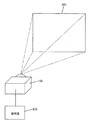
図1は、本発明に係る投影装置の一実施例である液晶プロジェクタの使用状態図を示す。100は液晶プロジェクタに代表される投影装置である。200は、パーソナルコンピュータ(PC)、DVD再生装置又はテレビチューナ等の、画像信号を出力する画像信号源である。300は、投影装置100からの投影画像を映し出すスクリーンである。   FIG. 1 shows a use state diagram of a liquid crystal projector which is an embodiment of a projection apparatus according to the present invention. Reference numeral 100 denotes a projection apparatus represented by a liquid crystal projector. Reference numeral 200 denotes an image signal source that outputs an image signal, such as a personal computer (PC), a DVD playback device, or a television tuner. Reference numeral 300 denotes a screen that displays a projection image from the projection apparatus 100.

図2は、投影装置100の概略構成ブロック図を示す。101は、投影装置100の各ブロックを制御するための制御部である。102は、操作者からの操作を受け付ける操作部である。103は、投影装置100の各ブロックへの電源供給を制御する電源部である。   FIG. 2 shows a schematic block diagram of the projection apparatus 100. Reference numeral 101 denotes a control unit for controlling each block of the projection apparatus 100. Reference numeral 102 denotes an operation unit that receives an operation from the operator. Reference numeral 103 denotes a power supply unit that controls power supply to each block of the projection apparatus 100.

104は、1枚あるいは複数枚の液晶パネル等で構成される液晶部であり、この液晶パネル上に、投影すべき画像が形成される。105は、入力された画像信号に基づいて、液晶部104の液晶パネル上に画像を形成させるための液晶駆動部である。106は、液晶部104に光を供給する光源である。107は、光源106から発せられた光を液晶部104に供給することにより得られた光学像をスクリーン300に投影するための投影光学系である。108は、光源106の光量等を制御するための光源制御部である。   A liquid crystal unit 104 includes one or a plurality of liquid crystal panels, and an image to be projected is formed on the liquid crystal panel. Reference numeral 105 denotes a liquid crystal driving unit for forming an image on the liquid crystal panel of the liquid crystal unit 104 based on the input image signal. A light source 106 supplies light to the liquid crystal unit 104. Reference numeral 107 denotes a projection optical system for projecting an optical image obtained by supplying light emitted from the light source 106 to the liquid crystal unit 104 on the screen 300. Reference numeral 108 denotes a light source control unit for controlling the amount of light of the light source 106 and the like.

109は、投影光学系107に具備されるズームレンズ、フォーカスレンズ、シフトレンズ等の動作を制御し、ズーム倍率、焦点調整及び投影位置制御等を行う光学系制御部である。   An optical system control unit 109 controls operations of a zoom lens, a focus lens, a shift lens, and the like included in the projection optical system 107, and performs zoom magnification, focus adjustment, projection position control, and the like.

110は、PC、DVD再生装置又はテレビチューナ等からのアナログ映像信号を受け付けるアナログ入力部であり、RGB端子、S端子、D端子等からなる。111は、アナログ入力部110により得られた映像信号をデジタル信号に変換するAD変換部である。   Reference numeral 110 denotes an analog input unit that receives an analog video signal from a PC, a DVD playback device, a TV tuner, or the like, and includes an RGB terminal, an S terminal, a D terminal, and the like. Reference numeral 111 denotes an AD converter that converts a video signal obtained by the analog input unit 110 into a digital signal.

112は、PC、DVDプレイヤ又はテレビチューナ等から出力されるデジタル映像信号を受け付けるデジタル入力部であり、DVI端子又はHDMI端子等からなる。HDMI端子では、外部から制御信号も同時に送信されることがあり、これにより映像の制御等が行われることもある。   A digital input unit 112 receives a digital video signal output from a PC, a DVD player, a TV tuner, or the like, and includes a DVI terminal or an HDMI terminal. In the HDMI terminal, a control signal may be transmitted from the outside at the same time, and thereby video control or the like may be performed.

113は、外部から映像データ、画像データ、映像ファイル等の各種の情報データのファイルを受け取ったり、外部に送出したりするUSBインターフェースである。USBインターフェース113には、ポインティングデバイス、キーボード又はUSB型のフラッシュメモリ等が接続可能である。   Reference numeral 113 denotes a USB interface for receiving various information data files such as video data, image data, and video files from the outside, and sending them to the outside. A pointing device, a keyboard, a USB flash memory, or the like can be connected to the USB interface 113.

114は、カード型の記録媒体に対し、映像データ、画像データ及び映像ファイル等の各種の情報データのファイルを読み書きするカードインターフェースである。   A card interface 114 reads and writes various information data files such as video data, image data, and video files with respect to a card-type recording medium.

115は、イントラネット及びインターネットから映像データ、画像データ及び映像ファイル等の各種の情報データのファイル並びにその他の命令信号を送受信する通信部である。通信部115は、例えば、有線LAN又は無線LAN等で構成されている。   Reference numeral 115 denotes a communication unit that transmits and receives various information data files such as video data, image data, and video files and other command signals from the intranet and the Internet. The communication unit 115 is configured by, for example, a wired LAN or a wireless LAN.

116は、映像データ、画像データ及び映像ファイル等の各種の情報データのファイルを保存する内蔵メモリであり、半導体メモリやハードディスク等で構成される。   Reference numeral 116 denotes a built-in memory for storing various information data files such as video data, image data, and video files, and includes a semiconductor memory, a hard disk, and the like.

117〜120は、画像分割部132により分割された4つの分割画像に歪み補正を含む所定の処理を施し、液晶駆動部105に供給する画像処理部である。各画像処理部117〜120は、画像分割部132からの分割画像信号に液晶部104で表示するのに適した補正を行う。例えば、画像信号の画素数を液晶パネルの画素数にあわせて変換する処理がある。また、液晶パネルの交流駆動のため、入力された映像信号のフレーム数を倍にし、液晶パネルによる画像形成に適した補正をする。液晶パネルの交流駆動とは、液晶パネルの液晶にかける電界の方向を交互に入れ替えて表示させる方法であり、液晶パネルは、液晶にかける電圧の方向が正方向(正極性)でも逆方向(負極性)でも画像を生成できる性質を利用したものである。このとき、液晶駆動部105には、正方向用の画像と逆方向用の画像を1枚ずつ送る必要があるので、画像処理部117〜120は、映像信号のフレーム数を倍にする処理を行う。液晶駆動部105は、画像処理部117〜120からの画像信号に基づいて、液晶部104の液晶パネルに画像を形成させる。   Reference numerals 117 to 120 denote image processing units that perform predetermined processing including distortion correction on the four divided images divided by the image dividing unit 132 and supply the processed images to the liquid crystal driving unit 105. Each of the image processing units 117 to 120 performs correction suitable for displaying the divided image signal from the image dividing unit 132 on the liquid crystal unit 104. For example, there is a process of converting the number of pixels of the image signal in accordance with the number of pixels of the liquid crystal panel. Further, since the liquid crystal panel is AC driven, the number of frames of the input video signal is doubled and correction suitable for image formation by the liquid crystal panel is performed. The AC drive of a liquid crystal panel is a method in which the direction of the electric field applied to the liquid crystal of the liquid crystal panel is alternately switched to display, and the liquid crystal panel has a reverse direction (negative polarity) even if the direction of the voltage applied to the liquid crystal is the positive direction (positive polarity). The property that can generate an image is also used. At this time, since it is necessary to send the image for the forward direction and the image for the reverse direction one by one to the liquid crystal drive unit 105, the image processing units 117 to 120 perform processing for doubling the number of frames of the video signal. Do. The liquid crystal driving unit 105 forms an image on the liquid crystal panel of the liquid crystal unit 104 based on the image signals from the image processing units 117 to 120.

121は、投影装置100の重力方向からの変位を検出する傾きセンサであるる。傾きセンサ121は、スクリーンの水平に対する角度が既知であることを前提として、スクリーンに対する投影光軸の傾きを検出する手段として使用される。122は、AD変換部111、デジタル入力部112、USBインターフェース113、カードインターフェース114及び通信部115等から入力されたドキュメントファイルを再生するファイル再生部である。ファイル再生部122は、ドキュメントファイルからユーザに掲示するための画像信号を生成して、画像分割部132に出力する。   Reference numeral 121 denotes an inclination sensor that detects the displacement of the projection apparatus 100 from the direction of gravity. The tilt sensor 121 is used as means for detecting the tilt of the projection optical axis with respect to the screen on the assumption that the angle of the screen with respect to the horizontal is known. A file reproduction unit 122 reproduces a document file input from the AD conversion unit 111, the digital input unit 112, the USB interface 113, the card interface 114, the communication unit 115, and the like. The file reproduction unit 122 generates an image signal to be posted to the user from the document file and outputs the image signal to the image division unit 132.

123は、投影装置100とスクリーン300の距離を検出し、焦点距離を検出する焦点検出部である。124は、スクリーン300の方向を撮像する撮像部である。125は、スクリーン300により反射される光の光量や輝度を計測するスクリーン測光部である。126は、光源106から発せられる光の光量や輝度を計測する光源測光部である。127は、投影装置100本体の状態や警告等を表示する表示部である。128は、表示部127を制御する表示制御部である。   A focus detection unit 123 detects the focal length by detecting the distance between the projection apparatus 100 and the screen 300. Reference numeral 124 denotes an imaging unit that images the direction of the screen 300. Reference numeral 125 denotes a screen photometry unit that measures the amount and luminance of light reflected by the screen 300. Reference numeral 126 denotes a light source photometry unit that measures the amount and luminance of light emitted from the light source 106. Reference numeral 127 denotes a display unit that displays the state of the main body of the projection apparatus 100, a warning, and the like. Reference numeral 128 denotes a display control unit that controls the display unit 127.

129は、投影装置100本体を持ち運んで使用するとき等に、電力を供給するためのバッテリである。130は、外部からの交流電源を所定の電圧に整流して電源部103に供給する電源入力部である。131は、投影装置100本体及び各ブロックの動作時間等を検出するタイマである。   Reference numeral 129 denotes a battery for supplying power when the projection apparatus 100 main body is carried and used. Reference numeral 130 denotes a power supply input unit that rectifies an external AC power supply to a predetermined voltage and supplies the rectified power to the power supply unit 103. A timer 131 detects the operation time of the projection apparatus 100 main body and each block.

132は、デバイス111〜115から入力された画像データを所定数の領域に分割して画像処理部117〜120に供給する画像分割部である。   An image dividing unit 132 divides the image data input from the devices 111 to 115 into a predetermined number of regions and supplies the divided image data to the image processing units 117 to 120.

本実施例では、4つの画像処理部117〜120を具備し、画像分割部132が、1画面を4つの分割画像に分割しているが、分割画像数、即ち画像処理部117〜120の数は、この例に限定されない。AD変換部111及びデジタル入力部112により入力される映像信号又は画像信号は、直接、画像分割部132に供給しても良い。   In the present embodiment, four image processing units 117 to 120 are provided, and the image dividing unit 132 divides one screen into four divided images, but the number of divided images, that is, the number of image processing units 117 to 120 is divided. Is not limited to this example. The video signal or the image signal input from the AD conversion unit 111 and the digital input unit 112 may be directly supplied to the image division unit 132.

投影装置100の通常動作を説明する。操作部102から電源オンが指示されると、投影装置100の制御部101は、電源部103に各ブロックに電源を供給するように指示し、各ブロックを待機状態にする。電源投入後に、制御部101は、光源制御部108に光源106からの発光を開始するように指示する。次に、制御部101は、焦点検出部123により得られた焦点情報等に従い、投影光学系107を調整するよう光学系制御部109に指示する。光学系制御部109では、投影光学系107のズームレンズ、フォーカスレンズ及びシフトレンズを動作させてスクリーン300上に投影光が結像するよう制御する。以上の動作で、投影の準備が整う。   A normal operation of the projection apparatus 100 will be described. When power-on is instructed from the operation unit 102, the control unit 101 of the projection apparatus 100 instructs the power supply unit 103 to supply power to each block, and puts each block in a standby state. After the power is turned on, the control unit 101 instructs the light source control unit 108 to start light emission from the light source 106. Next, the control unit 101 instructs the optical system control unit 109 to adjust the projection optical system 107 in accordance with the focus information obtained by the focus detection unit 123. In the optical system control unit 109, the zoom lens, the focus lens, and the shift lens of the projection optical system 107 are operated to control the projection light to form an image on the screen 300. With the above operation, preparation for projection is completed.

次に、画像分割部132が、例えばデジタル入力部112に入力された画像信号を4つの領域の分割画像に分割し、各分割画像を画像処理部117〜120に供給する。画像処理部117〜120は、それぞれの分割画像に制御部101からの指示に従った画像処理を施し、液晶駆動部105に供給する。画像処理部117〜120による画像処理には、液晶部104に適した解像度への変換、倍速変換、ガンマ補正、輝度むら対策用補正及び台形補正等を含む。   Next, the image dividing unit 132 divides the image signal input to the digital input unit 112, for example, into four divided images, and supplies the divided images to the image processing units 117 to 120. The image processing units 117 to 120 perform image processing according to an instruction from the control unit 101 on each divided image and supply the image to the liquid crystal driving unit 105. Image processing by the image processing units 117 to 120 includes conversion to a resolution suitable for the liquid crystal unit 104, double speed conversion, gamma correction, correction for uneven brightness, trapezoidal correction, and the like.

液晶駆動部105は、画像処理部117〜120からの処理済みの分割画像を再び一画面に合成し、得られた合成画像を液晶部104の液晶パネルで画像を形成するのに適したフォーマットに変換して液晶部104に出力する。液晶部104の液晶パネルは液晶駆動部105からの画像データに基づく画像を表示する。光源106から発せられた光は液晶部104の液晶パネルを透過することで空間強度変調され、投影光学系107によりスクリーン300に投影される。   The liquid crystal driving unit 105 combines the processed divided images from the image processing units 117 to 120 into one screen again, and converts the obtained combined image into a format suitable for forming an image on the liquid crystal panel of the liquid crystal unit 104. The data is converted and output to the liquid crystal unit 104. The liquid crystal panel of the liquid crystal unit 104 displays an image based on the image data from the liquid crystal driving unit 105. Light emitted from the light source 106 is transmitted through the liquid crystal panel of the liquid crystal unit 104 to undergo spatial intensity modulation, and is projected onto the screen 300 by the projection optical system 107.

操作部102から電源オフが指示されると、制御部101は、各ブロックに対し終了処理を行う旨を指示する。終了の準備が整うと、電源部103は、各ブロックへの電源供給を順次終了する。   When the power off is instructed from the operation unit 102, the control unit 101 instructs the block to perform the end process. When preparation for termination is completed, the power supply unit 103 sequentially ends power supply to each block.

デジタル入力部112から入力された映像信号の画像を投影する場合を説明したが、他のデバイス110,113,114,115から入力された映像データを表示する場合も、同様である。   Although the case where the image of the video signal input from the digital input unit 112 is projected has been described, the same applies to the case where the video data input from the other devices 110, 113, 114, 115 is displayed.

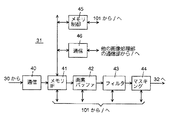
図3は、画像処理部117〜120の概略構成ブロック図を示す。画像処理部117〜120の内部構成は同じである。   FIG. 3 shows a schematic block diagram of the image processing units 117 to 120. The internal configuration of the image processing units 117 to 120 is the same.

30は画像の解像度を変換する解像度変換部である。31はスクリーン300に対する投影装置100の傾きに起因する投影画像の歪みを補正する台形補正部である。32は液晶パネルを交流駆動するために、映像信号のフレーム数を倍にする処理を行う倍速処理部である。33は液晶パネルの電圧対透過率(又は反射率)特性の補正を行うガンマ補正部である。34は液晶パネルの輝度むらや色むらを補正するむら補正部である。   A resolution conversion unit 30 converts the resolution of the image. Reference numeral 31 denotes a trapezoidal correction unit that corrects distortion of the projection image caused by the inclination of the projection apparatus 100 with respect to the screen 300. Reference numeral 32 denotes a double speed processing unit that performs a process of doubling the number of frames of the video signal in order to drive the liquid crystal panel with alternating current. Reference numeral 33 denotes a gamma correction unit for correcting the voltage versus transmittance (or reflectance) characteristics of the liquid crystal panel. Reference numeral 34 denotes an unevenness correction unit that corrects unevenness in luminance and color of the liquid crystal panel.

35は、解像度変換、台形補正及び倍速処理のために1フレームの画像データを格納するメモリである。解像度変換部30、台形補正部31及び倍速処理部32は、メモリバス36を介してメモリ35にデータを読み書きできる。   A memory 35 stores image data of one frame for resolution conversion, keystone correction, and double speed processing. The resolution conversion unit 30, the keystone correction unit 31, and the double speed processing unit 32 can read / write data from / to the memory 35 via the memory bus 36.

解像度変換部30、台形補正部31、倍速処理部32、ガンマ補正部33及びむら補正部34はレジスタバス37を介して制御部101と接続し、制御部101により制御される。   The resolution conversion unit 30, the keystone correction unit 31, the double speed processing unit 32, the gamma correction unit 33, and the unevenness correction unit 34 are connected to the control unit 101 via the register bus 37 and are controlled by the control unit 101.

台形補正部31は、他の画像処理部の台形補正部と画像データの授受を行うためのパスを有する。   The trapezoid correction unit 31 has a path for exchanging image data with the trapezoid correction unit of another image processing unit.

解像度変換部30は、画像分割部132からの対応する分割画像を、液晶パネルの画素数に合う解像度に変換する。台形補正部31は、解像度変換部30の出力画像に、投影装置100の光学系のスクリーン300に対する傾きに起因する投影画像の歪みを相殺する台形補正を施す台形補正部31の詳細な動作は、後述する。   The resolution converting unit 30 converts the corresponding divided image from the image dividing unit 132 into a resolution that matches the number of pixels of the liquid crystal panel. The detailed operation of the trapezoid correction unit 31 that performs trapezoid correction that cancels the distortion of the projection image caused by the tilt of the optical system of the projection apparatus 100 with respect to the screen 300 is performed on the output image of the resolution conversion unit 30. It will be described later.

倍速処理部32は、液晶パネルの交流駆動のために、台形補正部31の出力画像データを倍フレームレートにする。ガンマ補正部33は、倍速処理部32により倍速になった画像データに、液晶パネルの電圧対透過率(又は反射率)特性を補正するガンマ補正を行う。むら補正部34は、ガンマ補正部33の出力画像に、液晶パネルの輝度むら及び色むらの少なくとも一方を補正する処理を施す。むら補正部34の出力画像データは、液晶駆動部105に供給される。本実施例では、画像処理部117〜120からの4系統の出力画像データが液晶駆動部105に供給されることになる。   The double speed processing unit 32 sets the output image data of the trapezoidal correction unit 31 to a double frame rate for AC driving of the liquid crystal panel. The gamma correction unit 33 performs gamma correction for correcting the voltage versus transmittance (or reflectance) characteristics of the liquid crystal panel on the image data that has been doubled by the double speed processing unit 32. The unevenness correction unit 34 performs processing for correcting at least one of luminance unevenness and color unevenness of the liquid crystal panel on the output image of the gamma correction unit 33. The output image data of the unevenness correction unit 34 is supplied to the liquid crystal drive unit 105. In this embodiment, four systems of output image data from the image processing units 117 to 120 are supplied to the liquid crystal driving unit 105.

図4は、台形補正部31の概略構成ブロック図を示す。40は前段の解像度変換部30からの画像データを受信する通信部である。41は、メモリ35にデータを読み書きするメモリインターフェース部である。42は、メモリインターフェース部41からのデータを既定の領域分、バッファリングする画素バッファである。43は、画素バッファ42から受けた既定の領域分の画像データに所定のフィルタ処理を行うフィルタである。44は、画像の縮小によって生じた無信号部にマスク信号を付加するマスキング部である。45は、制御部101の指示に従いメモリ35を制御するメモリ制御部である。46は、他の画像処理部の台形補正部と画像データを送受信する通信部である。   FIG. 4 shows a schematic block diagram of the trapezoidal correction unit 31. Reference numeral 40 denotes a communication unit that receives image data from the previous resolution conversion unit 30. A memory interface unit 41 reads / writes data from / to the memory 35. A pixel buffer 42 buffers data from the memory interface unit 41 for a predetermined area. A filter 43 performs a predetermined filter process on image data for a predetermined area received from the pixel buffer 42. Reference numeral 44 denotes a masking unit that adds a mask signal to a non-signal portion generated by image reduction. A memory control unit 45 controls the memory 35 in accordance with an instruction from the control unit 101. A communication unit 46 transmits / receives image data to / from the trapezoid correction unit of another image processing unit.

図4に示す台形補正部31の詳細な動作を説明する。通信部40は、解像度変換部30からの画像データを取り込み、メモリインターフェース部41に供給する。メモリインターフェース部41は、制御部101による指示に従い、通信部40からの画像データをメモリ35に書き込むのに最適な形式に変換する。メモリインターフェース部41はまた、メモリ制御部45からの指示に従い、メモリ35から読み出した画像データを後段の処理に適した形式に変換する。   The detailed operation of the trapezoid correction unit 31 shown in FIG. 4 will be described. The communication unit 40 takes in the image data from the resolution conversion unit 30 and supplies it to the memory interface unit 41. The memory interface unit 41 converts the image data from the communication unit 40 into an optimal format for writing to the memory 35 in accordance with an instruction from the control unit 101. The memory interface unit 41 also converts the image data read from the memory 35 into a format suitable for subsequent processing in accordance with an instruction from the memory control unit 45.

画素バッファ42は、メモリインターフェース部41から出力される画像データを、縦横に既定の大きさを有する領域分、展開される。この既定の大きさは、制御部101の指示に従って決定される。   The pixel buffer 42 expands the image data output from the memory interface unit 41 by a region having a predetermined size vertically and horizontally. This predetermined size is determined according to an instruction from the control unit 101.

フィルタ43は、画素バッファ42の出力画像データに2次元フィルタ処理を施す。具体的には、フィルタ43により、台形補正に必要な縮小拡大処理及びこの処理に伴うエッジ強調、平滑化、エッジスムージング並びに折り返し歪み除去等を行う。なお、台形補正に必要な縮小拡大の倍率は、傾きセンサ121で検出される投影装置100のスクリーンに対する投影光軸の傾き角度に応じて決定される。   The filter 43 performs a two-dimensional filter process on the output image data of the pixel buffer 42. Specifically, the filter 43 performs reduction / enlargement processing necessary for trapezoidal correction, edge enhancement, smoothing, edge smoothing, aliasing distortion removal, and the like accompanying this processing. Note that the reduction / enlargement magnification necessary for the keystone correction is determined according to the inclination angle of the projection optical axis with respect to the screen of the projection apparatus 100 detected by the inclination sensor 121.

フィルタ43で画像縮小処理を行った場合、無信号部が生じる。マスキング部44は、その無信号部にブランキング等のマスク信号を付加する。マスキング部44の出力は倍速処理部32へ送られる。   When the image reduction process is performed by the filter 43, a non-signal portion is generated. The masking unit 44 adds a mask signal such as blanking to the non-signal portion. The output of the masking unit 44 is sent to the double speed processing unit 32.

図5を参照して、台形補正部31の動作を具体的に説明する。図5は、原画像を縦横に2分割した合計4つの分割画像の分割と変形の例を示す。すなわち、図5は、画像処理部117〜120の入力画像と、各画像処理部117〜120の出力画像(分割画像)の関係をも示す。図5で、破線は、原画像を縦横で均等に分割する均等分割線又は均等分割境界線を示し、一点鎖線は、台形補正対象範囲を分割する実質分割線又は実質分割境界線を示す。実質分割線は、投影装置100がスクリーン300に対する傾きの量に応じた量だけ、均等分割線の位置から移動する。   With reference to FIG. 5, the operation of the trapezoidal correction unit 31 will be specifically described. FIG. 5 shows an example of division and deformation of a total of four divided images obtained by dividing the original image into two vertically and horizontally. That is, FIG. 5 also shows the relationship between the input images of the image processing units 117 to 120 and the output images (divided images) of the image processing units 117 to 120. In FIG. 5, broken lines indicate equal dividing lines or equal dividing boundary lines that equally divide the original image vertically and horizontally, and alternate long and short dashed lines indicate substantial dividing lines or substantial dividing boundary lines that divide the trapezoid correction target range. The substantial dividing line moves from the position of the uniform dividing line by an amount corresponding to the amount of inclination of the projection apparatus 100 with respect to the screen 300.

台形補正部31のフィルタ43の二次元フィルタ処理(空間フィルタ処理)のためには、目的範囲の画像データのみならず、その周囲の画素データをも必要とする。以下の説明では、理解を容易にするために目的範囲の画像データをフィルタ43に入力するように説明しているが、実際には、目的範囲の画像データの外側の一定範囲の画素データをもフィルタ43に入力する。   For the two-dimensional filter processing (spatial filter processing) of the filter 43 of the trapezoid correction unit 31, not only image data in the target range but also surrounding pixel data is required. In the following description, the image data of the target range is described as being input to the filter 43 for easy understanding, but actually, the pixel data of a certain range outside the image data of the target range is also included. Input to the filter 43.

制御部101は、投影装置100のスクリーン300に対する傾きの方向と程度に応じて、台形補正の対象となる、原画像の実質的な分割境界線を決定する。図5(a)は、投影装置100がスクリーン300に対して上向きに傾いたときの入力画像(原画像)を示し、同(b)は、台形補正結果を示す。投影装置100がスクリーン300に対して上向きに傾いているときには、図5(a)に示すように、縦方向の分割境界線を原画像の中心位置から上側に投影装置100の傾き角度に応じた量だけシフトする必要がある。   The control unit 101 determines a substantial division boundary line of the original image to be trapezoidally corrected according to the direction and degree of inclination of the projection apparatus 100 with respect to the screen 300. FIG. 5A shows an input image (original image) when the projection apparatus 100 is tilted upward with respect to the screen 300, and FIG. 5B shows a trapezoidal correction result. When the projection apparatus 100 is tilted upward with respect to the screen 300, as shown in FIG. 5A, the vertical division boundary line is raised upward from the center position of the original image according to the tilt angle of the projection apparatus 100. It is necessary to shift by the amount.

画像分割部132は、入力画像(原画像)を縦横に均等に2分割する均等分割線で分割し、同じ大きさの4つの分割画像を生成する。すなわち、画像分割部132は、領域501,502からなる分割画像、領域503からなる分割画像、領域504,505からなる分割画像、及び領域506からなる分割画像を生成する。領域502,505と領域503,506との間の境界線は台形補正の対象範囲を規定する実質分割境界線であり、制御部101が、投影装置100のスクリーン300に対する傾きの方向と程度に応じて決定する。   The image dividing unit 132 divides the input image (original image) by equal dividing lines that equally divide the image vertically and horizontally into four divided images having the same size. That is, the image dividing unit 132 generates a divided image made up of the regions 501 and 502, a divided image made up of the region 503, a divided image made up of the regions 504 and 505, and a divided image made up of the region 506. The boundary lines between the regions 502 and 505 and the regions 503 and 506 are substantially divided boundary lines that define the target range for trapezoidal correction, and the control unit 101 depends on the direction and degree of inclination of the projection apparatus 100 with respect to the screen 300. To decide.

画像分割部132は、領域501,502からなる分割画像を画像処理部117に供給し、領域503からなる分割画像を画像処理部118に供給する。画像分割部132はまた、領域504,505からなる分割画像を画像処理部119に供給し、領域506からなる分割画像を画像処理部120に供給する。但し、前述したように、二次元フィルタ処理のためには、目的範囲の外側に位置する画素データも必要となるので、画像分割部132から各画像処理部117〜120には、分割画像以外に、その周囲の画素データも供給される。   The image dividing unit 132 supplies the divided image including the regions 501 and 502 to the image processing unit 117 and supplies the divided image including the region 503 to the image processing unit 118. The image dividing unit 132 also supplies the divided image including the regions 504 and 505 to the image processing unit 119 and supplies the divided image including the region 506 to the image processing unit 120. However, as described above, pixel data located outside the target range is also required for the two-dimensional filter processing, so that the image dividing unit 132 to each of the image processing units 117 to 120 includes other than the divided image. The surrounding pixel data is also supplied.

画像処理部117の台形補正部31では、フィルタ43が、領域501の画像部分を変形及び縮小して図5(b)に示す領域507の形状に変換する。マスキング部44が、フィルタ43のフィルタ処理で空いた領域541(図5(b))にブランキングを付加する。   In the trapezoid correction unit 31 of the image processing unit 117, the filter 43 deforms and reduces the image portion of the region 501 and converts it into the shape of the region 507 shown in FIG. The masking unit 44 adds blanking to the area 541 (FIG. 5B) that is vacated by the filter processing of the filter 43.

画像処理部118の台形補正部31では、通信部46を介して画像処理部117から領域502の画像部分を受信する。フィルタ43は、画像処理部117からの領域502の画像部分と、画像分割部132からの領域503の画像部分を合わせて変形及び縮小して、図5(b)に示す領域508の形状に変換する。マスキング部44が、フィルタ43のフィルタ処理で空いた領域542(図5(b))にブランキングを付加する。   The trapezoid correction unit 31 of the image processing unit 118 receives the image portion of the region 502 from the image processing unit 117 via the communication unit 46. The filter 43 transforms and reduces the image portion of the region 502 from the image processing unit 117 and the image portion of the region 503 from the image dividing unit 132, and converts them into the shape of the region 508 shown in FIG. To do. The masking unit 44 adds blanking to a region 542 (FIG. 5B) that is freed by the filter processing of the filter 43.

画像処理部119の台形補正部31では、フィルタ43が、領域504の画像部分を変形及び縮小して図5(b)に示す領域509の形状に変換する。マスキング部44が、フィルタ43のフィルタ処理で空いた領域543(図5(b))にブランキングを付加する。   In the trapezoid correction unit 31 of the image processing unit 119, the filter 43 deforms and reduces the image portion of the region 504 and converts it into the shape of the region 509 shown in FIG. The masking unit 44 adds blanking to the area 543 (FIG. 5B) that is vacated by the filter processing of the filter 43.

画像処理部120の台形補正部31では、通信部46を介して画像処理部119から領域505の画像部分を受信する。フィルタ43は、画像処理部119からの領域505の画像部分と、画像分割部132からの領域506の画像部分を合わせて変形及び縮小して、図5(b)に示す領域510の形状に変換する。マスキング部44が、フィルタ43のフィルタ処理で空いた領域544(図5(b))にブランキングを付加する。   The trapezoid correction unit 31 of the image processing unit 120 receives the image portion of the area 505 from the image processing unit 119 via the communication unit 46. The filter 43 deforms and reduces the image portion of the region 505 from the image processing unit 119 and the image portion of the region 506 from the image dividing unit 132, and converts them into the shape of the region 510 shown in FIG. To do. The masking unit 44 adds blanking to a region 544 (FIG. 5B) that is freed by the filter processing of the filter 43.

このように、本実施例では、投影装置100のスクリーン300に対する傾きの方向と程度に応じて決定される分割境界線で分割される分割画像を各画像処理部117〜120で台形補正する。図5(a)に示すでは、画像処理部117が、領域501を台形補正し、画像処理部118が、領域502,503を台形補正する。また、画像処理部119が、領域504を台形補正し、画像処理部120が領域505,506を台形補正する。   As described above, in this embodiment, the image processing units 117 to 120 trapezoidally correct the divided images divided by the division boundary lines determined according to the direction and degree of inclination of the projection apparatus 100 with respect to the screen 300. In FIG. 5A, the image processing unit 117 corrects the area 501 with a keystone, and the image processing unit 118 corrects the areas 502 and 503 with a keystone. In addition, the image processing unit 119 corrects the keystone of the region 504, and the image processing unit 120 corrects the keystones of the regions 505 and 506.

先に説明したように、フィルタ43による2次元フィルタ処理のためには、目的範囲の画像データに加えて、その周囲の画素データも必要とする。例えば、領域502、503からなる画像データ部分を画像処理部118で2次元フィルタ処理を施す場合、端部の画像データ生成には領域501の下端、領域505の右端及び領域506の右端の画素データが必要である。画像処理部118は、画像処理部117から領域502の画像データ部分とその周囲(領域501の下端及び領域505の右端)の画素データを受け取る。領域506の右端の画素データは、画像分割部132から供給されているので、他の画像処理部117,119,120から受け取る必要は無い。   As described above, for the two-dimensional filter processing by the filter 43, in addition to the image data in the target range, the surrounding pixel data is also required. For example, when the image processing unit 118 performs two-dimensional filter processing on the image data portion composed of the regions 502 and 503, pixel data at the lower end of the region 501, the right end of the region 505, and the right end pixel of the region 506 are used to generate image data at the end. is necessary. The image processing unit 118 receives the image data portion of the area 502 and the surrounding pixel data (the lower end of the area 501 and the right end of the area 505) from the image processing section 117. Since the pixel data at the right end of the area 506 is supplied from the image dividing unit 132, it is not necessary to receive it from the other image processing units 117, 119, and 120.

図5(c)は、投影装置100がスクリーン300に対して下向きに傾いたときの入力画像(原画像)を示し、同(b)は、台形補正結果を示す。投影装置100がスクリーン300に対して下向きに傾いているときには、図5(c)に示すように、縦方向の分割境界線を原画像の中心位置から下側に投影装置100の傾き角度に応じた量だけシフトする必要がある。   FIG. 5C shows an input image (original image) when the projection apparatus 100 is tilted downward with respect to the screen 300, and FIG. 5B shows a trapezoidal correction result. When the projection apparatus 100 is tilted downward with respect to the screen 300, as shown in FIG. 5C, the vertical division boundary line is moved downward from the center position of the original image according to the tilt angle of the projection apparatus 100. Need to shift by the same amount.

このときも、画像分割部132は、入力画像(原画像)を縦横に均等に2分割する均等分割線で分割し、同じ大きさの4つの分割画像を生成する。すなわち、画像分割部132は、領域511からなる分割画像、領域512,513からなる分割画像、領域514からなる分割画像、及び領域515,516からなる分割画像を生成する。領域512,515と領域513,516との間の境界線は、台形補正の対象範囲を規定する実質分割境界線であり、制御部101が、投影装置100のスクリーン300に対する傾きの方向と程度に応じて決定する。   Also at this time, the image dividing unit 132 divides the input image (original image) by equal dividing lines that equally divide the input image into two vertically and horizontally, and generates four divided images having the same size. In other words, the image dividing unit 132 generates a divided image composed of the area 511, a divided image composed of the areas 512 and 513, a divided image composed of the area 514, and a divided image composed of the areas 515 and 516. The boundary lines between the areas 512 and 515 and the areas 513 and 516 are substantially divided boundary lines that define the target range of trapezoidal correction, and the control unit 101 determines the direction and degree of inclination of the projection apparatus 100 with respect to the screen 300. Decide accordingly.

画像分割部132は、領域511からなる分割画像を画像処理部117に供給し、領域512,513からなる分割画像を画像処理部118に供給する。画像分割部132はまた、領域514からなる分割画像を画像処理部119に供給し、領域515,516からなる分割画像を画像処理部120に供給する。図5(a9,(b)の場合と同様に、二次元フィルタ処理のために、画像分割部132から各画像処理部117〜120には、分割画像以外に、その周囲の画素データも供給される。   The image dividing unit 132 supplies the divided image including the region 511 to the image processing unit 117 and supplies the divided image including the regions 512 and 513 to the image processing unit 118. The image dividing unit 132 also supplies the divided image including the region 514 to the image processing unit 119 and supplies the divided image including the regions 515 and 516 to the image processing unit 120. As in the case of FIGS. 5A and 5B, in addition to the divided image, the surrounding pixel data is also supplied from the image dividing unit 132 to each of the image processing units 117 to 120 for the two-dimensional filter processing. The

画像処理部117の台形補正部31では、通信部46を介して画像処理部118から領域512の画像部分を受信する。フィルタ43は、画像処理部118からの領域512の画像部分と、画像分割部132からの領域511の画像部分を合わせて変形及び縮小して、図5(d)に示す領域517の形状に変換する。マスキング部44が、フィルタ43のフィルタ処理で空いた領域545(図5(d))にブランキングを付加する。   The keystone correction unit 31 of the image processing unit 117 receives the image portion of the region 512 from the image processing unit 118 via the communication unit 46. The filter 43 transforms the image portion of the region 512 from the image processing unit 118 and the image portion of the region 511 from the image dividing unit 132 into a shape of the region 517 shown in FIG. To do. The masking unit 44 adds blanking to a region 545 (FIG. 5D) that is vacated by the filter processing of the filter 43.

画像処理部118の台形補正部31では、フィルタ43が、領域513の画像部分を変形及び縮小して図5(d)に示す領域518の形状に変換する。マスキング部44が、フィルタ43のフィルタ処理で空いた領域546(図5(d))にブランキングを付加する。   In the trapezoidal correction unit 31 of the image processing unit 118, the filter 43 transforms and reduces the image portion of the region 513 into the shape of the region 518 shown in FIG. The masking unit 44 adds blanking to a region 546 (FIG. 5D) vacated by the filter processing of the filter 43.

画像処理部119の台形補正部31では、通信部46を介して画像処理部120から領域515の画像部分を受信する。フィルタ43は、画像処理部120からの領域515の画像部分と、画像分割部132からの領域514の画像部分を合わせて変形及び縮小して、図5(d)に示す領域519の形状に変換する。マスキング部44が、フィルタ43のフィルタ処理で空いた領域547(図5(d))にブランキングを付加する。   The trapezoid correction unit 31 of the image processing unit 119 receives the image portion of the region 515 from the image processing unit 120 via the communication unit 46. The filter 43 deforms and reduces the image portion of the region 515 from the image processing unit 120 and the image portion of the region 514 from the image dividing unit 132, and converts them into the shape of the region 519 shown in FIG. To do. The masking unit 44 adds blanking to a region 547 (FIG. 5D) that is vacant by the filter processing of the filter 43.

画像処理部120の台形補正部31では、フィルタ43が、領域516の画像部分を変形及び縮小して図5(d)に示す領域520の形状に変換する。マスキング部44が、フィルタ43のフィルタ処理で空いた領域548(図5(d))にブランキングを付加する。   In the trapezoidal correction unit 31 of the image processing unit 120, the filter 43 transforms and reduces the image portion of the region 516 into the shape of the region 520 shown in FIG. The masking unit 44 adds blanking to a region 548 (FIG. 5D) that is vacated by the filter processing of the filter 43.

図5(e)は、投影装置100がスクリーン300に対して右向きに傾いたときの入力画像(原画像)を示し、同(f)は、台形補正結果を示す。投影装置100がスクリーン300に対して右向きに傾いているときには、図5(e)に示すように、横方向の分割境界線を原画像の中心位置から右側に投影装置100の傾き角度に応じた量だけシフトする必要がある。   FIG. 5E shows an input image (original image) when the projection apparatus 100 is tilted to the right with respect to the screen 300, and FIG. 5F shows a trapezoidal correction result. When the projection apparatus 100 is tilted to the right with respect to the screen 300, as shown in FIG. 5E, the horizontal dividing boundary line is set to the right from the center position of the original image according to the tilt angle of the projection apparatus 100. It is necessary to shift by the amount.

画像分割部132は、入力画像(原画像)を縦横に均等に2分割する均等分割線で分割し、同じ大きさの4つの分割画像を生成する。すなわち、画像分割部132は、領域521,522からなる分割画像、領域523,524からなる分割画像、領域525からなる分割画像、及び領域526からなる分割画像を生成する。領域521,523と領域522,524との間の境界線は台形補正の対象範囲を規定する実質分割境界線であり、制御部101が、投影装置100のスクリーン300に対する傾きの方向と程度に応じて決定する。   The image dividing unit 132 divides the input image (original image) by equal dividing lines that equally divide the image vertically and horizontally into four divided images having the same size. That is, the image dividing unit 132 generates a divided image including the areas 521 and 522, a divided image including the areas 523 and 524, a divided image including the area 525, and a divided image including the area 526. The boundary lines between the areas 521 and 523 and the areas 522 and 524 are substantially divided boundary lines that define the target range of the trapezoidal correction, and the control unit 101 depends on the direction and degree of inclination of the projection apparatus 100 with respect to the screen 300 To decide.

画像分割部132は、領域521,522からなる分割画像を画像処理部117に供給し、領域523,524からなる分割画像を画像処理部118に供給する。画像分割部132はまた、領域525からなる分割画像を画像処理部119に供給し、領域526からなる分割画像を画像処理部120に供給する。但し、前述したように、二次元フィルタ処理のためには、目的範囲の外側に位置する画素データも必要となるので、画像分割部132から各画像処理部117〜120には、分割画像以外に、その周囲の画素データも供給される。   The image dividing unit 132 supplies the divided image including the regions 521 and 522 to the image processing unit 117 and supplies the divided image including the regions 523 and 524 to the image processing unit 118. The image dividing unit 132 also supplies the divided image including the region 525 to the image processing unit 119 and supplies the divided image including the region 526 to the image processing unit 120. However, as described above, pixel data located outside the target range is also required for the two-dimensional filter processing, so that the image dividing unit 132 to each of the image processing units 117 to 120 includes other than the divided image. The surrounding pixel data is also supplied.

画像処理部117の台形補正部31では、フィルタ43が、領域521の画像部分を変形及び縮小して図5(f)に示す領域527の形状に変換する。マスキング部44が、フィルタ43のフィルタ処理で空いた領域549(図5(f))にブランキングを付加する。   In the trapezoidal correction unit 31 of the image processing unit 117, the filter 43 transforms and reduces the image portion of the region 521 into the shape of the region 527 shown in FIG. The masking unit 44 adds blanking to a region 549 (FIG. 5 (f)) freed by the filter processing of the filter 43.

画像処理部118の台形補正部31では、フィルタ43が、領域523の画像部分を変形及び縮小して図5(f)に示す領域528の形状に変換する。マスキング部44が、フィルタ43のフィルタ処理で空いた領域550(図5(f))にブランキングを付加する。   In the trapezoidal correction unit 31 of the image processing unit 118, the filter 43 transforms and reduces the image portion of the region 523 into the shape of the region 528 shown in FIG. The masking unit 44 adds blanking to a region 550 (FIG. 5 (f)) freed by the filter processing of the filter 43.

画像処理部119の台形補正部31では、通信部46を介して画像処理部117から領域522の画像部分を受信する。フィルタ43は、画像処理部117からの領域522の画像部分と、画像分割部132からの領域525の画像部分を合わせて変形及び縮小して、図5(f)に示す領域529の形状に変換する。マスキング部44が、フィルタ43のフィルタ処理で空いた領域551(図5(f))にブランキングを付加する。   The trapezoid correction unit 31 of the image processing unit 119 receives the image portion of the region 522 from the image processing unit 117 via the communication unit 46. The filter 43 deforms and reduces the image portion of the region 522 from the image processing unit 117 and the image portion of the region 525 from the image dividing unit 132, and converts them into the shape of the region 529 shown in FIG. To do. The masking unit 44 adds blanking to the area 551 (FIG. 5 (f)) freed by the filter processing of the filter 43.

画像処理部120の台形補正部31では、通信部46を介して画像処理部118から領域524の画像部分を受信する。フィルタ43は、画像処理部118からの領域524の画像部分と、画像分割部132からの領域526の画像部分を合わせて変形及び縮小して、図5(f)に示す領域530の形状に変換する。マスキング部44が、フィルタ43のフィルタ処理で空いた領域552(図5(f))にブランキングを付加する。   The trapezoid correction unit 31 of the image processing unit 120 receives the image portion of the region 524 from the image processing unit 118 via the communication unit 46. The filter 43 transforms and reduces the image portion of the region 524 from the image processing unit 118 and the image portion of the region 526 from the image dividing unit 132, and converts them into the shape of the region 530 shown in FIG. To do. The masking unit 44 adds blanking to a region 552 (FIG. 5 (f)) freed by the filter processing of the filter 43.

図5(g)は、投影装置100がスクリーン300に対して左向きに傾いたときの入力画像(原画像)を示し、同(h)は、台形補正結果を示す。投影装置100がスクリーン300に対して左向きに傾いているときには、図5(g)に示すように、横方向の分割境界線を原画像の中心位置から左側に投影装置100の傾き角度に応じた量だけシフトする必要がある。   FIG. 5G shows an input image (original image) when the projection apparatus 100 is tilted leftward with respect to the screen 300, and FIG. 5H shows a trapezoidal correction result. When the projection apparatus 100 is tilted to the left with respect to the screen 300, as shown in FIG. 5G, the horizontal dividing boundary line is leftward from the center position of the original image according to the tilt angle of the projection apparatus 100. It is necessary to shift by the amount.

画像分割部132は、入力画像(原画像)を縦横に均等に2分割する均等分割線で分割し、同じ大きさの4つの分割画像を生成する。すなわち、画像分割部132は、領域531からなる分割画像、領域532からなる分割画像、領域533,534からなる分割画像、及び領域535,536からなる分割画像を生成する。領域533,535と領域534,536との間の境界線は台形補正の対象範囲を規定する実質分割境界線であり、制御部101が、投影装置100のスクリーン300に対する傾きの方向と程度に応じて決定する。   The image dividing unit 132 divides the input image (original image) by equal dividing lines that equally divide the image vertically and horizontally into four divided images having the same size. That is, the image dividing unit 132 generates a divided image made up of the region 531, a divided image made up of the region 532, a divided image made up of the regions 533 and 534, and a divided image made up of the regions 535 and 536. The boundary lines between the regions 533 and 535 and the regions 534 and 536 are substantially divided boundary lines that define the target range of the trapezoidal correction, and the control unit 101 depends on the direction and degree of inclination of the projection device 100 with respect to the screen 300. To decide.

画像分割部132は、領域531からなる分割画像を画像処理部117に供給し、領域532からなる分割画像を画像処理部118に供給する。画像分割部132はまた、領域533,534からなる分割画像を画像処理部119に供給し、領域535,536からなる分割画像を画像処理部120に供給する。但し、前述したように、二次元フィルタ処理のためには、目的範囲の外側に位置する画素データも必要となるので、画像分割部132から各画像処理部117〜120には、分割画像以外に、その周囲の画素データも供給される。   The image dividing unit 132 supplies the divided image including the region 531 to the image processing unit 117, and supplies the divided image including the region 532 to the image processing unit 118. The image dividing unit 132 also supplies the divided image including the regions 533 and 534 to the image processing unit 119 and supplies the divided image including the regions 535 and 536 to the image processing unit 120. However, as described above, pixel data located outside the target range is also required for the two-dimensional filter processing, so that the image dividing unit 132 to each of the image processing units 117 to 120 includes other than the divided image. The surrounding pixel data is also supplied.

画像処理部117の台形補正部31では、通信部46を介して画像処理部119から領域533の画像部分を受信する。フィルタ43は、画像処理部119からの領域533の画像部分と、画像分割部132からの領域531の画像部分を合わせて変形及び縮小して、図5(h)に示す領域537の形状に変換する。マスキング部44が、フィルタ43のフィルタ処理で空いた領域553(図5(h))にブランキングを付加する。   The keystone correction unit 31 of the image processing unit 117 receives the image portion of the region 533 from the image processing unit 119 via the communication unit 46. The filter 43 transforms the image portion of the region 533 from the image processing unit 119 and the image portion of the region 531 from the image dividing unit 132 into a shape of the region 537 shown in FIG. To do. The masking unit 44 adds blanking to a region 553 (FIG. 5 (h)) vacated by the filter processing of the filter 43.

画像処理部118の台形補正部31では、通信部46を介して画像処理部120から領域535の画像部分を受信する。フィルタ43は、画像処理部120からの領域535の画像部分と、画像分割部132からの領域532の画像部分を合わせて変形及び縮小して、図5(h)に示す領域538の形状に変換する。マスキング部44が、フィルタ43のフィルタ処理で空いた領域554(図5(h))にブランキングを付加する。   The trapezoid correction unit 31 of the image processing unit 118 receives the image portion of the region 535 from the image processing unit 120 via the communication unit 46. The filter 43 deforms and reduces the image portion of the region 535 from the image processing unit 120 and the image portion of the region 532 from the image dividing unit 132, and converts them into the shape of the region 538 shown in FIG. To do. The masking unit 44 adds blanking to a region 554 (FIG. 5 (h)) vacated by the filter processing of the filter 43.

画像処理部119の台形補正部31では、フィルタ43が、領域534の画像部分を変形及び縮小して図5(h)に示す領域539の形状に変換する。マスキング部44が、フィルタ43のフィルタ処理で空いた領域555(図5(h))にブランキングを付加する。   In the trapezoidal correction unit 31 of the image processing unit 119, the filter 43 transforms and reduces the image portion of the region 534 into the shape of the region 539 shown in FIG. The masking unit 44 adds blanking to a region 555 (FIG. 5 (h)) that is freed by the filter processing of the filter 43.

画像処理部120の台形補正部31では、フィルタ43が、領域536の画像部分を変形及び縮小して図5(h)に示す領域540の形状に変換する。マスキング部44が、フィルタ43のフィルタ処理で空いた領域556(図5(h))にブランキングを付加する。   In the trapezoidal correction unit 31 of the image processing unit 120, the filter 43 transforms and reduces the image portion of the region 536 into the shape of the region 540 shown in FIG. The masking unit 44 adds blanking to the area 556 (FIG. 5 (h)) vacated by the filter processing of the filter 43.

図6は、図5(a),(b)に示す例で、分割画像データを画像分割部132から取り込み、画像処理部117〜120で台形補正を施して出力する動作のタイムチャートである。図6(a)は、画像処理部117〜120のメモリ35に分割画像データを書き込む動作のタイムチャートである。   FIGS. 6A and 6B are time charts of operations of taking the divided image data from the image dividing unit 132, performing trapezoid correction by the image processing units 117 to 120, and outputting the divided image data in the example shown in FIGS. 5A and 5B. FIG. 6A is a time chart of an operation for writing the divided image data in the memory 35 of the image processing units 117 to 120.

垂直同期信号(VSNYC)に同期して、画像分割部132からの領域501,502からなる画像データが、画面上部から下部の順に画像処理部117のメモリ35に書き込まれる。画像処理部118のメモリ35には、画像分割部132からの領域503の画像データが画面上部から下部の順に書き込まれる。画像処理部119のメモリ35には、画像分割部132からの領域504,505の画像データが画面上部から下部の順に書き込まれる。画像処理部120のメモリ35には、画像分割部132からの領域506の画像データが画面上部から下部の順に書き込まれる。   In synchronization with the vertical synchronization signal (VSNYC), the image data composed of the areas 501 and 502 from the image dividing unit 132 is written in the memory 35 of the image processing unit 117 in order from the top to the bottom of the screen. In the memory 35 of the image processing unit 118, the image data of the area 503 from the image dividing unit 132 is written in the order from the top to the bottom of the screen. In the memory 35 of the image processing unit 119, the image data of the areas 504 and 505 from the image dividing unit 132 are written in the order from the top to the bottom of the screen. In the memory 35 of the image processing unit 120, the image data of the area 506 from the image dividing unit 132 is written in the order from the top to the bottom of the screen.

図6(b)は、画像処理部117〜120のメモリ35から画像データを読み出す動作のタイムチャートである。   FIG. 6B is a time chart of an operation of reading image data from the memory 35 of the image processing units 117 to 120.

垂直同期信号(VSNYC)に同期して、画像処理部117のメモリ35からは、まず画像処理部118に送信すべき領域502の画像データが読み出される。画像処理部117の通信部46は、メモリ35から読み出さした領域502の画像データを画像処理部118の通信部46に転送する。続いて、領域502の画像データは、画像処理部118のメモリ制御部45の制御下に、画像処理部118のメモリ35に書き込まれる。   In synchronization with the vertical synchronization signal (VSNYC), the image data of the area 502 to be transmitted to the image processing unit 118 is first read from the memory 35 of the image processing unit 117. The communication unit 46 of the image processing unit 117 transfers the image data in the area 502 read from the memory 35 to the communication unit 46 of the image processing unit 118. Subsequently, the image data in the area 502 is written into the memory 35 of the image processing unit 118 under the control of the memory control unit 45 of the image processing unit 118.

引き続き、画像処理部117では、領域501の画像データがメモリ35から読み出されて台形補正され、上述の通り領域507の補正画像データと領域541のマスキングが生成される。同時に、画像処理部118では、画像処理部117からの領域502の画像データと領域503の画像データがメモリ35から読み出されて台形補正され、上述の通り領域508の補正画像データと領域542のマスキングが生成される。   Subsequently, the image processing unit 117 reads the image data of the area 501 from the memory 35 and corrects the keystone, and generates the corrected image data of the area 507 and the masking of the area 541 as described above. At the same time, the image processing unit 118 reads the image data of the area 502 and the image data of the area 503 from the image processing unit 117 from the memory 35 and corrects the keystone, and as described above, the corrected image data of the area 508 and the corrected image data of the area 542 Masking is generated.

画像処理部119、120の動作も同様であるので、説明は省略する。   Since the operations of the image processing units 119 and 120 are the same, description thereof will be omitted.

画像処理部118、120では、それぞれのメモリ35に書き込んだ画像データに加え、それぞれ画像処理部117、119からの画像データも処理する。従って、台形補正処理を1垂直期間で完了させるためには、メモリ35からのデータの読み出しは、書き込み時よりも高速に行う必要がある。   The image processing units 118 and 120 process the image data from the image processing units 117 and 119 in addition to the image data written in the respective memories 35. Therefore, in order to complete the trapezoidal correction process in one vertical period, it is necessary to read data from the memory 35 at a higher speed than at the time of writing.

図5(c)〜(h)に示すケースも、基本的に、図6(a),(b)と同様の動作で行われる。   The cases shown in FIGS. 5C to 5H are basically performed in the same manner as in FIGS. 6A and 6B.

図7は、本実施例の動作を表すフローチャートを示す。   FIG. 7 is a flowchart showing the operation of this embodiment.

ステップS702で、制御部101は、傾きセンサ121から傾きデータ又は傾き検出値を取得する。傾きセンサ121の代わりに、傾き量算出のためのテスト画像を投影し、撮像部124でスクリーン300の投影画像を撮像し、その投影画像の形状を制御部101で解析することでも、傾きを決定できる。   In step S <b> 702, the control unit 101 acquires inclination data or an inclination detection value from the inclination sensor 121. Instead of using the tilt sensor 121, a test image for calculating the tilt amount is projected, the projected image of the screen 300 is captured by the imaging unit 124, and the shape of the projected image is analyzed by the control unit 101 to determine the tilt. it can.

ステップS703で、信号源200からの映像信号が投影装置100に入力する。ステップS704で、画像分割部132が映像信号の各画面を分割し、各画像処理部117〜120のメモリ35に、対応する画像データを書き込む。   In step S <b> 703, the video signal from the signal source 200 is input to the projection apparatus 100. In step S704, the image dividing unit 132 divides each screen of the video signal, and writes the corresponding image data in the memory 35 of each of the image processing units 117 to 120.

ステップS705で、制御部101は、傾きセンサ121からの傾きデータから、画像処理部117〜120の間で授受すべき画像データの範囲(例えば、実質分割線の位置)を決定する。つまり、傾きがある場合、台形補正を行うことになるので、先に説明したように、画像処理部117〜120間で画像データを送受信する必要が生じる。   In step S <b> 705, the control unit 101 determines the range of image data (for example, the position of the substantial dividing line) to be exchanged between the image processing units 117 to 120 from the tilt data from the tilt sensor 121. In other words, when there is an inclination, keystone correction is performed, so that it is necessary to transmit / receive image data between the image processing units 117 to 120 as described above.

ステップS706で、制御部101は、傾きの方向から各画像処理部117〜120が画像データを他の画像処理部117〜120から受信するのか送信するのかを判別する。例として画像処理部117を基準に考える。投影装置100がスクリーン300に対して上向きに傾いている場合、図5(a)に示すように、画像処理部117は、画像処理部118に領域502の画像データを送信する。投影装置100がスクリーン300に対して下向きに傾いている場合、図5(c)に示すように、画像処理部117は、画像処理部118から領域512の画像データを受信する。投影装置100がスクリーン300に対して右向きに傾いている場合、図5(e)に示すように、画像処理部117は画像処理部119に領域522の画像データを送信する。投影装置100がスクリーン300に対して左向きに傾いている場合、図5(g)に示すように、画像処理部117は、画像処理部119から領域533の画像データを受信する。   In step S706, the control unit 101 determines whether each of the image processing units 117 to 120 receives or transmits image data from the other image processing units 117 to 120 from the direction of inclination. As an example, the image processing unit 117 is considered as a reference. When the projection apparatus 100 is tilted upward with respect to the screen 300, the image processing unit 117 transmits the image data of the region 502 to the image processing unit 118 as illustrated in FIG. When the projection apparatus 100 is inclined downward with respect to the screen 300, the image processing unit 117 receives the image data of the region 512 from the image processing unit 118, as shown in FIG. When the projection apparatus 100 is tilted to the right with respect to the screen 300, the image processing unit 117 transmits the image data of the region 522 to the image processing unit 119 as illustrated in FIG. When the projection apparatus 100 is tilted leftward with respect to the screen 300, the image processing unit 117 receives the image data of the region 533 from the image processing unit 119, as illustrated in FIG.

他の画像処理部に画像データを渡す場合、制御部101は、ステップS707で、図6(b)で説明したように、他の画像処理部に渡すべき領域の画像データをメモリ35から読み出す。読み出した画像データは、通信部46を介して、送信先の画像処理部(のメモリ35)に転送される。ステップS708で、残りの領域の画像データがメモリ35から読み出され、台形補正が実行される。   When passing image data to another image processing unit, the control unit 101 reads out image data of an area to be passed to the other image processing unit from the memory 35 in step S707 as described with reference to FIG. The read image data is transferred to the destination image processing unit (the memory 35) via the communication unit 46. In step S708, the image data of the remaining area is read from the memory 35, and keystone correction is executed.

ステップS706で他の画像処理部から画像データを受け取る場合、制御部101は、ステップS709に移行し、通信部46で受け取った領域の画像データはメモリ35に書き込まれる。ステップS710で、他から受信した領域の画像データをメモリ35から読み出し、台形補正を行う。続いて、ステップS711で、ステップS704でメモリ35に書き込んだ領域の画像データを読み出し、台形補正を行う。   When receiving image data from another image processing unit in step S706, the control unit 101 proceeds to step S709, and the image data of the area received by the communication unit 46 is written in the memory 35. In step S710, image data of an area received from another is read from the memory 35, and keystone correction is performed. Subsequently, in step S711, the image data of the area written in the memory 35 in step S704 is read, and keystone correction is performed.

ステップS705で、傾きが無く画像処理部間の画像データ通信が不要と判断された場合、ステップS712で、メモリ35から画像データが読み出される。このとき、台形補正は実行されない。   If it is determined in step S705 that there is no inclination and image data communication between the image processing units is unnecessary, the image data is read from the memory 35 in step S712. At this time, the keystone correction is not executed.

ステップS713で、制御部101は、操作部102で終了を指示する操作がされたかどうか判断し、終了でなければステップS703に戻り、投影を継続し、終了の指示があれば、動作を終了する。   In step S713, the control unit 101 determines whether or not an operation to instruct the end is performed by the operation unit 102. If not, the control unit 101 returns to step S703, continues projection, and ends the operation if there is an instruction to end. .

以上、説明した通り、本実施例では、原画像を同じ大きさの複数の分割画像に分割して画像処理部に送りつつ、台形補正に必要な部分の画像データを画像処理部間で転送する。これにより、個々の画像処理部で台形補正に必要なメモリ容量は、同じ大きさの分割画像データと、台形補正のために補充的に画像処理部間で転送される画像データを収容できる程度で良くなる。これにより、各画像処理部に台形補正のために装備するメモリのメモリ容量を従来よりも削減できる。   As described above, in this embodiment, the original image is divided into a plurality of divided images of the same size and sent to the image processing unit, and the image data of the portion necessary for keystone correction is transferred between the image processing units. . As a result, the memory capacity required for keystone correction in each image processing unit is such that it can accommodate divided image data of the same size and image data that is supplementarily transferred between the image processing units for keystone correction. Get better. As a result, the memory capacity of the memory provided for each keystone correction in each image processing unit can be reduced as compared with the conventional case.

本実施例では、原画像を4分割し、4つの画像処理部で分担処理するとしたが、この分割画像数及び画像分割部の数は、この例に限定されない。すなわち、一般的には、N個の画像処理部を具備し、第Mの画像処理部と第Lの画像処理部との間で一部の部分領域の画像データを転送する。更には、第Kの画像処理部が関係する転送もありうる。Mは1以上、N以下の整数であり、LはMを除く1以上、N以下の整数であり、KはM、Lを除く1以上、N以下の整数である。   In the present embodiment, the original image is divided into four and is divided and processed by the four image processing units. However, the number of divided images and the number of image dividing units are not limited to this example. That is, generally, N image processing units are provided, and image data of a partial area is transferred between the Mth image processing unit and the Lth image processing unit. Furthermore, there may be a transfer involving the Kth image processing unit. M is an integer from 1 to N, L is an integer from 1 to N excluding M, and K is an integer from 1 to N excluding M and L.

画像分割部132での画像分割法として縦横に分割する例を説明したが、これに限らず、縦方向のみ又は横方向のみの画像分割でもよい。   Although an example in which the image dividing unit 132 divides the image vertically and horizontally has been described, the present invention is not limited thereto, and image division only in the vertical direction or only in the horizontal direction may be performed.

説明例として、垂直方向の傾きに対する台形補正と、水平方向の傾きに対する台形補正を説明したが、両者が複合した傾きにも本実施例を適用できることは明らかである。   As an illustrative example, the trapezoidal correction with respect to the vertical inclination and the trapezoidal correction with respect to the horizontal inclination have been described. However, it is obvious that the present embodiment can also be applied to a combined inclination of both.

本発明は、液晶パネルを内蔵したプロジェクタに限定されない。すなわち、DMDパネル等の他のパネルを内蔵したプロジェクタにも適用可能である。   The present invention is not limited to a projector incorporating a liquid crystal panel. That is, the present invention can also be applied to a projector incorporating another panel such as a DMD panel.

本発明の実施例2を説明する。実施例1では、各画像処理部は1つのメモリを有し、読み書きのアドレス制御により画像処理部間のデータ転送と台形補正処理とを時間をずらして行っていた。これに対し、本実施例では、画像処理部間のデータ転送用のメモリを独立に設け、画像処理部間のデータ転送と台形補正処理とを並行して行うようにした。   A second embodiment of the present invention will be described. In the first embodiment, each image processing unit has one memory, and data transfer between the image processing units and the keystone correction process are performed with a time shift by read / write address control. On the other hand, in this embodiment, a memory for data transfer between the image processing units is provided independently, and the data transfer between the image processing units and the keystone correction process are performed in parallel.

図8は、画像処理部117〜120にデータ転送用メモリを設ける構成の概略構成ブロック図を示す。図3と同じ構成要素には同一の符号を付し、説明を省略する。メモリ35を、独立に且つ同時アクセス可能な主メモリ81と副メモリ82で構成する。   FIG. 8 shows a schematic block diagram of a configuration in which a data transfer memory is provided in the image processing units 117 to 120. The same components as those in FIG. 3 are denoted by the same reference numerals, and description thereof is omitted. The memory 35 includes a main memory 81 and a sub memory 82 that can be accessed independently and simultaneously.

画像分割部132から送られた分割画像データは、主メモリ81に書き込まれる。一方、他の画像処理部から転送された画像データは、副メモリ82に書き込まれる。   The divided image data sent from the image dividing unit 132 is written into the main memory 81. On the other hand, the image data transferred from the other image processing unit is written in the sub memory 82.

図9は、図8に示す構成に対応する台形補正部31の概略構成ブロック図を示す。図4と同じ構成要素には同一の符号を付してあり、説明を省略する。   FIG. 9 shows a schematic block diagram of the trapezoidal correction unit 31 corresponding to the configuration shown in FIG. The same components as those in FIG. 4 are denoted by the same reference numerals, and description thereof is omitted.

メモリ制御部91は制御部101の指示に従い、主メモリ81及び副メモリ82のメモリアクセスを制御する。通信部92は、他の画像処理部の副メモリ82に格納された画像データの授受を行う。   The memory control unit 91 controls memory access of the main memory 81 and the sub memory 82 in accordance with instructions from the control unit 101. The communication unit 92 exchanges image data stored in the sub memory 82 of another image processing unit.

本実施例においても、画像処理部117〜120の入力画像と出力画像は、図5に示す例と同様である。画像処理部117〜120の主メモリ81へのデータ書き込みタイミングは、図6(a)と同様である。   Also in this embodiment, the input image and the output image of the image processing units 117 to 120 are the same as the example shown in FIG. The data writing timing to the main memory 81 of the image processing units 117 to 120 is the same as that in FIG.

図10は、図5(a)に示す例に対応するタイムチャートであって、本実施例で主メモリ81から画像データを読み出して副メモリ82に読み書きする場合のタイムチャートである。   FIG. 10 is a time chart corresponding to the example shown in FIG. 5A, and is a time chart when image data is read from the main memory 81 and read / written to / from the sub memory 82 in this embodiment.

垂直同期信号(VSNYC)に同期して、画像処理部117の主メモリ81から画像処理部118に渡す領域502の画像データを読み出す。画像処理部117の主メモリ81から読み出された領域502の画像データは画像処理部117の通信部92から画像処理部118の通信部92に転送される。そして、画像処理部118のメモリ制御部91の制御を受け、画像処理部118の副メモリ82に書き込まれる。   In synchronization with the vertical synchronization signal (VSNYC), the image data in the area 502 to be transferred to the image processing unit 118 is read from the main memory 81 of the image processing unit 117. The image data in the area 502 read from the main memory 81 of the image processing unit 117 is transferred from the communication unit 92 of the image processing unit 117 to the communication unit 92 of the image processing unit 118. Then, under the control of the memory control unit 91 of the image processing unit 118, the data is written in the sub memory 82 of the image processing unit 118.

同時に、画像処理部118では、領域503の画像データを主メモリ81から読み出し、画像処理部117から受け取った領域502の画像データを読み出して台形補正を施し、領域508と領域542の補正画像データを生成する。このとき、メモリ制御部91のアドレス制御により、画面の下部のデータから読み出せば、領域502,503に対して台形補正を連続して行うことができる。このときは生成した画像は上下反転されるが、液晶駆動部105で再び上下反転処理をすればよい。   At the same time, the image processing unit 118 reads the image data of the region 503 from the main memory 81, reads the image data of the region 502 received from the image processing unit 117, performs keystone correction, and obtains the corrected image data of the regions 508 and 542. Generate. At this time, trapezoidal correction can be continuously performed on the areas 502 and 503 by reading out data from the lower part of the screen by address control of the memory control unit 91. At this time, the generated image is inverted upside down, but the liquid crystal driving unit 105 may perform upside down processing again.

画像処理部117では、領域502の画像データの読み出しが終わったら、領域501の画像データを主メモリ81から読み出して台形補正を施し、上述の通り領域507と領域541の補正画像データを生成する。   When the image processing unit 117 finishes reading the image data in the area 502, it reads out the image data in the area 501 from the main memory 81, performs keystone correction, and generates corrected image data in the areas 507 and 541 as described above.

画像処理部119、120の動作も同様であるので、説明は省略する。但し、画像処理部118、120では、それぞれの主メモリ81に書き込んだ画像データに加え、それぞれ画像処理部117、119から受け取り副メモリ82に書き込んだ画像データも処理する。従って、台形補正処理を1垂直期間で完了させるためには、主メモリ81及び副メモリ82からのデータの読み出しは、書き込み時よりも高速に行う必要がある。   Since the operations of the image processing units 119 and 120 are the same, description thereof will be omitted. However, the image processing units 118 and 120 process the image data received from the image processing units 117 and 119 and written to the sub memory 82 in addition to the image data written to the main memory 81, respectively. Therefore, in order to complete the trapezoid correction process in one vertical period, it is necessary to read data from the main memory 81 and the sub memory 82 at a higher speed than at the time of writing.

投影装置100がスクリーン300に対して下向きに傾いたケース(図5(c))及び横方向に傾いたケース(図5(e)(g))の何れでも、同様の動作で台形補正が行われる。   The trapezoidal correction is performed by the same operation in both the case where the projection apparatus 100 is tilted downward with respect to the screen 300 (FIG. 5C) and the case where the projection apparatus 100 is tilted laterally (FIGS. 5E and 5G). Is called.

図11は、本実施例の動作フローチャートを示す。ステップS1102で、制御部101は、傾きセンサ121から傾きデータを取得する。傾きセンサ121の代わりに、傾き量算出のためのテスト画像を投影し、撮像部124でスクリーン300の投影画像を撮像し、その投影画像の形状を制御部101で解析することでも、傾きを決定できる。   FIG. 11 shows an operation flowchart of this embodiment. In step S <b> 1102, the control unit 101 acquires tilt data from the tilt sensor 121. Instead of using the tilt sensor 121, a test image for calculating the tilt amount is projected, the projected image of the screen 300 is captured by the imaging unit 124, and the shape of the projected image is analyzed by the control unit 101 to determine the tilt. it can.

ステップS1103で、信号源200からの映像信号が投影装置100に入力する。ステップS1104で、画像分割部132が映像信号の各画面を分割し、各画像処理部117〜120の主メモリ81に、各メモリが担当する領域のデータを書き込む。   In step S <b> 1103, the video signal from the signal source 200 is input to the projection apparatus 100. In step S <b> 1104, the image dividing unit 132 divides each screen of the video signal, and writes the data of the area handled by each memory into the main memory 81 of each image processing unit 117 to 120.

ステップS1105で、制御部101は、傾きセンサ121からの傾きデータから、画像処理部117〜120の間で授受すべき画像データの範囲(例えば、実質分割線の位置)を決定する。つまり、傾きがある場合、台形補正を行うことになるので、先に説明したように、画像処理部117〜120間で画像データを送受信する必要が生じる。   In step S <b> 1105, the control unit 101 determines the range of image data (for example, the position of the substantial dividing line) to be exchanged between the image processing units 117 to 120 from the tilt data from the tilt sensor 121. In other words, when there is an inclination, keystone correction is performed, so that it is necessary to transmit / receive image data between the image processing units 117 to 120 as described above.

ステップS1106で、制御部101は、傾きの方向から各画像処理部117〜120が画像データを他の画像処理部117〜120から受信するのか送信するのかを判別する。更には、同時にどの画像処理部とデータの授受を行うのか判別する。   In step S1106, the control unit 101 determines whether each of the image processing units 117 to 120 receives or transmits image data from the other image processing units 117 to 120 from the direction of inclination. Furthermore, it is determined which image processing unit is to exchange data at the same time.

他の画像処理部に画像データを渡す場合、制御部101は、ステップS1107で、図10で説明したように、他の画像処理部に渡すべき領域の画像データを主メモリ81から読み出す。読み出した画像データは、通信部46を介して、送信先の画像処理部(の副メモリ82)に転送される。ステップS1108で、残りの領域の画像データが主メモリ81から読み出され、台形補正が実行される。   When passing image data to another image processing unit, the control unit 101 reads out image data of an area to be passed to the other image processing unit from the main memory 81 in step S1107 as described with reference to FIG. The read image data is transferred to the destination image processing unit (sub memory 82) via the communication unit 46. In step S1108, the image data of the remaining area is read from the main memory 81, and keystone correction is performed.

ステップS1106で他の画像処理部から画像データを受け取る場合、制御部101はステップS1109に移行し、通信部46で受け取った領域の画像データは副メモリ82に書き込まれる。ステップS1109の処理と同時並列に、S1110で主メモリ81から書き込み時とは逆順に、即ち画面の下部から画像データが読み出され、台形補正が行われる。ステップS1110で主メモリ81からの画像データの読み出しが完了したら、ステップS1111で、ステップS1109で書き込んだ画像データを副メモリ82から書き込み時とは逆順に、即ち画面の下部から読み出し、台形補正を行う。   When receiving image data from another image processing unit in step S1106, the control unit 101 proceeds to step S1109, and the image data of the area received by the communication unit 46 is written in the sub memory 82. In parallel with the processing in step S1109, image data is read out from the main memory 81 in the reverse order of writing in S1110, that is, from the bottom of the screen, and keystone correction is performed. When reading of the image data from the main memory 81 is completed in step S1110, the image data written in step S1109 is read from the sub memory 82 in the reverse order to the writing time, that is, from the lower part of the screen in step S1111, and the keystone correction is performed. .

ステップS1105で、傾きが無く画像処理部間の画像データ通信が不要と判断された場合、ステップS1112で、主メモリ81から画像データが読み出される。このとき、台形補正は実行されない。   If it is determined in step S1105 that there is no inclination and image data communication between image processing units is unnecessary, image data is read from the main memory 81 in step S1112. At this time, the keystone correction is not executed.

ステップS1113で、制御部101は、操作部102で終了を指示する操作がされたかどうか判断し、終了でなければステップS1103に戻り、投影を継続し、終了の指示があれば、動作を終了する。   In step S <b> 1113, the control unit 101 determines whether an operation for instructing termination has been performed by the operation unit 102. .

以上説明した通り、独立にアクセス可能な主メモリと副メモリを設けることで、台形補正に要する時間を短縮できる。   As described above, the time required for keystone correction can be shortened by providing a main memory and a sub memory that can be accessed independently.

さらに、主メモリ、副メモリに記憶した画像データを書き込み時とは逆順に読み出し、画像下部から台形補正処理を行う。これにより、画面上部のデータを他の画像処理部から受け取ったときでも、データの受信を待たずに台形補正処理を開始でき、演算時間を短縮できる。   Further, the image data stored in the main memory and the sub memory are read out in the reverse order of writing, and the keystone correction processing is performed from the lower part of the image. Thereby, even when the data at the top of the screen is received from another image processing unit, the keystone correction process can be started without waiting for the data reception, and the calculation time can be shortened.

画像分割部からの画像データを主メモリに記憶し、他の画像処理部からの画像データを副メモリに記憶する実施例を説明したが、本発明は、このような役割構成に限定されない。   Although the embodiment has been described in which the image data from the image dividing unit is stored in the main memory and the image data from other image processing units is stored in the sub memory, the present invention is not limited to such a role configuration.

各画像処理部に書き込みと読み出しを独立実行可能な2ポートメモリを設け、そのメモリ領域を、画像分割部からの画像データを記憶するアドレス領域と、他の画像処理部からの画像データを記憶するアドレス領域とに分離してもよい。
(他の実施例)
Each image processing unit is provided with a two-port memory that can execute writing and reading independently, and the memory area stores an address area for storing image data from the image dividing unit and image data from other image processing units. The address area may be separated.
(Other examples)

本発明の目的は、前述した実施形態の機能を実現するソフトウェアのプログラムコードを記録した記憶媒体を、装置に供給することによっても、達成される。このとき、供給された装置の制御部を含むコンピュータ(またはCPUやMPU)は、記憶媒体に格納されたプログラムコードを読み出し実行する。   The object of the present invention can also be achieved by supplying a storage medium storing software program codes for realizing the functions of the above-described embodiments to the apparatus. At this time, the computer (or CPU or MPU) including the control unit of the supplied apparatus reads and executes the program code stored in the storage medium.

この場合、記憶媒体から読み出されたプログラムコード自体が前述した実施形態の機能を実現することになり、プログラムコード自体及びそのプログラムコードを記憶した記憶媒体は本発明を構成することになる。   In this case, the program code itself read from the storage medium realizes the functions of the above-described embodiments, and the program code itself and the storage medium storing the program code constitute the present invention.

プログラムコードを供給するための記憶媒体としては、例えば、フレキシブルディスク、ハードディスク、光ディスク、光磁気ディスク、CD−ROM、CD−R、磁気テープ、不揮発性のメモリカード、ROM等を用いることができる。   As a storage medium for supplying the program code, for example, a flexible disk, a hard disk, an optical disk, a magneto-optical disk, a CD-ROM, a CD-R, a magnetic tape, a nonvolatile memory card, a ROM, or the like can be used.

また、上述のプログラムコードの指示に基づき、装置上で稼動しているOS(基本システムやオペレーティングシステム)などが処理の一部又は全部を行い、その処理によって前述した実施形態の機能が実現される場合も含まれる。   Further, the OS (basic system or operating system) running on the apparatus performs part or all of the processing based on the instruction of the program code described above, and the functions of the above-described embodiments are realized by the processing. Cases are also included.

さらに、記憶媒体から読み出されたプログラムコードが、装置に挿入された機能拡張ボードやコンピュータに接続された機能拡張ユニットに備わるメモリに書込まれ、前述した実施形態の機能が実現される場合も含まれる。このとき、そのプログラムコードの指示に基づき、その機能拡張ボードや機能拡張ユニットに備わるCPU等が実際の処理の一部又は全部を行う。   Further, the program code read from the storage medium may be written into a memory provided in a function expansion board inserted into the apparatus or a function expansion unit connected to the computer, and the functions of the above-described embodiments may be realized. included. At this time, based on the instruction of the program code, the CPU or the like provided in the function expansion board or function expansion unit performs part or all of the actual processing.

Claims (6)

投影装置であって、
入力された画像の一部を用いて、第1の画像と第2の画像とを生成する生成手段と、
前記第1の画像を格納し、前記第1の画像を用いて台形補正を行う第1の画像処理手段と、
前記第2の画像を格納し、前記第2の画像を用いて台形補正を行う第2の画像処理手段と、
前記第1の画像処理手段によって台形補正された画像と、前記第2の画像処理手段によって台形補正された画像とに基づいて生成される画像をスクリーンに投影する投影手段と
を有し、
前記第1の画像処理手段は、前記スクリーンに対する前記投影装置の傾きに基づいて、前記第1の画像のうち第1の領域に対応する画像を前記第2の画像処理手段に供給し、
前記第2の画像処理手段は、前記第1の領域に対応する画像及び前記第2の画像を用いて台形補正を行う
ことを特徴とする投影装置。
A projection device,
Generating means for generating a first image and a second image using a part of the input image;
Storing the first image, the first image processing means for performing keystone correction using the first image,
Storing the second image, the second image processing means for performing keystone correction using the second image,
Projecting means for projecting an image generated based on the image corrected by the first image processing means and the image corrected by the second image processing means onto the screen;
The first image processing means supplies an image corresponding to a first area of the first image to the second image processing means based on the inclination of the projection device with respect to the screen,
The projection apparatus, wherein the second image processing means performs trapezoidal correction using an image corresponding to the first region and the second image.
前記第1の画像処理手段は、前記第1の画像のうち第2の領域に対応する画像を用いて台形補正を行うことを特徴とする請求項1に記載の投影装置。   The projection apparatus according to claim 1, wherein the first image processing unit performs trapezoidal correction using an image corresponding to a second region of the first image. 前記第1の領域は、前記第2の領域と異なることを特徴とする請求項2に記載の投影装置。   The projection apparatus according to claim 2, wherein the first area is different from the second area. 入力された画像の一部を用いて、第1の画像と第2の画像とを生成する生成ステップと、
スクリーンに対する投影の傾きに基づき、前記第1の画像を用いて台形補正を行う第1の画像処理ステップと、
前記第1の画像処理ステップにより生成される、前記第1の画像のうち第1の領域に対応する画像と、前記第2の画像を用いて台形補正を行う第2の画像処理ステップと、
前記第1の画像処理ステップによって台形補正された画像と、前記第2の画像処理ステップによって台形補正された画像とに基づいて生成される画像を前記スクリーンに投影する投影ステップ
とを有することを特徴とする投影方法。
A generation step of generating a first image and a second image using a part of the input image;
Based on the inclination of the projection to the screen, a first image processing step of performing keystone correction using the first image,
The generated by the first image processing step, an image corresponding to the first region of the first image, a second image processing step of performing keystone correction using the second image,
And a projecting step of projecting an image generated based on the keystone-corrected image in the first image processing step and the image keystone-corrected in the second image processing step onto the screen. Projection method.
投影装置の演算装置を請求項1からのいずれか1項に記載される投影装置の第1及び第2の画像処理手段として機能させるためのコンピュータプログラム。 A computer program for causing a computing device of a projection device to function as first and second image processing means of the projection device according to any one of claims 1 to 3 . 請求項5に記載されるコンピュータプログラムを格納するコンピュータ読み取り可能な記録媒体。   A computer-readable recording medium storing the computer program according to claim 5.
JP2012032333A 2012-02-17 2012-02-17 Projection device Expired - Fee Related JP6071208B2 (en)

Priority Applications (1)

Application Number Priority Date Filing Date Title
JP2012032333A JP6071208B2 (en) 2012-02-17 2012-02-17 Projection device

Applications Claiming Priority (1)

Application Number Priority Date Filing Date Title
JP2012032333A JP6071208B2 (en) 2012-02-17 2012-02-17 Projection device

Publications (3)

Publication Number Publication Date
JP2013168896A JP2013168896A (en) 2013-08-29
JP2013168896A5 JP2013168896A5 (en) 2015-04-02
JP6071208B2 true JP6071208B2 (en) 2017-02-01

Family

ID=49178963

Family Applications (1)

Application Number Title Priority Date Filing Date
JP2012032333A Expired - Fee Related JP6071208B2 (en) 2012-02-17 2012-02-17 Projection device

Country Status (1)

Country Link
JP (1) JP6071208B2 (en)

Families Citing this family (2)

* Cited by examiner, † Cited by third party
Publication number Priority date Publication date Assignee Title
JP6135440B2 (en) * 2013-10-10 2017-05-31 コニカミノルタ株式会社 Image processing apparatus and image forming apparatus
JP6700731B2 (en) * 2015-11-13 2020-05-27 キヤノン株式会社 Projection device and projection system

Family Cites Families (3)

* Cited by examiner, † Cited by third party
Publication number Priority date Publication date Assignee Title
JP2008312099A (en) * 2007-06-18 2008-12-25 Victor Co Of Japan Ltd Projected image correcting equipment and projection equipment
JP5744418B2 (en) * 2010-05-18 2015-07-08 キヤノン株式会社 Projection apparatus and projection method
JP5676924B2 (en) * 2010-06-07 2015-02-25 キヤノン株式会社 Projection apparatus and projection method

Also Published As

Publication number Publication date
JP2013168896A (en) 2013-08-29

Similar Documents

Publication Publication Date Title
JP5744418B2 (en) Projection apparatus and projection method
US9071773B2 (en) Projection system
US9521383B2 (en) Image processing apparatus, projector, and image processing method
US8393740B2 (en) Image projection system with keystone correction
US11637997B2 (en) Projection apparatus and control method
US10037734B2 (en) Display apparatus and control method
JP6071208B2 (en) Projection device
JP2018125819A (en) Control device, control method, program, and storage medium
JP6635748B2 (en) Display device, display device control method, and program
JP2015053558A (en) Image display device and method for controlling the same
JP2019186690A (en) Control device, projector, projector control method, program
JP5676924B2 (en) Projection apparatus and projection method
JP3740487B1 (en) Display device and display method
JP2019066775A (en) Projection device, control method thereof and projection system
JP2007251723A (en) Projection type video display apparatus
JP7324101B2 (en) VIDEO DISPLAY DEVICE, CONTROL METHOD THEREOF, AND PROGRAM
JP6116256B2 (en) Projection apparatus and control method thereof
JP2011215215A (en) Image display system and image display method
JP5219651B2 (en) Display device
US11778150B2 (en) Image supply device, display system, and method for direct display of second image
US20210034317A1 (en) Image display apparatus, image output apparatus, control methods thereof, and storage medium
JP6040217B2 (en) Projection apparatus and projection method
JP2022142327A (en) Projection device, projection system, output device, projection device control method, program, and storage medium
JP2014178414A (en) Image processing apparatus, projector, and image processing method
JP2015164238A (en) Projection device and image processing method

Legal Events

Date Code Title Description
A521 Request for written amendment filed

Free format text: JAPANESE INTERMEDIATE CODE: A523

Effective date: 20150216

A621 Written request for application examination

Free format text: JAPANESE INTERMEDIATE CODE: A621

Effective date: 20150216

A977 Report on retrieval

Free format text: JAPANESE INTERMEDIATE CODE: A971007

Effective date: 20150929

A131 Notification of reasons for refusal

Free format text: JAPANESE INTERMEDIATE CODE: A131

Effective date: 20151027

A521 Request for written amendment filed

Free format text: JAPANESE INTERMEDIATE CODE: A523

Effective date: 20151222

A131 Notification of reasons for refusal

Free format text: JAPANESE INTERMEDIATE CODE: A131

Effective date: 20160517

A521 Request for written amendment filed

Free format text: JAPANESE INTERMEDIATE CODE: A523

Effective date: 20160711

TRDD Decision of grant or rejection written
A01 Written decision to grant a patent or to grant a registration (utility model)

Free format text: JAPANESE INTERMEDIATE CODE: A01

Effective date: 20161206

A61 First payment of annual fees (during grant procedure)

Free format text: JAPANESE INTERMEDIATE CODE: A61

Effective date: 20161227

R151 Written notification of patent or utility model registration

Ref document number: 6071208

Country of ref document: JP

Free format text: JAPANESE INTERMEDIATE CODE: R151

RD03 Notification of appointment of power of attorney

Free format text: JAPANESE INTERMEDIATE CODE: R3D03

LAPS Cancellation because of no payment of annual fees