JP6069353B2 - Method and apparatus for power-aware receive diversity control - Google Patents
Method and apparatus for power-aware receive diversity control Download PDFInfo
- Publication number
- JP6069353B2 JP6069353B2 JP2014550385A JP2014550385A JP6069353B2 JP 6069353 B2 JP6069353 B2 JP 6069353B2 JP 2014550385 A JP2014550385 A JP 2014550385A JP 2014550385 A JP2014550385 A JP 2014550385A JP 6069353 B2 JP6069353 B2 JP 6069353B2
- Authority
- JP
- Japan
- Prior art keywords
- receive chain
- trigger event
- enabling
- data
- disabling
- Prior art date
- Legal status (The legal status is an assumption and is not a legal conclusion. Google has not performed a legal analysis and makes no representation as to the accuracy of the status listed.)
- Expired - Fee Related
Links
Images


Classifications
-
- H—ELECTRICITY
- H04—ELECTRIC COMMUNICATION TECHNIQUE
- H04B—TRANSMISSION
- H04B7/00—Radio transmission systems, i.e. using radiation field
- H04B7/02—Diversity systems; Multi-antenna system, i.e. transmission or reception using multiple antennas
- H04B7/04—Diversity systems; Multi-antenna system, i.e. transmission or reception using multiple antennas using two or more spaced independent antennas
- H04B7/08—Diversity systems; Multi-antenna system, i.e. transmission or reception using multiple antennas using two or more spaced independent antennas at the receiving station
- H04B7/0868—Hybrid systems, i.e. switching and combining
- H04B7/0874—Hybrid systems, i.e. switching and combining using subgroups of receive antennas
- H04B7/0877—Hybrid systems, i.e. switching and combining using subgroups of receive antennas switching off a diversity branch, e.g. to save power
-
- Y—GENERAL TAGGING OF NEW TECHNOLOGICAL DEVELOPMENTS; GENERAL TAGGING OF CROSS-SECTIONAL TECHNOLOGIES SPANNING OVER SEVERAL SECTIONS OF THE IPC; TECHNICAL SUBJECTS COVERED BY FORMER USPC CROSS-REFERENCE ART COLLECTIONS [XRACs] AND DIGESTS
- Y02—TECHNOLOGIES OR APPLICATIONS FOR MITIGATION OR ADAPTATION AGAINST CLIMATE CHANGE
- Y02D—CLIMATE CHANGE MITIGATION TECHNOLOGIES IN INFORMATION AND COMMUNICATION TECHNOLOGIES [ICT], I.E. INFORMATION AND COMMUNICATION TECHNOLOGIES AIMING AT THE REDUCTION OF THEIR OWN ENERGY USE
- Y02D30/00—Reducing energy consumption in communication networks
- Y02D30/70—Reducing energy consumption in communication networks in wireless communication networks
Landscapes
- Engineering & Computer Science (AREA)
- Computer Networks & Wireless Communication (AREA)
- Signal Processing (AREA)
- Mobile Radio Communication Systems (AREA)
Description
関連出願の相互参照
本出願は、その全体が参照により本明細書に明確に組み込まれる、2011年12月28日に出願された「METHOD AND APPARATUS FOR POWER AWARE RECEIVE DIVERSITY CONTROL」と題する米国仮出願第61/581,047号の優先権を主張する。
CROSS REFERENCE TO RELATED APPLICATIONS This application is a US Provisional Application No. Claim priority of 61 / 581,047.
本開示のいくつかの態様は、一般的にワイヤレス通信に関し、より詳細には、ワイヤレスネットワークにおけるダウンリンク性能の向上のための方法および装置に関する。 Certain aspects of the present disclosure relate generally to wireless communications, and more particularly to methods and apparatus for improving downlink performance in a wireless network.
音声、データなど、様々なタイプの通信コンテンツを提供するために、ワイヤレス通信システムが広く配置されている。これらのシステムは、使用可能なシステムリソース(たとえば、帯域幅および送信電力)を共有することによって複数のユーザとの通信をサポートすることができる多元接続システムであり得る。そのような多元接続システムの例には、符号分割多元接続(CDMA)システム、時分割多元接続(TDMA)システム、周波数分割多元接続(FDMA)システム、3rd Generation Partnership Project(3GPP) Long Term Evolution(LTE)システム、および直交周波数分割多元接続(OFDMA)システムがある。 Wireless communication systems are widely deployed to provide various types of communication content such as voice and data. These systems may be multiple access systems that can support communication with multiple users by sharing available system resources (eg, bandwidth and transmit power). Examples of such multiple-access systems include code division multiple access (CDMA) systems, Time Division Multiple Access (TDMA) systems, frequency division multiple access (FDMA) systems, 3 rd Generation Partnership Project (3GPP ) Long Term Evolution ( LTE) systems and orthogonal frequency division multiple access (OFDMA) systems.
一般的に、ワイヤレス多元接続通信システムは、複数のワイヤレス端末の通信を同時にサポートすることができる。各端末は、順方向および逆方向のリンク上の送信を介して1つまたは複数の基地局と通信する。順方向リンク(またはダウンリンク)は、基地局から端末までの通信リンクを指し、逆方向リンク(またはアップリンク)は、端末から基地局までの通信リンクを指す。この通信リンクは、単入力単出力、多入力単出力、または多入力多出力(MIMO)システムを介して確立され得る。 Generally, a wireless multiple-access communication system can simultaneously support communication of multiple wireless terminals. Each terminal communicates with one or more base stations via transmissions on the forward and reverse links. The forward link (or downlink) refers to the communication link from the base stations to the terminals, and the reverse link (or uplink) refers to the communication link from the terminals to the base stations. The communication link may be established via a single input single output, multiple input single output, or multiple input multiple output (MIMO) system.
複数のアンテナを有するトランシーバは、異なる特性を有する2つ以上の通信チャネルの使用により送信されたメッセージの信頼性を向上させるために、様々な適切なダイバーシティ方式のいずれかを実施することができる。個々のチャネルが異なるレベルの干渉およびフェージングを受ける可能性があるので、そのようなダイバーシティ方式は、同一チャネル干渉およびフェージングの効果を低減するとともに、誤りバーストを回避することができる。 A transceiver with multiple antennas can implement any of a variety of suitable diversity schemes to improve the reliability of transmitted messages through the use of two or more communication channels having different characteristics. Such diversity schemes can reduce the effects of co-channel interference and fading and avoid error bursts because individual channels can experience different levels of interference and fading.
1つのタイプのダイバーシティ方式は、信号が異なる伝搬経路を横断することができる空間ダイバーシティを利用する。ワイヤレス送信の場合、空間ダイバーシティは、複数の送信アンテナ(送信ダイバーシティ)および/または複数の受信アンテナ(受信ダイバーシティ)を使用するアンテナダイバーシティによって達成され得る。2つ以上のアンテナを使用することによって、マルチパス信号のひずみは、排除され得るか、少なくとも低減され得る。2つのアンテナを有する受信ダイバーシティの場合、最少のノイズ(たとえば、最高の信号対雑音比(SNR))を有するアンテナからの信号が一般的に選択され、他のアンテナからの信号は無視される。いくつかの他の技術は、強化された受信ダイバーシティのために、両方のアンテナからの信号を使用し、これらの信号を結合する。 One type of diversity scheme utilizes spatial diversity that allows signals to traverse different propagation paths. For wireless transmission, spatial diversity may be achieved by antenna diversity using multiple transmit antennas (transmit diversity) and / or multiple receive antennas (receive diversity). By using more than one antenna, distortion of the multipath signal can be eliminated or at least reduced. For receive diversity with two antennas, the signal from the antenna with the least noise (eg, the highest signal-to-noise ratio (SNR)) is generally selected and the signals from the other antennas are ignored. Some other techniques use signals from both antennas and combine these signals for enhanced receive diversity.
本開示のいくつかの態様は、ワイヤレス通信のための方法を提供する。方法は、一般に、第1の受信チェーンで、ダウンリンク送信中に第2の受信チェーンを使用可能にするためのトリガイベントを検出するステップと、トリガイベントに基づいて、第2の受信チェーンを使用可能にするステップと、持続時間後、第2の受信チェーンの少なくとも一部を使用不能にするステップとを含む。 Certain aspects of the present disclosure provide a method for wireless communication. The method generally uses the first receive chain to detect a trigger event to enable the second receive chain during downlink transmission and use the second receive chain based on the trigger event Enabling, and disabling at least a portion of the second receive chain after the duration.
本開示のいくつかの態様は、ワイヤレス通信のための装置を提供する。装置は、一般に、第1の受信チェーンで、ダウンリンク送信中に第2の受信チェーンを使用可能にするためのトリガイベントを検出するための手段と、トリガイベントに基づいて、第2の受信チェーンを使用可能にするための手段と、持続時間後、第2の受信チェーンの少なくとも一部を使用不能にするための手段とを含む。 Certain aspects of the present disclosure provide an apparatus for wireless communication. The apparatus generally includes a means for detecting a trigger event for enabling a second receive chain during downlink transmission in the first receive chain, and a second receive chain based on the trigger event. And means for disabling at least a portion of the second receive chain after a duration.
本開示のいくつかの態様は、ワイヤレス通信のための装置を提供する。この装置は一般に、少なくとも1つのプロセッサと、少なくとも1つのプロセッサに結合されたメモリとを含む。少なくとも1つのプロセッサは、一般に、第1の受信チェーンで、ダウンリンク送信中に第2の受信チェーンを使用可能にするためのトリガイベントを検出し、トリガイベントに基づいて、第2の受信チェーンを使用可能にし、持続時間後、第2の受信チェーンの少なくとも一部を使用不能にするように構成される。 Certain aspects of the present disclosure provide an apparatus for wireless communication. The apparatus generally includes at least one processor and a memory coupled to the at least one processor. At least one processor generally detects a trigger event for enabling the second receive chain during downlink transmission in the first receive chain, and determines the second receive chain based on the trigger event. Enabled and configured to disable at least a portion of the second receive chain after a duration.
本開示のいくつかの態様は、ワイヤレス通信のためのコンピュータプログラム製品を提供する。コンピュータプログラム製品は、一般に、第1の受信チェーンで、ダウンリンク送信中に第2の受信チェーンを使用可能にするためのトリガイベントを検出するためのコードと、トリガイベントに基づいて、第2の受信チェーンを使用可能にするためのコードと、持続時間後、第2の受信チェーンの少なくとも一部を使用不能にするためのコードとを有するコンピュータ可読媒体を含む。 Certain aspects of the present disclosure provide a computer program product for wireless communication. A computer program product generally includes a code for detecting a trigger event for enabling a second receive chain during downlink transmission in the first receive chain, and a second based on the trigger event. A computer readable medium having code for enabling a receive chain and code for disabling at least a portion of the second receive chain after a duration is included.
本開示の特徴、性質、および利点は、下記の詳細な説明を図面と併せ読めばより明らかになる。図中、同様の参照符号は、全体を通じて同じ部分を表す。 The features, nature, and advantages of the present disclosure will become more apparent from the following detailed description when read in conjunction with the drawings. In the drawings, like reference numerals denote the same parts throughout.
ユーザ機器(UE)が接続モードである間、UEは、限られた量のデータのみを受信することができる。この段階の間、UE側の電力を節約するために、受信ダイバーシティ構成は、使用可能にされない場合がある。しかしながら、限界の信号状態および劣った無線環境では、UEによって有限のデータが受信されることとは無関係に、UE側のダウンリンク性能は、受信ダイバーシティを使用可能にすることによって強化され得る。しかしながら、受信ダイバーシティは、限界の信号状態におけるUE端での信号対雑音比(SNR)を向上させることはできるが、UEは、消費電力におけるペナルティを負うこともある。したがって、本開示のいくつかの態様は、接続モードであるとき、第2の受信チェーンの使用による消費電力を最低限に抑えながら、ダウンリンク手順性能を向上させるように、ワイヤレスデバイスの受信ダイバーシティを動的に制御するための技法を提供する。 While the user equipment (UE) is in the connection mode, the UE can receive only a limited amount of data. During this phase, the receive diversity configuration may not be enabled to save UE side power. However, in marginal signal conditions and inferior radio environments, the UE side downlink performance can be enhanced by enabling receive diversity, regardless of the finite data received by the UE. However, although receive diversity can improve the signal-to-noise ratio (SNR) at the UE end in marginal signal conditions, the UE may incur a penalty in power consumption. Accordingly, some aspects of the present disclosure provide wireless device receive diversity to improve downlink procedural performance while minimizing power consumption due to the use of a second receive chain when in connected mode. Provide techniques for dynamic control.
添付の図面を参照しながら、本開示の様々な実施形態について以下でより十分に説明する。しかしながら本開示は多くの異なる形態で具体化され得、本開示全体にわたって提示されるいかなる特定の構造または機能にも限定されるものとして解釈されるべきではない。むしろ、これらの実施形態は、この開示が徹底的で完全なものとなり、本開示の範囲が当業者に完全に伝わるように提供される。本明細書の教示に基づいて、本開示の範囲は、本開示の任意の他の実施形態とは無関係に実施されるにせよ、本開示の任意の他の実施形態と組み合わせて実施されるにせよ、本明細書で開示される本開示の任意の実施形態を包含するものであることを、当業者には諒解されたい。たとえば、本明細書に記載の実施形態をいくつ使用しても、装置を実施することができ、または方法を実施することができる。さらに、本開示の範囲は、本明細書に記載の本開示の様々な実施形態に加えてまたはそれらの実施形態以外に、他の構造、機能、または構造および機能を使用して実施されるそのような装置またはそのような方法を包含するものとする。本明細書で開示される本開示のいずれの実施形態も請求項の1つまたは複数の要素によって具体化され得ることを理解されたい。 Various embodiments of the present disclosure are described more fully hereinafter with reference to the accompanying drawings. However, the present disclosure can be embodied in many different forms and should not be construed as limited to any particular structure or function presented throughout this disclosure. Rather, these embodiments are provided so that this disclosure will be thorough and complete, and will fully convey the scope of the disclosure to those skilled in the art. Based on the teachings herein, the scope of the present disclosure may be practiced in combination with any other embodiment of the present disclosure, even if implemented without regard to any other embodiment of the present disclosure. Nevertheless, those skilled in the art should appreciate that they encompass any embodiment of the present disclosure disclosed herein. For example, an apparatus can be implemented or a method can be implemented using any number of the embodiments described herein. Further, the scope of the present disclosure may be implemented using other structures, functions, or structures and functions in addition to or in addition to the various embodiments of the present disclosure described herein. Such an apparatus or such method. It should be understood that any embodiment of the disclosure disclosed herein may be embodied by one or more elements of a claim.
「例示的な」という言葉は、「例、実例、または例示として機能すること」を意味するために本明細書で使用される。「例示的な」として本明細書で説明される任意の実施形態は、必ずしも他の実施形態よりも好ましいか、または有利であると解釈されるべきではない。 The word “exemplary” is used herein to mean “serving as an example, instance, or illustration”. Any embodiment described herein as "exemplary" is not necessarily to be construed as preferred or advantageous over other embodiments.
本明細書では特定の実施形態について説明するが、これらの実施形態の多くの変形体および置換は本開示の範囲内に入る。好ましい実施形態のいくつかの利益および利点について言及するが、本開示の範囲は特定の利益、使用、または目的に限定されるものではない。むしろ、本開示の実施形態は、様々なワイヤレス技術、システム構成、ネットワーク、および送信プロトコルに広く適用可能であるものとし、そのうちのいくつかを例として図および好ましい実施形態についての以下の説明で示す。発明を実施するための形態および図面は、限定的なものではなく本開示を説明するものにすぎず、本開示の範囲は添付の特許請求の範囲およびその均等物によって規定される。 Although specific embodiments are described herein, many variations and permutations of these embodiments fall within the scope of the disclosure. Although some benefits and advantages of the preferred embodiments are mentioned, the scope of the disclosure is not limited to particular benefits, uses, or objectives. Rather, the embodiments of the present disclosure shall be widely applicable to various wireless technologies, system configurations, networks, and transmission protocols, some of which are illustrated by way of example in the figures and the following description of the preferred embodiments. . The detailed description and drawings are merely illustrative of the disclosure rather than limiting, the scope of the disclosure being defined by the appended claims and equivalents thereof.
《例示的なワイヤレス通信システム》
本明細書で説明する技法は、符号分割多元接続(CDMA)ネットワーク、時分割多元接続(TDMA)ネットワーク、周波数分割多元接続(FDMA)ネットワーク、直交FDMA(OFDMA)ネットワーク、シングルキャリアFDMA(SC-FDMA)ネットワークなどの様々なワイヤレス通信ネットワークに使用され得る。「ネットワーク」および「システム」という用語は、しばしば互換的に使用される。CDMAネットワークは、Universal Terrestrial Radio Access(UTRA)、CDMA2000などの無線技術を実装し得る。UTRAは、広帯域CDMA(W-CDMA(登録商標))および低チップレート(LCR)を含む。CDMA2000は、IS-2000、IS-95、およびIS-856規格をカバーする。TDMAネットワークは、Global System for Mobile Communications(GSM(登録商標))などの無線技術を実装することができる。OFDMAネットワークは、Evolved UTRA(E-UTRA)、IEEE 802.11、IEEE 802.16、IEEE 802.20、Flash-OFDMなどの無線技術を実装することができる。UTRA、E-UTRA、およびGSM(登録商標)は、Universal Mobile Telecommunication System(UMTS)の一部である。Long Term Evolution(LTE)は、E-UTRAを使用するUMTSの来るべきリリースである。UTRA、E-UTRA、GSM(登録商標)、UMTS、およびLTEは、「第3世代パートナーシッププロジェクト」(3GPP)という名称の組織からの文書に記載されている。CDMA2000は、「第3世代パートナーシッププロジェクト2」(3GPP2)という名称の組織からの文書に記載されている。CDMA2000は、「第3世代パートナーシッププロジェクト2」(3GPP2)という名称の組織の文書に記載されている。これらの様々な無線技術および規格は、当技術分野で知られている。明快のために、本技法のいくつかの実施形態について以下ではLTEに関して説明し、以下の説明の大部分でLTE用語を使用する。
Example wireless communication system
The techniques described herein include code division multiple access (CDMA) networks, time division multiple access (TDMA) networks, frequency division multiple access (FDMA) networks, orthogonal FDMA (OFDMA) networks, single carrier FDMA (SC-FDMA). It can be used for various wireless communication networks such as networks. The terms “network” and “system” are often used interchangeably. A CDMA network may implement a radio technology such as Universal Terrestrial Radio Access (UTRA), CDMA2000. UTRA includes wideband CDMA (W-CDMA®) and low chip rate (LCR). CDMA2000 covers IS-2000, IS-95, and IS-856 standards. A TDMA network can implement a radio technology such as Global System for Mobile Communications (GSM). An OFDMA network can implement radio technologies such as Evolved UTRA (E-UTRA), IEEE 802.11, IEEE 802.16, IEEE 802.20, Flash-OFDM. UTRA, E-UTRA, and GSM (registered trademark) are part of the Universal Mobile Telecommunication System (UMTS). Long Term Evolution (LTE) is an upcoming release of UMTS that uses E-UTRA. UTRA, E-UTRA, GSM®, UMTS, and LTE are described in documents from an organization named “3rd Generation Partnership Project” (3GPP). CDMA2000 is described in documents from an organization named “3rd Generation Partnership Project 2” (3GPP2). CDMA2000 is described in documents from an organization named “3rd Generation Partnership Project 2” (3GPP2). These various radio technologies and standards are known in the art. For clarity, some embodiments of the techniques are described below for LTE, and LTE terminology is used in much of the description below.
シングルキャリア周波数分割多元接続(SC-FDMA)は、送信機側におけるシングルキャリア変調および受信機側における周波数領域等化を利用する送信技法である。SC-FDMAは、OFDMAシステムのものと類似の性能、および本質的に同じ全体的な複雑さを有する。しかしながら、SC-FDMA信号は、その固有のシングルキャリア構造のために、より低いピーク対平均電力比(PAPR)を有する。SC-FDMAは、特に、より低いPAPRが送信電力効率に関してモバイル端末に大幅に利益を与えるアップリンク通信で、大きな関心をひいた。これは現在、3GPP LTEおよび進化型UTRAでのアップリンク多元接続方式の作業仮説である。 Single carrier frequency division multiple access (SC-FDMA) is a transmission technique that utilizes single carrier modulation at the transmitter side and frequency domain equalization at the receiver side. SC-FDMA has performance similar to that of OFDMA systems and essentially the same overall complexity. However, SC-FDMA signals have lower peak-to-average power ratio (PAPR) because of their inherent single carrier structure. SC-FDMA has been of great interest, especially in uplink communications where lower PAPR greatly benefits mobile terminals in terms of transmit power efficiency. This is currently the working hypothesis for uplink multiple access schemes in 3GPP LTE and evolved UTRA.
アクセスポイント(「AP」)は、ノードB、無線ネットワークコントローラ(「RNC」)、進化型ノードB(「eNB」)、基地局コントローラ(「BSC」)、送受信基地局(「BTS」)、基地局(「BS」)、トランシーバ機能(「TF」)、無線ルータ、無線トランシーバ、基本サービスセット(「BSS」)、拡張サービスセット(「ESS」)、無線基地局(「RBS」)、または何らかの他の用語を含んでよく、それらのいずれかとして実装されてよく、あるいは、それらのいずれかとして知られていてよい。 Access points (“AP”) are Node B, Radio Network Controller (“RNC”), Evolved Node B (“eNB”), Base Station Controller (“BSC”), Transceiver Base Station (“BTS”), Base Station (“BS”), transceiver function (“TF”), wireless router, wireless transceiver, basic service set (“BSS”), extended service set (“ESS”), radio base station (“RBS”), or something Other terms may be included, may be implemented as any of them, or may be known as any of them.
アクセス端末(「AT」)は、ユーザ機器(UE)、加入者局、加入者ユニット、移動局、リモート局、リモート端末、ユーザ端末、ユーザエージェント、ユーザデバイス、ユーザ機器、ユーザ局、または何らかの他の用語を含んでよく、それらのいずれかとして実装されてよく、あるいは、それらのいずれかとして知られていてよい。いくつかの実装形態では、アクセス端末は、セルラー電話、コードレス電話、セッション開始プロトコル(「SIP」)電話、ワイヤレスローカルループ(「WLL」)局、携帯情報端末(「PDA」)、ワイヤレス接続機能を有するハンドヘルドデバイス、局(「STA」)、またはワイヤレスモデムに接続された何らかの他の適切な処理デバイスを含み得る。したがって、本明細書で教示する1つまたは複数の実施形態は、電話(たとえば、セルラー電話またはスマートフォン)、コンピュータ(たとえば、ラップトップ)、ポータブル通信デバイス、ポータブルコンピューティングデバイス(たとえば、個人情報端末)、娯楽デバイス(たとえば、音楽またはビデオデバイス、あるいは衛星ラジオ)、全地球測位システムデバイス、あるいはワイヤレスまたは有線媒体を介して通信するように構成された任意の他の好適なデバイスに組み込まれ得る。いくつかの実施形態では、ノードはワイヤレスノードである。たとえば、そのようなワイヤレスノードは、ワイヤードまたはワイヤレス通信リンクを介した、ネットワーク(たとえば、インターネットまたはセルラーネットワークなど、ワイドエリアネットワーク)のための、またはネットワークへの接続性を与え得る。 An access terminal (“AT”) is a user equipment (UE), subscriber station, subscriber unit, mobile station, remote station, remote terminal, user terminal, user agent, user device, user equipment, user station, or some other Or may be implemented as any of them, or may be known as any of them. In some implementations, the access terminal has a cellular phone, cordless phone, session initiation protocol (“SIP”) phone, wireless local loop (“WLL”) station, personal digital assistant (“PDA”), wireless connectivity capability. May include a handheld device, a station ("STA"), or any other suitable processing device connected to a wireless modem. Accordingly, one or more embodiments taught herein include a telephone (eg, a cellular phone or a smartphone), a computer (eg, a laptop), a portable communication device, a portable computing device (eg, a personal information terminal) May be incorporated into an entertainment device (eg, a music or video device, or satellite radio), a global positioning system device, or any other suitable device configured to communicate via wireless or wired media. In some embodiments, the node is a wireless node. For example, such a wireless node may provide connectivity for or to a network (eg, a wide area network, such as the Internet or a cellular network) via a wired or wireless communication link.
図1は、アクセスポイントおよびユーザ端末を有するワイヤレス通信システム100を示す。簡潔にするために、図1にはただ1つのアクセスポイント110が示される。アクセスポイント(AP)は、一般に、ユーザ端末と通信する固定局であり、基地局または何らかの他の用語で呼ばれることもある。ユーザ端末は、固定でもモバイルでもよく、移動局、局(STA)、クライアント、ワイヤレスデバイスまたは何らかの他の用語で呼ばれることもある。ユーザ端末は、携帯電話、携帯情報端末(PDA)、ハンドヘルドデバイス、ワイヤレスモデム、ラップトップコンピュータ、パーソナルコンピュータなどのワイヤレスデバイスであってもよい。
FIG. 1 shows a
アクセスポイント110は、ダウンリンクおよびアップリンク上で所与の瞬間において1つまたは複数のユーザ端末120と通信することができる。ダウンリンク(すなわち、順方向リンク)はアクセスポイントからユーザ端末への通信リンクであり、アップリンク(すなわち、逆方向リンク)はユーザ端末からアクセスポイントへの通信リンクである。ユーザ端末はまた、別のユーザ端末とピアツーピアに通信することができる。システムコントローラ130は、アクセスポイントに結合し、アクセスポイントの調整および制御を行う。
システム100は、ダウンリンクおよびアップリンク上でのデータ送信のために複数の送信アンテナおよび複数の受信アンテナを使用する。アクセスポイント110は、ダウンリンク送信のための送信ダイバーシティ、および/またはアップリンク送信のための受信ダイバーシティを達成するために、Nap個のアンテナを備え得る。選択されたユーザ端末120の組Nuは、ダウンリンク送信を受信し、アップリンク送信を送信することができる。各々の選択されたユーザ端末は、ユーザ固有のデータをアクセスポイントに送信し、かつ/またはアクセスポイントからユーザ固有のデータを受信する。一般に、各選択されたユーザ端末は、1つまたは複数のアンテナを備えることができる(すなわち、Nut≧1)。Nu個の選択されたユーザ端末は、同じまたは異なる数のアンテナを有することができる。
ワイヤレスシステム100は、時分割複信(TDD)システムまたは周波数分割複信(FDD)システムであってよい。TDDシステムの場合、ダウンリンクとアップリンクは同じ周波数帯域を共有する。FDDシステムの場合、ダウンリンクとアップリンクは異なる周波数帯域を使用する。システム100はまた、伝送のために単一のキャリアまたは複数のキャリアを利用することができる。各ユーザ端末は、(たとえば、コストを抑えるために)単一のアンテナを備えてよく、または(たとえば、追加費用をサポートすることができる場合)複数のアンテナを備えてよい。
The
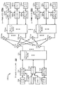
図2は、ワイヤレスシステム100におけるアクセスポイント110ならびに2つのユーザ端末120mおよび120xのブロック図を示す。アクセスポイント110は、Nap個のアンテナ224a〜224apを備える。ユーザ端末120mは、Nut,m個のアンテナ252ma〜252muを備え、ユーザ端末120xは、Nut,x個のアンテナ252xa〜252xuを備える。アクセスポイント110は、ダウンリンクでは送信エンティティであり、アップリンクでは受信エンティティである。各ユーザ端末120は、アップリンクでは送信エンティティであり、ダウンリンクでは受信エンティティである。本明細書で使用する「送信エンティティ」は、周波数チャネルを介してデータを送信することが可能な独立動作型の装置またはデバイスであり、「受信エンティティ」は、周波数チャネルを介してデータを受信することが可能な独立動作型の装置またはデバイスである。以下の説明では、下付き文字「dn」はダウンリンクを示し、下付き文字「up」はアップリンクを示し、Nup個のユーザ端末がアップリンク上での同時送信のために選択され、Ndn個のユーザ端末がダウンリンク上での同時送信のために選択され、Nupは、Ndnに等しいことも等しくないこともあり、NupおよびNdnは、静的な値であってもよく、またはスケジュール間隔ごとに変化することができる。アクセスポイントおよびユーザ端末において、ビームステアリングまたは何らかの他の空間処理技法が使用され得る。
FIG. 2 shows a block diagram of an
アップリンク上では、アップリンク送信のために選択された各ユーザ端末120において、TXデータプロセッサ288は、データソース286からトラフィックデータを受信し、コントローラ280から制御データを受信する。TXデータプロセッサ288は、ユーザ端末のための選択されたレートに関連付けられたコーディングおよび変調方式に基づいて、ユーザ端末のためのトラフィックデータ{dup,m}を処理(たとえば、符号化、インターリーブ、および変調)し、Nut,m個のアンテナのうちの1つについてデータシンボルストリーム{sup,m}を与える。トランシーバフロントエンド(TMTR)254は、アップリンク信号を生成するために、それぞれのシンボルストリームを受信し、処理(たとえば、アナログ変換、増幅、フィルタリング、および周波数アップコンバート)する。トランシーバフロントエンド254は、たとえば、RFスイッチを介した送信ダイバーシティのために、Nut,m個のアンテナのうちの1つにアップリンク信号をルーティングすることもできる。コントローラ280は、トランシーバフロントエンド254内のルーティングを制御することができる。
On the uplink, at each
アップリンク上での同時伝送のためにNup個のユーザ端末がスケジュールできる。これらのユーザ端末の各々は、アップリンク上で処理されたシンボルストリームのそのセットをアクセスポイントに送信する。 N up user terminals can be scheduled for simultaneous transmission on the uplink. Each of these user terminals transmits its set of processed symbol streams on the uplink to the access point.
アクセスポイント110において、Nap個のアンテナ224a〜224apは、アップリンク上で送信を行うすべてのNup個のユーザ端末からアップリンク信号を受信する。受信ダイバーシティでは、トランシーバフロントエンド222は、処理のためにアンテナ224のうちの1つから受信された信号を選択することができる。本開示のいくつかの態様では、複数のアンテナ224から受信された信号の組合せは、強化された受信ダイバーシティのために結合され得る。アクセスポイントのトランシーバフロントエンド222はまた、ユーザ端末のトランシーバフロントエンド254によって実行されるものを補足する処理を実行し、復元されたアップリンクデータシンボルストリームを提供する。復元されたアップリンクデータシンボルストリームは、ユーザ端末によって送信されたデータシンボルストリーム{sup,m}の推定値である。RXデータプロセッサ242は、そのストリームのために使用されたレートに従って復元されたアップリンクデータシンボルストリームを処理(たとえば、復調、デインターリーブ、および復号)して、復号データを得る。各ユーザ端末の復号データは、記憶のためにデータシンク244に与えられてよく、かつ/または、さらなる処理のためにコントローラ230に与えられてよい。
At
ダウンリンク上では、アクセスポイント110において、TXデータプロセッサ210は、ダウンリンク送信のためにスケジュールされたNdn個のユーザ端末のためのデータソース208からトラフィックデータを受信し、コントローラ230から制御データを受信し、場合によってはスケジューラ234から他のデータを受信する。様々なタイプのデータが、様々なトランスポートチャネル上で送信され得る。TXデータプロセッサ210は、そのユーザ端末のために選択されたレートに基づいて、各ユーザ端末のトラフィックデータを処理(たとえば、符号化、インターリーブ、変調)する。TXデータプロセッサ210は、Nap個のアンテナのうちの1つから送信されるNdn個のユーザ端末のうちの1つまたは複数のダウンリンクデータシンボルストリームを提供することができる。トランシーバフロントエンド222は、ダウンリンク信号を生成するために、シンボルストリームを受信し、処理(たとえば、アナログ変換、増幅、フィルタリング、および周波数アップコンバート)する。トランシーバフロントエンド222はまた、たとえば、RFスイッチを介した送信ダイバーシティのために、Nap個のアンテナ224のうちの1つまたは複数にダウンリンク信号をルーティングすることもできる。コントローラ230は、トランシーバフロントエンド222内のルーティングを制御することができる。
On the downlink, at
各ユーザ端末120において、Nut,m個のアンテナ252は、アクセスポイント110からダウンリンク信号を受信する。ユーザ端末120における受信ダイバーシティでは、トランシーバフロントエンド254は、処理のためにアンテナ252のうちの1つから受信される信号を選択することができる。本開示のいくつかの態様では、複数のアンテナ252から受信された信号の組合せは、強化された受信ダイバーシティのために結合され得る。ユーザ端末のトランシーバフロントエンド254はまた、アクセスポイントのトランシーバフロントエンド222によって実行されるものを補足する処理を実行し、復元されたダウンリンクデータシンボルストリームを提供する。RXデータプロセッサ270は、ユーザ端末のための復号データを得るために、復元されたダウンリンクデータシンボルストリームを処理(たとえば、復調、デインターリーブ、および復号)する。
In each
本明細書で説明する技法は、一般に、たとえばSDMA、OFDMA、CDMA、SDMA、およびそれらの組合せなど、任意のタイプの多元接続方式を利用するシステムにおいて適用され得ることを、当業者であれば認識されよう。 Those skilled in the art will recognize that the techniques described herein may generally be applied in systems that utilize any type of multiple access scheme, such as, for example, SDMA, OFDMA, CDMA, SDMA, and combinations thereof. Let's be done.
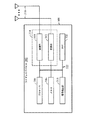
図3は、図1のワイヤレス通信システム1内で利用され得るワイヤレスデバイス302において使用され得る様々な構成要素を示す。ワイヤレスデバイス302は、本明細書で説明する様々な方法を実装するように構成され得るデバイスの一例である。ワイヤレスデバイス302は、図1のアクセスポイント110またはアクセス端末120のうちの任意のものであり得る。
FIG. 3 illustrates various components that may be used in a wireless device 302 that may be utilized within the
ワイヤレスデバイス302は、ワイヤレスデバイス302の動作を制御するプロセッサ304を含み得る。プロセッサ304は中央処理装置(CPU)と呼ばれることもある。読取り専用メモリ(ROM)とランダムアクセスメモリ(RAM)の両方を含み得るメモリ306は、命令とデータとをプロセッサ304に与える。メモリ306の一部分は、不揮発性ランダムアクセスメモリ(NVRAM)も含み得る。プロセッサ304は、一般に、メモリ306内に記憶されたプログラム命令に基づいて論理演算および算術演算を実行する。メモリ306中の命令は、本明細書で説明される方法を実施するように実行可能であり得る。
Wireless device 302 may include a
ワイヤレスデバイス302は、ワイヤレスデバイス302と遠隔地との間のデータの送信および受信を可能にするための送信部310と受信部312とを含み得る、ハウジング308も含み得る。送信部310と受信部312とを組み合わせてトランシーバ314を形成し得る。単一または複数の送信アンテナ316は、ハウジング308に取り付けられ、トランシーバ314に電気的に結合され得る。ワイヤレスデバイス302は、複数の送信部、複数の受信部、複数のトランシーバをも含み得る(図示せず)。
The wireless device 302 may also include a
ワイヤレスデバイス302は、トランシーバ314によって受信された信号のレベルを検出および定量化するために使用され得る信号検出部318も含み得る。信号検出部318は、総エネルギー、シンボルごとのサブキャリア当たりのエネルギー、電力スペクトル密度および他の信号などの信号を検出し得る。ワイヤレスデバイス302は、信号を処理する際に使用するためのデジタル信号プロセッサ(DSP)320も含み得る。
The wireless device 302 may also include a
ワイヤレスデバイス302の様々な構成要素は、データバスに加えて、電力バスと、制御信号バスと、ステータス信号バスとを含み得るバスシステム322によって互いに結合され得る。
The various components of the wireless device 302 may be coupled together by a
本開示のいくつかの態様では、論理ワイヤレス通信チャネルは、制御チャネルとトラフィックチャネルとに分類され得る。論理制御チャネルは、システム制御情報をブロードキャストするためのダウンリンク(DL)チャネルであるブロードキャスト制御チャネル(BCCH)を含み得る。ページング制御チャネル(PCCH)は、ページング情報を転送するDL論理制御チャネルである。マルチキャスト制御チャネル(MCCH)は、1つまたは複数のマルチキャストトラフィックチャネル(MTCH)についてのマルチメディアブロードキャストおよびマルチキャストサービス(MBMS)のスケジューリングおよび制御情報を送信するために使用されるポイントツーマルチポイントDL論理制御チャネルである。概して、無線リソース制御(RRC)接続を確立した後、MCCHは、MBMSを受信するユーザ端末によって使用されるだけであり得る。専用制御チャネル(DCCH)は、専用制御情報を送信するポイントツーポイント双方向論理制御チャネルであり、RRC接続を有するユーザ端末によって使用される。論理トラフィックチャネルは、ユーザ情報を転送するための1つのユーザ端末に専用のポイントツーポイント双方向チャネルである専用トラフィックチャネル(DTCH)を含み得る。さらに、論理トラフィックチャネルは、トラフィックデータを送信するためのポイントツーマルチポイントDLチャネルであるマルチキャストトラフィックチャネル(MTCH)を含み得る。 In some aspects of the present disclosure, logical wireless communication channels may be classified into control channels and traffic channels. The logical control channel may include a broadcast control channel (BCCH), which is a downlink (DL) channel for broadcasting system control information. The paging control channel (PCCH) is a DL logical control channel that transfers paging information. Multicast Control Channel (MCCH) is a point-to-multipoint DL logical control used to transmit multimedia broadcast and multicast service (MBMS) scheduling and control information for one or more multicast traffic channels (MTCH) Is a channel. In general, after establishing a radio resource control (RRC) connection, the MCCH may only be used by user terminals that receive MBMS. The dedicated control channel (DCCH) is a point-to-point bidirectional logical control channel that transmits dedicated control information, and is used by user terminals having an RRC connection. The logical traffic channel may include a dedicated traffic channel (DTCH), which is a point-to-point bi-directional channel dedicated to one user terminal for transferring user information. Further, the logical traffic channel may include a multicast traffic channel (MTCH), which is a point-to-multipoint DL channel for transmitting traffic data.
トランスポートチャネルは、DLチャネルとULチャネルとに分類され得る。DLトランスポートチャネルは、ブロードキャストチャネル(BCH)、ダウンリンク共有データチャネル(DL-SDCH)、およびページングチャネル(PCH)を含み得る。PCHは、ユーザ端末において節電をサポートするために利用され(すなわち、間欠受信(DRX)サイクルがネットワークによってユーザ端末に示されることが可能であり)、セル全体にわたってブロードキャストされ、他の制御/トラフィックチャネルのために使用され得る物理レイヤ(PHY)リソースにマッピングされ得る。ULトランスポートチャネルは、ランダムアクセスチャネル(RACH)、要求チャネル(REQCH)、アップリンク共有データチャネル(UL-SDCH)、および複数のPHYチャネルを含み得る。 Transport channels can be classified into DL channels and UL channels. DL transport channels may include a broadcast channel (BCH), a downlink shared data channel (DL-SDCH), and a paging channel (PCH). PCH is used to support power saving at the user terminal (i.e., a discontinuous reception (DRX) cycle can be indicated to the user terminal by the network), broadcast throughout the cell, and other control / traffic channels Can be mapped to physical layer (PHY) resources that can be used for The UL transport channel may include a random access channel (RACH), a request channel (REQCH), an uplink shared data channel (UL-SDCH), and multiple PHY channels.
PHYチャネルは、DLチャネルとULチャネルとのセットを含み得る。DL PHYチャネルは、共通パイロットチャネル(CPICH)、同期チャネル(SCH)、共通制御チャネル(CCCH)、共有DL制御チャネル(SDCCH)、マルチキャスト制御チャネル(MCCH)、共有UL割当てチャネル(SUACH)、肯定応答チャネル(ACKCH)、DL物理共有データチャネル(DL-PSDCH)、UL電力制御チャネル(UPCCH)、ページングインジケータチャネル(PICH)、および負荷インジケータチャネル(LICH)を含み得る。UL PHYチャネルは、物理ランダムアクセスチャネル(PRACH)、チャネル品質インジケータチャネル(CQICH)、肯定応答チャネル(ACKCH)、アンテナサブセットインジケータチャネル(ASICH)、共有要求チャネル(SREQCH)、UL物理共有データチャネル(UL-PSDCH)、およびブロードバンドパイロットチャネル(BPICH)を含み得る。 The PHY channel may include a set of DL channels and UL channels. DL PHY channel includes common pilot channel (CPICH), synchronization channel (SCH), common control channel (CCCH), shared DL control channel (SDCCH), multicast control channel (MCCH), shared UL allocated channel (SUACH), acknowledgment A channel (ACKCH), a DL physical shared data channel (DL-PSDCH), a UL power control channel (UPCCH), a paging indicator channel (PICH), and a load indicator channel (LICH) may be included. The UL PHY channel includes physical random access channel (PRACH), channel quality indicator channel (CQICH), acknowledgment channel (ACKCH), antenna subset indicator channel (ASICH), shared request channel (SREQCH), UL physical shared data channel (UL -PSDCH), and broadband pilot channel (BPICH).
ある実施形態では、シングルキャリア波形のPAPR特性を低いまま保つ(任意の所与の時間において、チャネルが周波数に関して連続するまたは均一に離間される)、チャネル構造が提供される。 In certain embodiments, a channel structure is provided that keeps the PAPR characteristics of a single carrier waveform low (channels are continuous or evenly spaced in frequency at any given time).
異なる送信機(たとえば、基地局)から送信されるOFDM信号の周波数領域の直交性は、受信機(たとえば、移動局)における時間同期に依存し得る。送信されたOFDM信号のうちの2つの間で相殺される時間がサイクリックプレフィックス(CP)よりも大きい場合、これらのOFDM信号間の周波数領域の直交性は失われ得る。直交性の損失は、マルチパスのシナリオでは、さらに悪くなり得る。 The frequency domain orthogonality of OFDM signals transmitted from different transmitters (eg, base stations) may depend on time synchronization at the receiver (eg, mobile station). If the time offset between two of the transmitted OFDM signals is greater than the cyclic prefix (CP), the frequency domain orthogonality between these OFDM signals may be lost. The loss of orthogonality can be worse in multipath scenarios.
《例示的なパワーアウェア受信ダイバーシティ制御》
ワイヤレスネットワークでは、ユーザ機器(UE)は、専用モードでなく接続モードであり得る。たとえば、順方向アクセスチャネル(FACH)モードでは、UEは、ワイヤレスネットワークとの専用の接続を有していない場合がある。UEが接続モードである間、UEは、限られた量のデータのみを受信することができる。この段階の間、UE側の電力を節約するために、(たとえば、単一の信号経路に複数の受信チェーン/アンテナ(multiple receive chains/antennas)を使用する)受信ダイバーシティ構成は、使用可能にされない場合がある。さらに、UEによって有限のデータが受信される性質のため、受信ダイバーシティのために達成される信号対雑音比(SNR)の増加は、注目に値する量ではない可能性がある。しかしながら、限界の信号状態および劣った無線環境で、UEによって有限のデータが受信されることとは無関係に、UE側のダウンリンク性能(特にシグナリング手順)は、受信ダイバーシティを使用可能にすることによって強化され得る。しかしながら、受信ダイバーシティは、限界の信号状態におけるUE端での信号対雑音比(SNR)を向上させることはできるが、UEは、消費電力におけるペナルティを負うこともある。
<Example power-aware receive diversity control>
In a wireless network, user equipment (UE) may be in connected mode rather than dedicated mode. For example, in the forward access channel (FACH) mode, the UE may not have a dedicated connection with the wireless network. While the UE is in connected mode, the UE can receive only a limited amount of data. During this phase, receive diversity configurations (eg, using multiple receive chains / antennas for a single signal path) are not enabled to conserve UE side power. There is a case. Further, due to the nature of finite data being received by the UE, the increase in signal to noise ratio (SNR) achieved for receive diversity may not be a noticeable amount. However, regardless of the limited signal conditions and poor radio environment, the UE side downlink performance (especially the signaling procedure) can be achieved by enabling receive diversity, regardless of the finite data received by the UE. Can be strengthened. However, although receive diversity can improve the signal-to-noise ratio (SNR) at the UE end in marginal signal conditions, the UE may incur a penalty in power consumption.
限界の信号状態および劣った無線環境では、上記のように、非専用モードのUEは、劣ったシグナリング手順性能を経験し得る。これは、無線リンク制御(RLC)復元不能エラーまたはランダムアクセスチャネル(RACH)メッセージ送信障害をもたらし得、したがって、頻繁なセル再選択およびセル更新手順をもたらし得る。たとえば、UEによって開始される頻繁なセル更新および他の手順のために、UEからのより大きいトラフィックを有するワイヤレスネットワークでは、シグナリング負荷の増加が起こり得る。さらに、物理的なRACH(PRACH)のような共通のリソースの使用の増加およびシステムによって経験される関連の干渉が起こり得る。別の例として、頻繁なセル再選択のために、UE側の電力ドローの増加が起こり得る。 In marginal signal conditions and inferior radio environments, as described above, a UE in non-dedicated mode may experience poor signaling procedure performance. This can result in radio link control (RLC) unrecoverable errors or random access channel (RACH) message transmission failures, and thus can lead to frequent cell reselection and cell update procedures. For example, due to frequent cell updates and other procedures initiated by the UE, an increase in signaling load may occur in a wireless network with greater traffic from the UE. Furthermore, increased use of common resources such as physical RACH (PRACH) and related interference experienced by the system can occur. As another example, an increase in UE side power draw may occur due to frequent cell reselection.
本開示のいくつかの態様は、第2の受信チェーンの使用による消費電力の増加を最低限に保ちながら(または、第2の受信チェーンにより増加した消費電力を少なくとも低減しながら)、ダウンリンク手順性能を向上させるために、(たとえば、UE側の)デュアルアンテナ機構の受信ダイバーシティを動的に制御するための技法を提供する。言い換えれば、受信ダイバーシティを動的に制御することは、消費電力を最低限に保ちながら、ネットワークによって送られるダウンリンクデータを復号する際のより大きい信頼性を達成することができる。デュアルアンテナ機構の動的な制御についてさらに説明するが、本開示の態様は、複数のアンテナを有するワイヤレスデバイスにも適用され得る。 Some aspects of the present disclosure provide for downlink procedures while minimizing the increase in power consumption due to the use of the second receive chain (or at least reducing the increased power consumption due to the second receive chain). To improve performance, a technique is provided for dynamically controlling the receive diversity of a dual antenna mechanism (eg, on the UE side). In other words, dynamically controlling receive diversity can achieve greater reliability in decoding downlink data sent by the network while keeping power consumption to a minimum. Although the dynamic control of the dual antenna mechanism is further described, aspects of the present disclosure may also be applied to wireless devices having multiple antennas.
図4は、本開示のいくつかの態様による、受信ダイバーシティを動的に制御するための例示的動作400を示す。動作400は、たとえば、UEによって実行され得る。402で、UEは、第1の受信チェーンで、ダウンリンク送信中に第2の受信チェーンを使用可能にするためのトリガイベントを検出することができる。たとえば、UEトリガ機構は、動的な方法で受信ダイバーシティ(RxD)を使用可能および使用不能にすることができる。404で、UEは、トリガイベントに基づいて第2の受信チェーンを使用可能にすることができる(たとえば、UEが信号の2つのストリームを受信することができる別の信号経路)。406で、UEは、持続時間後、第2の受信チェーンの少なくとも一部を使用不能にすることができる。
FIG. 4 illustrates an
いくつかの態様では、トリガイベントは、ダウンリンク送信をもたらす無線リソース制御(RRC)シグナリング手順に基づき得、RRCシグナリング手順の持続時間は、既知であり得る。RRCシグナリング手順の開始時に、RRCは、開始された手順の結果、UEがダウンリンク上でデータを受信することになるかどうかを認識し得る。さらに、RRCは、UEがデータを受信すると予想される時間枠についての知識を有し得る。RRCは、したがって、ネットワークによって送られるデータを確実に復号するために、RxDが使用可能にされる持続時間を示すことができる。所定の持続時間が時間切れになると、消費電力を最低限に抑えるために、RxDの少なくとも一部は、使用不能にされ得る。 In some aspects, the trigger event may be based on a radio resource control (RRC) signaling procedure that results in a downlink transmission, and the duration of the RRC signaling procedure may be known. At the start of the RRC signaling procedure, the RRC may recognize whether the initiated procedure will result in the UE receiving data on the downlink. Further, the RRC may have knowledge about the time frame in which the UE is expected to receive data. The RRC can thus indicate the duration that RxD is enabled to reliably decode the data sent by the network. When the predetermined duration expires, at least a portion of RxD can be disabled to minimize power consumption.
いくつかの態様では、トリガイベントは、無線リンク規制(RLC)データアクティビティに基づき得る。(たとえば、パケットデータコンバージェンスプロトコル(PDCP)/DSのようなデータ経路上で)RLCレベルからのデータプロトコルデータユニット(PDU)の送信の開始時に、RLCは、(たとえば、承認されたモード(AM)PDUについてのUEから送信されるステータスPDUなど)アップリンク送信の予想される応答時間を認識し得る。したがって、RLCは、RxDが使用可能にされ得る持続時間を示すことができる。たとえば、RxDは、RLCレベルからのデータPDUの送信の開始時に、第2の受信チェーンを使用可能にすることができ、UEからのアップリンク送信のための予想される応答時間時またはその前に、第2の受信チェーンの少なくとも一部を使用不能にすることができる。 In some aspects, the trigger event may be based on radio link regulation (RLC) data activity. At the start of transmission of a data protocol data unit (PDU) from the RLC level (e.g., on a data path such as packet data convergence protocol (PDCP) / DS), the RLC (e.g., approved mode (AM) The expected response time for uplink transmission (such as a status PDU sent from the UE for the PDU) may be recognized. Thus, the RLC can indicate the duration that RxD can be enabled. For example, the RxD may enable the second receive chain at the start of transmission of data PDUs from the RLC level, at or before the expected response time for uplink transmission from the UE. , At least a portion of the second receive chain can be disabled.
図5Aは、本開示のいくつかの態様による、ダウンリンク送信中の所定の持続時間の間、UEの第2の受信チェーンを使用可能にするためのタイムラインを示す。502で、UEは、第1の受信チェーンで、ダウンリンク送信中に第2の受信チェーンを使用可能にするためのトリガイベントを検出することができる。上記のように、第2の受信チェーンを使用可能にするための所定の持続時間504は、RRCシグナリング手順またはRLCデータアクティビティによって示され得る。持続時間504が終了すると、第2の受信チェーンは、使用不能にされ得る。
FIG. 5A shows a timeline for enabling a second receive chain of a UE for a predetermined duration during downlink transmission according to some aspects of the present disclosure. At 502, the UE can detect a trigger event to enable the second receive chain during downlink transmission in the first receive chain. As described above, the
UEが接続モードであるとき、UEによって受信されるデータは、2次共通制御物理チャネル(SCCPCH)上で送られ得る。使用されるSCCPCHスロットフォーマットは、トランスポートフォーマット結合インジケータ(TFCI)の固定位置およびパイロットビットを有し得る。いくつかの態様では、トリガイベントを検出することは、一般に、(たとえば、スロットごとに蓄積された)TFCIビットに対応するシンボルのエネルギーを閾値と比較し、シンボルのエネルギーが閾値を超えると、トリガイベントを検出することを含む。ネットワークが間欠的にダウンリンクデータをスケジュールするとき、TFCI/パイロットビットに対応する復調されたシンボルのエネルギーは、発見的に到達する閾値と比較され、したがって、SCCPCHにおけるデータからのダウンリンク送信が検出され、RxDが使用可能にされ得る。いくつかの態様では、閾値は、一般に、シンボルの(たとえば、1つのスロットおよびいくつかのスロットにわたる蓄積されたシンボルの)絶対的なエネルギーメトリックを含む。少なくとも第2の受信チェーンを使用不能にすることは、一般に、シンボルのエネルギーが閾値をもはや超えないことをさらに検出することを含む。 When the UE is in connected mode, data received by the UE may be sent on the secondary common control physical channel (SCCPCH). The SCCPCH slot format used may have a transport format combination indicator (TFCI) fixed position and pilot bits. In some aspects, detecting a trigger event generally compares the energy of a symbol corresponding to a TFCI bit (e.g., accumulated per slot) with a threshold and triggers when the energy of the symbol exceeds the threshold. Includes detecting events. When the network intermittently schedules downlink data, the energy of the demodulated symbol corresponding to the TFCI / pilot bit is compared to a heuristically reached threshold, thus detecting downlink transmission from data on SCCPCH And RxD can be enabled. In some aspects, the threshold generally includes an absolute energy metric of symbols (eg, accumulated symbols across one slot and several slots). Disabling at least the second receive chain generally includes further detecting that the energy of the symbol no longer exceeds the threshold.
図5Bは、本開示のいくつかの態様による、ダウンリンク送信中にUEの第2の受信チェーンを使用可能および使用不能にするためのタイムラインを示す。上記で説明したように、UEは、シンボルのエネルギーを閾値と比較し、(506で)シンボルのエネルギーが閾値を超えると、トリガイベントを検出することができ、これは、場合によっては、ダウンリンク送信の検出を示す。その後、ダウンリンク送信の間、第2の受信が使用可能にされ得る。ある時間期間の後、(508で)シンボルのエネルギーが閾値をもはや超えないことをUEが検出することができ、これは、場合によっては、ダウンリンク送信の終わりを示す。その結果、第2の受信チェーンは、使用不能にされ得る。 FIG. 5B shows a timeline for enabling and disabling a UE's second receive chain during downlink transmission according to some aspects of the present disclosure. As explained above, the UE may compare the symbol energy to a threshold and detect (at 506) a trigger event when the symbol energy exceeds the threshold, which in some cases may be downlinked. Indicates detection of transmission. Thereafter, a second reception may be enabled during downlink transmission. After a certain period of time, the UE can detect (at 508) that the energy of the symbol no longer exceeds the threshold, which in some cases indicates the end of the downlink transmission. As a result, the second receive chain can be disabled.
第2の受信チェーン(すなわち、ダイバーシティアンテナ)を使用可能および使用不能にすることは、一般に、多数の構成要素を伴い、動的なトグルが使用可能にされる場合、レイテンシをもたらし得る。たとえば、信号の受信のために第2の受信チェーンを使用可能にすることは、一般に、各々が終了するのに有限の時間量がかかるいくつかのステップを含む。本開示の態様は、第2の受信チェーンを使用可能/使用不能にするための処理オーバーヘッドを最低限に抑えるための技法を提供する。 Enabling and disabling the second receive chain (ie, diversity antenna) generally involves multiple components and can result in latency when dynamic toggles are enabled. For example, enabling a second receive chain for signal reception generally involves several steps that each take a finite amount of time to complete. Aspects of this disclosure provide techniques for minimizing processing overhead to enable / disable the second receive chain.
いくつかの態様では、レイテンシは、RxDを低電力モードに保つことによって克服され得る。たとえば、第2の受信チェーンを構成すると、第2の受信チェーンを駆動する位相ロックループ(PLL)はオフにされ得る。言い換えると、トリガイベントを検出すると、第2の受信チェーンの少なくとも一部を使用可能および使用不能にすることは、一般に、第2の受信チェーンのPLL(たとえば、ソースクロックなど)をトグルすることを含む。たとえば、第2の受信チェーンの少なくとも一部を使用不能にすることは、一般に、低電力モードを使用可能にすることを含み、第2の受信チェーンのソースクロックは、使用不能にされる。いくつかの態様では、低電力モードは、ハードウェアおよびソフトウェア/ファームウェアにおけるすべてのステートマシンになされるすべての構成が節約されることを示す。しかしながら、データ受信のためにハードウェアを駆動するソースクロックは、オフにされる。したがって、第2のチェーンは、短い時間のスパンで、ダウンリンク経路において、第1の受信チェーンでのシンボルの増強のために使用可能にされ得る。 In some aspects, latency can be overcome by keeping RxD in a low power mode. For example, when configuring the second receive chain, the phase locked loop (PLL) that drives the second receive chain may be turned off. In other words, upon detecting a trigger event, enabling and disabling at least a portion of the second receive chain generally means toggling the second receive chain's PLL (e.g., source clock, etc.). Including. For example, disabling at least a portion of the second receive chain generally includes enabling a low power mode, and the source clock of the second receive chain is disabled. In some aspects, the low power mode indicates that all configuration done to all state machines in hardware and software / firmware is saved. However, the source clock that drives the hardware for data reception is turned off. Thus, the second chain may be enabled for symbol enhancement in the first receive chain in the downlink path in a short time span.
本開示のいくつかの態様は、RxDを使用するデュアルアンテナ機構を有する受信機のフロントで改良されたDL SIR/SINRを提供する。これによって、第2の受信チェーンの動的なトグルによる消費電力の最低限の増加で、UE側での改良されたダウンリンク性能がもたらされる。したがって、改良されたダウンリンク性能は、UEでの電力要件を低減することができる。たとえば、改良された獲得指示チャネル(AICH)の復号は、プリアンブルの数を低減し得る。各連続したプリアンブルが電力ランプステップによって送信された電力を増加させ、メッセージ部分の電力要件も増加させ得るので、改良されたAICH性能は、UE側の全体的な電力要件の低減をもたらし得る。 Some aspects of the present disclosure provide improved DL SIR / SINR at the front of a receiver having a dual antenna mechanism using RxD. This results in improved downlink performance on the UE side with minimal increase in power consumption due to dynamic toggle of the second receive chain. Thus, improved downlink performance can reduce power requirements at the UE. For example, improved acquisition indication channel (AICH) decoding may reduce the number of preambles. Improved AICH performance may result in a reduction of the overall power requirement on the UE side, as each successive preamble increases the power transmitted by the power ramp step and may also increase the power requirement of the message portion.
さらに、改良されたダウンリンク性能は、劣った無線状態の間、DLでのRLCレベルの再送信の数を低減させ得、可能なRLCのリセットおよび復元できないエラーを回避する。たとえば、WCDMA(登録商標)で、シグナリング無線ベアラ(SRB)メッセージは、1と設定されたmaxRSTを有することができ、これは、リセットの任意のトリガがRLCの復元できないエラーをもたらし得ることを意味する。改良されたダウンリンク性能は、RLCの復元できないエラーによるセル再選択の必要を不要にすることができ、それによってシグナリング経路への負荷が低減し、システム全体における関連の干渉が低減する。また、非専用モードでの改良されたダウンリンク性能は、高速(HS)-RACHおよびHS-FACHの存在によって不可欠になり得る。 Further, improved downlink performance may reduce the number of RLC level retransmissions in the DL during inferior radio conditions, avoiding possible RLC resets and unrecoverable errors. For example, in WCDMA®, a signaling radio bearer (SRB) message can have a maxRST set to 1, which means that any trigger for reset can result in an RLC irrecoverable error To do. Improved downlink performance can eliminate the need for cell reselection due to RLC irreparable errors, thereby reducing the load on the signaling path and reducing associated interference throughout the system. Also, improved downlink performance in non-dedicated mode may be essential due to the presence of high speed (HS) -RACH and HS-FACH.
上記で説明された動作400は、図4の対応する機能を実行することが可能な任意の好適な構成要素または他の手段によって実行され得る。たとえば、図4に示される動作400は、図4Aに示される構成要素400Aに対応する。図4Aでは、トランシーバ(TX/RX)401Aは、1つまたは複数の受信部アンテナで信号を受信することができる。TX/RX401Aの検出ユニット402Aは、第1の受信チェーンで、ダウンリンク送信中に第2の受信チェーンを使用可能にするためのトリガイベントを検出することができる。使用可能ユニット404Aは、トリガイベントに基づいて、第2の受信チェーンを使用可能にし得る。使用不能ユニット406Aは、持続時間後、第2の受信チェーンの少なくとも一部を使用不能にし得る。
The
上記で説明した方法の様々な動作は、対応する機能を実行することができる任意の好適な手段によって実行され得る。手段は、限定はしないが、回路、特定用途向け集積回路(ASIC)、またはプロセッサを含む、様々なハードウェアおよび/またはソフトウェア構成要素および/またはモジュールを含み得る。 The various operations of the methods described above may be performed by any suitable means that can perform the corresponding function. The means may include various hardware and / or software components and / or modules, including but not limited to circuits, application specific integrated circuits (ASICs), or processors.
開示される処理におけるステップの特定の順序または階層は、例示的な手法の一例であることを理解されたい。設計上の選好に基づいて、本開示の範囲内のままでありながら、処理におけるステップの特定の順序または階層が再構成され得ることを理解されたい。添付の方法クレームは、様々なステップの要素を例示的な順序で提示したものであり、提示された特定の順序または階層に限定されるものではない。 It should be understood that the specific order or hierarchy of steps in the processes disclosed is an example of an exemplary approach. Based on design preferences, it should be understood that a particular order or hierarchy of steps in the process may be reconfigured while remaining within the scope of this disclosure. The accompanying method claims present elements of the various steps in a sample order, and are not limited to the specific order or hierarchy presented.
情報および信号は、様々な異なる技術および技法のいずれかを使用して表され得ることが、当業者には理解されよう。たとえば、上記の説明全体にわたって言及され得るデータ、命令、コマンド、情報、信号、ビット、シンボル、およびチップは、電圧、電流、電磁波、磁界または磁性粒子、光場または光学粒子、あるいはそれらの任意の組合せによって表され得る。 Those of skill in the art will understand that information and signals may be represented using any of a variety of different technologies and techniques. For example, data, instructions, commands, information, signals, bits, symbols, and chips that may be referred to throughout the above description are voltages, currents, electromagnetic waves, magnetic fields or magnetic particles, light fields or optical particles, or any of them Can be represented by a combination.
本明細書で開示した実施形態に関連して説明した様々な例示的な論理ブロック、モジュール、回路、およびアルゴリズムステップは、電子ハードウェア、コンピュータソフトウェア、または両方の組合せとして実装され得ることが、当業者にはさらに諒解されよう。ハードウェアとソフトウェアのこの互換性を明確に示すために、様々な例示的な構成要素、ブロック、モジュール、回路、およびステップを、上記では概してそれらの機能に関して説明した。そのような機能をハードウェアとして実装するか、ソフトウェアとして実装するかは、特定の適用例および全体的なシステムに課される設計制約に依存する。当業者は、説明した機能を特定の適用例ごとに様々な方法で実装し得るが、そのような実装の決定は、本開示の範囲からの逸脱を生じるものと解釈すべきではない。 It will be appreciated that the various exemplary logic blocks, modules, circuits, and algorithm steps described in connection with the embodiments disclosed herein may be implemented as electronic hardware, computer software, or a combination of both. The contractor will further understand. To clearly illustrate this interchangeability of hardware and software, various illustrative components, blocks, modules, circuits, and steps have been described above generally in terms of their functionality. Whether such functionality is implemented as hardware or software depends upon the particular application and design constraints imposed on the overall system. Those skilled in the art may implement the described functionality in a variety of ways for each particular application, but such implementation decisions should not be construed as departing from the scope of the present disclosure.
本明細書で開示された実施形態に関連して説明された様々な例示的な論理ブロック、モジュール、および回路は、汎用プロセッサ、デジタル信号プロセッサ(DSP)、特定用途向け集積回路(ASIC)、フィールドプログラマブルゲートアレイ(FPGA)もしくは他のプログラマブル論理デバイス、個別ゲートもしくはトランジスタ論理、個別ハードウェアコンポーネント、または、本明細書で説明された機能を実行するように設計されたそれらの任意の組合せで、実装または実行され得る。汎用プロセッサはマイクロプロセッサであり得るが、代替として、プロセッサは、任意の従来のプロセッサ、コントローラ、マイクロコントローラ、または状態機械であり得る。プロセッサはまた、コンピューティングデバイスの組合せ、たとえば、DSPとマイクロプロセッサとの組合せ、複数のマイクロプロセッサ、DSPコアと連携する1つまたは複数のマイクロプロセッサ、あるいは任意の他のそのような構成として実装され得る。 Various exemplary logic blocks, modules, and circuits described in connection with the embodiments disclosed herein are general purpose processors, digital signal processors (DSPs), application specific integrated circuits (ASICs), field Implementation in a programmable gate array (FPGA) or other programmable logic device, individual gate or transistor logic, individual hardware components, or any combination thereof designed to perform the functions described herein Or it can be implemented. A general purpose processor may be a microprocessor, but in the alternative, the processor may be any conventional processor, controller, microcontroller, or state machine. A processor may also be implemented as a combination of computing devices, eg, a DSP and microprocessor combination, multiple microprocessors, one or more microprocessors in conjunction with a DSP core, or any other such configuration. obtain.
本明細書で開示する実施形態に関して説明した方法またはアルゴリズムのステップは、直接ハードウェアで具現化されるか、プロセッサによって実行されるソフトウェアモジュールで具現化されるか、またはその2つの組合せで具現化され得る。ソフトウェアモジュールは、RAMメモリ、フラッシュメモリ、ROMメモリ、EPROMメモリ、EEPROMメモリ、レジスタ、ハードディスク、リムーバブルディスク、CD-ROM、または当技術分野で知られている任意の他の形態の記録媒体内に常駐することができる。例示的な記録媒体は、プロセッサが記録媒体から情報を読み取り、記録媒体に情報を書き込むことができるように、プロセッサに結合される。代替として、記録媒体はプロセッサと一体であり得る。プロセッサおよび記録媒体はASIC中に常駐し得る。ASICはユーザ端末中に常駐し得る。代替として、プロセッサおよび記録媒体は、ユーザ端末中に個別構成要素として常駐し得る。 The method or algorithm steps described in connection with the embodiments disclosed herein may be implemented directly in hardware, software modules executed by a processor, or a combination of the two. Can be done. Software modules reside in RAM memory, flash memory, ROM memory, EPROM memory, EEPROM memory, registers, hard disk, removable disk, CD-ROM, or any other form of recording medium known in the art can do. An exemplary recording medium is coupled to the processor such that the processor can read information from, and write information to, the recording medium. In the alternative, the recording medium may be integral to the processor. The processor and recording medium can reside in an ASIC. The ASIC can reside in the user terminal. In the alternative, the processor and the storage medium may reside as discrete components in a user terminal.
1つまたは複数の例示的な実施形態では、説明された機能は、ハードウェア、ソフトウェア、ファームウェア、またはそれらの任意の組合せで実装され得る。ソフトウェアで実装される場合、機能は、1つまたは複数の命令またはコードとしてコンピュータ可読媒体上に記憶されるか、あるいはコンピュータ可読媒体上で符号化され得る。コンピュータ可読媒体は、コンピュータ記録媒体を含む。記録媒体は、コンピュータによってアクセスされ得る任意の利用可能な媒体であり得る。限定ではなく例として、そのようなコンピュータ可読媒体は、RAM、ROM、EEPROM、CD-ROMもしくは他の光ディスクストレージ、磁気ディスクストレージもしくは他の磁気ストレージデバイス、または、命令もしくはデータ構造の形態の所望のプログラムコードを搬送もしくは記憶するために使用でき、コンピュータによってアクセスできる、任意の他の媒体を含み得る。本明細書で使用する場合、ディスク(disk)およびディスク(disc)は、コンパクトディスク(CD)、レーザーディスク(登録商標)、光ディスク、デジタル多用途ディスク(DVD)、フロッピー(登録商標)ディスク、およびブルーレイディスクを含み、ディスク(disk)は、通常、磁気的にデータを再生し、ディスク(disc)は、レーザーで光学的にデータを再生する。上記の組合せもコンピュータ可読媒体の範囲内に含めるべきである。 In one or more exemplary embodiments, the functions described may be implemented in hardware, software, firmware, or any combination thereof. If implemented in software, the functions may be stored on or encoded as one or more instructions or code on a computer-readable medium. Computer-readable media includes computer recording media. A storage media may be any available media that can be accessed by a computer. By way of example, and not limitation, such computer-readable media can be RAM, ROM, EEPROM, CD-ROM or other optical disk storage, magnetic disk storage or other magnetic storage device, or any desired form in the form of instructions or data structures. It can include any other medium that can be used to carry or store program code and that can be accessed by a computer. As used herein, disk and disc are compact disc (CD), laser disc (registered trademark), optical disc, digital versatile disc (DVD), floppy (registered trademark) disc, and Including Blu-ray discs, the disk normally reproduces data magnetically, and the disc optically reproduces data with a laser. Combinations of the above should also be included within the scope of computer-readable media.
本明細書で使用する、項目のリスト「のうちの少なくとも1つ」を指す句は、個々のメンバーを含む、それらの項目の任意の組合せを指す。一例として、「a、b、またはcのうちの少なくとも1つ」は、a、b、c、a-b、a-c、b-c、およびa-b-cをカバーするものとする。 As used herein, a phrase referring to “at least one of” a list of items refers to any combination of those items, including individual members. As an example, “at least one of a, b, or c” shall cover a, b, c, a-b, a-c, b-c, and a-b-c.
開示される実施形態の上記の説明は、当業者が本開示を作成または使用できるようにするために提供される。これらの実施形態への様々な修正が当業者には容易に明らかになり、本明細書で定義される一般的な原理は、本開示の趣旨および範囲を逸脱することなく他の実施形態に適用され得る。したがって、本開示は、本明細書に示される実施形態に限定されるものではなく、本明細書で開示される原理および新規の特徴に一致する最大の範囲を与えられるものである。 The above description of the disclosed embodiments is provided to enable any person skilled in the art to make or use the present disclosure. Various modifications to these embodiments will be readily apparent to those skilled in the art, and the generic principles defined herein may be applied to other embodiments without departing from the spirit and scope of the disclosure. Can be done. Accordingly, the present disclosure is not intended to be limited to the embodiments shown herein but is to be accorded the widest scope consistent with the principles and novel features disclosed herein.
100 ワイヤレス通信システム
110 アクセスポイント
120 ユーザ端末
130 システムコントローラ
208 データソース
210 TXデータプロセッサ
222 トランシーバフロントエンド
224 アンテナ
230 コントローラ
234 スケジューラ
242 RXデータプロセッサ
244 データシンク
252 アンテナ
254 トランシーバフロントエンド
270 RXデータプロセッサ
280 コントローラ
286 データソース
288 TXデータプロセッサ
302 ワイヤレスデバイス
304 プロセッサ
306 メモリ
308 ハウジング
310 送信部
312 受信部
314 トランシーバ
316 送信アンテナ
318 信号検出部
320 デジタル信号プロセッサ(DSP)
322 バスシステム
400A 構成要素
401A トランシーバ(TX/RX)
402A 検出ユニット
404A 使用可能ユニット
406A 使用不能ユニット
504 持続時間
100 wireless communication system
110 access point
120 user terminals
130 System controller
208 data sources
210 TX data processor
222 Transceiver front end
224 antenna
230 Controller
234 Scheduler
242 RX data processor
244 Data Sync
252 antenna
254 transceiver front end
270 RX data processor
280 controller
286 Data Source
288 TX data processor
302 wireless devices
304 processor
306 memory
308 housing
310 Transmitter
312 Receiver
314 transceiver
316 Transmitting antenna
318 Signal detector
320 Digital Signal Processor (DSP)
322 Bus system
400A component
401A transceiver (TX / RX)
402A detection unit
404A usable unit
406A Unusable unit
504 duration
Claims (13)
第1の受信チェーンで、ダウンリンク送信中に第2の受信チェーンを使用可能にするためのトリガイベントを検出するステップであって、前記第1の受信チェーンおよび前記第2の受信チェーンの各々がアンテナを含む、ステップと、
前記トリガイベントに基づいて、前記第2の受信チェーンを使用可能にするステップと、
持続時間後、前記第2の受信チェーンの少なくとも一部を使用不能にするステップであって、前記持続時間は前記トリガイベントによって示され、前記持続時間は、アップリンク送信のための予想される応答時間に基づく、ステップとを含む方法。 A method for wireless communication performed by a user equipment comprising :
Detecting a trigger event for enabling a second receive chain during downlink transmission in the first receive chain, wherein each of the first receive chain and the second receive chain is Including an antenna, a step ;
Enabling the second receive chain based on the trigger event;
After sustained time, a step of disabling at least a portion of said second receive chain, the duration indicated by the trigger event, the duration, the expected for uplink transmission And a step based on response time .
トランスポートフォーマット結合インジケータ(TFCI)ビットに対応するシンボルのエネルギーを閾値と比較するステップと、
前記シンボルの前記エネルギーが前記閾値を超えると、前記トリガイベントを検出するステップとを含む、請求項1に記載の方法。 The step of detecting comprises:
Comparing the energy of a symbol corresponding to a transport format combination indicator (TFCI) bit to a threshold;
The method of claim 1, comprising detecting the trigger event when the energy of the symbol exceeds the threshold.
前記シンボルの前記エネルギーが前記閾値をもはや超えないことをさらに検出するステップと、
前記さらなる検出で、前記第2の受信チェーンのソースクロックを使用不能にするステップとを含む、請求項4に記載の方法。 The step of disabling,
Further detecting that the energy of the symbol no longer exceeds the threshold;
5. The method of claim 4 , comprising disabling a source clock of the second receive chain at the further detection.
第1の受信チェーンで、ダウンリンク送信中に第2の受信チェーンを使用可能にするためのトリガイベントを検出するための手段であって、前記第1の受信チェーンおよび前記第2の受信チェーンの各々がアンテナを含む、手段と、
前記トリガイベントに基づいて、前記第2の受信チェーンを使用可能にするための手段と、
持続時間後、前記第2の受信チェーンの少なくとも一部を使用不能にするための手段であって、前記持続時間は前記トリガイベントによって示され、前記持続時間は、アップリンク送信のための予想される応答時間に基づく、手段とを含む装置。 A device for wireless communication,
Means for detecting a trigger event for enabling a second receive chain during downlink transmission in the first receive chain, the first receive chain and the second receive chain Means, each including an antenna ;
Means for enabling the second receive chain based on the trigger event;
After sustained time, and means for disabling at least part of said second receive chain, the duration indicated by the trigger event, the duration, expectations for uplink transmission Means based on a response time to be transmitted .
トランスポートフォーマット結合インジケータ(TFCI)ビットに対応するシンボルのエネルギーを閾値と比較するための手段と、
前記シンボルの前記エネルギーが前記閾値を超えると、前記トリガイベントを検出するための手段とを含む、請求項7に記載の装置。 Said means for detecting comprises:
Means for comparing the energy of a symbol corresponding to a transport format combination indicator (TFCI) bit with a threshold;
8. The apparatus of claim 7 , comprising: means for detecting the trigger event when the energy of the symbol exceeds the threshold.
前記シンボルの前記エネルギーが前記閾値をもはや超えないことをさらに検出するための手段と、
前記さらなる検出で、前記第2の受信チェーンのソースクロックを使用不能にするための手段とを含む、請求項10に記載の装置。 Said means for disabling,
Means for further detecting that the energy of the symbol no longer exceeds the threshold;
Wherein a further detection, and means for disabling the source Sukurokku of the second receive chain, according to claim 10.
Applications Claiming Priority (5)
| Application Number | Priority Date | Filing Date | Title |
|---|---|---|---|
| US201161581047P | 2011-12-28 | 2011-12-28 | |
| US61/581,047 | 2011-12-28 | ||
| US13/542,288 US9614606B2 (en) | 2011-12-28 | 2012-07-05 | Method and apparatus for power aware receive diversity control |
| US13/542,288 | 2012-07-05 | ||
| PCT/US2012/071056 WO2013101680A1 (en) | 2011-12-28 | 2012-12-20 | Method and apparatus for power aware receive diversity control |
Publications (3)
| Publication Number | Publication Date |
|---|---|
| JP2015506618A JP2015506618A (en) | 2015-03-02 |
| JP2015506618A5 JP2015506618A5 (en) | 2016-01-21 |
| JP6069353B2 true JP6069353B2 (en) | 2017-02-01 |
Family
ID=48694729
Family Applications (1)
| Application Number | Title | Priority Date | Filing Date |
|---|---|---|---|
| JP2014550385A Expired - Fee Related JP6069353B2 (en) | 2011-12-28 | 2012-12-20 | Method and apparatus for power-aware receive diversity control |
Country Status (7)
| Country | Link |
|---|---|
| US (1) | US9614606B2 (en) |
| EP (1) | EP2798751A1 (en) |
| JP (1) | JP6069353B2 (en) |
| KR (1) | KR20140117441A (en) |
| CN (1) | CN104025473B (en) |
| IN (1) | IN2014CN04574A (en) |
| WO (1) | WO2013101680A1 (en) |
Families Citing this family (10)
| Publication number | Priority date | Publication date | Assignee | Title |
|---|---|---|---|---|
| US9591574B2 (en) * | 2012-10-09 | 2017-03-07 | Apple Inc. | Dynamic receive diversity selection for LTE |
| US10165512B2 (en) | 2012-10-09 | 2018-12-25 | Apple Inc. | Dynamic wireless circuitry configuration for carrier aggregation component carriers |
| US9379788B2 (en) * | 2013-02-21 | 2016-06-28 | Intel Mobile Communications GmbH | Communications terminal, and a method for selecting a transmit antenna for a transmission to a radio communications network |
| US9214999B2 (en) * | 2013-07-10 | 2015-12-15 | Qualcomm Incorporated | Apparatus and method for adaptive receive diversity using link quality in wireless communications |
| US9210725B2 (en) * | 2013-08-30 | 2015-12-08 | Qualcomm Incorporated | Method and apparatus for improving uplink performance at a user equipment |
| US20160198411A1 (en) * | 2015-01-06 | 2016-07-07 | Marvell World Trade Ltd. | Network-assisted power consumption reduction in a wireless communication terminal |
| US10045244B2 (en) | 2015-09-03 | 2018-08-07 | Qualcomm Incorporated | Enhanced connection performance in UL/DL imbalance scenarios |
| US10110398B2 (en) | 2016-06-10 | 2018-10-23 | Apple Inc. | Adaptive receive diversity |
| KR102271769B1 (en) | 2017-03-15 | 2021-07-01 | 삼성전자주식회사 | Wireless communication apparatus and method for performing energy-efficient link adaptation |
| CN113543286A (en) * | 2020-04-17 | 2021-10-22 | 华为技术有限公司 | Receiving chain opening state switching method and first multi-link equipment |
Family Cites Families (35)
| Publication number | Priority date | Publication date | Assignee | Title |
|---|---|---|---|---|
| US4866421A (en) * | 1987-06-18 | 1989-09-12 | Texas Instruments Incorporated | Communications circuit having an interface for external address decoding |
| EP0502566A1 (en) | 1991-03-06 | 1992-09-09 | Delco Electronics Corporation | Apparatus for communicating with a vehicle |
| US7024168B1 (en) * | 1999-07-07 | 2006-04-04 | Telefonaktiebolaget L M Ericsson (Publ) | Controlled antenna diversity |
| EP1263179B1 (en) | 2001-05-29 | 2007-06-27 | Lucent Technologies Inc. | Channel estimation for a CDMA system using coded control symbols as additional pilot symbols |
| US7292552B2 (en) * | 2002-03-14 | 2007-11-06 | Qualcomm Incorporated | Method and apparatus for reducing interference in a wireless communication system |
| US20030235252A1 (en) * | 2002-06-19 | 2003-12-25 | Jose Tellado | Method and system of biasing a timing phase estimate of data segments of a received signal |
| US7929921B2 (en) * | 2003-06-10 | 2011-04-19 | Motorola Mobility, Inc. | Diversity control in wireless communications devices and methods |
| US7539507B2 (en) * | 2003-11-21 | 2009-05-26 | Qualcomm Incorporated | Peer-to-peer communications |
| UA91017C2 (en) | 2004-03-05 | 2010-06-25 | Квелкомм Инкорпорейтед | Method and device for control of diversity reception in a wireless communication system |
| KR20050118591A (en) | 2004-06-14 | 2005-12-19 | 엘지전자 주식회사 | Method for handling radio link control date in mobile communication system |
| US7463704B1 (en) * | 2004-07-01 | 2008-12-09 | Atheros Communications, Inc. | Multi-chain signal detection and gain control for automatic gain control systems |
| JP4490781B2 (en) * | 2004-10-18 | 2010-06-30 | 株式会社東芝 | Wireless communication apparatus and wireless communication system |
| US7848305B2 (en) * | 2005-02-03 | 2010-12-07 | Qualcomm Incorporated | Techniques for accessing a wireless communication system with tune-away capability |
| JP2006246364A (en) | 2005-03-07 | 2006-09-14 | Sanyo Electric Co Ltd | Diversity receiver |
| JP2007158515A (en) | 2005-12-01 | 2007-06-21 | Matsushita Electric Ind Co Ltd | Diversity receiver |
| CN101411078A (en) | 2006-03-29 | 2009-04-15 | 日本电气株式会社 | Transmitter-receiver and operation control method thereof |
| US7711341B2 (en) * | 2006-05-31 | 2010-05-04 | Spreadtrum Communications Inc. | Multimode receiver control method and apparatus |
| US20080080434A1 (en) * | 2006-09-28 | 2008-04-03 | Guy Wolf | Method and apparatus of system scheduler |
| US8594171B2 (en) | 2006-12-14 | 2013-11-26 | Qualcomm Incorporated | Method and apparatus for operating a diversity receiver with an equalizer and a rake receiver |
| US20080151871A1 (en) | 2006-12-22 | 2008-06-26 | Nokia Corporation | Power-Efficient Multi-Branch Reception |
| ATE509497T1 (en) * | 2007-03-14 | 2011-05-15 | Magnolia Broadband Inc | METHOD, APPARATUS AND SYSTEM FOR PROVIDING TRANSMISSION DIVERSITY FEEDBACK |
| JP4783402B2 (en) | 2007-06-13 | 2011-09-28 | イノヴァティヴ ソニック リミテッド | Method and apparatus for improving HARQ function in a wireless communication system |
| CN103490853B (en) * | 2007-09-28 | 2017-06-27 | 交互数字专利控股公司 | A kind of method and wireless transmitter/receiver unit for producing and transmitting RLC PDU |
| KR101595671B1 (en) * | 2008-02-01 | 2016-02-18 | 인터디지탈 패튼 홀딩스, 인크 | Method and apparatus for serving high speed downlink shared channel cell change |
| US20090325501A1 (en) * | 2008-04-24 | 2009-12-31 | Interdigital Patent Holdings, Inc. | Method and apparatus for prioritizing and reporting multiple wireless communication measurement events |
| US20100273517A1 (en) * | 2008-10-24 | 2010-10-28 | Interdigital Patent Holdings, Inc. | Method and apparatus for component temperature control based on reduction of data rate and wtru transmit power |
| CN101741440B (en) * | 2008-11-27 | 2015-09-02 | 三星电子株式会社 | Diversity indicating method in GERAN/MUROS system |
| US8483632B2 (en) * | 2009-11-13 | 2013-07-09 | Motorola Mobility Llc | Radiated power control systems and methods in wireless communication devices |
| US10198062B2 (en) | 2009-11-20 | 2019-02-05 | Nxp B.V. | Microprocessor to resume clocking and execution based on external input pattern detection |
| US8996649B2 (en) * | 2010-02-05 | 2015-03-31 | Qualcomm Incorporated | Utilizing policies for offload and flow mobility in wireless communications |
| EP2369758A1 (en) | 2010-03-19 | 2011-09-28 | Telefonaktiebolaget L M Ericsson (Publ) | Control of multiple receive and transmit paths |
| US8488484B2 (en) | 2010-09-23 | 2013-07-16 | Intel Corporation | Power saving system, method and apparatus for a wireless device |
| KR101175246B1 (en) * | 2011-01-28 | 2012-08-21 | 에스케이하이닉스 주식회사 | Delay Locked Loop |
| US8750187B2 (en) | 2011-05-13 | 2014-06-10 | Qualcomm Incorporated | Data driven adaptive receive chain diversity processing |
| US9001693B2 (en) * | 2011-06-13 | 2015-04-07 | Qualcomm, Incorporated | Enhanced discovery procedures in peer-to-peer wireless local area networks (WLANs) |
-
2012
- 2012-07-05 US US13/542,288 patent/US9614606B2/en not_active Expired - Fee Related
- 2012-12-20 IN IN4574CHN2014 patent/IN2014CN04574A/en unknown
- 2012-12-20 WO PCT/US2012/071056 patent/WO2013101680A1/en active Application Filing
- 2012-12-20 JP JP2014550385A patent/JP6069353B2/en not_active Expired - Fee Related
- 2012-12-20 CN CN201280064595.6A patent/CN104025473B/en not_active Expired - Fee Related
- 2012-12-20 EP EP12813679.3A patent/EP2798751A1/en not_active Ceased
- 2012-12-20 KR KR1020147020882A patent/KR20140117441A/en not_active Application Discontinuation
Also Published As
| Publication number | Publication date |
|---|---|
| CN104025473A (en) | 2014-09-03 |
| KR20140117441A (en) | 2014-10-07 |
| IN2014CN04574A (en) | 2015-09-18 |
| WO2013101680A1 (en) | 2013-07-04 |
| US20130170416A1 (en) | 2013-07-04 |
| JP2015506618A (en) | 2015-03-02 |
| CN104025473B (en) | 2019-05-17 |
| US9614606B2 (en) | 2017-04-04 |
| EP2798751A1 (en) | 2014-11-05 |
Similar Documents
| Publication | Publication Date | Title |
|---|---|---|
| JP6069353B2 (en) | Method and apparatus for power-aware receive diversity control | |
| US11558824B2 (en) | Uplink multi-power amplifier/antenna operation and channel prioritization | |
| JP6017438B2 (en) | Power-optimized demodulator front-end (DEMFRONT) receiver subsystem | |
| US9161371B2 (en) | Power optimization using scheduling request delay | |
| JP5815865B2 (en) | Method and apparatus for overload mitigation using uplink transmit power backoff | |
| US9408232B2 (en) | Method and apparatus for contention-based wireless transmissions | |
| EP2428094B1 (en) | System, methods and apparatuses for facilitating discontinuous reception in a multi-carrier wireless communication system | |
| CA2608112C (en) | Data transmission with efficient slot and block formats in a wireless communication system | |
| US8521237B2 (en) | Power saving by limiting use of advanced signal processing | |
| US20110292917A1 (en) | System and method for timing adjustment to protect cqi | |
| US8848742B2 (en) | Transmission strategy in MBSFN subframes | |
| JP6280245B2 (en) | Adaptive control of RF low power mode in multirate wireless system using MCS value | |
| KR20130140863A (en) | Dynamic receive diversity switching | |
| JP6058702B2 (en) | Method and system for early termination of transmission in response to early decoding ACK | |
| JP2012500562A (en) | Multiframe offset between neighboring cells to improve GERAN signaling performance when signaling power control is in use | |
| US8693305B2 (en) | Method and apparatus for detecting OFDM signals in the presence of frequency orthogonal OFDM interferers | |
| JP2015516712A (en) | Ack channel design for early termination of R99 downlink traffic |
Legal Events
| Date | Code | Title | Description |
|---|---|---|---|
| A521 | Written amendment |
Free format text: JAPANESE INTERMEDIATE CODE: A523 Effective date: 20151125 |
|
| A621 | Written request for application examination |
Free format text: JAPANESE INTERMEDIATE CODE: A621 Effective date: 20151125 |
|
| A977 | Report on retrieval |
Free format text: JAPANESE INTERMEDIATE CODE: A971007 Effective date: 20160615 |
|
| A131 | Notification of reasons for refusal |
Free format text: JAPANESE INTERMEDIATE CODE: A131 Effective date: 20160627 |
|
| A521 | Written amendment |
Free format text: JAPANESE INTERMEDIATE CODE: A523 Effective date: 20160926 |
|
| TRDD | Decision of grant or rejection written | ||
| A01 | Written decision to grant a patent or to grant a registration (utility model) |
Free format text: JAPANESE INTERMEDIATE CODE: A01 Effective date: 20161205 |
|
| A61 | First payment of annual fees (during grant procedure) |
Free format text: JAPANESE INTERMEDIATE CODE: A61 Effective date: 20161226 |
|
| R150 | Certificate of patent or registration of utility model |
Ref document number: 6069353 Country of ref document: JP Free format text: JAPANESE INTERMEDIATE CODE: R150 |
|
| R250 | Receipt of annual fees |
Free format text: JAPANESE INTERMEDIATE CODE: R250 |
|
| LAPS | Cancellation because of no payment of annual fees |