JP6069348B2 - Embolization removal cage - Google Patents
Embolization removal cage Download PDFInfo
- Publication number
- JP6069348B2 JP6069348B2 JP2014547301A JP2014547301A JP6069348B2 JP 6069348 B2 JP6069348 B2 JP 6069348B2 JP 2014547301 A JP2014547301 A JP 2014547301A JP 2014547301 A JP2014547301 A JP 2014547301A JP 6069348 B2 JP6069348 B2 JP 6069348B2
- Authority
- JP
- Japan
- Prior art keywords
- pair
- node
- members
- embolus
- elongate
- Prior art date
- Legal status (The legal status is an assumption and is not a legal conclusion. Google has not performed a legal analysis and makes no representation as to the accuracy of the status listed.)
- Active
Links
- 230000010102 embolization Effects 0.000 title description 3
- 208000005189 Embolism Diseases 0.000 claims description 89
- 210000004027 cell Anatomy 0.000 description 95
- 210000004204 blood vessel Anatomy 0.000 description 22
- 210000002421 cell wall Anatomy 0.000 description 20
- 230000001419 dependent effect Effects 0.000 description 13
- 239000003814 drug Substances 0.000 description 9
- 238000000034 method Methods 0.000 description 8
- 239000000463 material Substances 0.000 description 7
- 238000010008 shearing Methods 0.000 description 7
- 230000008878 coupling Effects 0.000 description 6
- 238000010168 coupling process Methods 0.000 description 6
- 238000005859 coupling reaction Methods 0.000 description 6
- 229940124597 therapeutic agent Drugs 0.000 description 6
- 208000007536 Thrombosis Diseases 0.000 description 5
- 102000004169 proteins and genes Human genes 0.000 description 5
- 108090000623 proteins and genes Proteins 0.000 description 5
- 239000000126 substance Substances 0.000 description 4
- 230000017531 blood circulation Effects 0.000 description 3
- 230000001413 cellular effect Effects 0.000 description 3
- 229940079593 drug Drugs 0.000 description 3
- 230000002093 peripheral effect Effects 0.000 description 3
- 102000004190 Enzymes Human genes 0.000 description 2
- 108090000790 Enzymes Proteins 0.000 description 2
- 102000009123 Fibrin Human genes 0.000 description 2
- 108010073385 Fibrin Proteins 0.000 description 2
- BWGVNKXGVNDBDI-UHFFFAOYSA-N Fibrin monomer Chemical compound CNC(=O)CNC(=O)CN BWGVNKXGVNDBDI-UHFFFAOYSA-N 0.000 description 2
- HTTJABKRGRZYRN-UHFFFAOYSA-N Heparin Chemical compound OC1C(NC(=O)C)C(O)OC(COS(O)(=O)=O)C1OC1C(OS(O)(=O)=O)C(O)C(OC2C(C(OS(O)(=O)=O)C(OC3C(C(O)C(O)C(O3)C(O)=O)OS(O)(=O)=O)C(CO)O2)NS(O)(=O)=O)C(C(O)=O)O1 HTTJABKRGRZYRN-UHFFFAOYSA-N 0.000 description 2
- 230000009471 action Effects 0.000 description 2
- 239000003146 anticoagulant agent Substances 0.000 description 2
- 239000000560 biocompatible material Substances 0.000 description 2
- 235000013351 cheese Nutrition 0.000 description 2
- 239000003795 chemical substances by application Substances 0.000 description 2
- 230000007423 decrease Effects 0.000 description 2
- 230000003073 embolic effect Effects 0.000 description 2
- 229950003499 fibrin Drugs 0.000 description 2
- 230000002068 genetic effect Effects 0.000 description 2
- HLXZNVUGXRDIFK-UHFFFAOYSA-N nickel titanium Chemical compound [Ti].[Ti].[Ti].[Ti].[Ti].[Ti].[Ti].[Ti].[Ti].[Ti].[Ti].[Ni].[Ni].[Ni].[Ni].[Ni].[Ni].[Ni].[Ni].[Ni].[Ni].[Ni].[Ni].[Ni].[Ni] HLXZNVUGXRDIFK-UHFFFAOYSA-N 0.000 description 2
- 229910001000 nickel titanium Inorganic materials 0.000 description 2
- 229920000642 polymer Polymers 0.000 description 2
- 239000004810 polytetrafluoroethylene Substances 0.000 description 2
- 229920001343 polytetrafluoroethylene Polymers 0.000 description 2
- 230000004044 response Effects 0.000 description 2
- 230000001732 thrombotic effect Effects 0.000 description 2
- 230000000451 tissue damage Effects 0.000 description 2
- 231100000827 tissue damage Toxicity 0.000 description 2
- 244000248349 Citrus limon Species 0.000 description 1
- 235000005979 Citrus limon Nutrition 0.000 description 1
- 102000003693 Hedgehog Proteins Human genes 0.000 description 1
- 108090000031 Hedgehog Proteins Proteins 0.000 description 1
- 206010061876 Obstruction Diseases 0.000 description 1
- 229930012538 Paclitaxel Natural products 0.000 description 1
- 229920003171 Poly (ethylene oxide) Polymers 0.000 description 1
- 239000004793 Polystyrene Substances 0.000 description 1
- 229960004676 antithrombotic agent Drugs 0.000 description 1
- 230000004323 axial length Effects 0.000 description 1
- 238000005452 bending Methods 0.000 description 1
- 239000008280 blood Substances 0.000 description 1
- 210000004369 blood Anatomy 0.000 description 1
- 238000009954 braiding Methods 0.000 description 1
- 210000004556 brain Anatomy 0.000 description 1
- -1 cell Substances 0.000 description 1
- 230000010261 cell growth Effects 0.000 description 1
- 239000002131 composite material Substances 0.000 description 1
- 230000006378 damage Effects 0.000 description 1
- 230000000694 effects Effects 0.000 description 1
- 230000002349 favourable effect Effects 0.000 description 1
- 239000003527 fibrinolytic agent Substances 0.000 description 1
- 238000001914 filtration Methods 0.000 description 1
- 239000012634 fragment Substances 0.000 description 1
- 239000003102 growth factor Substances 0.000 description 1
- 239000007952 growth promoter Substances 0.000 description 1
- 210000002216 heart Anatomy 0.000 description 1
- 229960002897 heparin Drugs 0.000 description 1
- 229920000669 heparin Polymers 0.000 description 1
- 239000002628 heparin derivative Substances 0.000 description 1
- 230000009474 immediate action Effects 0.000 description 1
- 239000003112 inhibitor Substances 0.000 description 1
- 239000010410 layer Substances 0.000 description 1
- 210000004072 lung Anatomy 0.000 description 1
- 230000013011 mating Effects 0.000 description 1
- 239000011159 matrix material Substances 0.000 description 1
- 230000007246 mechanism Effects 0.000 description 1
- 239000002184 metal Substances 0.000 description 1
- 229960001592 paclitaxel Drugs 0.000 description 1
- 239000008177 pharmaceutical agent Substances 0.000 description 1
- 229920002223 polystyrene Polymers 0.000 description 1
- 230000008569 process Effects 0.000 description 1
- 238000005086 pumping Methods 0.000 description 1
- 230000009467 reduction Effects 0.000 description 1
- 238000007790 scraping Methods 0.000 description 1
- 238000000926 separation method Methods 0.000 description 1
- 229920002379 silicone rubber Polymers 0.000 description 1
- 239000004945 silicone rubber Substances 0.000 description 1
- 239000002356 single layer Substances 0.000 description 1
- 208000024891 symptom Diseases 0.000 description 1
- RCINICONZNJXQF-MZXODVADSA-N taxol Chemical compound O([C@@H]1[C@@]2(C[C@@H](C(C)=C(C2(C)C)[C@H](C([C@]2(C)[C@@H](O)C[C@H]3OC[C@]3([C@H]21)OC(C)=O)=O)OC(=O)C)OC(=O)[C@H](O)[C@@H](NC(=O)C=1C=CC=CC=1)C=1C=CC=CC=1)O)C(=O)C1=CC=CC=C1 RCINICONZNJXQF-MZXODVADSA-N 0.000 description 1
- 230000001225 therapeutic effect Effects 0.000 description 1
- 230000002537 thrombolytic effect Effects 0.000 description 1
- 229920000428 triblock copolymer Polymers 0.000 description 1
- 210000005167 vascular cell Anatomy 0.000 description 1
- 210000005166 vasculature Anatomy 0.000 description 1
Images


Classifications
-
- A—HUMAN NECESSITIES
- A61—MEDICAL OR VETERINARY SCIENCE; HYGIENE
- A61B—DIAGNOSIS; SURGERY; IDENTIFICATION
- A61B17/00—Surgical instruments, devices or methods, e.g. tourniquets
- A61B17/22—Implements for squeezing-off ulcers or the like on the inside of inner organs of the body; Implements for scraping-out cavities of body organs, e.g. bones; Calculus removers; Calculus smashing apparatus; Apparatus for removing obstructions in blood vessels, not otherwise provided for
- A61B17/221—Gripping devices in the form of loops or baskets for gripping calculi or similar types of obstructions
-
- A—HUMAN NECESSITIES
- A61—MEDICAL OR VETERINARY SCIENCE; HYGIENE
- A61B—DIAGNOSIS; SURGERY; IDENTIFICATION
- A61B17/00—Surgical instruments, devices or methods, e.g. tourniquets
- A61B17/22—Implements for squeezing-off ulcers or the like on the inside of inner organs of the body; Implements for scraping-out cavities of body organs, e.g. bones; Calculus removers; Calculus smashing apparatus; Apparatus for removing obstructions in blood vessels, not otherwise provided for
- A61B2017/22001—Angioplasty, e.g. PCTA
-
- A—HUMAN NECESSITIES
- A61—MEDICAL OR VETERINARY SCIENCE; HYGIENE
- A61B—DIAGNOSIS; SURGERY; IDENTIFICATION
- A61B17/00—Surgical instruments, devices or methods, e.g. tourniquets
- A61B17/22—Implements for squeezing-off ulcers or the like on the inside of inner organs of the body; Implements for scraping-out cavities of body organs, e.g. bones; Calculus removers; Calculus smashing apparatus; Apparatus for removing obstructions in blood vessels, not otherwise provided for
- A61B17/22031—Gripping instruments, e.g. forceps, for removing or smashing calculi
- A61B2017/22034—Gripping instruments, e.g. forceps, for removing or smashing calculi for gripping the obstruction or the tissue part from inside
-
- A—HUMAN NECESSITIES
- A61—MEDICAL OR VETERINARY SCIENCE; HYGIENE
- A61B—DIAGNOSIS; SURGERY; IDENTIFICATION
- A61B17/00—Surgical instruments, devices or methods, e.g. tourniquets
- A61B17/22—Implements for squeezing-off ulcers or the like on the inside of inner organs of the body; Implements for scraping-out cavities of body organs, e.g. bones; Calculus removers; Calculus smashing apparatus; Apparatus for removing obstructions in blood vessels, not otherwise provided for
- A61B2017/22094—Implements for squeezing-off ulcers or the like on the inside of inner organs of the body; Implements for scraping-out cavities of body organs, e.g. bones; Calculus removers; Calculus smashing apparatus; Apparatus for removing obstructions in blood vessels, not otherwise provided for for crossing total occlusions, i.e. piercing
-
- A—HUMAN NECESSITIES
- A61—MEDICAL OR VETERINARY SCIENCE; HYGIENE
- A61B—DIAGNOSIS; SURGERY; IDENTIFICATION
- A61B17/00—Surgical instruments, devices or methods, e.g. tourniquets
- A61B17/22—Implements for squeezing-off ulcers or the like on the inside of inner organs of the body; Implements for scraping-out cavities of body organs, e.g. bones; Calculus removers; Calculus smashing apparatus; Apparatus for removing obstructions in blood vessels, not otherwise provided for
- A61B17/221—Gripping devices in the form of loops or baskets for gripping calculi or similar types of obstructions
- A61B2017/2212—Gripping devices in the form of loops or baskets for gripping calculi or similar types of obstructions having a closed distal end, e.g. a loop
Description
本発明は、一般に医療デバイスに関する。具体的には、本発明は、二重ストラット構造を有する塞栓除去ケージに関するものである。 The present invention relates generally to medical devices. Specifically, the present invention relates to an embolus removal cage having a double strut structure.
血栓は、患者の血管系を閉塞して塞栓を生じさせる可能性がある。そのような塞栓は、血流中で害を及ぼさずに分解される時もある。しかしながら、またある時には、そのような塞栓が、血管に詰まり、そこで血液の流れを部分的または完全に塞ぐことがある。部分的または完全に閉塞された血管が、例えば、脳、肺または心臓のような傷つき易い組織に血液を送り込む場合に、深刻な組織損傷を引き起こす可能性がある。 Thrombus can occlude the patient's vasculature and cause embolization. Sometimes such emboli are broken down harmlessly in the bloodstream. However, at other times, such emboli can clog blood vessels where they partially or completely block blood flow. Partially or completely occluded blood vessels can cause severe tissue damage when pumping blood into vulnerable tissues such as the brain, lungs, or heart.
卒中発作を引き起こすような閉塞の症状が明らかであるときは、結果として起こる組織の損傷を低減または除去するために、直ちに行動を起こす必要がある。一つの方法は、血栓溶解薬で患者の治療を行うことである。しかしながら、それらの薬は、患者の血栓を直ちに溶解するものではない。 When obstruction symptoms are evident that cause a stroke attack, immediate action is required to reduce or eliminate the resulting tissue damage. One method is to treat the patient with a thrombolytic drug. However, these drugs do not immediately dissolve the patient's thrombus.
塞栓除去ケージは、卒中発作を治療するために、血管内の血液の流れが塞栓により妨げられる場所で使用される。それらデバイスは、塞栓を腔壁内に押し込むこと、塞栓を通過するようにデバイスを引っ張って塞栓を分離すること、塞栓をデバイスの内部に引き込んで塞栓を捕捉すること、塞栓を小断片に分解して吸引を容易にすること、吸引中に塞栓が遠位側に移動しないように塞栓を固定すること、並びに、それらの組合せによって、塞栓を除去して血管腔の通りを良くするように機能する。 Embolization cages are used where blood flow in blood vessels is blocked by emboli to treat stroke attacks. These devices push the embolus into the cavity wall, pull the device through the embolus to separate the embolus, pull the embolus inside the device to capture the embolus, break the embolus into small pieces Facilitates aspiration, secures the embolus so that it does not move distally during aspiration, and combinations thereof function to remove the embolus and improve the passage of the vessel lumen .
米国特許公開第2002/0058904号および第2007/0208367号公報に記載されているような従来のデバイスにおいては、デバイスが拡張する際に、塞栓を破壊する半径方向力を生じさせ、その後に、塞栓がデバイス内に入り込んで、デバイスの遠位端の目の細かいネットで捕捉されるものとなっている。そのようなデバイスにおいては、相対的に高い圧力が、塞栓を形成する血栓のフィブリンネットワークを分断するために必要とされていた。また、その他の従来のデバイスとして、せん断力を使用して血管壁から塞栓を分離させるものもあり、その場合、血管壁から塞栓を分離させるために、半径方向力とともに、軸方向力がデバイスに加えられる。 In conventional devices such as those described in U.S. Patent Publication Nos. 2002/0058904 and 2007/0208367, when the device expands, it generates a radial force that breaks the embolus, after which the embolus Enters the device and is captured by a fine net at the distal end of the device. In such devices, relatively high pressures were required to disrupt the fibrin network of thrombi that form emboli. Other conventional devices also use shear forces to separate the embolus from the vessel wall, in which case an axial force is applied to the device along with a radial force to separate the embolus from the vessel wall. Added.
典型的な塞栓除去ケージは、約5×107μm2乃至約3×105μm2の範囲の面積を有する開口部を備える。塞栓除去ケージを形成するストラットは、幅約100μm乃至約40μmである。塞栓除去ケージの開口部が小さくなるほどストラットが多くなり、それらストラットが、血管壁の大部分にわたり塞栓と係合するのに必要とされる全体の半径方向力を分配する。しかしながら、塞栓は、小さい開口部に入り込むことができないため、小さい開口部とうまく係合しない。 A typical emboli removal cage comprises an opening having an area in the range of about 5 × 10 7 μm 2 to about 3 × 10 5 μm 2 . The struts forming the emboli removal cage are about 100 μm to about 40 μm wide. The smaller the opening of the emboli removal cage, the more struts, which distribute the overall radial force required to engage the emboli over most of the vessel wall. However, the embolus does not engage well with the small opening because it cannot enter the small opening.
塞栓除去ケージの大きな開口部は、同時係属中で共有の米国特許公開第2012/0123466号公報に記載のように、塞栓除去ケージによる塞栓の良好な係合を可能にする。しかしながら、そのような大きな開口部は、ストラットの数を減らし、塞栓と係合するのに必要とされる全半径方向力が少ないストラットに分布するという結果をもたらす。ストラットの幅は、典型的には、上述した範囲内であるため、この構成は、各ストラットが血管壁上に与える局所的な圧力を増大させ、それが血管損傷につながる可能性がある。幅広いストラットを使用してより広い領域に亘って力を分配することにより、より大きな曲げ剛性を有するデバイスが与えられる。 The large opening of the emboli removal cage allows for good emboli engagement by the emboli removal cage, as described in co-pending and commonly-owned US Patent Publication No. 2012/0123466. However, such large openings result in a reduction in the number of struts and distribution in the struts that require less total radial force to engage the embolus. Since the strut width is typically within the range described above, this configuration increases the local pressure that each strut exerts on the vessel wall, which can lead to vessel damage. By using a wide strut to distribute the force over a larger area, a device with greater bending stiffness is provided.
本発明の一実施形態においては、長い軸(elongate axis)と外周を有する塞栓除去ケージが、ペアをなす狭い間隔のほぼ平行な複数の細長部材であって、複数の開放したセル(open cells)を共同で規定する細長部材を備え、ペアの個々の細長部材が、軸方向に隣接するセルと円周方向に隣接するセルのそれぞれのペアの間に位置するノードで連結され、少なくとも1の細長部材が、別の細長部材との間に結合を形成することなく、各ノードにまたがる。任意には、細長部材の2ペアが各ノードで交差し、各ペアの細長部材が、別の細長部材との間に結合を形成することなく、それぞれのノードにまたがる。各ペアの一方の細長部材は、他方よりもフレキシブルであってもよい。代替的または追加的には、各ペアの細長部材が、異なる断面形状を有する。ある実施形態では、各セルが、細長部材の1またはそれ以上のペアにより境界が付けられる第1領域と、1またはそれ以上のペアを成さない細長部材により境界が付けられる第2領域とを備える。 In one embodiment of the present invention, an embolus removal cage having an elongate axis and an outer periphery is a plurality of closely spaced elongated, generally parallel members, each having a plurality of open cells. At least one elongate member connected by a node located between each pair of axially adjacent cells and circumferentially adjacent cells. The member spans each node without forming a bond with another elongate member. Optionally, two pairs of elongate members intersect at each node, and each pair of elongate members spans each node without forming a bond with another elongate member. One elongated member of each pair may be more flexible than the other. Alternatively or additionally, each pair of elongated members has a different cross-sectional shape. In some embodiments, each cell has a first region bounded by one or more pairs of elongated members and a second region bounded by one or more unpaired elongated members. Prepare.
その他の実施形態では、各セルが、細長部材の近位側のペアにより境界が付けられる第1領域と、細長部材の遠位側のペアにより境界が付けられる第2領域とを備える。前記近位側および遠位側のペアのそれぞれの細長部材は、ほぼ同じ長さであってもよい。代替的には、前記近位側のペアの細長部材の長さは、前記遠位側のペアの細長部材よりも長くすることができる。あるいは、前記遠位側のペアの細長部材の長さは、前記近位側のペアの細長部材よりも長くすることもできる。 In other embodiments, each cell comprises a first region bounded by a proximal pair of elongated members and a second region bounded by a distal pair of elongated members. Each elongated member of the proximal and distal pairs may be approximately the same length. Alternatively, the length of the proximal pair of elongate members can be longer than the length of the distal pair of elongate members. Alternatively, the length of the distal pair of elongated members may be longer than the length of the proximal pair of elongated members.
ある実施形態では、細長部材の各ペアが、2つの隣接するセル間の境界を形成する。前記セルの形状は、卵形または六角形とすることができる。また、前記セルの形状をほぼ均一にすることもできる。 In certain embodiments, each pair of elongated members forms a boundary between two adjacent cells. The cell shape may be oval or hexagonal. Further, the shape of the cell can be made substantially uniform.
更にその他の実施形態では、2つの細長部材が各ノードで結合する。また、3つの細長部材が各ノードで結合するものであってもよい。さらに、4つの細長部材が各ノードで結合するものであってもよい。2つの細長部材が、別の細長部材との間に結合を形成することなく、各ノードにまたがるものであってよい。 In still other embodiments, two elongate members are joined at each node. Further, three elongated members may be coupled at each node. Further, four elongated members may be coupled at each node. Two elongate members may span each node without forming a bond with another elongate member.
別の実施形態では、長い軸を有する塞栓除去ケージが、ペアをなす狭い間隔のほぼ平行な複数の細長部材を備え、ペアの各々が、間にスロットを規定し、細長部材のペアが、複数のセルを共同で規定し、2ペアそれぞれの個々の細長部材が、軸方向に隣接するセルの間のノードで連結され、それぞれのペアにより規定されるスロットが、前記ノードにまたがる。 In another embodiment, an emboli removal cage having a long axis comprises a plurality of closely spaced, generally parallel elongate members, each pair defining a slot therebetween, wherein the plurality of elongate member pairs The cells are jointly defined, and each of the two pairs of individual elongate members is connected at a node between axially adjacent cells, and a slot defined by each pair spans the node.
更に別の実施形態では、長い軸と外周を有する塞栓除去ケージが、狭い間隔のほぼ平行な細長部材の複数のセットを備え、前記細長部材が、複数の開放したセルを共同で規定し、各セットが、少なくとも2つの細長部材を含み、セットの個々の細長部材が、軸方向に隣接するセルと円周方向に隣接するセルのそれぞれのペアの間に位置するノードで連結され、少なくとも1の細長部材が、別の細長部材との間に結合を形成することなく、各ノードにまたがる。 In yet another embodiment, an emboli removal cage having a long axis and a perimeter comprises a plurality of sets of closely spaced, approximately parallel elongated members, the elongated members collectively defining a plurality of open cells, each The set includes at least two elongate members, and each individual elongate member of the set is connected at a node located between each pair of axially adjacent cells and circumferentially adjacent cells, and at least one An elongate member spans each node without forming a bond with another elongate member.
図面は、本発明の実施形態の構造および有用性を示しており、それら図面において、類似の構成要素は、共通の符号で引用される。それら図面は、必ずしも同じ縮尺では描かれていない。選択要素の相対的な縮尺は、明瞭性のために誇張されることもある。上述のおよびその他の効果および目的が如何にして得られるのかをより良く理解するために、実施形態のより具体的な説明が与えられ、それらは、添付図面に描かれている。それら図面は、本発明の典型的な実施形態を描いているに過ぎない。
以下の定義された用語については、本明細書のその他の箇所または特許請求の範囲に異なる定義が与えられない限りは、それら定義が適用される。 For the following defined terms, these definitions shall be applied, unless a different definition is given elsewhere in this specification or in the claims.
本明細書において、全ての数値は、明示されているか否かに関わらず、用語“約”によって修飾されると仮定される。用語“約”は、一般に、記載の値に同等な数の範囲(すなわち、同じ作用または結果を有する範囲)を言及している。多くの場合、用語“約”は、最も近い有効数字に四捨五入された数を含むことができる。 In this specification, all numerical values are assumed to be modified by the term “about”, whether or not explicitly stated. The term “about” generally refers to a number range equivalent to the stated value (ie, a range having the same effect or result). In many cases, the term “about” can include numbers rounded to the nearest significant figure.
終点による数的範囲の記述は、その範囲内のすべての数を含む(例えば、1−5は、1,1.5,2,2.75,3,3.80,4および5を含む)。 The description of a numerical range by endpoint includes all numbers within that range (eg 1-5 includes 1,1.5, 2, 2.75, 3, 3.80, 4 and 5). .
本明細書および添付の特許請求の範囲において、単数形“a”、“an”および“the”は、それ以外の明示が無い限りは、複数の指示対象を含む。本明細書および添付の特許請求の範囲において、用語“or”は、それ以外の明示が無い限りは、“and/or”を含む意味で一般に用いられる。 In this specification and the appended claims, the singular forms “a”, “an”, and “the” include plural referents unless explicitly stated otherwise. In this specification and the appended claims, the term “or” is generally used in its sense including “and / or” unless stated otherwise.
本発明の様々な実施形態が、図面を参照しながら、以下に説明される。なお、図面は同じ縮尺で描かれておらず、また、同様の構造または機能の構成要素は、図面全体を通じて同様の符号により表されていることに留意されたい。また、図面は、実施形態の説明を容易にすることのみを目的としていることにも留意されたい。それらは、本発明の包括的な記述として意図されるものではなく、本発明の包括的な記述は、添付の特許請求の範囲によって規定される。さらに、本発明の例示の実施形態は、開示の実施形態または利点すべてを含む必要はない。本発明の特定の実施形態とともに記載される実施形態または利点は、その実施形態に必ずしも限定されるものではなく、その他の実施形態において、そのように記載されていなくとも、実践し得るものである。 Various embodiments of the present invention are described below with reference to the drawings. It should be noted that the drawings are not drawn to scale, and components of similar structure or function are represented by like numerals throughout the drawings. It should also be noted that the drawings are only intended to facilitate the description of the embodiments. They are not intended as a comprehensive description of the invention, which is defined by the appended claims. Moreover, the exemplary embodiments of the present invention need not include all of the disclosed embodiments or advantages. Embodiments or advantages described with a particular embodiment of the present invention are not necessarily limited to that embodiment, but may be practiced in other embodiments even if not so described. .
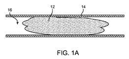
図1A乃至1Fは、塞栓除去ケージ10を使用して血管14から塞栓12を除去する様々な方法を示している。図1Aにおいて、塞栓12は、血管14の管腔16を塞いで、血管14を通る血液の流れを妨げている。塞栓12は、純粋に塞栓性のもの、すなわち血管14内または分岐点(図示省略)で引っ掛かるまで、順次小さくなる血管内に運ばれる塞栓(例えば、血栓の断片など)であってもよい。塞栓12は、純粋に血栓性のもの、すなわち血管14を塞ぐまで血管壁に形成される血栓であってもよい。代替的には、塞栓12は、塞栓的に引き起こされる血栓性の塊、すなわち塞栓から生じるせん断外乱により不完全に閉塞している塞栓に隣接して形成される血栓であってもよい。
FIGS. 1A-1F illustrate various methods of removing an
図1Bにおいて、カテーテル18が、血管14の壁に沿って塞栓12を越えて進められている。その後、プッシャワイヤ20に固定的に取り付けられた塞栓除去ケージ10は、塞栓12に隣接する管腔16内にカテーテルを介して進められる。代替的には、カテーテル18は、内部に塞栓除去ケージ10およびプッシャワイヤ16を収容した状態で、塞栓12を越えて進められるものであってもよい。
In FIG. 1B, the
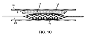
図1Cにおいて、カテーテル18は、塞栓12に対する塞栓除去ケージ10の相対位置を保持しながら、近位側に引き抜かれている。塞栓除去ケージ10は、自己拡張か、またはバルーンのような外部力による拡張によって、拡張している。拡張した塞栓除去ケージ10は、半径方向力を塞栓12に与えて、塞栓を血管14の壁に押し付ける。塞栓除去ケージ10は、塞栓12に進入して、少なくとも一時的に塞栓に固定される。血管14の壁から塞栓12を除去するために、3つの非相互排他的な機構を使用することができる。
In FIG. 1C, the
図1Dにおいて、塞栓除去ケージ10は、塞栓12の長さに比べて短い距離、遠位側に進められて近位側に引っ張られるのを繰り返し、かつ/または縦軸を中心に回転され、それにより、“チーズおろし器のような”作用を使用して、塞栓12の小断片22が削り取られる。“チーズおろし器のような”作用により分離された小断片22は、その後、吸引またはろ過により取り除かれる。また、小断片22は、酵素が利用できる表面を増加させ、酵素は、塞栓12の小断片22を少なくとも部分的に溶解することができる。この方法を使用して塞栓12の第1層が削り取られ後に、塞栓除去ケージ10を更に拡張させることができ、塞栓12が血管14から除去されるまで削取プロセスが繰り返される。
In FIG. 1D, the
図1Eにおいて、塞栓除去ケージ10は、プッシャワイヤ20を引っ張ることにより近位側に引き寄せられる。塞栓除去ケージ10は、近位側に移動するに間に、血管14の壁から塞栓12を引きはがす。その後、塞栓12は、塞栓除去ケージ10で取り除かれる。
In FIG. 1E, the
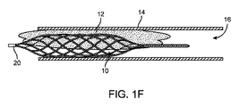
図1Fにおいて、塞栓除去ケージ10が塞栓12の隣接位置で拡張するとき、塞栓12内に入り込む。この塞栓除去ケージ10と塞栓12の係合は、塞栓除去ケージ10を塞栓12に一時的に固定する。塞栓除去ケージ10の縦軸に沿って力が加えられるとき、その係合が、塞栓除去ケージ10と塞栓12間の摩擦力を増加させる。プッシャワイヤ20をたぐり寄せることにより塞栓除去ケージ10が近位側に引き寄せられる間に、塞栓除去ケージ10は、血管14の壁から塞栓12を引きはがす。塞栓12は、その後、塞栓除去ケージ10で取り除かれる。
In FIG. 1F, the
上で示唆したように、図1Dおよび1Fに記載のステップは、血管14から塞栓12を除去するために、別々に、または互いに連動して使用することができる。この除去方法の限定因子は、塞栓12と係合する塞栓除去ケージ10の能力である。塞栓12と係合する塞栓除去ケージ12の能力は、当該塞栓除去ケージが配置される血管14の壁に損傷を与えることなく塞栓除去ケージ12が塞栓12に加えることができる半径方向力とともに増加する。この因子は、塞栓除去ケージ10の構造によって影響を受ける。
As suggested above, the steps described in FIGS. 1D and 1F can be used separately or in conjunction with each other to remove
図2Aおよび2Bは、ケージ10およびプッシャワイヤ20を含む、拡張状態にある本発明のデバイスの一実施形態を示している。図2Aに示すような幾つかの実施形態において、ケージ10は、拡張状態において、近位端26と遠位端28の両方で閉じられている。図2Bに示すようなその他の実施形態において、ケージ10は、一端のみが閉じられている。一実施形態(図示省略)において、ケージ10は、近位端26と遠位端28の両方で開放されている。図2Aに示すように、近位端26は、プッシャワイヤ20の遠位端に連結されている。ある実施形態(図示省略)において、近位端26および遠位端28がプッシャワイヤ20に連結されている。ケージ10をプッシャワイヤ20に取り付けるその他の構成も可能である。ある実施形態において、デバイスは、プッシャワイヤ20からケージ10を取り外す機能を有していない。このため、そのような実施形態においては、プッシャワイヤ20が血管から引き出されるときに、ケージ10が血管から取り除かれる。
2A and 2B illustrate one embodiment of the device of the present invention in an expanded state, including
図2Aに示すような幾つかの実施形態において、ケージ10は、当該ケージ10の壁32を形成するセル30の複数の外周バンドを有する。各セル30は、近位部、中心部および遠位部を有するセル壁34によって形成される。各セル壁34は、複数のストラット36により形成される。少なくとも図示の実施形態において、セル壁34は、近位のストラットペア38および遠位のストラットペア40を有する。セル壁34は、ケージの壁32に開口部42を規定する。
In some embodiments, as shown in FIG. 2A, the
シアリングのために構成された幾つかの実施形態において、少なくとも1のシアリングセルが、近位の弱い部分と遠位の強い部分とを有するセル壁によって定義される開口部42を有し、セル壁は、セル壁の遠位部分よりも大きく、半径方向に加えられる力に応答して、セル壁の中心部分の近傍で半径方向内向きに変形する。半径方向に加えられる力は、ある場合には、ケージが塞栓に接触するときに生じる。半径方向に加えられる力は、膨張力のように、均等に加えられる力であってもよい。ケージに加えられるその他の半径方向力は、セル壁の中心部分を、セル壁の遠位部分よりも大きく半径方向内向きに変形させる。ある実施形態において、中心部分の半径方向内向きの変形は、遠位部分の変形よりも、少なくとも約25%大きい。ある実施形態において、中心部分の半径方向内向きの変形は、遠位部分の変形よりも、少なくとも約30%大きい。
In some embodiments configured for shearing, at least one shearing cell has an
このようにケージ10が変形するため、ケージ10の他の部分が血管14の壁のより大きな部分に接触しながらも、シアリングセルの開口部42が塞栓12と係合するより好ましい状況が生じる。この接触部分の増加は(開口部42の少なくとも一部における強い遠位端とともに)、近位に引き寄せるときに、塞栓12の改善されたシアリングをもたらして、フィブリンネットワークを分断するとともに、塞栓12をケージ10内に捕捉する。
This deformation of the
セルの少なくとも一つにおいて、セルの中心部分は、半径方向に加えられる力に応答して、遠位部分よりも大きく、半径方向内向きに変形する。この少なくとも1のシアリングセルのセル壁34における変形により、ある実施形態では、ケージ10が、近位端と遠位端間の長さの少なくとも一部に沿って、不均一な直径を有する。少なくとも1の実施形態において、シアリングセルの中心部分の軸方向の長さLは、Dを治療される血管14の直径として、少なくとも約0.5Dである。ある実施形態において、Lは少なくとも約0.75Dである。ある実施形態において、Lは約1.0Dである。ある実施形態において、Lは約0.5Dと約3.0Dの間である。
In at least one of the cells, the central portion of the cell deforms radially inwardly larger than the distal portion in response to a radially applied force. Due to this deformation in the
図3は、セル30の複数の外周バンド44を有するケージ10の平面図である。各セルは、近位部分34a、中心部分34bおよび遠位部分34cを有するセル壁34により形成された四角形である。各セル壁34は、複数のストラット36により形成されている。少なくとも図示の実施形態において、セル壁34は、近位のストラットペア38および遠位のストラットペア40を有する。近位のストラットペア38は近位の頂角46を有し、近位のストラットペアは近位の頂角48を有する。
FIG. 3 is a plan view of the
それらセル30は、ケージの近位端26の近位端領域50に、第1中間領域52、第2中間領域54、第3中間領域56およびケージの遠位端の遠位端領域58に配置される。近位端領域50は第1中間領域52に連結され、この第1中間領域は第2中間領域54に連結され、この第2中間領域は第3中間領域56に連結され、この第3中間領域は遠位端領域58に連結される。各領域50,52,54,56,58は、セル30の少なくとも1の外周バンド44を有する。
The
図3に示す実施形態において、それら領域50,52,54,56,58の各々は、隣接する領域とは異なる構造のセル30を有し、それは、ケージ10の長さに沿って、セル30の不均一なパターン(よって、複数の不均一な開口部42)を作り出す。ある実施形態において、このセル30の不均一なパターン(よって、開口部42の不均一なパターンを規定する)は、ケージ10全体にわたって異なる半径方向の強さを有するセル30を、ケージ10が備えることを可能とし、それにより、少なくとも1の開口部が塞栓12のサイズまたは形状に応じて血管内の塞栓12(図1A乃至1Eを参照)と係合することを可能とする。ある実施形態において、セル30は、(例えば、ストラット36に異なる幅および/または厚みを持たせることにより)断面が不均一であるか、または(例えば、ストラット36に異なる長さを持たせることにより)サイズまたは形状が不均一である。
In the embodiment shown in FIG. 3, each of these
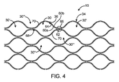
図4は、別の実施形態に係るケージ10の詳細平面図を示している。各セル30は、卵形、より具体的には、“レモンドロップ”形状を有する。当然のことながら、四角形および六角形のようなその他のセル形状も可能である。
FIG. 4 shows a detailed plan view of a
図4の実施形態において、セル壁34を形成するストラット36は、狭い間隔のほぼ平行な細長部材60のペア、各セル30に対して内側の細長部材60aおよび外側の細長部材60bにより形成されている。2つの軸方向に隣接するセル30,30’の内側の細長部材60aは互いに結合して、セル30間のノード66にノード相互接続部62を形成する。ノード相互接続部62は、セル30を軸方向に接続して、セル壁34を形成する。また、セル30は、2つの円周方向に隣接するセル30’’(1つのみ図示)も有する。
In the embodiment of FIG. 4, the
各セル30の内側の細長部材60aは、同じセル30の外側の細長部材60bに連結されて、セル30に関して大凡“4時”および“10時”の位置に2つのノード間相互接続部70を形成する。セル30の内側の細長部材60aおよび外側の細長部材60bは、斜めに(軸方向および円周方向の両方に)隣接するセル30’’’の外側および内側の細長部材であるため、ノード間相互接続部70は、セル30を斜めに連結して、セル壁34を形成する。
The
ペアを成す細長部材60a,60bは、スロット64を規定し、このスロットが、セル30間のノード66にまたがる。複数のノード66に及ぶスロット64を有するストラット36は、よりフレキシブルなケージ10をもたらす。外側の細長部材60bは、ノード66の隣接位置におけるその連続する長さの増加により、ノード66において内側の細長部材60aよりもフレキシブルとなる。2つの細長部材60a,60b間の異なるフレキシビリティは、塞栓12から半径方向の圧力を受けたときに(図1A乃至1Fを参照)、2つの細長部材60a,60bを使用中に互いに分離するという結果をもたらす。この細長部材60a,60bの分離は、細長部材60a,60bのサイズの縮小により、塞栓12内への進入を改善することができ、細長部材60a,60bおよび塞栓12間の接触面積の増加により、塞栓12に対する固定を改善することができる。細長部材60a,60bは、使用中に分離して、その際に、ノード66の“Y”形状部68において、軸方向の力に応答する硬いストラットとして機能し、シアリングを増加させることができる。
The pair of
図4において、4つの内側の細長部材60a、すなわち2つの軸方向に隣接するセル30,30’の各々からの2つは、セル30,30’間のノード66で結合し、ノード相互接続部62を形成する。また、2つの外側の細長部材60bは、ノード66を通って一方のセル30から軸方向に隣接するセル30’に至る。この実施形態においては、1つの(4細長部材)ノード相互接続部62を形成する、4つの結合する細長部材60と、ノード66において結合を形成しない、各ノード66で迂回する2つの細長部材60とが存在する。
In FIG. 4, four inner
ペアを成す細長部材のストラット構造は、フレキシビリティを最大化しながらも、任意の力、例えば半径方向力を、より広い領域に亘って分配する。また、ペアを成す細長部材のストラット構造は、セル30間で非共有の細長部材60をもたらす。図4は一つの特定の細長部材の分割および結合パターンを示しているが、その他のパターンも可能である。
The pair of elongated member strut structures distribute any force, eg, radial force, over a larger area while maximizing flexibility. The pair of elongated member strut structures also provide a non-shared elongated member 60 between
例えば、図5は、別の実施形態に係るケージ10の詳細平面図を示している。この実施形態において、セル30間のすべての結合は、ノード66,66’で生じる。斜めに隣接するセル30,30’’’は、“12時”および“6時”に位置する(セル30に対して)円周方向のノード66’で連結される。軸方向に隣接するセル30,30’は、軸方向のノード66で連結される。ノードが軸方向のノード66であるのか、または円周方向のノード66’であるのかは、基準とするセルに依存する。
For example, FIG. 5 shows a detailed plan view of a
このケージ10のセル壁34を形成するストラット36も、それぞれほぼ平行な細長部材60のペアからなるが、細長部材60は、連続的ではない。外側の細長部材60bの各々は、軸方向のノード66間に切断部72を含み、内側の細長部材60aの各々は、軸方向のノード66の各々に切断部72を含む。
The
各セル30の4つの細長部材60は、各軸方向ノード66に配置されている。一方の内側の細長部材60aは、軸方向ノード66で平行な外側の細長部材60bと結合することにより、終わりとなる。他方の内側の細長部材60a’は、軸方向ノード66を通って一方のセル30から軸方向に隣接するセル30’に至る。この内側の細長部材60a’は、軸方向ノード66を通過すると、軸方向に隣接するセル30’において反対側で内側の細長部材60a’になる。この実施形態では、2つの(3細長部材)ノード相互接続部62を形成する、6つの結合する細長部材60と、軸方向ノード66において結合を形成しない、各軸方向ノード66で迂回する1つの細長部材60a’とが存在する。この実施形態では、各セル30からの3つの細長部材(60a’,60b,60b’)が軸方向ノード66で相互に結合し、1つの細長部材(60a’)が軸方向ノード66を迂回する。
Four elongated members 60 of each
各セル30からの4つの細長部材60は、各円周方向ノード66’に配置されている。一方の外側の細長部材60b’は、円周方向ノード66’で平行な内側の細長部材60aと結合することにより、終わりとなる。他方の外側の細長部材60bは、円周方向ノード66’を通って一方のセル30から斜めに隣接するセル30’’’に至る。外側の細長部材60bは、円周方向ノード66’を通過すると、斜めに隣接するセル30’’’において反対側で外側の細長部材60aになる。この実施形態では、2つの(3細長部材)ノード相互接続部62を形成する、6つの結合する細長部材60と、円周方向ノード66’において結合を形成しない、各円周方向ノード66’で迂回する1つの細長部材60bとが存在する。この実施形態では、3つの細長部材(60a,60a’,60b’)が円周方向ノード66’で相互に結合し、1つの細長部材(60b)が円周方向ノード66’を迂回する。
Four elongate members 60 from each
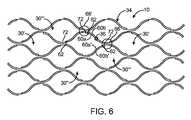
図6の実施形態は、図5におけるそれと類似している。図5の実施形態と同様に、図6の実施形態において、セル30間のすべての結合は、ノード66,66’で生じる。斜めに隣接するセル30,30’’’は、“12時”および“6時”に位置する(セル30に対して)円周方向ノード66’で連結される。軸方向に隣接するセル30,30’は、軸方向ノード66で連結される。
The embodiment of FIG. 6 is similar to that in FIG. Similar to the embodiment of FIG. 5, in the embodiment of FIG. 6, all coupling between
このケージ10のセル壁34を形成するストラット36も、それぞれほぼ平行な細長部材60のペアからなるが、細長部材60は、連続的ではない。内側の細長部材60aの各々は、軸方向ノード66間に切断部72を含み、外側の細長部材60bの各々は、各軸方向ノード66に切断部72を含む。軸方向ノード66間の内側の細長部材60aの切断部72において、内側の細長部材60aは、円周方向ノード66’のノード相互接続部62で、平行な外側の細長部材60bと結合する。その地点で、平行な外側の細長部材60bは、切断部72によってその平行な外側の細長部材60bから分離された内側の細長部材60aとなる。
The
各セル30からの4つの細長部材60は、各軸方向ノード66に配置されている。一方の外側の細長部材60bは、軸方向ノード66で平行な内側の細長部材60aと結合することにより、終わりとなる。他方の内側の細長部材60a’は、軸方向ノード66を通って一方のセル30から軸方向に隣接するセル30’に至る。内側の細長部材60a’は、軸方向ノード66を通過すると、軸方向に隣接するセル30’において反対側で内側の細長部材60aになる。この実施形態では、2つの(3細長部材)ノード相互接続部62を形成する、6つの結合する細長部材60と、軸方向ノード66において結合を形成しない、1つの各軸方向ノード66で迂回する1つの細長部材60a’とが存在する。この実施形態では、3つの細長部材(60a,60b,60b’)が軸方向ノード66で相互に結合し、1つの細長部材(60a’)が軸方向ノード66を迂回する。
Four elongated members 60 from each
各セル30からの4つの細長部材60は、各円周方向ノード66’に配置されている。一方の内側の細長部材60aは、円周方向ノード66’で平行な外側の細長部材60bと結合することにより、終わりとなる。他方の外側の細長部材60bは、円周方向ノード66’を通って一方のセル30から斜めに隣接するセル30’’’に至る。外側の細長部材60bは、円周方向ノード66’を通過すると、斜めに隣接するセル30’’’の反対側で内側の細長部材60aになる。この実施形態では、2つの(3細長部材)ノード相互接続部62を形成する、6つの結合する細長部材60と、円周方向ノード66’において結合を形成しない、各円周方向ノード66’で迂回する1つの細長部材60bとが存在する。この実施形態では、各セル30からの3つの細長部材(60a,60a’,60b’)が円周方向ノード66’で相互に結合し、1つの細長部材(60b)が円周方向ノード66’を迂回する。
Four elongate members 60 from each
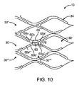
図10は、更に別の実施形態に係るケージ10の詳細平面図である。この実施形態の軸方向ノード66は、2つの軸方向に隣接するセル30,30’の4つの細長部材60a,60a’,60a’’,60a’’’がノード66で互いに結合して、ノード相互接続部62を形成している点で、図4の実施形態と同様である。ノード相互接続部62はセル30を軸方向に連結してセル壁34を形成する。セル30は、2つの円周方向に隣接するセル30’’を有する。この実施形態では、各ノード62において、結合を形成することなくノードにまたがる細長部材60b’であって、単一のセル30’’’’内に留まって非連結リーフ78を形成する細長部材60が存在する。
FIG. 10 is a detailed plan view of a
図4−6および10の実施形態におけるセル30は“閉じており”、塞栓ケージ10の抜き出しおよび再挿入と干渉する長手方向に自由端が存在しない。そのような自由端は、カテーテル18および血管14に引っ掛かって損傷を与える可能性がある。
The
実施形態の何れにおいても、内側および外側の細長部材(60a,60b)は、異なるフレキシビリティを有し、2つの細長部材60a,60b間のフレキシビリティの差を最大化することができる。例えば、内側および外側の細長部材(60a,60b)は、異なる断面形状、すなわち円形、卵形、長方形、三角形等を有することができる。
In any of the embodiments, the inner and outer elongated members (60a, 60b) have different flexibility and can maximize the difference in flexibility between the two
さらに、ストラット36は、ストラット36、セル30およびケージ10の一部のフレキシビリティをより正確に制御するために、ペアとなる細長部材の構造を有する部分と、硬い構造を有するその他の部分とを備える。
In addition, the
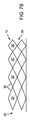
少なくとも1の実施形態において、ケージ10は、完全な拡張時に、その長さの少なくとも一部に沿ってほぼ一定の直径を有する。その他の実施形態では、近位端26から遠位端28に向けて先細となる直径(またはその少なくとも一部)を有するケージを備えることが望ましい場合があり、あるいは逆に、ケージが完全に拡張したときに、図7Aに示すように、ケージ10は、遠位端28から近位端26に向けて先細となる直径(またはその少なくとも一部)を備えることもできる。先細の直径を有するケージを作成するために様々な方法を使用することができる。ケージの先細の直径は、(図7Bに示すように)近位端26から遠位端28へとケージの長さに沿って各セル30のストラット36の長さを徐々に短くすることにより、または(図7Cに示すように)近位端26から遠位端28へとケージの長さに沿って各セル30のストラット36の幅または厚みを徐々に増やすことにより、または(図7Dに示すように)近位端26から遠位端28へとケージの長さに沿ってセル密度(つまり、単位領域あたりのセル30の数)を徐々に増やすことにより、またはその他の適当な方法により、達成することができる。
In at least one embodiment, the
ある実施形態では、完全に拡張したときに近位端から遠位端にかけて可変直径を有するケージを備え、図8Aに示すように、ケージ10の長さの少なくとも一部に沿って繰り返し直径が増加および減少することが望ましい場合がある。そのようなケージ10は、(図8Bに示すように)遠位ストラットペア40のストラット36の長さよりも近位のストラットペア38のストラット36の長さを長くすることにより、または(図8Cに示すように)遠位ストラットペア40のストラット36を近位ストラットペア38のストラット36よりも長くてより厚くまたは広くすることにより、または(図8Dに示すように)小さい直径が望ましい位置におけるセル30の数(またはセル密度)を増やすことにより、またはその他の適当な方法により、達成することができる。ケージのその他の構成(例えば、ケージのある部分における先細の直径およびケージに沿う他の部分における可変直径およびその他の組合せ)も可能である。
In certain embodiments, a cage having a variable diameter from the proximal end to the distal end when fully expanded, with repeated diameter increases along at least a portion of the length of the
図9の塞栓除去ケージ10は、ペアを成す細長部材60a,60bと、ペアを成さない細長部材60cとから形成されている。細長部材60により規定される各セル30は、2つの領域74,76を有する。概して図9の左側または塞栓除去ケージ10の近位側にある一方の領域74は、ペアを成さない細長部材60cにより規定されている。概して図9の右側または塞栓除去ケージ10の遠位側にある他方の領域76は、ペアを成す細長部材60a,60bにより規定されている。この実施形態では、ペアを成さない細長部材60cがペアを成す細長部材60a,60bと異なるサイズであるが、細長部材60a,60b,60cは同じサイズとすることもできる。
The
ある実施形態では、塞栓除去ケージ10を、チューブからレーザで切り取ることができる。また、平坦シートから切り取って継ぎ目で溶接することもできる。
In some embodiments, the
ある実施形態では、ケージに、遠位に取り付けられた捕集具またはネットを設けることができる。そのような実施形態では、ネットが血管腔の可能な最大限まで開くようにするために、ネットの近位部を高半径方向圧力領域とすべきである。 In certain embodiments, the cage can be provided with a distally attached collector or net. In such an embodiment, the proximal portion of the net should be a high radial pressure region so that the net opens to the fullest extent possible in the vessel lumen.
ある実施形態では、ケージ10の壁は、近位端と遠位端の間の単一層において壁に沿う任意の場所に提供される構造的材料から形成される。少なくとも1の実施形態では、ニチノール、PET、PTFEおよびその他の生体適合性材料のような、金属、ポリマー、複合材料及びその他の材料からなる硬性チューブからケージ10が切り取られる。また、成形構造またはその他のワイヤ無しの構造からケージを作ることもできる。幾つかの実施形態では、ニチノール、PET、PTFEおよびその他の生体適合性材料のような材料のワイヤをマンドレルの周囲で編むことにより、ケージの壁を形成することができる。
In certain embodiments, the wall of the
ある実施形態では、ケージは、その任意の面上で、完全にまたは部分的に物質により被覆され、その物質には、薬、遺伝物質、細胞、治療薬、治療成分を有するポリマーマトリクス、塞栓を溶解するのに使用される血栓溶解物質、または体腔に送達するのが望ましいその他の物質が含まれるが、それらに限定されるものではない。治療薬は、薬またはその他の医薬品、例えば、非遺伝的物質、遺伝物質、細胞物質などであってもよい。適当な非遺伝的治療薬の例としては、例えば、ヘパリンなどの抗血栓症薬、ヘパリン誘導体、血管細胞成長促進物質、成長因子阻害剤、パクリタキセルを含むが、それらに限定されるものではない。遺伝物質が遺伝治療薬を含む場合には、そのような遺伝物質は、DNA、RNAおよびそれらの誘導体および/または化学成分、ヘッジホッグタンパク質等を含むことができるが、それらに限定されるものではない。治療薬が細胞物質を含む場合には、細胞物質は、ヒト由来の細胞および/または非ヒト由来の細胞、それらの成分および/または誘導体を含むが、それらに限定されるものではない。治療薬が高分子剤を含む場合には、高分子剤は、ポリスチレン−ポリイソブチレン−ポリスチレントリブロック共重合体(SIBS)、ポリエチレンオキシド、シリコーンゴムおよび/またはその他の適当な物質であってもよい。 In certain embodiments, the cage is completely or partially coated with a substance on any surface thereof, including a drug, genetic material, cell, therapeutic agent, polymer matrix with therapeutic component, embolus. These include, but are not limited to, thrombolytic substances used to dissolve, or other substances that are desirably delivered to body cavities. The therapeutic agent may be a drug or other pharmaceutical agent, such as non-genetic material, genetic material, cellular material, and the like. Examples of suitable non-genetic therapeutic agents include, but are not limited to, antithrombotic agents such as heparin, heparin derivatives, vascular cell growth promoters, growth factor inhibitors, and paclitaxel. Where the genetic material includes a genetic therapeutic agent, such genetic material can include, but is not limited to, DNA, RNA and their derivatives and / or chemical components, hedgehog proteins, and the like. Absent. Where the therapeutic agent includes cellular material, the cellular material includes, but is not limited to, human-derived cells and / or non-human derived cells, components and / or derivatives thereof. Where the therapeutic agent includes a polymeric agent, the polymeric agent may be a polystyrene-polyisobutylene-polystyrene triblock copolymer (SIBS), polyethylene oxide, silicone rubber, and / or other suitable material. .
さらに、従属請求項に提示される特定の特徴は、互いに組み合わせることができ、本発明は、従属請求項の特徴のその他の可能性のある組合せを有するその他の実施形態も明確に対象にしているものとして認識されるべきである。例えば、請求項の公開のために、後に続く任意の従属請求項は、多項従属形式が管轄権内で受け入れられる形式である場合に、そのような従属請求項に引用されるすべての先行詞を有するすべての先行する請求項から多項従属形式で代替的に記載されているとして捉えるべきである(例えば、請求項1に直接従属する各請求項は、すべての先行する請求項に従属するものとして代替的に捉えるべきである)。多項従属請求項の形式が制限を受ける管轄権内においては、続く従属請求項は各々、従属請求項に記載の特定の請求項以外の先行する先行詞保有の請求項から従属関係を生じさせるような、単項従属形式に代替的に記載されているとして捉えるべきである(例えば、請求項3が請求項2に代替的に従属しているとして捉え、請求項4が請求項2または請求項3に代替的に従属しているとして捉え、請求項6が請求項5に代替的に従属しているとして捉える等が可能である)。 Furthermore, the specific features presented in the dependent claims can be combined with each other, and the present invention explicitly covers other embodiments having other possible combinations of the features of the dependent claims. It should be recognized as a thing. For example, for the publication of a claim, any subsequent dependent claim shall include all antecedents cited in such dependent claim if the multiple dependent form is in a form acceptable within the jurisdiction. Should be construed as being alternatively stated in multiple dependent form from all preceding claims (eg, each claim directly dependent on claim 1 is dependent on all preceding claims) Should be taken as an alternative). Within the jurisdiction in which the form of a multiple dependent claim is restricted, each subsequent dependent claim will cause a subordinate relationship from the preceding antecedent claim other than the specific claim stated in the dependent claim. It should be construed as being alternatively described in a single dependent form (for example, claim 3 is regarded as being alternatively dependent on claim 2, and claim 4 is claim 2 or claim 3). And claim 6 can be regarded as being subordinate to claim 5).
Claims (12)
複数の対の、密接したほぼ平行な細長部材であって、前記長手軸の方向に配置され、複数の開放したセルを共同で規定する細長部材を具え、
第1の対の細長部材の内側細長部材が、第2の対の細長部材の内側細長部材に、軸方向に隣接する第1の対のセルと円周方向に隣接する第1の対のセルとの間に位置する第1のノードで連結されており、
第1の対の細長部材の外側細長部材と、第2の対の細長部材の外側細長部材とが、他のノードに結合することなく前記第1のノードにまたがっており、前記第2の対の細長部材の外側細長部材が、第3の対の細長部材の外側細長部材とともに第2のノードを形成し、当該第2のノードは、軸方向に隣接する第2の対のセルと円周方向に隣接する第2の対のセルとの間に位置し、
前記第1の対の細長部材の内側細長部材が、前記第2の対の細長部材の内側細長部材に第3のノードで連結され、当該第3のノードは、前記第2のノードが、前記第1および第3のノードの間になるように前記第1のノードから離間しており、
前記第1の対の細長部材の内側細長部材と外側細長部材は、前記第1のノードと前記第3のノードの間に位置する第1のノード間相互接続部で互いに連結されており、
前記第2の対の細長部材の内側細長部材と外側細長部材は、前記第1のノードと前記第2のノードの間に位置する第2のノード間相互接続部で互いに連結されていることを特徴とする塞栓除去ケージ。 An embolus removal cage having a longitudinal axis and an outer periphery,
A plurality of pairs of closely parallel elongated members, disposed in the direction of the longitudinal axis and comprising jointly defining a plurality of open cells;
An inner elongate member of the first pair of elongate members is a first pair of cells circumferentially adjacent to an inner elongate member of the second pair of elongate members axially adjacent to the first pair of cells. Are connected by a first node located between
An outer elongate member of the first pair of elongate members and an outer elongate member of the second pair of elongate members span the first node without being coupled to other nodes, and the second pair The outer elongate member of the second elongate member forms a second node with the outer elongate member of the third pair of elongate members, the second node being circumferential with the second pair of cells adjacent in the axial direction. Located between a second pair of cells adjacent in the direction;
An inner elongate member of the first pair of elongate members is connected to an inner elongate member of the second pair of elongate members at a third node, the third node is connected to the second node, and Spaced from the first node to be between the first and third nodes;
The inner elongated member and the outer elongated member of the first pair of elongated members are connected to each other at a first internode interconnect located between the first node and the third node;
The inner elongate member and the outer elongate member of the second pair of elongate members are connected to each other at a second inter-node interconnect located between the first node and the second node. Features an embolus removal cage.
Applications Claiming Priority (3)
| Application Number | Priority Date | Filing Date | Title |
|---|---|---|---|
| US201161576958P | 2011-12-16 | 2011-12-16 | |
| US61/576,958 | 2011-12-16 | ||
| PCT/US2012/068281 WO2013090122A1 (en) | 2011-12-16 | 2012-12-06 | Embolectomy cage |
Publications (3)
| Publication Number | Publication Date |
|---|---|
| JP2015503946A JP2015503946A (en) | 2015-02-05 |
| JP2015503946A5 JP2015503946A5 (en) | 2015-10-08 |
| JP6069348B2 true JP6069348B2 (en) | 2017-02-01 |
Family
ID=47505310
Family Applications (1)
| Application Number | Title | Priority Date | Filing Date |
|---|---|---|---|
| JP2014547301A Active JP6069348B2 (en) | 2011-12-16 | 2012-12-06 | Embolization removal cage |
Country Status (6)
| Country | Link |
|---|---|
| US (1) | US9439750B2 (en) |
| EP (1) | EP2790598B1 (en) |
| JP (1) | JP6069348B2 (en) |
| CN (1) | CN103997976B (en) |
| ES (1) | ES2633347T3 (en) |
| WO (1) | WO2013090122A1 (en) |
Families Citing this family (63)
| Publication number | Priority date | Publication date | Assignee | Title |
|---|---|---|---|---|
| US9402707B2 (en) | 2008-07-22 | 2016-08-02 | Neuravi Limited | Clot capture systems and associated methods |
| US9463036B2 (en) | 2010-10-22 | 2016-10-11 | Neuravi Limited | Clot engagement and removal system |
| US11259824B2 (en) | 2011-03-09 | 2022-03-01 | Neuravi Limited | Clot retrieval device for removing occlusive clot from a blood vessel |
| WO2012120490A2 (en) | 2011-03-09 | 2012-09-13 | Neuravi Limited | A clot retrieval device for removing occlusive clot from a blood vessel |
| US11083475B2 (en) | 2012-02-22 | 2021-08-10 | Carter J. Kovarik | Medical device to remove an obstruction from a body lumen, vessel or organ |
| US9901245B2 (en) | 2012-02-22 | 2018-02-27 | Carter J. Kovarik | Selectively bendable remote gripping tool |
| US10226266B2 (en) | 2012-02-22 | 2019-03-12 | Carter J. Kovarik | Selectively bendable remote gripping tool |
| US9592066B2 (en) | 2012-02-22 | 2017-03-14 | Carter J. Kovarik | Selectively bendable remote gripping tool |
| US9832980B2 (en) | 2012-02-22 | 2017-12-05 | Carter J. Kovarik | Selectively bendable remote gripping tool |
| USD780547S1 (en) | 2013-08-08 | 2017-03-07 | Carter J. Kovarik | Pick up device with flexible shaft portion |
| US9642635B2 (en) | 2013-03-13 | 2017-05-09 | Neuravi Limited | Clot removal device |
| ES2713633T3 (en) | 2013-03-14 | 2019-05-23 | Neuravi Ltd | Devices and methods for elimination of severe blockages of blood vessels |
| US9433429B2 (en) | 2013-03-14 | 2016-09-06 | Neuravi Limited | Clot retrieval devices |
| JP2016513505A (en) | 2013-03-14 | 2016-05-16 | ニューラヴィ・リミテッド | Clot collection device for removing obstructed clots from blood vessels |
| US10076399B2 (en) * | 2013-09-13 | 2018-09-18 | Covidien Lp | Endovascular device engagement |
| US10285720B2 (en) | 2014-03-11 | 2019-05-14 | Neuravi Limited | Clot retrieval system for removing occlusive clot from a blood vessel |
| US10441301B2 (en) | 2014-06-13 | 2019-10-15 | Neuravi Limited | Devices and methods for removal of acute blockages from blood vessels |
| US10792056B2 (en) | 2014-06-13 | 2020-10-06 | Neuravi Limited | Devices and methods for removal of acute blockages from blood vessels |
| US10265086B2 (en) | 2014-06-30 | 2019-04-23 | Neuravi Limited | System for removing a clot from a blood vessel |
| EP2987463A1 (en) * | 2014-08-21 | 2016-02-24 | Noureddine Frid | 3d filter for prevention of stroke |
| DE102014222600A1 (en) * | 2014-11-05 | 2016-05-12 | Epflex Feinwerktechnik Gmbh | Medical safety wire instrument |
| EP3682821B1 (en) | 2014-11-26 | 2022-05-11 | Neuravi Limited | A clot retrieval device for removing an occlusive clot from a blood vessel |
| US11253278B2 (en) | 2014-11-26 | 2022-02-22 | Neuravi Limited | Clot retrieval system for removing occlusive clot from a blood vessel |
| US10617435B2 (en) * | 2014-11-26 | 2020-04-14 | Neuravi Limited | Clot retrieval device for removing clot from a blood vessel |
| IL253851B2 (en) * | 2015-02-06 | 2023-10-01 | Rapid Medical Ltd | Systems and methods for intravascular obstruction removal |
| JP6072384B1 (en) * | 2015-03-13 | 2017-02-01 | オリンパス株式会社 | Treatment tool |
| CN107530098B (en) * | 2015-04-16 | 2020-01-24 | 斯瑞克公司 | Embolectomy device and method |
| EP3352686A1 (en) * | 2015-09-24 | 2018-08-01 | NeuVT Limited | Neurovascular occlusion device |
| CN112043457A (en) * | 2015-11-04 | 2020-12-08 | 急速医疗有限公司 | Intraluminal device |
| RU2018122453A (en) * | 2015-11-25 | 2019-12-26 | Ньюрави Лимитед | BLOOD REMOVAL DEVICE FOR REMOVING THE OCCLUSION BLOCK FROM BLOODY VESSEL |
| EP3782562A1 (en) | 2016-08-17 | 2021-02-24 | Neuravi Limited | A clot retrieval system for removing occlusive clot from a blood vessel |
| MX2019002565A (en) | 2016-09-06 | 2019-09-18 | Neuravi Ltd | A clot retrieval device for removing occlusive clot from a blood vessel. |
| CN107049421B (en) * | 2017-05-09 | 2023-11-17 | 心凯诺医疗科技(上海)有限公司 | Full-development thrombus taking support and thrombus taking device |
| CN106955140B (en) * | 2017-05-09 | 2023-07-25 | 心凯诺医疗科技(上海)有限公司 | Thrombus taking support and thrombus taking device |
| CN107049420B (en) * | 2017-05-09 | 2023-10-31 | 心凯诺医疗科技(上海)有限公司 | Thrombus taking support and thrombus taking device |
| CN107137125B (en) * | 2017-06-20 | 2023-08-04 | 微创神通医疗科技(上海)有限公司 | Bolt taking support and bolt taking device |
| CN109938801A (en) * | 2017-12-21 | 2019-06-28 | 新昕医药科技(上海)有限公司 | A kind of thrombus takes bolt device |
| US10667833B2 (en) * | 2018-06-08 | 2020-06-02 | Neuravi Limited | Guidewire with an atraumatic clot-circumventing configured distal end for use in an endovascular medical system |
| US10842498B2 (en) | 2018-09-13 | 2020-11-24 | Neuravi Limited | Systems and methods of restoring perfusion to a vessel |
| US11406416B2 (en) | 2018-10-02 | 2022-08-09 | Neuravi Limited | Joint assembly for vasculature obstruction capture device |
| EP4000540B1 (en) | 2019-03-04 | 2024-02-14 | Neuravi Limited | Actuated clot retrieval catheter |
| US11529495B2 (en) | 2019-09-11 | 2022-12-20 | Neuravi Limited | Expandable mouth catheter |
| US11712231B2 (en) | 2019-10-29 | 2023-08-01 | Neuravi Limited | Proximal locking assembly design for dual stent mechanical thrombectomy device |
| US11779364B2 (en) | 2019-11-27 | 2023-10-10 | Neuravi Limited | Actuated expandable mouth thrombectomy catheter |
| US11839725B2 (en) | 2019-11-27 | 2023-12-12 | Neuravi Limited | Clot retrieval device with outer sheath and inner catheter |
| US11517340B2 (en) | 2019-12-03 | 2022-12-06 | Neuravi Limited | Stentriever devices for removing an occlusive clot from a vessel and methods thereof |
| CN112890913B (en) * | 2019-12-03 | 2022-05-20 | 先健科技(深圳)有限公司 | Thrombus taking device and thrombus taking device |
| US11944327B2 (en) | 2020-03-05 | 2024-04-02 | Neuravi Limited | Expandable mouth aspirating clot retrieval catheter |
| US11633198B2 (en) | 2020-03-05 | 2023-04-25 | Neuravi Limited | Catheter proximal joint |
| US11883043B2 (en) | 2020-03-31 | 2024-01-30 | DePuy Synthes Products, Inc. | Catheter funnel extension |
| US11759217B2 (en) | 2020-04-07 | 2023-09-19 | Neuravi Limited | Catheter tubular support |
| US11717308B2 (en) | 2020-04-17 | 2023-08-08 | Neuravi Limited | Clot retrieval device for removing heterogeneous clots from a blood vessel |
| US11730501B2 (en) | 2020-04-17 | 2023-08-22 | Neuravi Limited | Floating clot retrieval device for removing clots from a blood vessel |
| US11871946B2 (en) | 2020-04-17 | 2024-01-16 | Neuravi Limited | Clot retrieval device for removing clot from a blood vessel |
| US11737771B2 (en) | 2020-06-18 | 2023-08-29 | Neuravi Limited | Dual channel thrombectomy device |
| US11937836B2 (en) | 2020-06-22 | 2024-03-26 | Neuravi Limited | Clot retrieval system with expandable clot engaging framework |
| US11395669B2 (en) | 2020-06-23 | 2022-07-26 | Neuravi Limited | Clot retrieval device with flexible collapsible frame |
| US11439418B2 (en) | 2020-06-23 | 2022-09-13 | Neuravi Limited | Clot retrieval device for removing clot from a blood vessel |
| US11864781B2 (en) | 2020-09-23 | 2024-01-09 | Neuravi Limited | Rotating frame thrombectomy device |
| US11937837B2 (en) | 2020-12-29 | 2024-03-26 | Neuravi Limited | Fibrin rich / soft clot mechanical thrombectomy device |
| US11872354B2 (en) | 2021-02-24 | 2024-01-16 | Neuravi Limited | Flexible catheter shaft frame with seam |
| CN113598884B (en) * | 2021-08-06 | 2022-11-25 | 内蒙古工业大学 | Broken bolt assembly and blood vessel thrombus treatment device |
| US11937839B2 (en) | 2021-09-28 | 2024-03-26 | Neuravi Limited | Catheter with electrically actuated expandable mouth |
Family Cites Families (16)
| Publication number | Priority date | Publication date | Assignee | Title |
|---|---|---|---|---|
| US6485507B1 (en) * | 1999-07-28 | 2002-11-26 | Scimed Life Systems | Multi-property nitinol by heat treatment |
| US6575997B1 (en) | 1999-12-23 | 2003-06-10 | Endovascular Technologies, Inc. | Embolic basket |
| US6402771B1 (en) * | 1999-12-23 | 2002-06-11 | Guidant Endovascular Solutions | Snare |
| US6660021B1 (en) * | 1999-12-23 | 2003-12-09 | Advanced Cardiovascular Systems, Inc. | Intravascular device and system |
| US20020058904A1 (en) | 2000-11-08 | 2002-05-16 | Robert Boock | Thrombus removal device |
| US20040186551A1 (en) * | 2003-01-17 | 2004-09-23 | Xtent, Inc. | Multiple independent nested stent structures and methods for their preparation and deployment |
| US20040199201A1 (en) * | 2003-04-02 | 2004-10-07 | Scimed Life Systems, Inc. | Embolectomy devices |
| EP1981413B1 (en) | 2006-02-01 | 2014-11-12 | The Cleveland Clinic Foundation | An apparatus for increasing blood flow through an obstructed blood vessel |
| CN101516259B (en) | 2006-09-15 | 2011-07-20 | 心脏起搏器公司 | Anchor for an implantable sensor |
| BRPI0908500A8 (en) * | 2008-02-22 | 2018-10-23 | Micro Therapeutics Inc | imaging methods of restoration of thrombus-occluded blood vessel blood flow, partial or substantial dissolution and thrombus dislocation, self-expanding thrombus removal equipment and integrated removable thrombus mass |
| DE102008038195A1 (en) * | 2008-08-19 | 2010-02-25 | Phenox Gmbh | Device for opening occluded blood vessels |
| US20100318171A1 (en) * | 2009-06-15 | 2010-12-16 | Boston Scientific Scimed, Inc. | Multiple Stent Delivery System |
| US8795317B2 (en) * | 2009-07-08 | 2014-08-05 | Concentric Medical, Inc. | Embolic obstruction retrieval devices and methods |
| US20110009941A1 (en) * | 2009-07-08 | 2011-01-13 | Concentric Medical, Inc. | Vascular and bodily duct treatment devices and methods |
| DE102010045367B4 (en) * | 2010-05-18 | 2019-08-08 | Acandis Gmbh | Medical device for removing concrements |
| WO2012064726A1 (en) | 2010-11-12 | 2012-05-18 | Stryker Corporation | Axially variable radial pressure cages for clot capture |
-
2012
- 2012-12-06 CN CN201280062132.6A patent/CN103997976B/en active Active
- 2012-12-06 WO PCT/US2012/068281 patent/WO2013090122A1/en active Application Filing
- 2012-12-06 EP EP12810462.7A patent/EP2790598B1/en active Active
- 2012-12-06 US US13/707,375 patent/US9439750B2/en active Active
- 2012-12-06 ES ES12810462.7T patent/ES2633347T3/en active Active
- 2012-12-06 JP JP2014547301A patent/JP6069348B2/en active Active
Also Published As
| Publication number | Publication date |
|---|---|
| CN103997976A (en) | 2014-08-20 |
| ES2633347T3 (en) | 2017-09-20 |
| US20130158592A1 (en) | 2013-06-20 |
| EP2790598A1 (en) | 2014-10-22 |
| US9439750B2 (en) | 2016-09-13 |
| CN103997976B (en) | 2016-11-16 |
| EP2790598B1 (en) | 2017-04-26 |
| WO2013090122A1 (en) | 2013-06-20 |
| JP2015503946A (en) | 2015-02-05 |
Similar Documents
| Publication | Publication Date | Title |
|---|---|---|
| JP6069348B2 (en) | Embolization removal cage | |
| JP6873233B2 (en) | Blood clot collection device for the treatment of ischemic stroke | |
| JP7169971B2 (en) | Obstruction removal system | |
| EP3585282B1 (en) | Embolectomy device having multiple semi-tubular clot engaging structures | |
| US20220330962A1 (en) | Multi-pivot thrombectomy device | |
| US20210259720A1 (en) | Clot retrieval device for removing a clot from a blood vessel | |
| JP7369034B2 (en) | Controllable retrieval device with distal clot anchor | |
| JP6745848B2 (en) | Clot collection device for removing occluded clots from blood vessels | |
| US20120123466A1 (en) | Axially variable radial pressure cages for clot capture | |
| DE102010014778A1 (en) | Medical device for e.g. removing thrombus from curved blood vessel, has suction opening turnable towards calculus such that calculus is connected with suction element over low pressure laterally transferable from line and suction element | |
| EP3352688A1 (en) | Embolectomy devices | |
| EP3895636B1 (en) | A floating clot retrieval device for removing clots from a blood vessel | |
| KR20200133754A (en) | Thrombectomy device | |
| JP2022554265A (en) | Retrieval device with raised features for thrombectomy |
Legal Events
| Date | Code | Title | Description |
|---|---|---|---|
| A521 | Request for written amendment filed |
Free format text: JAPANESE INTERMEDIATE CODE: A523 Effective date: 20150818 |
|
| A621 | Written request for application examination |
Free format text: JAPANESE INTERMEDIATE CODE: A621 Effective date: 20150818 |
|
| A977 | Report on retrieval |
Free format text: JAPANESE INTERMEDIATE CODE: A971007 Effective date: 20160629 |
|
| A131 | Notification of reasons for refusal |
Free format text: JAPANESE INTERMEDIATE CODE: A131 Effective date: 20160719 |
|
| A521 | Request for written amendment filed |
Free format text: JAPANESE INTERMEDIATE CODE: A523 Effective date: 20160825 |
|
| TRDD | Decision of grant or rejection written | ||
| A01 | Written decision to grant a patent or to grant a registration (utility model) |
Free format text: JAPANESE INTERMEDIATE CODE: A01 Effective date: 20161220 |
|
| A61 | First payment of annual fees (during grant procedure) |
Free format text: JAPANESE INTERMEDIATE CODE: A61 Effective date: 20161226 |
|
| R150 | Certificate of patent or registration of utility model |
Ref document number: 6069348 Country of ref document: JP Free format text: JAPANESE INTERMEDIATE CODE: R150 |
|
| S111 | Request for change of ownership or part of ownership |
Free format text: JAPANESE INTERMEDIATE CODE: R313117 |
|
| R350 | Written notification of registration of transfer |
Free format text: JAPANESE INTERMEDIATE CODE: R350 |
|
| R250 | Receipt of annual fees |
Free format text: JAPANESE INTERMEDIATE CODE: R250 |
|
| R250 | Receipt of annual fees |
Free format text: JAPANESE INTERMEDIATE CODE: R250 |
|
| S111 | Request for change of ownership or part of ownership |
Free format text: JAPANESE INTERMEDIATE CODE: R313117 |
|
| S531 | Written request for registration of change of domicile |
Free format text: JAPANESE INTERMEDIATE CODE: R313531 |
|
| S533 | Written request for registration of change of name |
Free format text: JAPANESE INTERMEDIATE CODE: R313533 |
|
| R371 | Transfer withdrawn |
Free format text: JAPANESE INTERMEDIATE CODE: R371 |
|
| S111 | Request for change of ownership or part of ownership |
Free format text: JAPANESE INTERMEDIATE CODE: R313117 |
|
| R360 | Written notification for declining of transfer of rights |
Free format text: JAPANESE INTERMEDIATE CODE: R360 |
|
| R360 | Written notification for declining of transfer of rights |
Free format text: JAPANESE INTERMEDIATE CODE: R360 |
|
| R371 | Transfer withdrawn |
Free format text: JAPANESE INTERMEDIATE CODE: R371 |
|
| R360 | Written notification for declining of transfer of rights |
Free format text: JAPANESE INTERMEDIATE CODE: R360 |
|
| R360 | Written notification for declining of transfer of rights |
Free format text: JAPANESE INTERMEDIATE CODE: R360 |
|
| R371 | Transfer withdrawn |
Free format text: JAPANESE INTERMEDIATE CODE: R371 |
|
| S111 | Request for change of ownership or part of ownership |
Free format text: JAPANESE INTERMEDIATE CODE: R313117 |
|
| R350 | Written notification of registration of transfer |
Free format text: JAPANESE INTERMEDIATE CODE: R350 |
|
| R250 | Receipt of annual fees |
Free format text: JAPANESE INTERMEDIATE CODE: R250 |
|
| S531 | Written request for registration of change of domicile |
Free format text: JAPANESE INTERMEDIATE CODE: R313531 |
|
| S533 | Written request for registration of change of name |
Free format text: JAPANESE INTERMEDIATE CODE: R313533 |
|
| R350 | Written notification of registration of transfer |
Free format text: JAPANESE INTERMEDIATE CODE: R350 |
|
| R250 | Receipt of annual fees |
Free format text: JAPANESE INTERMEDIATE CODE: R250 |
|
| R250 | Receipt of annual fees |
Free format text: JAPANESE INTERMEDIATE CODE: R250 |