JP6069263B2 - Washing machine - Google Patents
Washing machine Download PDFInfo
- Publication number
- JP6069263B2 JP6069263B2 JP2014148562A JP2014148562A JP6069263B2 JP 6069263 B2 JP6069263 B2 JP 6069263B2 JP 2014148562 A JP2014148562 A JP 2014148562A JP 2014148562 A JP2014148562 A JP 2014148562A JP 6069263 B2 JP6069263 B2 JP 6069263B2
- Authority
- JP
- Japan
- Prior art keywords
- water
- washing
- water flow
- lid
- load
- Prior art date
- Legal status (The legal status is an assumption and is not a legal conclusion. Google has not performed a legal analysis and makes no representation as to the accuracy of the status listed.)
- Active
Links
Images


Classifications
-
- D—TEXTILES; PAPER
- D06—TREATMENT OF TEXTILES OR THE LIKE; LAUNDERING; FLEXIBLE MATERIALS NOT OTHERWISE PROVIDED FOR
- D06F—LAUNDERING, DRYING, IRONING, PRESSING OR FOLDING TEXTILE ARTICLES
- D06F34/00—Details of control systems for washing machines, washer-dryers or laundry dryers
- D06F34/28—Arrangements for program selection, e.g. control panels therefor; Arrangements for indicating program parameters, e.g. the selected program or its progress
-
- D—TEXTILES; PAPER
- D06—TREATMENT OF TEXTILES OR THE LIKE; LAUNDERING; FLEXIBLE MATERIALS NOT OTHERWISE PROVIDED FOR
- D06F—LAUNDERING, DRYING, IRONING, PRESSING OR FOLDING TEXTILE ARTICLES
- D06F37/00—Details specific to washing machines covered by groups D06F21/00 - D06F25/00
- D06F37/26—Casings; Tubs
- D06F37/28—Doors; Security means therefor
Landscapes
- Engineering & Computer Science (AREA)
- Textile Engineering (AREA)
- Control Of Washing Machine And Dryer (AREA)
- Main Body Construction Of Washing Machines And Laundry Dryers (AREA)
Description
本発明は、運転開始後において設定内容を変更可能な洗濯機に関する。 The present invention relates to a washing machine capable of changing setting contents after operation is started.
従来の洗濯機では、運転開始前において、設定内容を変更し、運転開始後において、一時停止し後に設定内容を変更することが行われている。また、洗濯物を出し入れする際に開閉される蓋に透明部を設けて、運転中に一時停止することなく、設定内容を変更可能とする洗濯機が提案されている(特許文献1参照)。 In the conventional washing machine, the setting content is changed before the operation is started, and after the operation is started, the setting content is changed after being temporarily stopped. In addition, a washing machine has been proposed in which a transparent portion is provided on a lid that is opened and closed when a laundry is taken in and out, and the setting contents can be changed without temporarily stopping during operation (see Patent Document 1).
しかしながら、特許文献1に記載の洗濯機では、設定内容が段階的に決められた操作部を操作して設定内容を変更するものであるため、ユーザが望んだ内容に設定しづらいという問題があった。
However, the washing machine described in
本発明は前記した従来の問題を解決するものであり、ユーザが望む設定内容に容易に変更可能な洗濯機を提供することを目的とする。 The present invention solves the above-described conventional problems, and an object thereof is to provide a washing machine that can be easily changed to setting contents desired by a user.
本発明は、筺体内に設けられる洗濯槽と、前記洗濯槽内の底部に設けられる回転翼と、前記筺体の上部に回動自在に設けられ、前記洗濯槽に対して洗濯物を出し入れする際に開閉される、透明な板を有する蓋と、前記洗濯槽に給水する給水手段と、前記回転翼および前記給水手段を制御するとともに、少なくとも洗い工程、すすぎ工程および脱水工程を実行する制御部と、を備え、前記蓋は、前記洗濯槽内を視認可能な透明部を前記透明な板として有し、前記筺体は、前記給水手段から給水することで前記洗濯槽内の水量を増加させる押圧式の第1操作部と、前記洗濯槽内の水流を変更する第2操作部と、を備え、前記制御部は、運転開始後の前記洗い工程および前記すすぎ工程の少なくとも一方の工程において、前記第1操作部を押して操作している間、継続して前記給水手段から給水し、かつ、前記洗い工程において前記第2操作部を操作して前記水流を運転開始時の初期値から変更した場合、変更後に行われる前記すすぎ工程における前記水流を、変更後の前記水流に対応した値に自動的に変更することを特徴とする。 The present invention provides a washing tub provided in a housing, a rotary wing provided at a bottom of the laundry tub, and a rotatable upper portion of the housing, when the laundry is taken in and out of the laundry tub. A lid having a transparent plate that is opened and closed, a water supply means for supplying water to the washing tub, a controller for controlling the rotating blades and the water supply means, and at least performing a washing step, a rinsing step, and a dehydrating step; the provided, pressing the lid, the front Symbol washing tub has a transparent portion visible as the transparent plate, the housing may increase the amount of water of the washing tub by the water supply from the water supply means A first operation part of the formula, and a second operation part for changing the water flow in the washing tub , wherein the control unit is configured as described above in at least one of the washing process and the rinsing process after the start of operation. Press the first operation part to operate While you are, water from the water supply means to continue, and, when operating the second operating portion in the washing step to change the water flow from the initial value at the start of operation, the rinsing is performed after change The water flow in the process is automatically changed to a value corresponding to the changed water flow .
本発明によれば、ユーザが望む設定内容に容易に変更可能な洗濯機を提供できる。 ADVANTAGE OF THE INVENTION According to this invention, the washing machine which can be easily changed into the setting content which a user desires can be provided.
以下、本実施形態について、適宜図面を参照しながら詳細に説明する。なお、以下では、洗い工程、すすぎ工程、脱水工程を備えた縦型の洗濯機(いわゆる、全自動洗濯機を例に挙げて説明するが、洗い工程、すすぎ工程、脱水工程および乾燥工程を備えた縦型の洗濯乾燥機に適用することもできる。 Hereinafter, the present embodiment will be described in detail with reference to the drawings as appropriate. In the following, a vertical washing machine equipped with a washing process, a rinsing process, and a dehydration process will be described by way of an example of a so-called fully automatic washing machine, but a washing process, a rinsing process, a dehydration process, and a drying process are provided. It can also be applied to a vertical washer-dryer.
図1は、本実施形態に係る洗濯機内部の概略構造を示す縦断面図である。なお、以下では、洗濯機1を正面から見たときの方向を基準として説明する。
図1に示すように、洗濯機1は、筺体2と、蓋体(蓋)3、洗濯槽4と、給水電磁弁(給水手段)5と、操作パネル6と、制御部7と、を含んで構成されている。
FIG. 1 is a longitudinal sectional view showing a schematic structure inside the washing machine according to the present embodiment. In addition, below, it demonstrates on the basis of the direction when the
As shown in FIG. 1, the
筺体2は、外郭が鋼板と樹脂成型品とを組み合わせてなり、全体を支持するベース21と、前板22と、後板23と、左右の側板24,24(図2参照)と、トップカバー(上板)25と、を備えて略四角箱状に構成されている。
The
トップカバー25には、洗濯槽4に対して洗濯物9を出し入れするための開口25aが形成されている。この開口25aは、洗濯槽4に向けて鉛直方向(上下方向)に延在している。
The
蓋体3は、開口25aを上方から覆うことができる平板四角形状を呈している。また、蓋体3は、後端部に左右方向(図示紙面垂直方向)に回動軸3aを有し、この回動軸3aを支点としてトップカバー25(筺体1)に回動自在に支持されている。なお、蓋体3の回動軸3aには、蓋体3を開方向に付勢する付勢部材(不図示)が組み込まれている。
The
洗濯槽4は、内槽41と、外槽42と、回転翼43と、流体バランサ44と、駆動装置45と、を含んで構成されている。
The
内槽41は、洗濯兼脱水槽として機能するものであり、有底円筒状に形成され、鉛直方向(上下方向)に回転軸を有している。また、内槽41は、その外周壁に通水および通風のための複数の小さな貫通孔41aが形成されるとともに、その底壁に通水および通風のための複数の貫通孔41bが形成されている。
The inner tub 41 functions as a washing and dewatering tub, is formed in a bottomed cylindrical shape, and has a rotation axis in the vertical direction (vertical direction). The inner tub 41 has a plurality of small through
外槽42は、内槽41を同軸上に内包し、その底部の外側に内槽41および回転翼43を駆動する駆動装置45と接続されて構成されている。また、外槽42は、筐体2の上端部の四隅部に設けた隅板に係止して垂下させた4本の支持棒に緩衝装置42cを介して該筐体2内の中心部に弾性支持されている。
The outer tub 42 includes the inner tub 41 coaxially, and is configured to be connected to a
また、外槽42の底部には、排水ホース42aが接続され、排水ホース42aには排水弁42bが設けられている。排水ホース42aは、洗濯機1の外部に延びている。排水弁42bは、制御部7によって適宜開弁されることにより、洗濯槽4内の洗濯水をする。
A
また、外槽42には、水位を検知する感圧式の水位センサ50が接続されている。外槽42は合成樹脂で形成されており、その下部壁面には水位検出のためのエアトラップ51aが形成されている。外槽42内の洗濯水の水位の検出は、このエアトラップ51aからエアチューブ51bを介して水位センサ50にて行われる。
The outer tank 42 is connected to a pressure-sensitive
回転翼(パルセータともいう)43は、略円盤状に形成され、内槽41の底部に設けられている。また、回転翼43は、駆動装置45によって回転可能に支持されている。これにより、洗い工程やすすぎ工程において、回転翼43を回転させることで洗濯水を洗濯物9ごと攪拌することができる。
The rotary blade (also referred to as a pulsator) 43 is formed in a substantially disk shape and is provided at the bottom of the inner tank 41. The rotating
流体バランサ44は、合成樹脂などでリング状に形成され、内槽41の胴板の上端縁部(上縁部)に設けられている。また、流体バランサ44は、内部に比重の大きな流体(塩水など)を封入して構成され、内槽41の回転時に洗濯物の偏りなどによって偏心が生じたときに、流体バランサ44内での流体の移動によって偏りを打ち消し、回転のバランスを維持する機能を有している。
The
駆動装置45は、インバータ駆動電動機または可逆回転型のコンデンサ分相単相誘導電動機を使用した電動機45aと電磁操作クラッチ機構(クラッチ)45bと遊星歯車減速機構(不図示)を内蔵して構成されている。また、駆動装置45は、制御部7によって電動機45aとクラッチ45bを制御することによって、クラッチ45bが内槽41を静止させるように係止、または自由に回転できるように解放した状態で、回転翼43を繰り返し正逆回転させる洗濯駆動モードと、内槽41と回転翼43とを一体的に同一方向に回転させる脱水駆動モードと、を選択的に実行する機能を有する。
The
給水電磁弁5は、トップカバー25の蓋体3の後方内部に設けられ、給水ホース60と接続される給水接続口5aと連通している。また、給水電磁弁5が制御部7によって開弁されることにより、給水ホース60を介して清水(洗濯水)が洗濯槽4の上方から内槽41内に供給される。
The water
操作パネル6は、運転コースの設定や運転状態の表示などを行うものであり、トップカバー25の上面手前側に設けられている。また、トップカバー25の開口25aの奥側には、洗剤(固形、液体)や仕上剤などを投入するための引き出し式の洗剤類投入ケース8が設けられている。
The
図2は、本実施形態に係る洗濯機において蓋体を開いたときの斜視図である。
図2に示すように、蓋体3は、平面視略半トラック形状(略半円形状)の透明窓部(透明部)3bを有している。また、透明窓部3bは、略四角形状のガラス板を、不透明な合成樹脂部材をはめ込むことによって構成されている。なお、合成樹脂製の四角形状の板材に半トラック形状のガラス板を嵌め込む構成であってもよい。
FIG. 2 is a perspective view when the lid is opened in the washing machine according to the present embodiment.
As shown in FIG. 2, the
また、蓋体3の裏面には、透明窓部3bの前端部の前方且つ幅方向(左右方向)の中央に突起部31が形成されている。この突起部31は、蓋体3を閉じたときの操作パネル6と開口25aとの間に位置している。
Further, a
また、蓋体3の裏面には、前記突起部31と別の位置に、運転中に蓋体3が開かないようにするためのロック突起32が設けられている。このロック突起32は、トップカバー25の上面に形成されたロック穴25dに挿入される。ロック突起32には、水平方向に貫通する孔(不図示)が形成され、ロック突起32がロック穴25dに挿入されたときに、ロック突起32の孔(不図示)にロックピン(不図示)が挿入されることで蓋体3が開かないようにロックされる。
Further, a
トップカバー25は、蓋体3の左右両端の下面縁部3d,3dが前後方向に沿って面接触する蓋支持面25b,25bと、蓋体3の前端縁部3cが左右方向に沿って面接触する蓋支持面25cと、を有している。これにより、下面縁部3d,3dおよび前端縁部3cと、トップカバー25との間に隙間が形成されないように蓋体3が閉じられる。
The
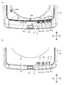
図3(a)は蓋体を開いたときの操作パネルの平面図、図3(b)は蓋体を閉じたときの操作パネルの平面図である。
図3(a)に示すように、操作パネル6は、押圧操作式の操作部61と、運転状態の表示などを行う表示部62と、蓋体3を開ける際に操作される押圧操作式のプッシュボタン63を有している。
FIG. 3A is a plan view of the operation panel when the lid is opened, and FIG. 3B is a plan view of the operation panel when the lid is closed.
As shown in FIG. 3A, the
操作部61は、電源ボタン61a、スタート/一時停止ボタン61b、水量追加ボタン61c(第1操作部)、水流切替ボタン61d(第2操作部)、マニュアル設定ボタン61eなどで構成されている。電源ボタン61a、スタート/一時停止ボタン61b、水量追加ボタン61cおよび水流切替ボタン61dは、トップカバー25の前端上面において、プッシュボタン63の図示右側に横一列に並んで配置されている。
The
電源ボタン61aは、洗濯機1の電源の入り/切りを行うものである。スタート/一時停止ボタン61bは、運転の開始/一時停止を行うものである。水量追加ボタン61cは、洗い工程およびすすぎ工程において、洗濯槽4内の水量を増やす場合に操作されるものである。水流切替ボタン61dは、洗い工程およびすすぎ工程において、洗濯槽4内の洗濯物を洗濯する際の洗濯強さ(洗いの強さ、すすぎの強さ)を変更する場合に操作されるものである。
The
表示部62は、7セグメント式のものであり、残時間/水量表示部62a、洗い時間表示部62b、すすぎ回数表示部62cおよび脱水時間表示部62dが横一列に電源ボタン61a、スタート/一時停止ボタン61b、水量追加ボタン61cおよび水流切替ボタン61dの後方に並んで配置されている。
The
また、プッシュボタン63は、電源ボタン61a、スタート/一時停止ボタン61b、水量追加ボタン61cおよび水流切替ボタン61dの並び方向の図示左側に配置されている。マニュアル設定ボタン61eは、電源ボタン61a、スタート/一時停止ボタン61b、水量追加ボタン61cおよび水流切替ボタン61dの後方側(奥側)に配置されている。
Further, the
また、トップカバー25には、操作パネル6と開口25aとの間の最も狭い位置に突起部31が挿入される挿入溝25eが形成されている。この挿入溝25eは、上側の面と開口25a側の面とが解放する形状を有している。
The
図3(b)に示すように、蓋体3を閉じると、蓋体3の前端縁部3cが操作パネル6の一部である表示部62およびマニュアル設定ボタン61eと重なるようになっている。また、前端縁部3cには、表示部62に対応する位置に、切欠窓3f,3g,3h,3iが形成されている。これにより、蓋体3を閉じた状態で、切欠窓3f,3g,3h,3iを通して、残時間/水量、洗い時間、すすぎ回数、脱水時間を確認できるようになっている。
As shown in FIG. 3B, when the
図4は、本実施形態に係る洗濯機において蓋体を閉じたときの斜視図である。
図4に示すように、蓋体3を閉じたときに、透明窓部3bを通して洗濯槽4内を視認できるようになっている。よって、ユーザは、運転中に水量追加ボタン61cを押すことで、洗濯槽4内の水量を確認しながら給水することができるようになっている。また、水量追加ボタン61cを押すと、清水(洗濯水)が洗剤類投入ケース8の下方から洗濯槽4内に向けて所定の幅で供給されるようになっている。
FIG. 4 is a perspective view when the lid is closed in the washing machine according to the present embodiment.
As shown in FIG. 4, when the
図5は、図4のI−I線における斜視断面図、図6は、プッシュボタン操作後の状態を示す斜視断面図、図7は、蓋体の動作を説明する模式図を示し、(a)はプッシュボタンを押す前の状態、(b)はプッシュボタンを押している状態、(c)はプッシュボタンを離した状態である。なお、本実施形態では、蓋体3がトップカバー25にロックされる機構ではなく、プッシュボタン63を押すことで、蓋体3と操作パネル6(トップカバー25)との間に手を掛ける程度の隙間を形成されるものである。
5 is a perspective sectional view taken along the line II in FIG. 4, FIG. 6 is a perspective sectional view showing a state after the push button is operated, and FIG. 7 is a schematic diagram for explaining the operation of the lid. ) Is a state before the push button is pressed, (b) is a state where the push button is pressed, and (c) is a state where the push button is released. In the present embodiment, the
図5に示すように、プッシュボタン63は、ユーザが指で押して操作されるボタン部63aと、このボタン部63aから挿入溝25e側に向けて延びる腕部63bと、を有して構成されている。
As shown in FIG. 5, the
トップカバー25内には、回動部71と、押上げ部72と、コイルばね73と、収容部74と、が設けられている。
In the
回動部71は、シーソー支持部71aを有し、一端71bが腕部63bと当接し、他端71cがコイルばね73の下端部に当接している。シーソー支持部71aは、収容部74内において軸71dを支点として回動自在に支持されている。また、シーソー支持部71aには、軸71dから上方に延びるとともに先端(上端)が押上げ部72に向けて突出するフック部71eが形成されている。
The rotating
押上げ部72は、コイルばね73が下方から挿入されて収容される凹部72aを有している。凹部72aの上端部には、フック部71eに引っ掛かる引掛突起72bが形成されている。また、押上げ部72には、フック部71e側の面に窪み部72cが形成されている。図5に示すように蓋体3が閉じられた状態では、蓋体3の突起部31が挿入溝25e内に挿入され、押上げ部72がフック部71eに係合してロックされている。
The push-up
図6に示すように、図5に示す状態において、プッシュボタン63を押すことにより、腕部63bがシーソー支持部71aの一端71bを押し下げ、フック部71eが押上げ部72から離れる方向に回動することで、フック部71eと引掛突起72bとの引っ掛かり状態が解除される。これにより、押上げ部72がコイルばね73の弾性復帰力によって押し上げられることで、突起部31が押し上げられ、蓋体3と操作パネル6(トップカバー25)との間に所定の隙間Sが形成される。この隙間Sは、ユーザが手を挿入して蓋体3に手を掛けることができる寸法(例えば、30mm)に設定される。
As shown in FIG. 6, in the state shown in FIG. 5, when the
さらに説明すると、図7(a)に示すように、蓋体3の先端に作用する力F1は、蓋体3を開方向に付勢する付勢部材3sによる力F2よりも大きくなるように設定されている。このため、蓋体3は、力F2に打ち勝って、閉じた状態を維持する。そして、図7(b)に示すように、プッシュボタン63が押されると、フック部71eが軸71dを支点として矢印A方向に回動することで、押上げ部72のロックが解除され、押上げ部72が矢印B方向に押し上げられるとともに、蓋体3が押し上げられる。そして、図7(c)に示すように、コイルばね73の弾性復帰力によってシーソー支持部71aの他端71cが矢印C方向に押されることで、フック部71eが矢印D方向に動作して窪み部72cに入り込み、プッシュボタン63が初期状態に復帰する。
More specifically, as shown in FIG. 7A, the force F1 acting on the tip of the
このように、蓋体3の突起部31がトップカバー25側にロックされる機構ではないので、仮にトップカバー25側の機構が壊れたとしても、蓋体3が開かなくなるといった不都合を防止することができる。
Thus, since the
図8は、本実施形態に係る洗濯機の制御装置を示すブロック図である。
図8に示すように、制御部7は、CPU(Central Processing Unit)、制御プログラムを記憶したROM(Read Only Memory)、RAM(Random Access Memory)等を搭載したCPUボード、入出力インターフェースボード等を搭載し、水量追加ボタン61cの操作に基づいて給水電磁弁5を制御し、また水流切替ボタン61dの操作に基づいて駆動装置45を制御して回転翼43を制御する。また、制御部7は、水量追加ボタン61cが操作されて、増加した水量を水位センサ50の検出値から算出する。
FIG. 8 is a block diagram illustrating the control device for the washing machine according to the present embodiment.
As shown in FIG. 8, the
また、制御部7は、水流切替ボタン61dの操作に基づいて表示部62の残時間/水量表示部62aを制御する。すなわち、水流切替ボタン61dを操作して水流(洗いの強度、すすぎの強度)を切り替えることにより、水流(洗濯強さ)を段階的に設定できるようになっている。
Further, the
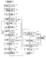
次に、本実施形態に係る洗濯機の制御動作について図9(適宜、図1、図2)を参照して説明する。図9は、本実施形態の洗濯機の制御処理プログラムの一例を示すフローチャートである。
まず、制御部7は、電源ボタン61a(図2参照)が押されて電源が投入されると起動し、例えば、図9に示す洗濯の基本的な制御処理プログラムを実行する。そして、制御部7は、洗濯機1の状態確認および初期設定を行う。そして、制御部7は、操作パネル6の表示部62を点灯し、操作部61からの指示入力にしたがって洗濯コースを設定する。指示入力がない状態では、標準の洗濯コースまたは前回実施の洗濯コースを自動的に設定する。
Next, the control operation of the washing machine according to the present embodiment will be described with reference to FIG. 9 (FIGS. 1 and 2 as appropriate). FIG. 9 is a flowchart illustrating an example of a control processing program of the washing machine according to the present embodiment.
First, the
そして、制御部7は、スタート/一時停止ボタン61bからのスタート信号を取得すると、ステップS1において、布量センシングを実行する。具体的には、駆動装置45によって、洗濯物9(図1参照)が収容された回転翼43を回転させて、電動機45aに通電される電流の大きさの大小で、洗濯物9の重さ(量)を検知し、量のランク分けを行う。
Then, when the
ステップS2において、制御部7は、洗い工程における水量の初期値および水流の初期値、すすぎ工程における水量および水流の初期値を設定する。各初期値は、布量センシング(S1)によって得られた布量(負荷量)に基づいて決定される。
In step S2, the
ステップS3において、制御部7は、洗い工程を開始する。この洗い工程では、給水電磁弁5が開弁されることで、洗剤を含む洗濯水が、ステップS2で設定された水量(初期値)に基づいて洗濯槽4に供給される。その後、駆動装置45によって回転翼43が動作することで、洗濯槽4内の洗濯物9が攪拌される。
In step S3, the
ステップS4において、制御部7は、水量追加ボタン61cがONされたか(押されたか)否かを判定する。ステップS4において、水量追加ボタン61cがONの場合には(Yes)、ステップS5に進み、水量追加ボタン61cがOFF(押されていない)の場合には(No)、ステップS9に進む。
In step S4, the
ステップS5において、制御部7は、水量(水位)が上限値であるか否かを判定する。なお、水量は、水位センサ50から得られる検出値によって判定することができる。ステップS5において、水量が上限値である場合には(Yes)、ステップS9に進み、水量が上限値でない場合には(No)、ステップS6に進む。これにより、洗濯槽4に給水が無駄に行われるのを防止できる。
In step S5, the
ステップS6において、制御部7は、給水電磁弁5を開弁する。これにより、洗濯槽4内に給水が行われ、洗濯槽4内の水量(水位)が増加する。
In step S <b> 6, the
ステップS7において、制御部7は、水量追加ボタン61cがOFFされたか(押されていないか)否かを判定する。ステップS7において、水量追加ボタン61cがOFFの場合には(Yes)、ステップS8に進み、水量追加ボタン61cがOFFではなく、ONのままの場合には(No)、ステップS5に戻る。
In step S7, the
ステップS8において、制御部7は、給水電磁弁5を閉弁する。これにより、洗濯槽4内への給水が停止する。このように、本実施形態では、水量追加ボタン61cを押している間、継続して給水されるようになっている。
In step S8, the
ステップS9において、制御部7は、水流切替ボタン61dがONされたか(押されたか)否かを判定する。ステップS9において、水流切替ボタン61dがONの場合には(Yes)、ステップS10に進み、水流切替ボタン61dがOFFの場合には(No)、ステップS11に進む。
In step S9, the
ステップS10において、制御部7は、水流の変更が実行される。水流の変更では、例えば、回転翼43の回転速度などが変更され、洗濯物9を攪拌する際の強さが変更される。
In step S <b> 10, the
ステップS11において、制御部7は、洗い工程が終了したか否かを判定する。ステップS11において、洗い工程が終了した場合には(Yes)、ステップS12に進み、洗い工程が終了していない場合には(No)、ステップS4に戻る。洗い工程の終了は、例えば、予め設定された所定時間が経過したか否かによって判定できる。
In step S11, the
ステップS12において、制御部7は、すすぎ工程を開始する。このすすぎ工程では、まず、排水と脱水が行われる。
In step S12, the
ステップS13において、制御部7は、洗い工程(S3〜S11)において、水流が変更されたか否かを判定する。ステップS13において、水流が変更された場合には(Yes)、ステップS14に進み、水流が変更されていない場合には(No)、ステップS15に進む。
In step S13, the
ステップS14において(水流変更有り)、制御部7は、変更後の水流(複数回押した場合に最後に設定された水流)に応じた強さ(水流)に設定する。
In step S14 (the water flow is changed), the
ステップS15において(水流変更無し)、制御部7は、ステップS2で設定された初期値のままの強さ(水流)を設定する。
In step S15 (no change in water flow), the
すなわち、洗い工程において、水流切替ボタン61dを押して、水流を強くまたは弱くした場合には、その強さに応じて、すすぎ工程での強さ(水流)を決定する。このように洗い工程で水流を変更した場合には、すすぎ工程での水流が自動的に変更される。
That is, in the washing step, when the water
ステップS16において、制御部7は、すすぎ工程が終了したか否かを判定する。ステップS16において、すすぎ工程が終了した場合には(Yes)、ステップS17に進み、すすぎ工程が終了していない場合には(No)、ステップS16を繰り返す。すすぎ工程の終了は、例えば、予め設定されたすすぎ回数が終了したか否かによって判定される。
In step S16, the
ステップS17において、制御部7は、脱水工程を実行する。脱水工程では、すすぎ工程でのすすぎ水を排水後、排水弁42bを開いた状態で、内槽41と回転翼43とを一体に高速回転させ、洗濯物9に遠心力を加え、遠心脱水する。
In step S <b> 17, the
図10は、回転翼の動作パターンを示す図、図11は、水流切替ボタンを操作したときの表示例である。図10および図11に示すものは、一例であって、本実施形態に限定されるものではない。
図10では、負荷量が半負荷未満と半負荷以上の2つにランク分けされている場合を例に挙げて説明する。なお、半負荷とは、定格負荷の半分(1/2)を意味する(例えば、定格容量が10kgであれば5kg)。また、「回転翼回転速度」は、洗い工程やすすぎ工程における回転翼43の回転速度である。「加速率」は、回転翼43の回転させる際の加速率であり、事前の試験などに基づいて決定される。「回転時限」は、回転翼43を正逆反転させる際のON時間とOFF時間である。ここでは、No.1〜No.7の7段階に設定されており、No.1において水流(強さ)が最も強く、No.7において水流(洗濯強さ)が最も弱く、No.1からNo.7に向けて、水流が徐々に弱くなるように設定されている。なお、7段階に限定されるものではなく、3段階や5段階など適宜変更することができる。
FIG. 10 is a diagram illustrating an operation pattern of the rotor blades, and FIG. 11 is a display example when the water flow switching button is operated. What is shown in FIG. 10 and FIG. 11 is an example, and is not limited to the present embodiment.
In FIG. 10, a case where the load amount is classified into two, that is, less than half load and more than half load will be described as an example. The half load means half (1/2) of the rated load (for example, 5 kg if the rated capacity is 10 kg). The “rotary blade rotation speed” is the rotation speed of the
「半負荷未満」では、No.4に初期値(デフォルト)が設定され、「半負荷以上」では、No.3に初期値(デフォルト)が設定されている。また、半負荷未満と半負荷以上のそれぞれにおいて、初期値(デフォルト)と、初期値より1段階強い「+1」と、初期値より2段階強い「+2」と、初期値より1段階弱い「−1」と、初期値より2段階弱い「−2」と、の5段階に移行できるように構成されている。 For “less than half load”, no. 4 is set to the initial value (default). 3 is set to an initial value (default). Also, in each of less than half load and more than half load, the initial value (default), “+1” that is one step stronger than the initial value, “+2” that is two steps stronger than the initial value, and “−” that is one step weaker than the initial value “−”. 1 ”and“ −2 ”, which is two steps weaker than the initial value, can be shifted to five steps.
例えば、布量センシング(図9のステップS1)において、「半負荷未満」のランクが設定された場合には、初期値として、No.4に示すように、「回転翼回転速度」として100(r/min)、「加速率」として93(r/min/s)、「回転時限」としてON時間2.4(s:秒)、OFF時間1.5(s:秒)が設定される。このような初期値が設定されている場合、洗い工程において、水流切替ボタン61dが1回押された場合には、No.3(「+1」)に移行し、さらに1回押された場合には、No.2(「+2」)に移行する。さらに、1回押される毎に、No.6(「−2」)、No.5(「−1」)、No.4(デフォルト)、No.3(「+1」)の順番で移行する。なお、「半負荷以上」の場合も、水流切替ボタン61dの操作に応じて回転翼43の回転速度などが変更される。
For example, when the rank “less than half load” is set in the cloth amount sensing (step S1 in FIG. 9), the initial value is No. As shown in FIG. 4, the “rotary blade rotation speed” is 100 (r / min), the “acceleration rate” is 93 (r / min / s), the “rotation time limit” is the ON time 2.4 (s: seconds), An OFF time of 1.5 (s: seconds) is set. When such an initial value is set, when the water
また、図11に示すように、表示部62の残時間/水量表示部62aには、初期値の場合には、「0」が表示され、水流切替ボタン61dが1回押されると、残時間/水量表示部62aの表示が「0」から「1」に切り替わり、さらに1回押されると、「1」から「2」に切り替わる。さらに、水流切替ボタン61dが押される毎に、「−2」→「−1」→「0」→「+1」のように切り替わる。このように、残時間/水量表示部62aの表示が切り替わることにより、水流が変化したことを確認することができる。また、透明窓部3bを通して洗濯槽4内の洗濯物9の動きを確認しながら、水流切替ボタン61dを操作することで、水流の強さを直観的に確認することができる。
In addition, as shown in FIG. 11, the remaining time / water
以上説明したように、本実施形態の洗濯機1では、蓋体3に洗濯槽4内を視認可能な透明窓部3bが形成され、給水電磁弁5から給水することで洗濯槽4内の水量を増加させる水量追加ボタン61cが備えられ、制御部7が洗い工程およびすすぎ工程において、水量追加ボタン61cを操作している間、継続して給水電磁弁5から給水するものである。これによれば、ユーザは、透明窓部3bを通して洗濯槽4の水量を確認しながら給水できるので、ユーザが望む水量に直観的に変更することができ、ユーザが望む設定内容に容易に変更することが可能になる。
As described above, in the
また、本実施形態では、水流を変更する水流切替ボタン61dが備えられ、制御部7が洗い工程において水流切替ボタン61dを操作して水流を運転開始時の初期値から変更した場合、すすぎ工程の水流の初期値から変更後の水流に対応した強さ(水流)に自動的に変更する。これによれば、すすぎ工程において再度、水流の強さを設定する必要がなくなるので、操作性を向上できる。
Moreover, in this embodiment, the water
また、本実施形態では、制御部7が洗濯槽4を一時停止させずに水量および水流を変更する。これによれば、洗濯物9が動いている状態において、水量を変更することで洗濯物9の水の浸かり具合、水流を変更することで水流の強さを容易に確認することができる。
Moreover, in this embodiment, the
また、本実施形態では、水流は、少なくとも回転翼43の回転速度によって設定される。これによれば、回転翼43の回転速度を変更することで、水流(洗濯強さ)を容易に変更することができる。
In the present embodiment, the water flow is set at least by the rotational speed of the
また、本実施形態では、筺体2が押圧操作することで蓋体3を開方向に動作させるプッシュボタン63を備える。これによれば、蓋体3には、突起形状の部材(突起部31)を形成すればよいので、透明窓部3bを大型化することが可能になり、ユーザが洗濯槽4内を確認し易くなる。
Further, in the present embodiment, a
なお、本発明は、前記した実施形態に限定されるものではなく、本発明の趣旨を逸脱しない範囲において適宜変更可能である。例えば、本実施形態では、洗い工程のみにおいて水量を増加させる場合を例に挙げて説明したが、洗い工程とすすぎ工程の双方において、水量を増加させる構成を備えていてもよく、すすぎ工程のみにおいて水量を増加させる構成を備えていてもよい。 The present invention is not limited to the above-described embodiment, and can be appropriately changed without departing from the spirit of the present invention. For example, in the present embodiment, the case where the amount of water is increased only in the washing step has been described as an example, but it may be configured to increase the amount of water in both the washing step and the rinsing step, and only in the rinsing step. A configuration for increasing the amount of water may be provided.
1 洗濯機
2 筺体
3 蓋体(蓋)
3b 透明窓部(透明部)
4 洗濯槽
5 給水電磁弁(給水手段)
6 操作パネル
7 制御部
9 洗濯物
25a 開口
41 内槽
42 外槽
43 回転翼
61c 水量追加ボタン(第1操作部)
61d 水流切替ボタン(第2操作部)
63 プッシュボタン
1
3b Transparent window (transparent part)
4
6
61d Water flow switching button (second operation part)
63 Push button
Claims (5)
前記洗濯槽内の底部に設けられる回転翼と、
前記筺体の上部に回動自在に設けられ、前記洗濯槽に対して洗濯物を出し入れする際に開閉される、透明な板を有する蓋と、
前記洗濯槽に給水する給水手段と、
前記回転翼および前記給水手段を制御するとともに、少なくとも洗い工程、すすぎ工程および脱水工程を実行する制御部と、を備え、
前記蓋は、前記洗濯槽内を視認可能な透明部を前記透明な板として有し、
前記筺体は、前記給水手段から給水することで前記洗濯槽内の水量を増加させる押圧式の第1操作部と、前記洗濯槽内の水流を変更する第2操作部と、を備え、
前記制御部は、運転開始後の前記洗い工程および前記すすぎ工程の少なくとも一方の工程において、前記第1操作部を押して操作している間、継続して前記給水手段から給水し、かつ、前記洗い工程において前記第2操作部を操作して前記水流を運転開始時の初期値から変更した場合、変更後に行われる前記すすぎ工程における前記水流を、変更後の前記水流に対応した値に自動的に変更することを特徴とする洗濯機。 A washing tub provided in the housing;
A rotor blade provided at the bottom of the washing tub;
A lid having a transparent plate, which is pivotally provided at the top of the housing and is opened and closed when the laundry is taken in and out of the washing tub;
Water supply means for supplying water to the washing tub;
A controller that controls the rotor blades and the water supply means, and executes at least a washing process, a rinsing process, and a dehydrating process,
The lid, the front Symbol washing tub has a transparent portion visible as the transparent plate,
The housing includes a first operation unit that is a pressing type that increases the amount of water in the washing tub by supplying water from the water supply means, and a second operation unit that changes a water flow in the washing tub .
The control unit continuously supplies water from the water supply means while pressing and operating the first operation unit in at least one of the washing step and the rinsing step after the start of operation , and the washing When the water flow is changed from the initial value at the start of operation by operating the second operation part in the process, the water flow in the rinsing step performed after the change is automatically set to a value corresponding to the changed water flow. A washing machine characterized by changing .
前記筺体は、押圧操作することで前記突起部を開方向に押し上げるプッシュボタンを備えることを特徴とする請求項1から請求項3のいずれか1項に記載の洗濯機。 The lid has a protrusion formed at the front end of the transparent portion on the back surface of the lid,
The washing machine according to any one of claims 1 to 3 , wherein the housing includes a push button that pushes the protrusion in an opening direction by a pressing operation.
Priority Applications (2)
| Application Number | Priority Date | Filing Date | Title |
|---|---|---|---|
| JP2014148562A JP6069263B2 (en) | 2014-07-22 | 2014-07-22 | Washing machine |
| PCT/JP2015/051002 WO2016013232A1 (en) | 2014-07-22 | 2015-01-16 | Washing machine |
Applications Claiming Priority (1)
| Application Number | Priority Date | Filing Date | Title |
|---|---|---|---|
| JP2014148562A JP6069263B2 (en) | 2014-07-22 | 2014-07-22 | Washing machine |
Publications (3)
| Publication Number | Publication Date |
|---|---|
| JP2016022184A JP2016022184A (en) | 2016-02-08 |
| JP2016022184A5 JP2016022184A5 (en) | 2016-03-17 |
| JP6069263B2 true JP6069263B2 (en) | 2017-02-01 |
Family
ID=55162771
Family Applications (1)
| Application Number | Title | Priority Date | Filing Date |
|---|---|---|---|
| JP2014148562A Active JP6069263B2 (en) | 2014-07-22 | 2014-07-22 | Washing machine |
Country Status (2)
| Country | Link |
|---|---|
| JP (1) | JP6069263B2 (en) |
| WO (1) | WO2016013232A1 (en) |
Family Cites Families (8)
| Publication number | Priority date | Publication date | Assignee | Title |
|---|---|---|---|---|
| JPH0634523B2 (en) * | 1987-04-16 | 1994-05-02 | 日本ビクター株式会社 | Color image high efficiency coding method |
| JPS63206290A (en) * | 1987-10-30 | 1988-08-25 | 株式会社日立製作所 | Full automatic washing machine |
| JPH0551277U (en) * | 1991-12-26 | 1993-07-09 | 三洋電機株式会社 | Washing machine |
| JPH0775697A (en) * | 1993-07-14 | 1995-03-20 | Toshiba Corp | Fully automatic washing machine |
| JP3145056B2 (en) * | 1997-05-27 | 2001-03-12 | 株式会社東芝 | Washing machine |
| JP2000042291A (en) * | 1998-07-30 | 2000-02-15 | Hitachi Ltd | Electric washing machine |
| JP4020820B2 (en) * | 2003-04-15 | 2007-12-12 | 松下電器産業株式会社 | Washing and drying machine |
| JP4366229B2 (en) * | 2004-03-31 | 2009-11-18 | 株式会社日立製作所 | Electric washing machine |
-
2014
- 2014-07-22 JP JP2014148562A patent/JP6069263B2/en active Active
-
2015
- 2015-01-16 WO PCT/JP2015/051002 patent/WO2016013232A1/en active Application Filing
Also Published As
| Publication number | Publication date |
|---|---|
| JP2016022184A (en) | 2016-02-08 |
| WO2016013232A1 (en) | 2016-01-28 |
Similar Documents
| Publication | Publication Date | Title |
|---|---|---|
| AU2016306814B2 (en) | Washing machine and control method therefor | |
| AU2019200385B2 (en) | Washing machine and method for controlling same | |
| JP6286662B2 (en) | Washing machine | |
| JP6444645B2 (en) | Drum washing machine | |
| US20150121630A1 (en) | Washing machine and control method thereof | |
| JP6814938B2 (en) | Washing machine | |
| KR20150028006A (en) | Washing apparatus | |
| KR102598167B1 (en) | Washing apparutus and controlling method thereof | |
| KR20160142048A (en) | Washing apparutus and controlling method thereof | |
| KR102047957B1 (en) | Washing machine | |
| JP5987034B2 (en) | Washing machine | |
| JP6069263B2 (en) | Washing machine | |
| JP2013022395A (en) | Twin tub washing machine | |
| JP3983605B2 (en) | Washing machine | |
| KR20100052054A (en) | Washing machine | |
| JP4667160B2 (en) | Washing machine | |
| JP2013103058A (en) | Drum-type washer | |
| JP2013034544A (en) | Washing machine | |
| JP2020103517A (en) | Washing machine | |
| JP4561594B2 (en) | Washing machine | |
| JP2005218662A (en) | Electric washing machine | |
| JP7113212B2 (en) | washing machine | |
| JP7157857B2 (en) | washing machine | |
| KR20100063501A (en) | Laundry machine and controlling method of the same | |
| WO2016197939A1 (en) | Washing machine |
Legal Events
| Date | Code | Title | Description |
|---|---|---|---|
| A521 | Request for written amendment filed |
Free format text: JAPANESE INTERMEDIATE CODE: A523 Effective date: 20151210 |
|
| A871 | Explanation of circumstances concerning accelerated examination |
Free format text: JAPANESE INTERMEDIATE CODE: A871 Effective date: 20151210 |
|
| A975 | Report on accelerated examination |
Free format text: JAPANESE INTERMEDIATE CODE: A971005 Effective date: 20160107 |
|
| A131 | Notification of reasons for refusal |
Free format text: JAPANESE INTERMEDIATE CODE: A131 Effective date: 20160119 |
|
| A521 | Request for written amendment filed |
Free format text: JAPANESE INTERMEDIATE CODE: A523 Effective date: 20160314 |
|
| A02 | Decision of refusal |
Free format text: JAPANESE INTERMEDIATE CODE: A02 Effective date: 20160614 |
|
| A521 | Request for written amendment filed |
Free format text: JAPANESE INTERMEDIATE CODE: A523 Effective date: 20160912 |
|
| A911 | Transfer to examiner for re-examination before appeal (zenchi) |
Free format text: JAPANESE INTERMEDIATE CODE: A911 Effective date: 20160923 |
|
| TRDD | Decision of grant or rejection written | ||
| A01 | Written decision to grant a patent or to grant a registration (utility model) |
Free format text: JAPANESE INTERMEDIATE CODE: A01 Effective date: 20161129 |
|
| A61 | First payment of annual fees (during grant procedure) |
Free format text: JAPANESE INTERMEDIATE CODE: A61 Effective date: 20161226 |
|
| R150 | Certificate of patent or registration of utility model |
Ref document number: 6069263 Country of ref document: JP Free format text: JAPANESE INTERMEDIATE CODE: R150 |
|
| S533 | Written request for registration of change of name |
Free format text: JAPANESE INTERMEDIATE CODE: R313533 |
|
| R350 | Written notification of registration of transfer |
Free format text: JAPANESE INTERMEDIATE CODE: R350 |