JP6066429B2 - Tires with composite cords in the tread - Google Patents
Tires with composite cords in the tread Download PDFInfo
- Publication number
- JP6066429B2 JP6066429B2 JP2014510778A JP2014510778A JP6066429B2 JP 6066429 B2 JP6066429 B2 JP 6066429B2 JP 2014510778 A JP2014510778 A JP 2014510778A JP 2014510778 A JP2014510778 A JP 2014510778A JP 6066429 B2 JP6066429 B2 JP 6066429B2
- Authority
- JP
- Japan
- Prior art keywords
- elastomer
- tread
- styrene
- thermoplastic
- tire according
- Prior art date
- Legal status (The legal status is an assumption and is not a legal conclusion. Google has not performed a legal analysis and makes no representation as to the accuracy of the status listed.)
- Expired - Fee Related
Links
Images


Classifications
-
- D—TEXTILES; PAPER
- D04—BRAIDING; LACE-MAKING; KNITTING; TRIMMINGS; NON-WOVEN FABRICS
- D04C—BRAIDING OR MANUFACTURE OF LACE, INCLUDING BOBBIN-NET OR CARBONISED LACE; BRAIDING MACHINES; BRAID; LACE
- D04C1/00—Braid or lace, e.g. pillow-lace; Processes for the manufacture thereof
- D04C1/06—Braid or lace serving particular purposes
- D04C1/12—Cords, lines, or tows
-
- B—PERFORMING OPERATIONS; TRANSPORTING
- B29—WORKING OF PLASTICS; WORKING OF SUBSTANCES IN A PLASTIC STATE IN GENERAL
- B29D—PRODUCING PARTICULAR ARTICLES FROM PLASTICS OR FROM SUBSTANCES IN A PLASTIC STATE
- B29D30/00—Producing pneumatic or solid tyres or parts thereof
- B29D30/06—Pneumatic tyres or parts thereof (e.g. produced by casting, moulding, compression moulding, injection moulding, centrifugal casting)
- B29D30/52—Unvulcanised treads, e.g. on used tyres; Retreading
-
- B—PERFORMING OPERATIONS; TRANSPORTING
- B60—VEHICLES IN GENERAL
- B60C—VEHICLE TYRES; TYRE INFLATION; TYRE CHANGING; CONNECTING VALVES TO INFLATABLE ELASTIC BODIES IN GENERAL; DEVICES OR ARRANGEMENTS RELATED TO TYRES
- B60C11/00—Tyre tread bands; Tread patterns; Anti-skid inserts
- B60C11/02—Replaceable treads
-
- B—PERFORMING OPERATIONS; TRANSPORTING
- B60—VEHICLES IN GENERAL
- B60C—VEHICLE TYRES; TYRE INFLATION; TYRE CHANGING; CONNECTING VALVES TO INFLATABLE ELASTIC BODIES IN GENERAL; DEVICES OR ARRANGEMENTS RELATED TO TYRES
- B60C11/00—Tyre tread bands; Tread patterns; Anti-skid inserts
- B60C11/14—Anti-skid inserts, e.g. vulcanised into the tread band
-
- B—PERFORMING OPERATIONS; TRANSPORTING
- B60—VEHICLES IN GENERAL
- B60C—VEHICLE TYRES; TYRE INFLATION; TYRE CHANGING; CONNECTING VALVES TO INFLATABLE ELASTIC BODIES IN GENERAL; DEVICES OR ARRANGEMENTS RELATED TO TYRES
- B60C9/00—Reinforcements or ply arrangement of pneumatic tyres
- B60C9/0042—Reinforcements made of synthetic materials
-
- B—PERFORMING OPERATIONS; TRANSPORTING
- B60—VEHICLES IN GENERAL
- B60C—VEHICLE TYRES; TYRE INFLATION; TYRE CHANGING; CONNECTING VALVES TO INFLATABLE ELASTIC BODIES IN GENERAL; DEVICES OR ARRANGEMENTS RELATED TO TYRES
- B60C9/00—Reinforcements or ply arrangement of pneumatic tyres
- B60C9/18—Structure or arrangement of belts or breakers, crown-reinforcing or cushioning layers
-
- C—CHEMISTRY; METALLURGY
- C08—ORGANIC MACROMOLECULAR COMPOUNDS; THEIR PREPARATION OR CHEMICAL WORKING-UP; COMPOSITIONS BASED THEREON
- C08K—Use of inorganic or non-macromolecular organic substances as compounding ingredients
- C08K3/00—Use of inorganic substances as compounding ingredients
- C08K3/34—Silicon-containing compounds
- C08K3/36—Silica
-
- D—TEXTILES; PAPER
- D02—YARNS; MECHANICAL FINISHING OF YARNS OR ROPES; WARPING OR BEAMING
- D02G—CRIMPING OR CURLING FIBRES, FILAMENTS, THREADS, OR YARNS; YARNS OR THREADS
- D02G3/00—Yarns or threads, e.g. fancy yarns; Processes or apparatus for the production thereof, not otherwise provided for
- D02G3/44—Yarns or threads characterised by the purpose for which they are designed
- D02G3/48—Tyre cords
-
- B—PERFORMING OPERATIONS; TRANSPORTING
- B29—WORKING OF PLASTICS; WORKING OF SUBSTANCES IN A PLASTIC STATE IN GENERAL
- B29D—PRODUCING PARTICULAR ARTICLES FROM PLASTICS OR FROM SUBSTANCES IN A PLASTIC STATE
- B29D30/00—Producing pneumatic or solid tyres or parts thereof
- B29D30/06—Pneumatic tyres or parts thereof (e.g. produced by casting, moulding, compression moulding, injection moulding, centrifugal casting)
- B29D30/38—Textile inserts, e.g. cord or canvas layers, for tyres; Treatment of inserts prior to building the tyre
- B29D2030/381—Textile inserts, e.g. cord or canvas layers, for tyres; Treatment of inserts prior to building the tyre the inserts incorporating reinforcing parallel cords; manufacture thereof
-
- C—CHEMISTRY; METALLURGY
- C08—ORGANIC MACROMOLECULAR COMPOUNDS; THEIR PREPARATION OR CHEMICAL WORKING-UP; COMPOSITIONS BASED THEREON
- C08K—Use of inorganic or non-macromolecular organic substances as compounding ingredients
- C08K3/00—Use of inorganic substances as compounding ingredients
- C08K3/02—Elements
- C08K3/04—Carbon
-
- C—CHEMISTRY; METALLURGY
- C08—ORGANIC MACROMOLECULAR COMPOUNDS; THEIR PREPARATION OR CHEMICAL WORKING-UP; COMPOSITIONS BASED THEREON
- C08K—Use of inorganic or non-macromolecular organic substances as compounding ingredients
- C08K7/00—Use of ingredients characterised by shape
- C08K7/02—Fibres or whiskers
Landscapes
- Engineering & Computer Science (AREA)
- Mechanical Engineering (AREA)
- Textile Engineering (AREA)
- Chemical & Material Sciences (AREA)
- Manufacturing & Machinery (AREA)
- Health & Medical Sciences (AREA)
- Chemical Kinetics & Catalysis (AREA)
- Medicinal Chemistry (AREA)
- Polymers & Plastics (AREA)
- Organic Chemistry (AREA)
- Compositions Of Macromolecular Compounds (AREA)
- Ropes Or Cables (AREA)
Description
本発明は、空気式タイヤ、さらに詳細には、そのトレッドが再溝付け用(regrooving)複合コードを組込んでいる空気式タイヤに関する。 The present invention relates to a pneumatic tire, and more particularly to a pneumatic tire whose tread incorporates a regrooving composite cord.
多くの場合、大型車両用の空気式タイヤにおけるトレッドパターンは、直線形、ジグザク形または波形の周辺溝を有しており、これらの溝は、横方向の溝および/または切込みによって連結することが可能である。これらの周辺溝は、一般に、磨耗標識を含み、これらの標識は、これらの溝の底部を一定の周辺長に亘って覆っている加硫ゴム混合物の小プラットフォームである;上記標識は、使用中のトレッド上に法的に残存しなければならない最低のパターン深を表示する。大型車両用のパターンは、再溝付け(新たな溝を再度くりぬくことができる作業)可能であり、そのようなパターンを有する空気式タイヤは、その側壁上に、表示“Regroovable (再溝付け可能)”または符号“U”を付している。再溝付けは、一方では大型車両空気式タイヤのグリップ力を延命し、他方では、タイヤ寿命(キロメートルで表す)を有意に(場合によって、15%〜30%)増大させることを可能にする;このことは、再トレッド形成の実施可能性を損なうことなく達成され、さらにまた、このことは、大型車両空気式タイヤの本質的な特徴でもある。また、再溝付けは、燃料節減を可能にすることも付け加えなければならない;空気式タイヤは、新品状態においては最高再溝付け深に相当する総パターン深を有する空気式タイヤの転がり抵抗性と比較して、初期状態の溝深の低下の結果として低めの転がり抵抗性を示す。 In many cases, the tread pattern in pneumatic tires for heavy vehicles has straight, zigzag or corrugated peripheral grooves, which can be connected by lateral grooves and / or notches. Is possible. These peripheral grooves generally contain wear markings, which are small platforms of vulcanized rubber mixture covering the bottom of these grooves over a certain peripheral length; The minimum pattern depth that must legally remain on the tread of Patterns for heavy vehicles can be re-grooved (operations that can re-drill new grooves), and pneumatic tires with such patterns can be marked “Regroovable” on their sidewalls. ) ”Or“ U ”. Regrooving, on the one hand, prolongs the grip of heavy vehicle pneumatic tires and on the other hand makes it possible to significantly (in some cases 15% to 30%) increase tire life (expressed in kilometers); This is accomplished without compromising the feasibility of re-treading, which is also an essential feature of heavy vehicle pneumatic tires. In addition, regrooving must also allow for fuel savings; pneumatic tires have the rolling resistance of pneumatic tires with a total pattern depth corresponding to the maximum regrooving depth in the new state. In comparison, a lower rolling resistance is exhibited as a result of a decrease in the groove depth in the initial state.
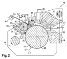
それ自体知られている通り、溝の再溝付けは、多くの場合作業者によって取扱われる円形の加熱ブレードを使用して実施し得る。このブレードは、トレッド表面上に支持されているフレームに連結して、手作業によって、トレッド表面上の溝の線を直線に従ってない溝の場合でさえも信頼性高く追跡するように使用し得る。しかしながら、この再溝付け作業は、多くの予防措置を必要とする。これらの予防措置のうちの第1は、再溝付け作業を、約2mmの溝深が残存しているときに実施することからなる;この深さは、トレッド表面と溝底部に置かれた磨耗標識の半径方向外側表面間で測定する。この予防措置は、パターンデザインを容易に可視化し、ひいてはパターンデザインを大きな困難もなく再現することを可能にする。残存パターン深および空気式タイヤの製造業者が推奨する再溝付け深さを知ることによって、再溝付け用ブレードの高さを調整し設定することが可能である。 As is known per se, the regrooving of the groove can be carried out using a circular heating blade which is often handled by the operator. This blade can be used in conjunction with a frame supported on the tread surface to reliably track the line of grooves on the tread surface even in the case of grooves that do not follow a straight line. However, this regrooving operation requires a number of precautions. The first of these precautions consists of performing the regrooving operation when a groove depth of approximately 2 mm remains; this depth is the wear placed on the tread surface and the groove bottom. Measure between the radially outer surfaces of the sign. This precaution makes it easy to visualize the pattern design and thus reproduce it without great difficulty. By knowing the remaining pattern depth and the regrooving depth recommended by the pneumatic tire manufacturer, it is possible to adjust and set the height of the regrooving blade.
一般的に表示されている再溝付け深は、理論的深さである。これらの深さは、多くの場合、満足し得るもので、ブレード高を理論的に設定して、再溝付けした溝底部とクラウン補強材の半径方向上面間にほぼ一定厚のゴムを得ることができるものの、過度に深く再溝付けするリスクは無視し得ない。実際に、過度に強い再溝付けは、損傷を生じさせて、タイヤケーシングの早期の破壊をもたらし得る。また、過度に強い再溝付けは、経済的な再トレッド形成、即ち、トレッドのみを変換する再トレッド形成の可能性も危うくする。また、過度に強い再溝付けは、極端な場合、再溝付け後の新たな溝の底部において、半径方向の下に位置するクラウン補強材のパイルを露出させ得る;このことは、施行中の法制によって一般に許されない。 The commonly indicated regrooving depth is the theoretical depth. These depths are often satisfactory and theoretically set the blade height to obtain a rubber of approximately constant thickness between the re-grooved groove bottom and the radial top surface of the crown reinforcement. However, the risk of regrooving too deep is not negligible. Indeed, excessively strong regrooving can cause damage and lead to premature destruction of the tire casing. Excessively strong regrooving also jeopardizes the possibility of economical re-tread formation, ie re-tread formation that converts only the tread. Also, excessively strong regrooving can, in extreme cases, expose a pile of crown reinforcements located below the radial direction at the bottom of the new groove after regrooving; Not generally allowed by law.
クラウン補強材の半径方向外表面上において空気式タイヤの製造業者が設定した最小厚のゴムの存在に正確に従う再溝付けを実施することを可能にすると共に、タイヤ寿命(キロメートルで表す)をできる限り増大させることを可能にするために、特許US 6 003 576号は、少なくとも1枚のプライの補強用素材から形成されたクラウン補強材が半径方向上に存在するラジアルカーカス補強材と再溝付けし得る溝を設けたトレッドとを含む空気式タイヤにおいて、深さ標識を有する上記再溝付け可能な溝の半径方向下に位置するトレッド部分を設け、各標識が有効な再溝付けのために達すべき最小深さと越える状況にあってはならない最大深さとを表示する少なくとも1つの手段を含むことを推奨している。 Enables re-grooving on the radial outer surface of the crown reinforcement exactly according to the presence of the minimum thickness rubber set by the pneumatic tire manufacturer and allows the tire life (expressed in kilometers) In order to be able to increase as much as possible, the patent US 6 003 576 is re-grooved with a radial carcass reinforcement in which a crown reinforcement formed from a reinforcement material of at least one ply exists radially. In a pneumatic tire including a tread with a groove capable of being provided with a tread portion located radially below the regroovable groove having a depth marking, each marking being for effective regrooving It is recommended to include at least one means for indicating the minimum depth to be reached and the maximum depth that must not be exceeded.
深さ標識は、好ましくは、上記溝の方向に平行して、該方向に垂直にまたはこれら平行および垂直の双方同時に溝底部に配置した小さいがゼロではない幅を有する切込みの形で設け、上記最小および最大深さを表示する上記手段は、その場合、深さ表示切込みを有する幾何学的底部形状である。 The depth indicator is preferably provided in the form of a notch having a small but non-zero width arranged at the bottom of the groove parallel to the direction of the groove and perpendicular to the direction or both parallel and perpendicular at the same time. Said means for displaying the minimum and maximum depth is then a geometric bottom shape with a depth indication cut.
トレッドの再溝付け技術および方法において莫大な進歩をもたらしているものの、上記再溝付け標識は、自動化および広範囲の機器化にもかかわらず、クラウン補強材のプライに極めて近い切抜き用ブレードの通過のリスクを排除していない;これらの標識は、深さ調整における人的存在を排除していない。さらにまた、上記再溝付けは、元の溝の半径方向下で実施され、新たなトレッド厚に応じて設計され、厚さが大いに低減され且つ最適パターンデザインが、必ずしも、標準のトレッド厚において構想されたデザインではないトレッドに応じていない。 Despite tremendous progress in tread regrooving techniques and methods, the regrooving mark, despite automation and extensive instrumentation, is capable of passing a cutting blade very close to a crown reinforcement ply. It does not exclude risk; these markers do not exclude human presence in depth adjustment. Furthermore, the regrooving is performed radially below the original groove, designed according to the new tread thickness, the thickness is greatly reduced and the optimal pattern design is not necessarily envisioned at standard tread thickness. Not adapted to the tread that is not the design.
また、新品空気式タイヤのトレッド内に、このトレッドの内側に縦方向に配置した複数のコードを組込む対策もなされている(US 2 148 343号)。トレッドの磨耗がコードに達すると直ぐに、コードは、遠心力によって排出され、新たな溝がそのようにして形成される。 In addition, measures have been taken to incorporate a plurality of cords arranged in the vertical direction inside the tread of a new pneumatic tire (US 2 148 343). As soon as the tread wear reaches the cord, the cord is discharged by centrifugal force and a new groove is thus formed.
文献EP 1 392 497 B1号は、中間層を内部に含み、その外壁が、子午断面において見られるように、形成すべき再溝付け溝の壁輪郭と同一の輪郭を部分的に有するところのトレッドを提供している。これらの中間層は、トレッドのゴム混合物とは非粘着性である特性を有している。これらの中間層は、空気式タイヤのブランクの成形中に、形成すべき再溝付け溝の材料とトレッドの残余物間にゴム混合物のブリッジを生成させるためのオリフィスを備えている。これらのゴムブリッジは、地面と接触するときのトレッドの磨耗による形成すべき再溝付け溝の材料の排出を阻止すると共に作業者がこれらのゴム混合物のブリッジを破壊することによって抜き出すことを可能にする。
しかしながら、このトレッドの製造方法は、特に、トレッドブランク内に、中間層を、次いで、再溝付け用コードを連続して配置することが必要であることから、長たらしくて、複雑で且つ費用高である。
Document EP 1 392 497 B1 includes a tread in which an intermediate layer is included inside, the outer wall of which has the same contour as the wall contour of the regrooving groove to be formed, as seen in the meridional section. Is provided. These intermediate layers have the property of being non-tacky with the tread rubber mixture. These intermediate layers are provided with orifices to create a rubber mixture bridge between the regrooved groove material to be formed and the tread residue during the molding of a pneumatic tire blank. These rubber bridges prevent the regrooving groove material to be formed due to wear on the tread when in contact with the ground and allow the operator to pull out by breaking these rubber mixture bridges To do.
However, this tread manufacturing method is particularly lengthy, complicated and expensive because it requires the intermediate layer and then the regrooving cord to be placed successively in the tread blank. It is.
以下において、用語“コード”または“ストリング”は、本質的な接触断面を有し且つ他の如何なる寸法よりもはるかに大きい長さを有する製品を意味するものと理解されたい、また、用語“再溝付け用コード”は、製造中の空気式または非空気式タイヤのトレッドの内部空洞内に挿入し、次いで、稼動中のトレッドの磨耗後に、抜き出して周辺再溝付け溝を形成することを意図するコードを意味するものと理解されたい。再溝付け用コードは、トレッド内に挿入後、連続円周環を形成する。この環は、必要に応じて、直線形、ジグザク形または波形であり得る。 In the following, the term “code” or “string” should be understood to mean a product having an intrinsic contact cross section and having a length much greater than any other dimension, and the term “re- The grooving cord is intended to be inserted into the internal cavity of the tread of a pneumatic or non-pneumatic tire being manufactured and then withdrawn to form a peripheral regrooving groove after the tread is worn during operation Should be understood as meaning the code The regrooving cord forms a continuous circumferential ring after being inserted into the tread. The ring can be straight, zigzag or corrugated as desired.
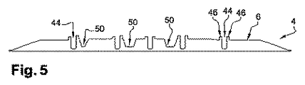
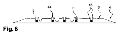
本発明の主題は、トレッドを有する空気式または非空気式タイヤであって、上記トレッドが、少なくとも1つの内部空洞内に、エラストマーコアおよび該エラストマーコアを取囲むシースを含む複合コードを含むことおよび上記シースが、らせん状に絡み合せた不連続繊維から製造した中空円筒状組紐(braid)であることを特徴とする。 The subject of the present invention is a pneumatic or non-pneumatic tire having a tread, the tread comprising a composite cord comprising an elastomer core and a sheath surrounding the elastomer core in at least one internal cavity; The sheath is a hollow cylindrical braid manufactured from discontinuous fibers entangled in a spiral.
上記シースの組紐は、例えば、シースの母線に対してある角度をなして配置した2連の交差状繊維(crisscrossed fibre)から形成する。空き(spacing)が、上記不連続繊維間に残存し、上記シースの組紐に、上記シースのその母線方向の伸びの関数としての特にシース直径の大きな変形性を付与している。また、これらの空きは、上記空気式タイヤのモールド内での加硫中に、上記空気式タイヤのトレッドの空洞内に配置した上記コードのエラストマーコアと上記トレッドの隣接混合物間の直接の接触、ひいては上記複合コードのその周辺全体に亘っての濃密且つ均質な機器的結合をもたらすゴムブリッジの形成を可能にするという利点も有する。 The sheath braid is formed, for example, from two cross-crossed fibers arranged at an angle with respect to the sheath generatrix. Spacing remains between the discontinuous fibers, giving the sheath braid a particularly large sheath diameter deformability as a function of the elongation of the sheath in its generatrix direction. Also, these voids, during vulcanization in the mold of the pneumatic tire, direct contact between the elastomeric core of the cord and the adjacent mixture of the tread disposed in the cavity of the tread of the pneumatic tire, It also has the advantage of allowing the formation of a rubber bridge that results in a dense and homogeneous mechanical connection over the entire periphery of the composite cord.
上記複合コードは、上記エラストマーコアを上記組紐中に注入することによって製造し得、引き続き、空気式タイヤの加硫前に、トレッドの空洞内に容易に組込み得る。別の形態によれば、シースを存在しているエラストマーコアの周りに直接ブレイズすることも可能である。
また、上記組紐は、空気式タイヤの加硫の間、上記エラストマーコアを包囲し、従って、加硫段階全体に亘ってのこのエラストマーコアの形状の維持を容易にするという利点も有する。
The composite cord may be manufactured by injecting the elastomer core into the braid and subsequently easily incorporated into the tread cavity prior to vulcanization of the pneumatic tire. According to another form, it is also possible to blaze directly around the existing elastomer core.
The braid also has the advantage of surrounding the elastomeric core during vulcanization of the pneumatic tire and thus facilitating maintenance of the shape of the elastomeric core throughout the vulcanization stage.
上記複合コードと上記トレッドの隣接材料との機器的結合は、この複合コードが走行中に排出されないために、また、この複合コードのトレッド残余物との何らかの相対運動を阻止するのに十分である;この運動は、摩擦作用、ひいては界面での熱放出の源である。 The mechanical coupling between the composite cord and the adjacent material of the tread is sufficient to prevent the composite cord from being ejected during travel and to prevent any relative movement of the composite cord with the tread residue. This movement is a source of frictional action and thus heat release at the interface.
また、上記ゴムブリッジは、上記複合コードが空気式タイヤのトレッドの磨耗によって目に見えるようになった時点で特定の工具なしで手作業によって取外すことができる、従って、上記複合コードの容易で且つ正確な引抜きを可能にすると共に上記エラストマーコアを完全なままに保つという利点を有する。上記複合コードの引抜きは、トレッドパターン中の再溝付け溝と同様な溝外観をもたらす。上記組紐は、着色して上記複合コードの引抜きに適する磨耗レベルの検知を容易にすることができる。 The rubber bridge can also be removed manually without a specific tool when the composite cord becomes visible due to the wear of the pneumatic tire tread. It has the advantage of allowing accurate withdrawal and keeping the elastomer core intact. Pulling out the composite cord provides a groove appearance similar to a regrooving groove in the tread pattern. The braid can be colored to facilitate detection of a wear level suitable for drawing the composite cord.
第1の実施態様によれば、上記複合コードのエラストマーコアの配合物は、少なくとも1種のジエンエラストマーをベースとする。好ましくは、この組成物はエラストマー100質量部当り30質量部(30phr)よりも多いAで示す充填剤を含み、この充填剤の粒子は500μmよりも小さい平均粒度を有するナノ粒子である。 According to a first embodiment, the composite core elastomer core formulation is based on at least one diene elastomer. Preferably, the composition comprises greater than 30 parts by weight (30 phr) of a filler per 100 parts by weight of elastomer, wherein the filler particles are nanoparticles having an average particle size of less than 500 μm.
もう1つの実施態様によれば、上記複合コードのエラストマーコアは、少なくとも1種の熱可塑性エラストマーをベースとする;該熱可塑性エラストマーは、少なくとも1個の不飽和エラストマーブロックと少なくとも1個の熱可塑性ブロックとを含むブロックコポリマーである。 According to another embodiment, the elastomeric core of the composite cord is based on at least one thermoplastic elastomer; the thermoplastic elastomer comprising at least one unsaturated elastomer block and at least one thermoplastic. A block copolymer containing a block.
本発明の1つの実施態様に従うコードは、その最大寸法が、あらゆる断面において、3mmと20mmの間、好ましくは5mmと15mmの間の寸法であるようなものである。
これらのコード寸法は、これらのコードをトレッドから取出した後、3mmと15mmの間の軸幅を有する溝または畝溝(furrow)を形成することを可能にする;この軸幅は、タイヤのパターンに、降雨地面上を走行するときの優れた排水能力を付与する。
3mmよりも小さいと、コードの能力はもはや十分ではなく、また、15mmよりも大きいと、取入れられる利得はもはや実質的でない。
The cord according to one embodiment of the invention is such that its maximum dimension is between 3 mm and 20 mm, preferably between 5 mm and 15 mm in every cross section.
These cord dimensions make it possible to form grooves or furrows with axial widths between 3 mm and 15 mm after taking these cords out of the tread; In addition, it provides excellent drainage capacity when traveling on rainy ground.
Below 3 mm, the cord capacity is no longer sufficient, and above 15 mm, the gain gained is no longer substantial.
上記複合コードの断面は、任意の形状、特に、実質的に円形、または正方形、または長方形、またはU字形であり得る。 The cross section of the composite cord can be any shape, in particular substantially circular, or square, or rectangular, or U-shaped.
本発明は、特に、バン類、“大型車両”(即ち、地下鉄、バス、重量物道路輸送車(トラック、トラクター、トレーラー)、または農業用車両もしくは土木機器のような道路外車両)、或いは他の輸送または作業用車両から選ばれる産業用車両に装着することを意図する空気式タイヤに関する。また、本発明は、乗用車、SUV (スポーツ用多目的車)、二輪車(特に、オートバイ)、航空機等の空気式タイヤにも該当する。 The invention is particularly applicable to vans, “large vehicles” (ie subways, buses, heavy-duty road transport vehicles (trucks, tractors, trailers), or off-road vehicles such as agricultural vehicles or civil engineering equipment), or others. The present invention relates to a pneumatic tire that is intended to be mounted on an industrial vehicle selected from among transport and work vehicles. The present invention also applies to pneumatic tires such as passenger cars, SUVs (sports multipurpose vehicles), motorcycles (particularly motorcycles), and aircraft.
本発明に従う複合コードは、空気式タイヤ、即ち、空気で膨張させるタイヤにおいて、さらにまた、非空気式タイヤ、即ち、耐荷重性が構造的に且つ非空気的に付与されるタイヤにおいて使用し得る。 The composite cord according to the invention can be used in pneumatic tires, i.e. tires that are inflated with air, and also in non-pneumatic tires, i.e. tires that are structurally and non-pneumatically loaded. .
本説明においては、特に明確に断らない限り、パーセント(%)は、全て質量%である。
さらにまた、“aとbの間”なる表現によって示される値の間隔は、いずれも、aよりも大きくからbよりも小さいまでに及ぶ値の範囲を示し(即ち、限界値aとbを除く)、一方、“a〜b”なる表現によって示される値の間隔は、いずれも、aからbまでに及ぶ値の範囲を意味する(即ち、厳格な限定値aおよびbを含む)。
用語“phr”は、エラストマー100質量部当りの質量部を意味するものと理解されたい。
In this description, unless otherwise specified, all percentages (%) are mass%.
Furthermore, any interval of values indicated by the expression “between a and b” indicates a range of values ranging from greater than a to less than b (ie excluding limit values a and b). ), On the other hand, any interval of values indicated by the expression “a to b” means a range of values ranging from a to b (ie, including strict limits a and b).
The term “phr” is understood to mean parts by weight per 100 parts by weight of elastomer.
“ベースとする組成物”なる表現は、使用する各種構成成分の混合物および/または反応生成物を含む組成物を意味するものと理解されたい;これらベース構成成分のある種のものは、上記組成物の種々の製造段階において、特に、その製造および架橋または加硫中に、少なくとも部分的に互いに反応し得るか或いは反応するように意図する。 The expression “base composition” should be understood as meaning a composition comprising a mixture of various components and / or reaction products used; certain of these base components are In the various production stages of the product, in particular during its production and crosslinking or vulcanization, it is at least partly possible to react with each other or to react.
使用する測定および試験法
充填剤の特性決定
dwで示すナノ粒子の(質量)平均粒度は、通常、水または界面活性剤を含有する水溶液中の分析すべき充填剤の超音波解凝集による分散後に測定する。
Measurements and test methods used
Filler characterization
(weight) average particle size of the nanoparticles indicated by d w is usually measured after dispersion by ultrasonic deagglomeration of the filler to be analyzed in an aqueous solution containing water or surfactant.
シリカのような無機充填剤においては、測定は、Brookhaven Instruments社から販売されている“XDC”(X線ディスク遠心分離) X線検出遠心分離沈降速度計を使用して、以下の手順に従って実施する。40mlの水中の分析すべき無機充填剤の3.2gのサンプルの懸濁液を、1500W超音波プローブ(Bioblock社から販売されている3/4インチ(19.05mm)Vibracellソニケーター)の60%出力(“出力制御”の最高位置の60%)において、8分間継続する作用によって調製する;音波処理後、15mlの上記懸濁液を、上記回転ディスク中に導入する;120分間の沈降後に、粒子の粒度の質量分布および質量平均粒度dwを、上記XDC沈降速度計のソフトウェアによって算出する(dw = Σ(ni×di 5) / Σ(ni×di 4) (niは、サイズまたは直径階級diを有する物体数である)。 For inorganic fillers such as silica, the measurement is carried out according to the following procedure using an “XDC” (X-ray disc centrifuge) X-ray detection centrifuge sedimentation rate meter sold by Brookhaven Instruments. . A suspension of a 3.2 g sample of the inorganic filler to be analyzed in 40 ml of water was transferred to a 60% output (“3/4” (19.05 mm) Vibracell sonicator sold by Bioblock) (“ Prepared by a continuous action for 8 minutes at 60% of the highest position of the “power control”; after sonication, 15 ml of the suspension is introduced into the rotating disk; Mass distribution and mass average particle size d w of the above are calculated by the XDC sedimentation velocity software (d w = Σ (n i × d i 5 ) / Σ (n i × d i 4 ) (n i is the size Or the number of objects having a diameter class d i ).
カーボンブラックにおいては、上記手順を、15%のエタノールと0.05%のノニオン界面活性剤を含む水溶液(容量%)によって実施した。測定は、DCPタイプの遠心分離光沈降速度計(Brookhaven Instruments社から販売されているディスク遠心分離光沈降速度計)を使用して実施する。10mgのカーボンブラックの懸濁液を、前以って、15%のエタノールと0.05%のノニオン界面活性剤を含む40mlの水溶液(容量%)中で、600W超音波プローブ(Bioblock社から販売されているVibracell 1/2インチ(12.7mm)ソニケーター)の60%出力(即ち、“勾配振幅”の最高位置の60%)において、10分間継続する作用によって調製する。音波処理中に、15mlの水(0.05%のノニオン界面活性剤を含む)と1mlのエタノールからなる勾配を、上記沈降速度計の回転ディスク中に、8000回転/分で注入して“段階勾配”形成させる。その後、0.3mlの上記カーボンブラック懸濁液を、上記勾配の表面に注入する;120分間継続する沈降後に、粒度の質量分布および質量平均粒度dwを、上述のようにして、上記沈降速度計のソフトウェアによって算出する。
For carbon black, the above procedure was performed with an aqueous solution (vol%) containing 15% ethanol and 0.05% nonionic surfactant. The measurement is carried out using a DCP-type centrifugal light sedimentation velocimeter (a disk centrifugal light sedimentation velocimeter sold by Brookhaven Instruments). A suspension of 10 mg carbon black was previously prepared in a 40 ml aqueous solution (volume%) containing 15% ethanol and 0.05% nonionic surfactant (600 W ultrasound probe (commercially available from Bioblock). The Vibracell 1/2 inch (12.7 mm) sonicator) is prepared by an action that lasts for 10 minutes at 60% power (
シース
本発明に従う複合コードの第1の本質的特徴は、らせん状に絡み合せた不連続繊維から製造した中空円筒状組紐からなるシースを含むことである。このシースは、上記複合コードのエラストマーコアを包囲している。
Sheath The first essential feature of the composite cord according to the present invention is that it includes a sheath made of a hollow cylindrical braid made of discontinuous fibers intertwined in a spiral. This sheath surrounds the elastomeric core of the composite cord.
上記組紐は、例えば、上記組紐の母線に対してある角度をなして配置した2連の交差状繊維から形成する。上記不連続繊維は、これら繊維の間に、上記組紐のその母線方向の伸びの関数としての特に組紐直径の大きな変形性を上記組紐に付与している空きを形成している。 The braid is formed, for example, from two intersecting fibers arranged at an angle with respect to the busbar of the braid. The discontinuous fibers form a space between the fibers that gives the braid a particularly large braid diameter deformability as a function of the stretch of the braid in its generatrix direction.
また、これらの空きは、上記空気式タイヤトレッドの空洞内の上記コードの加硫中に、上記複合コードのエラストマーコアと上記トレッドの隣接混合物間の直接の接触、ひいては上記複合コードのその周辺全体に亘っての濃密且つ均質な機器的固着を確保するゴムブリッジの形成を可能にするという利点も有する。 Also, these voids are used for direct contact between the elastomeric core of the composite cord and the adjacent mixture of the tread during the vulcanization of the cord in the cavity of the pneumatic tire tread, and thus the entire periphery of the composite cord. It also has the advantage of allowing the formation of a rubber bridge that ensures a dense and homogeneous instrumental adherence.
好ましくは、上記組紐の繊維の形状およびそれら繊維の集成は、上記空きの表面積が上記組紐の表面積の5%と30%の間にあるような形状と集成である。5%よりも低いと、ゴムブリッジ数はトレッド内での上記コードの良好な固着を確保するには不十分となり、30%よりも高いと、特定の工具無しで再溝付け用コードをトレッドから引抜くことが困難になる。極めて好ましくは、上記空きの表面積は、上記組紐の表面積の10%と20%の間である。 Preferably, the shape of the braided fibers and the assembly of the fibers is such that the vacant surface area is between 5% and 30% of the surface area of the braid. Below 5%, the number of rubber bridges is insufficient to ensure good anchoring of the above cords in the tread, and above 30%, regrooving cords can be removed from the tread without specific tools. It becomes difficult to pull out. Most preferably, the free surface area is between 10% and 20% of the surface area of the braid.
これらの組紐は、伸長可能な直径を有する。これらの組紐は、通常、円形または平坦断面を有する熱可塑性モノフィラメントからブレイズする。
好ましくは、上記組紐の繊維は、ポリアミド、ポリエステル、ポリスルホン、ポリ(フェニレンスルフィド)、ポリ(エーテル‐ケトン)、ポリエーテルイミド、ポリ(アミド‐イミド)、ポリイミド、熱可塑性エラストマー、これらの混合物およびこれらの合金(アロイ)からなる群から選ばれる。
These braids have an extensible diameter. These braids usually blaze from thermoplastic monofilaments having a circular or flat cross section.
Preferably, the braided fibers are polyamide, polyester, polysulfone, poly (phenylene sulfide), poly (ether-ketone), polyetherimide, poly (amide-imide), polyimide, thermoplastic elastomer, mixtures thereof and the like Selected from the group consisting of alloys.
ポリアミドは、ポリアミド6、ポリアミド6,6およびこれらの混合物のような脂肪族ポリアミドの群から選らばれる。
また、ポリアミドは、ポリ(メタキシリレン) (MXD‐6)、ポリフタルアミド、コポリアミドおよびこれらの混合物のような半芳香族ポリアミドの群から選ばれる。
The polyamide is selected from the group of aliphatic polyamides such as polyamide 6, polyamide 6,6 and mixtures thereof.
The polyamide is also selected from the group of semi-aromatic polyamides such as poly (metaxylylene) (MXD-6), polyphthalamide, copolyamide and mixtures thereof.
好ましくは、ポリエステルは、ポリエチレンテレフタレート(PET)、ポリブチレンテレフタレート(PBT)、ポリカーボネート(PC)およびポリエチレンナフタレート(PEN)、並びにこれらの混合物から選ばれる。 Preferably, the polyester is selected from polyethylene terephthalate (PET), polybutylene terephthalate (PBT), polycarbonate (PC) and polyethylene naphthalate (PEN), and mixtures thereof.
また、有利には、上記組紐を形成するための繊維としては、ポリ(エーテルブロック‐アミド) (PEBA)、熱可塑性ポリウレタン(TPU)、エーテル‐エステルコポリマー(COPE)およびこれらの混合物の群から選ばれる熱可塑性エラストマーの繊維も選択し得る。
好ましくは、エーテル‐エステルコポリマー(COPE)は、ポリエステル‐エーテルおよびポリエステル‐エステルから選ばれる。
Also advantageously, the fibers for forming the braid are selected from the group of poly (ether block-amide) (PEBA), thermoplastic polyurethane (TPU), ether-ester copolymer (COPE) and mixtures thereof. Thermoplastic elastomer fibers can also be selected.
Preferably, the ether-ester copolymer (COPE) is selected from polyester-ethers and polyester-esters.
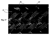
そのような伸長性組紐は、周知であって、商業的に入手可能である。例えば、Gremco社は、ポリアミド6,6モノフィラメントから製造した膨張性編み加工管状組紐をGremflex (登録商標) PA6.6ブランドとして販売している。単対物双眼顕微鏡を使用して観察すれば、上記組紐の所定表面積に対する空きの平均表面積は、容易に判定可能である。この平均値は、この特定の例においては、15%程度である(図17参照)。また、Gremco社は、数ある中でも、PBTポリエステルモノフィラメントから製造した同様な組紐もGremflex (登録商標) FRブランドとして販売している。 Such extensible braids are well known and are commercially available. For example, Gremco sells an expandable knitted tubular braid made from polyamide 6,6 monofilament under the Gremflex® PA6.6 brand. If observed using a single objective binocular microscope, the average surface area of the braid with respect to the predetermined surface area can be easily determined. This average value is about 15% in this specific example (see FIG. 17). Gremco also sells similar braids made from PBT polyester monofilament, among others, under the Gremflex® FR brand.
エラストマーコア
本発明に従う複合コードの第2の本質的特徴は、エラストマーコアを含むことである。
第1の実施態様によれば、このエラストマーコアの組成物は、ジエンエラストマーをベースとする。好ましくは、該組成物は30phrよりも多いAで示す充填剤を含み、この充填剤の粒子は500nmよりも小さい質量平均粒度を有するナノ粒子である。
Elastomeric Core A second essential feature of the composite cord according to the present invention is that it comprises an elastomeric core.
According to a first embodiment, the elastomeric core composition is based on a diene elastomer. Preferably, the composition comprises more than 30 phr of a filler indicated by A, and the particles of the filler are nanoparticles having a weight average particle size of less than 500 nm.
ジエンエラストマー
用語“ジエンエラストマー”または“ジエンゴム”は、知られている通り、ジエンモノマー(2個の共役型または非共役型炭素‐炭素二重結合を担持するモノマー)に少なくとも一部由来するエラストマー(即ち、ホモポリマーまたはコポリマー)を意味するものと理解すべきである。
The diene elastomer term “diene elastomer” or “diene rubber”, as is known, is an elastomer (at least partly derived from a diene monomer (a monomer bearing two conjugated or nonconjugated carbon-carbon double bonds)). I.e. homopolymer or copolymer).
上記エラストマーコアのジエンエラストマーは、好ましくは、ポリブタジエン(BR)、合成ポリイソプレン(IR)、天然ゴム(NR)、ブタジエンコポリマー、イソプレンコポリマーおよびこれらエラストマーの混合物からなる高不飽和ジエンエラストマーの群から選択する。そのようなコポリマーは、さらに好ましくは、ブタジエン/スチレンコポリマー(SBR)、イソプレン/ブタジエンコポリマー(BIR)、イソプレン/スチレンコポリマー(SIR)およびイソプレン/ブタジエン/スチレンコポリマー(SBIR)からなる群から選択する。 The diene elastomer of the elastomer core is preferably selected from the group of highly unsaturated diene elastomers consisting of polybutadiene (BR), synthetic polyisoprene (IR), natural rubber (NR), butadiene copolymer, isoprene copolymer and mixtures of these elastomers. To do. Such copolymer is more preferably selected from the group consisting of butadiene / styrene copolymer (SBR), isoprene / butadiene copolymer (BIR), isoprene / styrene copolymer (SIR) and isoprene / butadiene / styrene copolymer (SBIR).
特に適しているのは、4%と80%の間の1,2‐単位含有量(モル%)を有するポリブジエンまたは80%よりも多いシス‐1,4‐単位含有量(モル%)を有するポリブタジエン;ポリイソプレン;ブタジエン/スチレンコポリマー、特に、0℃と−70℃の間、特に−10℃と−60℃の間のTg (ガラス転移温度;ASTM D3418に従い測定)、5質量%と60質量%の間、特に20質量%と50質量%の間のスチレン含有量、4%と75%の間のブタジエン成分1,2‐結合含有量(モル%)および10%と80%の間のトランス‐1,4‐結合含有量(モル%)を有するコポリマー;ブタジエン/イソプレンコポリマー、特に、5質量%と90質量%の間のイソプレン含有量および−40℃〜−80℃のTgを有するコポリマー;または、イソプレン/スチレンコポリマー、特に、5質量%と50質量%の間のスチレン含有量および−25℃と−50℃の間のTgを有するコポリマーである。 Particularly suitable is polybudiene with a 1,2-unit content (mol%) between 4% and 80% or a cis-1,4-unit content (mol%) greater than 80% Polybutadiene; polyisoprene; butadiene / styrene copolymers, especially Tg between 0 ° C and -70 ° C, especially between -10 ° C and -60 ° C (glass transition temperature; measured according to ASTM D3418), 5% by weight and 60% by weight %, In particular between 20% and 50% styrene content, between 4% and 75% butadiene component 1,2-bond content (mol%) and between 10% and 80% transformer. Copolymers with a -1,4-bond content (mol%); butadiene / isoprene copolymers, in particular copolymers with an isoprene content between 5% and 90% by weight and a Tg of −40 ° C. to −80 ° C .; Or isoprene / styrene copolymers, in particular styrene content between 5% and 50% by weight and −25 When a copolymer having a Tg of between -50 ° C..
ブタジエン/スチレン/イソプレンコポリマーの場合は、5質量%と50質量%の間、特に10質量%と40質量%の間のスチレン含有量、15質量%と60質量%の間、特に20質量%と50質量%の間のイソプレン含有量、5質量%と50質量%の間、特に20質量%と40質量%の間のブタジエン含有量、4%と85%の間のブタジエン成分1,2‐単位含有量(モル%)、6%と80%の間のブタジエン成分トランス‐1,4‐単位含有量(モル%)、5%と70%の間のイソプレン成分1,2‐+3,4‐単位含有量(モル%)および10%と50%の間のイソプレン成分トランス‐1,4‐単位含有量(モル%)を有するコポリマー、さらに一般的には、−20℃と−70℃の間のTgを有する任意のブタジエン/スチレン/イソプレンコポリマーが特に適している。 In the case of butadiene / styrene / isoprene copolymers, a styrene content of between 5 and 50% by weight, in particular between 10 and 40% by weight, between 15 and 60% by weight, in particular 20% by weight Isoprene content between 50% by weight, butadiene content between 5% and 50% by weight, especially between 20% and 40% by weight, 1,2-unit of butadiene component between 4% and 85% Content (mol%), butadiene component trans-1,4-unit content between 6% and 80% (mol%), Isoprene component 1,2- + 3,4-unit between 5% and 70% A copolymer having a content (mol%) and an isoprene component trans-1,4-unit content (mol%) between 10% and 50%, more generally between −20 ° C. and −70 ° C. Any butadiene / styrene / isoprene copolymer having a Tg is particularly suitable.
特定の実施態様によれば、上記ジエンエラストマーは、主として(即ち、50phrよりも多くにおいて)、SBR (エマルジョン中で調製したSBR (“ESBR”)または溶液中で調製したSBR (“SSBR”)のいずれか)であるか、或いはSBR/BR、SBR/NR (またはSBR/IR)、またはBR/NR (またはBR/IR)、またはSBR/BR/NR (またはSBR/BR/IR)のブレンド(混合物)である。SBR (ESBRまたはSSBR)エラストマーの場合、特に、例えば20質量%と35質量%の間の中程度のスチレン含有量または例えば35質量%〜45質量%の高スチレン含有量、15%と70%の間のブタジエン成分ビニル結合含有量、15%と75%の間のトランス‐1,4‐結合含有量(モル%)および−10℃と−55℃の間のTgを有するSBRを使用する;そのようなSBRは、有利には、好ましくは90%(モル%)よりも多いシス‐1,4‐結合を有するBRとの混合物として使用し得る。 According to certain embodiments, the diene elastomer is primarily (ie, greater than 50 phr) of SBR (SBR prepared in emulsion (“ESBR”) or SBR prepared in solution (“SSBR”)). Any) or a blend of SBR / BR, SBR / NR (or SBR / IR), or BR / NR (or BR / IR), or SBR / BR / NR (or SBR / BR / IR) Mixture). In the case of SBR (ESBR or SSBR) elastomers, in particular a moderate styrene content, for example between 20% and 35% by weight, or a high styrene content, for example 35% to 45%, 15% and 70%. Using SBR with butadiene component vinyl bond content between, trans-1,4-bond content (mol%) between 15% and 75% and Tg between -10 ° C and -55 ° C; Such SBR can advantageously be used as a mixture with BR having preferably more than 90% (mol%) cis-1,4-bonds.
もう1つの特定の実施態様によれば、上記ジエンエラストマーは、主として(50phrよりも多くにおいて)、イソプレンエラストマーである。用語“イソプレンエラストマー”とは、知られている通り、イソプレンホモポリマーまたはコポリマー、換言すれば、天然ゴム(NR)、合成ポリイソプレン(IR)、各種イソプレンコポリマーおよびこれらのエラストマーの混合物からなる群から選ばれるジエンエラストマーを意味するものと理解されたい。イソプレンコポリマーのうちでは、特に、イソブテン/イソプレンコポリマー(ブチルゴム;IIR)、イソプレン/スチレンコポリマー(SIR)、イソプレン/ブタジエンコポリマー(BIR)またはイソプレン/ブタジエン/スチレンコポリマー(SBIR)が挙げられる。このイソプレンエラストマーは、好ましくは、天然ゴムまたは合成シス‐1,4‐ポリイソプレンである;これらの合成ポリイソプレンのうちでは、好ましくは90%よりも多い、さらにより好ましくは98%よりも多いシス‐1,4‐結合含有量(モル%)を有するポリイソプレンを使用する。 According to another particular embodiment, the diene elastomer is predominantly (at more than 50 phr) an isoprene elastomer. The term “isoprene elastomer” is known from the group consisting of isoprene homopolymers or copolymers, in other words natural rubber (NR), synthetic polyisoprene (IR), various isoprene copolymers and mixtures of these elastomers. It should be understood as meaning the diene elastomer chosen. Among the isoprene copolymers, mention may be made in particular of isobutene / isoprene copolymers (butyl rubber; IIR), isoprene / styrene copolymers (SIR), isoprene / butadiene copolymers (BIR) or isoprene / butadiene / styrene copolymers (SBIR). The isoprene elastomer is preferably natural rubber or synthetic cis-1,4-polyisoprene; among these synthetic polyisoprenes, preferably more than 90%, even more preferably more than 98% cis Polyisoprene with -1,4-bond content (mol%) is used.
本発明のもう1つの好ましい実施態様によれば、上記エラストマーコアは、−70℃と0℃の間のTgを示す1種以上の“高Tg”ジエンエラストマーと−110℃と−80℃の間、より好ましくは−105℃と−90℃の間の1種以上の“低Tg”ジエンエラストマーとのブレンドを含む。高Tgエラストマーは、好ましくは、S‐SBR、E‐SBR、天然ゴム、合成ポリイソプレン(好ましくは95%よりも高いシス‐1,4‐連鎖化物(enchainment)含有量(モル%)を示す)、BIR、SIR、SBIRおよびこれらエラストマーの混合物からなる群から選ばれる。低Tgエラストマーは、好ましくは、少なくとも70%に等しい含有量(モル%)に従うブタジエン単位を含む;低Tgエラストマーは、好ましくは、90%よりも多いシス‐1,4‐連鎖化物含有量(モル%)を示すポリブタジエン(BR)からなる。 According to another preferred embodiment of the present invention, the elastomeric core comprises one or more “high Tg” diene elastomers exhibiting a Tg between −70 ° C. and 0 ° C. and between −110 ° C. and −80 ° C. And more preferably a blend with one or more “low Tg” diene elastomers between −105 ° C. and −90 ° C. The high Tg elastomer is preferably S-SBR, E-SBR, natural rubber, synthetic polyisoprene (preferably having a cis-1,4-enchainment content (mole%) higher than 95%) , BIR, SIR, SBIR and a mixture of these elastomers. The low Tg elastomer preferably comprises butadiene units according to a content (mol%) equal to at least 70%; the low Tg elastomer is preferably greater than 90% cis-1,4-chained content (mol) %) Polybutadiene (BR).
本発明のもう1つの特定の実施態様によれば、上記エラストマーコアのゴム組成物は、例えば、30〜100phr、特に50〜100phrの高Tgエラストマーを、0〜70phr、特に0〜50phrの低Tgエラストマーとのブレンドとして含む;もう1つの例によれば、上記ゴム組成物は、100phrの全体において、溶液中で調製した1種以上のSBRを含む。 According to another particular embodiment of the invention, the rubber composition of the elastomer core comprises, for example, a high Tg elastomer of 30 to 100 phr, in particular 50 to 100 phr, and a low Tg of 0 to 70 phr, in particular 0 to 50 phr. Included as a blend with an elastomer; according to another example, the rubber composition comprises one or more SBRs prepared in solution in a total of 100 phr.
本発明のもう1つの特定の実施態様によれば、上記エラストマーコアの組成物のジエンエラストマーは、90%よりも多いシス‐1,4‐連鎖化物含有量(モル%)を示すBR(低Tgエラストマーとして)と1種以上のS‐SBRまたはE‐SBR(高Tgエラストマーとして)とのブレンドを含む。 According to another particular embodiment of the present invention, the diene elastomer of the elastomer core composition has a BR (low Tg) exhibiting a cis-1,4-linkage content (mol%) of greater than 90%. Including blends of (as elastomers) with one or more S-SBR or E-SBR (as high Tg elastomers).
本発明に従って配合した組成物は、単独のジエンエラストマーまたは数種のジエンエラストマーの混合物を含み得、これらの単独または複数のジエンエラストマーは、ジエンエラストマー以外の任意のタイプの合成エラストマーと、実際にはエラストマー以外のポリマー、例えば、熱可塑性ポリマーとさえ組合せて使用することが可能である。 Compositions formulated in accordance with the present invention may include a single diene elastomer or a mixture of several diene elastomers, which may be any type of synthetic elastomer other than diene elastomers, in practice. It can be used in combination with polymers other than elastomers, for example even thermoplastic polymers.
充填剤A
タイヤトレッドの製造において使用することのできるゴム組成物を補強するその能力について知られている任意のタイプの補強用充填剤、例えば、カーボンブラックのような有機充填剤、シリカのような補強用無機充填剤、またはこれら2つのタイプの充填剤のブレンド、特にカーボンブラックとシリカとのブレンドを使用することができる。
Filler A
Any type of reinforcing filler known for its ability to reinforce rubber compositions that can be used in the manufacture of tire treads, for example organic fillers such as carbon black, reinforcing inorganics such as silica Fillers, or blends of these two types of fillers, particularly blends of carbon black and silica, can be used.
全てのカーボンブラック、特に、タイヤのトレッドにおいて通常使用するブラック類(“タイヤ級”ブラック類)が、カーボンブラックとして適している。後者のうちでは、さらに詳細には、例えば、N115、N134、N234、N326、N330、N339、N347またはN375ブラック類のような100、200または300シリーズの補強用カーボンブラック類(ASTM級)が、或いは、目標とする用途次第では、より高級シリーズのブラック類(例えば、N660、N683またはN722)も挙げられる。カーボンブラックは、例えば、マスターバッチの形で、イソプレンエラストマー中に既に混入させていてもよい(例えば、出願 WO 97/36724号またはWO 99/16600号を参照されたい)。 All carbon blacks are suitable as carbon blacks, especially those normally used in tire treads ("tire grade" blacks). Among the latter, more particularly, for example, 100, 200 or 300 series reinforcing carbon blacks (ASTM grade) such as N115, N134, N234, N326, N330, N339, N347 or N375 blacks, Alternatively, higher grade blacks (eg, N660, N683 or N722) may also be mentioned depending on the target application. The carbon black may already be incorporated into the isoprene elastomer, for example in the form of a masterbatch (see, for example, application WO 97/36724 or WO 99/16600).
カーボンブラック以外の有機充填剤の例としては、出願 WO‐A‐2006/069792号およびWO‐A‐2006/069793号に記載されているような官能化ポリビニル芳香族有機充填剤を挙げることができる。 Examples of organic fillers other than carbon black can include functionalized polyvinyl aromatic organic fillers as described in applications WO-A-2006 / 069792 and WO-A-2006 / 069793. .
用語“補強用無機充填剤”は、本特許出願においては、定義によれば、カーボンブラックと対比して、“白色”充填剤、“透明”充填剤として、実際には“非黒色”充填剤としてさえも知られており、それ自体単独で、中間カップリング剤以外の手段によることなく、タイヤの製造を意図するゴム組成物を補強し得る、換言すれば、その補強役割において、通常のタイヤ級カーボンブラックと置換わり得る、任意の無機または鉱質充填剤(その色合およびその由来(天然または合成)の如何にかかわらない)を意味するものと理解すべきである;そのような充填剤は、一般に、知られているとおり、その表面でのヒドロキシル(‐OH)基の存在に特徴を有する。 The term “reinforcing inorganic filler” is defined in this patent application as “white” filler, “transparent” filler, in fact “non-black” filler, in contrast to carbon black, by definition. Can be used to reinforce a rubber composition intended for the manufacture of a tire by itself, by means other than intermediate coupling agents, in other words, in its reinforcing role, a normal tire It should be understood to mean any inorganic or mineral filler (regardless of its color and its origin (natural or synthetic)), which can be substituted for grade carbon black; In general, as is known, it is characterized by the presence of hydroxyl (—OH) groups on its surface.
補強用無機充填剤を供給する物理的状態は、粉末、マイクロビーズ、顆粒、球体または任意の他の適切な高密度化形のいずれの形状であれ重要ではない。勿論、用語“補強用無機充填剤”は、種々の補強用無機充填剤、特に、下記で説明するような高分散性シリカ質および/またはアルミナ質充填剤の混合物を意味することも理解されたい。 The physical state of supplying the reinforcing inorganic filler is not critical, whether in the form of powder, microbeads, granules, spheres or any other suitable densified form. Of course, the term “reinforcing inorganic filler” should also be understood to mean a mixture of various reinforcing inorganic fillers, in particular highly dispersible siliceous and / or alumina fillers as described below. .
補強用無機充填剤として特に適しているのは、シリカ質タイプの鉱質充填剤、特にシリカ(SiO2)、またはアルミナ質タイプの鉱質充填剤、特にアルミナ(Al2O3)である。使用するシリカは、当業者にとって既知の任意の補強用シリカ、特に、共に450m2/g未満、好ましくは30〜400m2/gであるBET比表面積とCTAB比表面積を示す任意の沈降またはヒュームドシリカであり得る。高分散性沈降シリカ(“HDS”)としては、例えば、Degussa社からのUltrasil 7000およびUltrasil 7005シリカ類;Rhodia 社からのZeosil 1165MP、1135MPおよび1115MPシリカ類;PPG社からのHi‐Sil EZ150Gシリカ;Huber社からのZeopol 8715、8745または8755シリカ類;または、出願 WO 03/16837号に記載されているような高比表面積を有するシリカ類が挙げられる。 Particularly suitable as reinforcing inorganic fillers are siliceous type mineral fillers, in particular silica (SiO 2 ), or alumina type mineral fillers, in particular alumina (Al 2 O 3 ). The silica used may be any reinforcing silica known to those skilled in the art, in particular, both 450m less than 2 / g, preferably any precipitated or fumed showing a BET specific surface area and CTAB specific surface area is 30 to 400 m 2 / g It can be silica. Highly dispersible precipitated silica ("HDS") includes, for example, Ultrasil 7000 and Ultrasil 7005 silicas from Degussa; Zeosil 1165MP, 1135MP and 1115MP silicas from Rhodia; Hi-Sil EZ150G silica from PPG; Zeopol 8715, 8745 or 8755 silica from Huber; or silicas having a high specific surface area as described in application WO 03/16837.
使用する補強用無機充填剤は、特にシリカである場合、好ましくは45m2/gと400m2/gの間、より好ましくは60m2/gと300m2/gの間のBET比表面積を有する。
好ましくは、上記エラストマーコアにおいては、補強用充填剤A全体(カーボンブラックおよび/またはシリカのような補強用無機充填剤)の含有量は、30phrよりも多く、より好ましくは40phrと100phrの間の量である;この含有量は、上記コードのエラストマーコアに、低ヒステリシスを保持しながら、良好な耐クラッキング性を付与することを可能にする。
好ましくは、上記ナノ粒子の(質量)平均粒度は、20nmと200nmの間、より好ましくは20nmと150nmの間である。
The reinforcing inorganic filler used, in particular when it is silica, preferably has a BET specific surface area of between 45 m 2 / g and 400 m 2 / g, more preferably between 60 m 2 / g and 300 m 2 / g.
Preferably, in the elastomer core, the content of the entire reinforcing filler A (reinforcing inorganic filler such as carbon black and / or silica) is more than 30 phr, more preferably between 40 phr and 100 phr. This content makes it possible to impart good cracking resistance to the elastomeric core of the cord while maintaining low hysteresis.
Preferably, the (mass) average particle size of the nanoparticles is between 20 nm and 200 nm, more preferably between 20 nm and 150 nm.
知られている通り、補強用無機充填剤をジエンエラストマーにカップリングさせるためには、無機充填剤(その粒子表面)とジエンエラストマー間に化学的および/または物理的性質の満足し得る結合を付与することを意図する少なくとも二官能性のカップリング剤(または結合剤)、特に、二官能性オルガノシランまたはポリオルガノシロキサン類を使用する。 As is known, in order to couple a reinforcing inorganic filler to a diene elastomer, a satisfactory bond of chemical and / or physical properties is imparted between the inorganic filler (its particle surface) and the diene elastomer. At least difunctional coupling agents (or binders) that are intended to be used, in particular bifunctional organosilanes or polyorganosiloxanes.
特に、例えば出願 WO03/002648号(またはUS 2005/016651号)およびWO03/002649号(またはUS 2005/016650号)に記載されているような、その特定の構造によって“対称形”または“非対称形”と称するシランポリスルフィドを使用する。 In particular, depending on its particular structure, for example as described in applications WO03 / 002648 (or US 2005/016651) and WO03 / 002649 (or US 2005/016650) A silane polysulfide designated "" is used.
特に適するのは、以下の定義に限定されることなく、下記の一般式(I)に相応する“対称形”として知られるシランポリスルフィドである:
(I) Z ‐ A ‐ Sx ‐ A ‐ Z
[式中、xは、2〜8 (好ましくは2〜5)の整数であり;
Aは、2価の炭化水素基(好ましくは、C1〜C18アルキレン基またはC6〜C12アリーレン基、特にC1〜C10、特にC1〜C4アルキレン基、特にプロピレン)であり;
Zは、下記の式の1つに相応する:

(式中、R1基は、置換されているかまたは置換されてなく、互いに同一かまたは異なるものであって、C1〜C18アルキル基、C5〜C18シクロアルキル基またはC6〜C18アリール基(好ましくはC1〜C6アルキル、シクロヘキシルまたはフェニル基、特にC1〜C4アルキル基、特にメチルおよび/またはエチル)を示し;
R2基は、置換されているかまたは置換されてなく、互いに同一かまたは異なるものであって、C1〜C18アルコキシル基またはC5〜C18シクロアルコキシル基(好ましくは、C1〜C8アルコキシルおよびC5〜C8シクロアルコキシルから選ばれる基、さらにより好ましくはC1〜C4アルコキシルから選ばれる基、特にメトキシルおよびエトキシル)を示す)]。
Particularly suitable are silane polysulfides known as “symmetric” corresponding to the following general formula (I), without being limited to the following definitions:
(I) Z‐A‐ Sx ‐A‐Z
[Wherein x is an integer of 2 to 8 (preferably 2 to 5);
A (preferably, C 1 -C 18 alkylene or C 6 -C 12 arylene groups, in particular C 1 -C 10, especially C 1 -C 4 alkylene group, particularly propylene) divalent hydrocarbon group be a ;
Z corresponds to one of the following formulas:
Wherein R 1 groups are substituted or unsubstituted and are the same or different from each other and are C 1 -C 18 alkyl groups, C 5 -C 18 cycloalkyl groups or C 6 -C 18 aryl group (preferably a C 1 -C 6 alkyl, cyclohexyl or phenyl group, especially C 1 -C 4 alkyl group, in particular methyl and / or ethyl) indicates;
R 2 groups are substituted or unsubstituted and are the same or different from each other, and are C 1 -C 18 alkoxyl groups or C 5 -C 18 cycloalkoxyl groups (preferably C 1 -C 8 A group selected from alkoxyl and C 5 -C 8 cycloalkoxyl, even more preferably a group selected from C 1 -C 4 alkoxyl, in particular methoxyl and ethoxyl))].
さらに詳細には、シランポリスルフィドの例としては、例えば、ビス(3‐トリメトキシシリルプロピル)またはビス(3‐トリエトキシシリルプロピル)ポリスルフィドが挙げられる。特に、これらの化合物のうちでは、TESPTと略称されるビス(3‐トリエトキシシリルプロピル)テトラスルフィド、またはTESPDと略称されるビス(トリエトキシシリルプロピル)ジスルフィドを使用する。また、好ましい例としては、特許出願WO 02/083782号(または、US 2004/132880号)に記載されているような、ビス(モノ(C1〜C4)アルコキシルジ(C1〜C4)アルキルシリルプロピル)ポリスルフィド類(特に、ジスルフィド、トリスルフィドまたはテトラスルフィド類)、特に、ビス(モノエトキシジメチルシリルプロピル)テトラスルフィドも挙げられる。 More specifically, examples of silane polysulfides include, for example, bis (3-trimethoxysilylpropyl) or bis (3-triethoxysilylpropyl) polysulfide. In particular, among these compounds, bis (3-triethoxysilylpropyl) tetrasulfide, abbreviated as TESPT, or bis (triethoxysilylpropyl) disulfide, abbreviated as TESPD, is used. Further, preferred examples, patent application WO 02/083782 (or, US No. 2004/132880), as described in, bis (mono (C 1 -C 4) Arukokishiruji (C 1 -C 4) Alkylsilylpropyl) polysulfides (especially disulfides, trisulfides or tetrasulfides), in particular bis (monoethoxydimethylsilylpropyl) tetrasulfide are also mentioned.
アルコキシシランポリスルフィド類以外のカップリング剤としては、特に、特許出願WO 02/30939号(またはUS 6 774 255号)およびWO 02/31041号(またはUS 2004/051210号)に記載されているような、二官能性POS (ポリオルガノシロキサン)類またはヒドロキシシランポリスルフィド(上記式Iにおいて、R2 = OH)、或いは、例えば、特許出願WO 2006/125532号、WO 2006/125533号およびWO 2006/125534号に記載されているような、アゾジカルボニル官能基を担持するシランまたはPOS類が挙げられる。 As coupling agents other than alkoxysilane polysulfides, in particular as described in patent applications WO 02/30939 (or US 6 774 255) and WO 02/31041 (or US 2004/051210) Bifunctional POS (polyorganosiloxanes) or hydroxysilane polysulfides (in the above formula I, R 2 = OH) or, for example, patent applications WO 2006/125532, WO 2006/125533 and WO 2006/125534 Silanes or POSs bearing an azodicarbonyl functional group as described in.
本発明の主題に従うエラストマーコア組成物においては、カップリング剤の含有量は、好ましくは3phrと12phrの間、より好ましくは4phrと9phrの間の量である。 In the elastomer core composition according to the present inventive subject matter, the coupling agent content is preferably between 3 and 12 phr, more preferably between 4 and 9 phr.
当業者であれば、もう1つの性質、特に、有機性を有する補強用充填剤を、この項において説明した補強用無機充填剤と等価の充填剤として、この補強用充填剤がシリカのような無機層で被覆されているか、或いは、その表面上に、上記充填剤とエラストマー間の結合を形成させるためにカップリング剤の使用を必要とする官能部位、特にヒドロキシルを含むかを条件として使用し得ることを理解されたい。 One skilled in the art would use a reinforcing filler having another property, particularly organic, as a filler equivalent to the reinforcing inorganic filler described in this section, such that the reinforcing filler is silica-like. It is used on condition that it is covered with an inorganic layer or contains functional sites on the surface that require the use of a coupling agent to form a bond between the filler and the elastomer, particularly hydroxyl. Please understand that you get.
各種添加剤
また、上記エラストマーコアのゴム組成物は、例えば、顔料;オゾン劣化防止ワックス、化学オゾン劣化防止剤、酸化防止剤のような保護剤;疲労防止剤;補強用樹脂;例えば出願WO 02/10269号に記載されているような、メチレン受容体(例えば、フェノールノボラック樹脂)またはメチレン供与体(例えば、HMTまたはH3M);イオウもしくはイオウ供与体および/または過酸化物および/またはビスマレイミドをベースとする架橋系;加硫促進剤または加硫活性化剤のような、タイヤの製造を意図するエラストマー組成物において一般的に使用する通常の添加剤の全部または1部も含み得る。
Various additives The rubber composition of the elastomer core includes, for example, a pigment; a protective agent such as an ozone deterioration preventing wax, a chemical ozone deterioration preventing agent, an antioxidant; a fatigue preventing agent; a reinforcing resin; Methylene acceptor (eg phenol novolac resin) or methylene donor (eg HMT or H3M); sulfur or sulfur donor and / or peroxide and / or bismaleimide, as described in US Pat. It may also contain all or part of the usual additives commonly used in elastomeric compositions intended for the manufacture of tires, such as crosslinking systems based; vulcanization accelerators or vulcanization activators.
また、上記エラストマーコアの配合物は、カップリング剤以外に、カップリング活性化剤、無機充填剤用の被覆剤、或いは、より一般的には、知られている通り、ゴムマトリックス中での無機充填剤の分散性を改良し組成物の粘度を低下させることによって、生状態における組成物の加工の容易性を改良することのできる加工助剤も含み得る;これらの薬剤は、例えば、アルキルアルコキシシランのような加水分解性シラン;ポリオール;ポリエーテル;第一級、第二級または第三級アミン;または、ヒドロキシル化または加水分解性ポリオルガノシロキサンである。 In addition to the coupling agent, the elastomer core blend may be a coupling activator, a coating for an inorganic filler, or more generally, as known, inorganic in a rubber matrix. Processing aids that can improve the ease of processing of the composition in the raw state by improving the dispersibility of the filler and reducing the viscosity of the composition; these agents include, for example, alkyl alkoxy Hydrolyzable silanes such as silanes; polyols; polyethers; primary, secondary or tertiary amines; or hydroxylated or hydrolysable polyorganosiloxanes.
また、上記エラストマーコアは、好ましい非芳香族系または極めて僅かに芳香族系の可塑剤として、ナフテン系オイル、パラフィンオイル、MESオイル、TDAEオイル、エステル可塑剤(例えば、トリオレイン酸グリセリン)、例えば出願WO 2005/087859号、WO 2006/061064号およびWO 2007/017060号に記載されているような、好ましくは30℃よりも高い高Tgを示す炭化水素樹脂、およびそのような化合物の混合物からなる群から選ばれる少なくとも1種の化合物も含み得る。そのような好ましい可塑剤の全体的含有量は、好ましくは10phrと100phrの間、より好ましくは20phrと80phrの量、特に10〜50phrの範囲内である。 The elastomer core is preferably a non-aromatic or very slightly aromatic plasticizer such as naphthenic oil, paraffin oil, MES oil, TDAE oil, ester plasticizer (e.g., glycerin trioleate), for example, A hydrocarbon resin exhibiting a high Tg, preferably higher than 30 ° C., as described in applications WO 2005/087859, WO 2006/061064 and WO 2007/017060, and mixtures of such compounds It may also contain at least one compound selected from the group. The total content of such preferred plasticizers is preferably between 10 phr and 100 phr, more preferably in the amount of 20 phr and 80 phr, especially in the range of 10-50 phr.
上記可塑化用炭化水素樹脂(“樹脂”なる呼称は、定義によれば、固体化合物について使用されることを思い起すべきである)のうちでは、α‐ピネン、β‐ピネン、ジペンテン、ポリリモネン;或いは、C5留分ホモまたはコポリマー樹脂、例えば、C5留分/スチレンコポリマー樹脂またはC5留分/C9留分コポリマー樹脂が挙げられる;これらは、単独で、或いは、例えば、MESまたはTDAEオイルのような可塑化用オイルと組合せて使用し得る。 Among the above plasticizing hydrocarbon resins (the designation “resin” should be recalled to be used for solid compounds by definition) α-pinene, β-pinene, dipentene, polylimonene; Alternatively, C 5 cut homo- or copolymer resins such as C 5 cut / styrene copolymer resins or C 5 cut / C 9 cut copolymer resins; these may be used alone or, for example, MES or TDAE It can be used in combination with plasticizing oils such as oils.
上記エラストマーコアの第2の実施態様によれば、このエラストマーコアの組成物は、少なくとも1種の熱可塑性エラストマーをベースとする;該熱可塑性エラストマーは、少なくとも1個の不飽和エラストマーブロックと少なくとも1個の熱可塑性ブロックとを含むブロックコポリマーである。 According to a second embodiment of the elastomer core, the elastomer core composition is based on at least one thermoplastic elastomer; the thermoplastic elastomer comprising at least one unsaturated elastomer block and at least one A block copolymer comprising one thermoplastic block.
熱可塑性エラストマー(TPE)
熱可塑性エラストマー(“TPE”と略称する)は、熱可塑性ポリマーとエラストマーとの間の中間の構造を有する。これらは、可撓性エラストマーブロックによって連結された硬質熱可塑性ブロックからなるブロックコポリマーである。
本発明のこの実施態様の実施において使用する熱可塑性エラストマーは、その熱可塑性ブロックおよびエラストマーブロックの化学的性質が変動し得るブロックコポリマーである。
Thermoplastic elastomer (TPE)
Thermoplastic elastomers (abbreviated as “TPE”) have an intermediate structure between the thermoplastic polymer and the elastomer. These are block copolymers consisting of rigid thermoplastic blocks connected by flexible elastomeric blocks.
The thermoplastic elastomer used in the practice of this embodiment of the invention is a block copolymer in which the chemical properties of the thermoplastic block and the elastomeric block can vary.
TPEの構造
TPEの数平均分子量(Mnで示す)は、好ましくは30 000g/モルと500 000g/モルの間、より好ましくは40 000g/モルと400 000g/モルの間である。上記最低値よりも低いと、TPEのエラストマー鎖間の固着力が、特にその可能性ある希釈(増量剤オイルの存在において)のために影響を受けるリスクが存在する;さらにまた、“高温”性能の低下の結果によって、機器的性質、特に、破断点諸性質に影響を与える加工温度の上昇のリスクも存在する。さらにまた、過度に高い分子量Mnは、使用にとって不利であり得る。従って、50 000〜300 000g/モルの範囲内の値が、特にタイヤ再溝付け用コード組成物におけるTPEの使用にとって特に良好に適していることが判明している。
TPE structure
The number average molecular weight (indicated by Mn) of TPE is preferably between 30 000 g / mol and 500 000 g / mol, more preferably between 40 000 g / mol and 400 000 g / mol. Below this minimum, there is a risk that the adhesion between the elastomeric chains of the TPE will be affected, especially due to its possible dilution (in the presence of extender oil); There is also a risk of increased processing temperature which affects the machine properties, in particular the properties at the break, due to the result of the decrease in. Furthermore, excessively high molecular weight Mn can be disadvantageous for use. Thus, values within the range of 50 000 to 300 000 g / mol have been found to be particularly well suited for the use of TPE, particularly in tire regrooving cord compositions.
TPEの数平均分子量(Mn)は、立体排除クロマトグラフィー(SEC)により、既知の方法で測定する。例えば、スチレン熱可塑性エラストマーの場合、サンプルを、前以って、約1g/lの濃度でテトラヒドロフラン中に溶解し、その後、溶液を、0.45μmの有孔度を有するフィルターにより、注入前に濾過する。使用する装置は、Waters Allianceクロマトグラフィー系である。溶出溶媒はテトラヒドロフランであり、流量は0.7ml/分であり、系の温度は35℃であり、分析時間は90分である。商品名Styragelを有する直列4本のWatersカラムセット(HMW7カラム、HMW6Eカラムおよび2本のHT6Eカラム)を使用する。ポリマーサンプル溶液の注入容量は、100μlである。検出器はWaters 2410示差屈折計であり、クロマトグラフデータを使用するその関連ソフトウェアは、Waters Milleniumシステムである。算出した平均分子量を、ポリスチレン標準によって得られた較正曲線と対比する。条件は、当業者であれば、調整し得るであろう。 The number average molecular weight (Mn) of TPE is measured by a known method by steric exclusion chromatography (SEC). For example, in the case of a styrene thermoplastic elastomer, the sample is previously dissolved in tetrahydrofuran at a concentration of about 1 g / l, and then the solution is filtered before injection through a filter having a porosity of 0.45 μm. To do. The equipment used is a Waters Alliance chromatography system. The elution solvent is tetrahydrofuran, the flow rate is 0.7 ml / min, the temperature of the system is 35 ° C., and the analysis time is 90 minutes. A series of 4 Waters column sets (HMW7 column, HMW6E column and 2 HT6E columns) with the trade name Styragel are used. The injection volume of the polymer sample solution is 100 μl. The detector is a Waters 2410 differential refractometer and its associated software that uses chromatographic data is the Waters Millenium system. The calculated average molecular weight is contrasted with a calibration curve obtained with polystyrene standards. Conditions can be adjusted by one skilled in the art.
TPEの多分散性指数PI (注:PI = Mw/Mn;Mwは質量平均分子量、Mnは数平均分子量である)の値は、好ましくは3よりも低く、より好ましくは2よりも低く、さらにより好ましくは1.5よりも低い。 TPE polydispersity index PI (Note: PI = Mw / Mn; Mw is mass average molecular weight, Mn is number average molecular weight) is preferably less than 3, more preferably less than 2, More preferably it is lower than 1.5.
本特許出願においては、TPEのガラス転移温度に言及する場合、そのガラス転移温度は、エラストマーブロックに関連するTgに関する。TPEは、好ましくは、好ましくは25℃以下、より好ましくは10℃以下であるガラス転移温度(“Tg”)を示す。これらの最低値よりも高いTg値は、極めて低温で使用するときの上記複合コードのエラストマーコアの性能を低下させ得る;そのような使用においては、TPEのTgは、さらにより好ましくは−10℃以下である。また、好ましくは、TPEのTgは−100℃よりも高い。 In this patent application, when referring to the glass transition temperature of TPE, the glass transition temperature relates to the Tg associated with the elastomer block. TPE preferably exhibits a glass transition temperature (“Tg”) that is preferably 25 ° C. or lower, more preferably 10 ° C. or lower. Tg values higher than these minimum values can degrade the performance of the composite cord elastomer core when used at very low temperatures; in such use, the Tg of TPE is even more preferably -10 ° C. It is as follows. Also preferably, the Tg of TPE is higher than −100 ° C.
知られている通り、TPEは、2つのガラス転移温度ピーク(Tg;ASTM D3418に従って測定)、即ち、TPEのエラストマー部分に関連する最低温度およびTPEの熱可塑性部分に関連する最高温度を示す。従って、TPEの可撓性ブロックは、周囲温度(25℃)よりも低いTgによって定義され、一方、硬質ブロックは、80℃よりも高いTgを有する。 As is known, TPE exhibits two glass transition temperature peaks (Tg; measured according to ASTM D3418), the lowest temperature associated with the elastomeric portion of TPE and the highest temperature associated with the thermoplastic portion of TPE. Thus, a flexible block of TPE is defined by a Tg lower than ambient temperature (25 ° C.), while a hard block has a Tg higher than 80 ° C.
性質的にエラストマー性および熱可塑性の双方であるためには、TPEは、十分に相いれない各ブロック(即ち、それらそれぞれの分子量、それらそれぞれの極性またはそれらそれぞれのTg値の結果として異なる)を有してエラストマーブロックまたは熱可塑性ブロックのそれら固有の性質を保持しなければならない。 In order to be both elastomeric and thermoplastic in nature, TPEs are incompatible with each block (i.e., differing as a result of their respective molecular weights, their respective polarities or their respective Tg values). Must possess the inherent properties of the elastomeric block or thermoplastic block.
TPEは、小個数のブロック(5個未満、典型的には2個または3個)を有するコポリマーであり得、この場合、これらのブロックは、15 000g/モルよりも大きい高分子量を有する。これらのTPEは、例えば、1個の熱可塑性ブロックと1個のエラストマーブロックを含むジブロックコポリマーであり得る。また、これらのTPEは、多くの場合、可撓性セグメントによって連結された2個の硬質セグメントを含むトリブロックエラストマーでもある。硬質および可撓性セグメントは、線状、または星型または枝分れ形状で配置させ得る。典型的には、これらのセグメントまたはブロックの各々は、多くの場合、最低限5個よりも多い、一般的には10個よりも多い基本単位(例えば、スチレン/ブタジエン/スチレンブロックコポリマーにおけるスチレン単位とブタジエン単位)を含む。 The TPE may be a copolymer having a small number of blocks (less than 5, typically 2 or 3), where these blocks have a high molecular weight greater than 15 000 g / mol. These TPEs can be, for example, diblock copolymers comprising one thermoplastic block and one elastomer block. These TPEs are also often triblock elastomers containing two hard segments connected by flexible segments. The rigid and flexible segments may be arranged in a linear or star or branched shape. Typically, each of these segments or blocks will often have a minimum of more than 5 and generally more than 10 basic units (eg, styrene units in a styrene / butadiene / styrene block copolymer). And butadiene units).
また、TPEは、多数のより小さなブロック(30個以上、典型的には50〜500個)を含み得、この場合、これらのブロックは、比較的低い、例えば、500〜5000g/モルの分子量を有する;これらのTPEは、この後、マルチブロックTPEと称し、エラストマーブロック/熱可塑性ブロック連鎖化物である。 TPE can also include a number of smaller blocks (30 or more, typically 50-500), where these blocks have a relatively low molecular weight, e.g., 500-5000 g / mol. These TPEs are hereinafter referred to as multi-block TPEs and are elastomer block / thermoplastic block chain products.
第1の別の形態によれば、TPEは、線状形で提供する。例えば、TPEは、ジブロックコポリマーである:熱可塑性ブロック/エラストマーブロック。また、TPEは、トリブロックコポリマーであり得る:熱可塑性ブロック/エラストマーブロック/熱可塑性ブロック、即ち、中心エラストマーブロックと該エラストマーブロックの2つの末端の各々における2個の末端熱可塑性ブロック。同様に、マルチブロックTPEは、エラストマーブロック/熱可塑性ブロックの線状連鎖化物であり得る。 According to a first alternative form, the TPE is provided in a linear form. For example, TPE is a diblock copolymer: a thermoplastic block / elastomer block. The TPE can also be a triblock copolymer: a thermoplastic block / elastomer block / thermoplastic block, ie a central elastomer block and two terminal thermoplastic blocks at each of the two ends of the elastomer block. Similarly, the multi-block TPE can be a linear chain of elastomer blocks / thermoplastic blocks.
本発明のこの実施態様のもう1つの別の形態によれば、本発明の必要条件において使用するTPEは、少なくとも3本の分岐を含む星型枝分れ形で提供する。例えば、TPEは、その場合、少なくとも3本の分岐を含む星型枝分れエラストマーブロックと、該エラストマーブロックの分岐の各々の末端に位置する熱可塑性ブロックとからなり得る。中心エラストマーの分岐数は、例えば、3〜12本、好ましくは3〜6本の範囲であり得る。 According to another variant of this embodiment of the invention, the TPE used in the requirements of the invention is provided in a star-branched form comprising at least three branches. For example, the TPE may then consist of a star-branched elastomeric block containing at least three branches and a thermoplastic block located at each end of the branches of the elastomeric block. The number of branches of the central elastomer can be, for example, in the range of 3 to 12, preferably 3 to 6.
本発明のこの実施態様のもう1つの別の形態によれば、TPEは、枝分れまたはデンドリマー形で提供する。TPEは、その場合、枝分れまたはデンドリマーエラストマーブロックと、該デンドリマーエラストマーブロックの各分岐の末端に位置する熱可塑性ブロックからなり得る。 According to another alternative of this embodiment of the invention, the TPE is provided in a branched or dendrimer form. The TPE can then consist of a branched or dendrimer elastomer block and a thermoplastic block located at the end of each branch of the dendrimer elastomer block.
エラストマーブロックの性質
TPEのエラストマーブロックは、当業者にとって既知の任意のエラストマーであり得る。これらのブロックは、炭素系鎖を含み得(例えば、ポリイソプレン)、或いは含み得ない(例えば、シリコーン)。これらのブロックは、25℃よりも低い、好ましくは10℃よりも低い、より好ましくは0℃よりも低い、極めて好ましくは−10℃よりも低いTgを有する。
また、好ましくは、TPEのエラストマーブロックのTgは−100℃よりも高い。
Properties of elastomer block
The elastomeric block of TPE can be any elastomer known to those skilled in the art. These blocks may contain carbon-based chains (eg, polyisoprene) or may not contain (eg, silicone). These blocks have a Tg below 25 ° C, preferably below 10 ° C, more preferably below 0 ° C, very preferably below -10 ° C.
Preferably, the Tg of the TPE elastomer block is higher than -100 ° C.
炭素系鎖を含むエラストマーブロックにおいては、TPEのエラストマー部分がエチレン系不飽和を含まない場合、そのブロックは、飽和エラストマーブロックと称する。TPEのエラストマーブロックがエチレン系不飽和(即ち、炭素‐炭素二重結合)を含む場合、そのエラストマーブロックは、不飽和またはジエンエラストマーブロックと称する。本発明のこの実施態様の関連においては、不飽和エラストマーブロックを選択して、トレッドの隣接混合物との共加硫による良好な機器的結合を可能にする。トレッドの隣接混合物との共加硫は、上記エラストマーコアが適切な加硫系を含まない場合でさえも実施できることに注目すべきである。 In an elastomer block containing a carbon-based chain, when the elastomer portion of TPE does not contain ethylenic unsaturation, the block is referred to as a saturated elastomer block. If the elastomeric block of TPE contains ethylenic unsaturation (ie, carbon-carbon double bonds), the elastomeric block is referred to as an unsaturated or diene elastomeric block. In the context of this embodiment of the present invention, an unsaturated elastomer block is selected to allow good equipment bonding by co-vulcanization with an adjacent mixture of treads. It should be noted that co-vulcanization with an adjacent mixture of treads can be performed even when the elastomer core does not contain a suitable vulcanization system.
不飽和エラストマーブロックの場合、TPEのこのエラストマーブロックは、主として、ジエンエラストマーエラストマー成分からなる。用語“主として”とは、エラストマーブロックの総質量に対して最高の質量によるジエンモノマー含有量、好ましくは50%よりも多い、より好ましくは75%よりも多い、さらにより好ましくは85%よりも多い質量による含有量を意味するものと理解されたい。また、不飽和エラストマーブロックの不飽和は、例えば、ポリノルボルネンにおける場合のように、環状タイプの二重結合および不飽和を含むモノマーにも由来し得る。
好ましくは、共役C4〜C14ジエンを重合または共重合させてジエンエラストマーブロックを形成することができる。好ましくは、これらの共役ジエン類は、イソプレン、ブタジエン、ピペリレン、1‐メチルブタジエン、2‐メチルブタジエン、2,3‐ジメチル‐1,3‐ブタジエン、2,4‐ジメチル‐1,3‐ブタジエン、1,3‐ペンタジエン、2‐メチル‐1,3‐ペンタジエン、3‐メチル‐1,3‐ペンタジエン、4‐メチル‐1,3‐ペンタジエン、2,3‐ジメチル‐1,3‐ペンタジエン、2,5‐ジメチル‐1,3‐ペンタジエン、2‐メチル‐1,4‐ペンタジエン、1,3‐ヘキサジエン、2‐メチル‐1,3‐ヘキサジエン、2‐メチル‐1,5‐ヘキサジエン、3‐メチル‐1,3‐ヘキサジエン、4‐メチル‐1,3‐ヘキサジエン、5‐メチル‐1,3‐ヘキサジエン、2,5‐ジメチル‐1,3‐ヘキサジエン、2,5‐ジメチル‐2,4‐ヘキサジエン、2‐ネオペンチル‐1,3‐ブタジエン、1,3‐シクロペンタジエン、メチルシクロペンタジエン、2‐メチル‐1,6‐ヘプタジエン、1,3‐シクロヘキサジエン、1‐ビニル‐1,3‐シクロヘキサジエンまたはそれらの混合物から選ばれる。より好ましくは、上記共役ジエンは、イソプレンまたはブタジエン或いはイソプレンおよび/またはブタジエンを含む混合物である。
In the case of unsaturated elastomeric blocks, this elastomeric block of TPE consists mainly of a diene elastomeric elastomer component. The term “mainly” means the diene monomer content by the highest mass relative to the total mass of the elastomeric block, preferably more than 50%, more preferably more than 75%, even more preferably more than 85%. It should be understood as meaning content by mass. Unsaturation of the unsaturated elastomeric block can also be derived from monomers containing cyclic type double bonds and unsaturation, as in, for example, polynorbornene.
Preferably, conjugated C 4 -C 14 dienes can be polymerized or copolymerized to form a diene elastomer block. Preferably, these conjugated dienes are isoprene, butadiene, piperylene, 1-methylbutadiene, 2-methylbutadiene, 2,3-dimethyl-1,3-butadiene, 2,4-dimethyl-1,3-butadiene, 1,3-pentadiene, 2-methyl-1,3-pentadiene, 3-methyl-1,3-pentadiene, 4-methyl-1,3-pentadiene, 2,3-dimethyl-1,3-pentadiene, 2, 5-dimethyl-1,3-pentadiene, 2-methyl-1,4-pentadiene, 1,3-hexadiene, 2-methyl-1,3-hexadiene, 2-methyl-1,5-hexadiene, 3-methyl- 1,3-hexadiene, 4-methyl-1,3-hexadiene, 5-methyl-1,3-hexadiene, 2,5-dimethyl-1,3-hexadiene, 2,5-dimethyl-2,4-hexadiene, 2-Neopentyl-1,3-butadiene, 1,3-cyclopentadiene, methylcyclope Tajien, 2-methyl-1,6-heptadiene, 1,3-cyclohexadiene, selected from 1-vinyl-1,3-cyclohexadiene or mixtures thereof. More preferably, the conjugated diene is isoprene or butadiene or a mixture comprising isoprene and / or butadiene.
別の形態によれば、TPEの上記エラストマー部分を形成するために重合させるモノマーは、少なくとも1種の他のモノマーとランダムに共重合させてエラストマーブロックを形成することができる。この別の形態によれば、エラストマーブロックの総単位数に対するエチレン系モノマー以外の重合モノマーのモル画分は、このブロックがそのエラストマー特性を保持するようでなければならない。有利には、この他のコモノマーのモル画分は、0%〜50%、より好ましくは0%〜45%、さらにより好ましくは0%〜40%の範囲にあり得る。 According to another form, the monomers that are polymerized to form the elastomeric portion of TPE can be randomly copolymerized with at least one other monomer to form an elastomeric block. According to this alternative form, the molar fraction of polymerized monomers other than ethylene monomers relative to the total number of units of the elastomer block must be such that the block retains its elastomeric properties. Advantageously, the molar fraction of this other comonomer may range from 0% to 50%, more preferably from 0% to 45%, even more preferably from 0% to 40%.
例えば、上記第1モノマーと共重合させ得るこの他のモノマーは、上述したようなエチレン系モノマー(例えば、エチレン);ジエンモノマー、特に、上述したような4〜14個の炭素原子を有する共役ジエンモノマー(例えば、ブタジエン);上述したような8〜20個の炭素原子を有するビニル芳香族タイプのモノマーから選択することができ、或いは、酢酸ビニルのようなモノマーも含ませ得る。 For example, other monomers that can be copolymerized with the first monomer include ethylene-based monomers (eg, ethylene) as described above; diene monomers, particularly conjugated dienes having 4 to 14 carbon atoms as described above. Monomer (eg, butadiene); can be selected from vinyl aromatic type monomers having from 8 to 20 carbon atoms as described above, or monomers such as vinyl acetate can be included.
コモノマーがビニル芳香族タイプである場合、そのコモノマーは、有利には、上記熱可塑性ブロックの総単位数に対して、0%〜50%の、より好ましくは0%〜45%の範囲、さらにより好ましくは0%〜40%の範囲の単位画分を示す。上述したスチレンモノマー、即ち、メチルスチレン、パラ(tert‐ブチル)スチレン、クロロスチレン、ブロモスチレン、フルオロスチレンまたはパラ‐ヒドロキシスチレンは、ビニル芳香族化合物として特に適している。好ましくは、ビニル芳香族タイプのコモノマーはスチレンである。 When the comonomer is of vinyl aromatic type, the comonomer is advantageously in the range of 0% to 50%, more preferably in the range of 0% to 45%, even more, relative to the total number of units of the thermoplastic block. Preferably, the unit fraction is in the range of 0% to 40%. The styrene monomers mentioned above, ie methylstyrene, para (tert-butyl) styrene, chlorostyrene, bromostyrene, fluorostyrene or para-hydroxystyrene are particularly suitable as vinyl aromatic compounds. Preferably, the vinyl aromatic type comonomer is styrene.
本発明のこの実施態様によれば、TPEのエラストマーブロックは、TPEに良好なエラストマー特性と十分な機器的強度を付与するように、全体で、25 000g/モル〜350 000g/モル、好ましくは35 000g/モル〜250 000g/モルの範囲にある数平均分子量(Mn)を示す。
また、エラストマーブロックは、数タイプの上述したようなジエンまたはスチレンモノマーを含むブロックであり得る。
また、エラストマーブロックは、数種の上述したようなエラストマーブロックからなり得る。
According to this embodiment of the invention, the elastomeric block of TPE has a total of 25 000 g / mole to 350 000 g / mole, preferably 35, so as to give the TPE good elastomeric properties and sufficient mechanical strength. Number average molecular weight (Mn) in the range of 000 g / mol to 250 000 g / mol.
The elastomeric block can also be a block comprising several types of diene or styrene monomers as described above.
The elastomer block may also consist of several types of elastomer blocks as described above.
熱可塑性ブロックの性質
熱可塑性ブロックの定義については、該硬質熱可塑性ブロックのガラス転移温度(Tg)特性を使用する。この特性は、当業者にとって周知である。この特性は、特に、工業的処理(転換)温度を選択することを可能にする。非晶質ポリマー(またはポリマーブロック)の場合は、処理温度は、Tgよりも実質的に高くに選定する。半結晶性ポリマー(またはポリマーブロック)の特定的な場合は、ガラス転移温度よりも高い融点が観察され得る。この場合、当該ポリマー(またはポリマーブロック)における処理温度を選定することを可能にするのはむしろ融点(M.p.)である。従って、この後、“Tg (または、必要な場合のM.p.)”について言及する場合、この温度が処理温度を選定するのに使用する温度であるとみなす必要があろう。
Properties of the thermoplastic block For the definition of the thermoplastic block, the glass transition temperature (Tg) characteristic of the rigid thermoplastic block is used. This property is well known to those skilled in the art. This property makes it possible in particular to select industrial processing (conversion) temperatures. In the case of an amorphous polymer (or polymer block), the processing temperature is selected to be substantially higher than Tg. In the specific case of semicrystalline polymers (or polymer blocks), melting points higher than the glass transition temperature can be observed. In this case, it is rather the melting point (Mp) that makes it possible to select the processing temperature in the polymer (or polymer block). Therefore, when referring to “Tg (or Mp if necessary)” hereinafter, this temperature will need to be considered as the temperature used to select the processing temperature.
本発明のこの実施態様の必要条件に関しては、TPEエラストマーは、80℃以上のTg (または、必要な場合のM.p.)を有し且つ重合モノマーから形成した1個以上の熱可塑性ブロックを含む。好ましくは、この熱可塑性ブロックは、80℃〜250℃で変動する範囲内のTg (または、必要な場合のM.p.)を有する。好ましくは、この熱可塑性ブロックのTg (または、必要な場合のM.p.)は、好ましくは80℃〜200℃、より好ましくは80℃〜180℃である。 With respect to the requirements of this embodiment of the invention, the TPE elastomer comprises one or more thermoplastic blocks having a Tg of 80 ° C. or higher (or M.p. as required) and formed from polymerized monomers. Preferably, the thermoplastic block has a Tg (or M.p. as required) within a range that varies between 80 ° C and 250 ° C. Preferably, the Tg (or M.p. if necessary) of the thermoplastic block is preferably 80 ° C to 200 ° C, more preferably 80 ° C to 180 ° C.
本発明のこの実施態様の実施に関して定義したようなTPEに対する熱可塑性ブロックの割合は、一方では、上記コポリマーが示さなければならない熱可塑特性によって判定する。80℃以上のTg (または、必要な場合のM.p.)を有する熱可塑性ブロックは、好ましくは、本発明に従うエラストマーの熱可塑特性を保持するに十分な割合で存在する。TPE中での80℃以上のTg (または、必要な場合のM.p.)を有する熱可塑性ブロックの最低含有量は、当該コポリマーの使用条件の関数として変動し得る。他方、空気式タイヤの製造中にTPEが変形する能力も、80℃以上のTg (または、必要な場合のM.p.)を有する熱可塑性ブロックの割合を判定するのに寄与し得る。 The ratio of thermoplastic block to TPE as defined for the practice of this embodiment of the invention is determined on the one hand by the thermoplastic properties that the copolymer must exhibit. The thermoplastic block having a Tg of 80 ° C. or higher (or M.p. if necessary) is preferably present in a proportion sufficient to retain the thermoplastic properties of the elastomer according to the invention. The minimum content of thermoplastic block having a Tg (or M.p. where necessary) in TPE of 80 ° C. or higher can vary as a function of the conditions of use of the copolymer. On the other hand, the ability of TPE to deform during the manufacture of pneumatic tires can also contribute to determining the proportion of thermoplastic blocks having a Tg of 80 ° C. or higher (or M.p. if necessary).
80℃以上のTg (または、必要な場合のM.p.)を有する熱可塑性ブロックは、種々の性質を有する重合モノマーから形成し得る;特に、これらのブロックは、下記のブロックまたは下記のブロックの混合物を構成し得る;
・ポリオレフィン(ポリエチレン、ポリプロピレン);
・ポリウレタン;
・ポリアミド;
・ポリエステル;
・ポリアセタール;
・ポリエーテル(ポリエチレンオキシド、ポリフェニレンエーテル);
・ポリフェニレンスルフィド;
・ポリフッ化化合物(FFP、PFA、ETFE);
・ポリスチレン(以下で詳細に説明する);
・ポリカーボネート;
・ポリスルホン;
・ポリメチルメタクリレート;
・ポリエーテルイミド;
・熱可塑性コポリマー、例えば、アクリロニトリル/ブタジエン/スチレン(ABS)コポリマー。
Thermoplastic blocks having a Tg of 80 ° C. or higher (or Mp if required) can be formed from polymerized monomers having various properties; in particular, these blocks can comprise the following blocks or mixtures of the following blocks: Can be configured;
・ Polyolefin (polyethylene, polypropylene);
・ Polyurethane;
·polyamide;
·polyester;
・ Polyacetal;
-Polyether (polyethylene oxide, polyphenylene ether);
Polyphenylene sulfide;
・ Polyfluorinated compounds (FFP, PFA, ETFE);
Polystyrene (described in detail below);
・ Polycarbonate;
・ Polysulfone;
Polymethyl methacrylate;
-Polyetherimide;
-Thermoplastic copolymers, such as acrylonitrile / butadiene / styrene (ABS) copolymers.
また、80℃以上のTg (または、必要な場合のM.p.)を有する熱可塑性ブロックは、下記の化合物およびそれら化合物の混合物から選ばれるモノマーからも得ることができる:
・アセナフチレン:当業者であれば、例えば、Z. FodorおよびJ.P. Kennedyによる論文Polymer Bulletin, 1992, 29(6), 697‐705を参照し得る:
・例えば、2‐メチルインデン、3‐メチルインデン、4‐メチルインデン、ジメチルインデン、2‐フェニルインデン、3‐フェニルインデンおよび4‐フェニルインデンのような、インデンおよびその誘導体:当業者であれば、例えば、発明者Kennedy、Puskas、KaszasおよびHagerによる特許文献US 4 946 899号;並びに、J. E. Puskas、G. Kaszas、J.P. KennedyおよびW.G Hagerによる文献Journal of Polymer Science, Part A, Polymer Chemistry (1992), 30, 41、およびJ.P. Kennedy、N. MeguriyaおよびB. Keszlerによる文献Macromolecules (1991), 24(25), 6572‐6577を参照し得る;
・イソプレン、この場合、一定数のトランス‐1,4‐ポリイソプレン単位および分子内プロセスによる環状化単位の形成をもたらす:当業者であれば、例えば、G. Kaszas、J.E. PuskasおよびJ.P. Kennedyによる文献Applied Polymer Science (1990), 39(1), 119‐144、およびJ.E. Puskas、G. KaszasおよびJ.P. Kennedyによる文献Macromolecular Science, Chemistry A28 (1991), 65‐80を参照し得る。
A thermoplastic block having a Tg of 80 ° C. or higher (or Mp if necessary) can also be obtained from monomers selected from the following compounds and mixtures of these compounds:
Acenaphthylene: One skilled in the art may refer, for example, to the article by Bulletin Z. Fodor and JP Kennedy, Polymer Bulletin, 1992, 29 (6), 697-705:
Indene and its derivatives, such as, for example, 2-methylindene, 3-methylindene, 4-methylindene, dimethylindene, 2-phenylindene, 3-phenylindene and 4-phenylindene: For example, patent document
Isoprene, in this case results in the formation of cyclized units by a certain number of trans-1,4-polyisoprene units and intramolecular processes: the man skilled in the art, for example, literature by G. Kaszas, JE Puskas and JP Kennedy Reference may be made to Applied Polymer Science (1990), 39 (1), 119-144, and the document Macromolecular Science, Chemistry A28 (1991), 65-80 by JE Puskas, G. Kaszas and JP Kennedy.
ポリスチレンは、スチレンモノマーから得られる。用語“スチレン”モノマーは、本説明においては、非置換および置換スチレンを含む任意のモノマーを意味するものと理解すべきである;置換スチレンのうちでは、例えば、メチルスチレン(例えば、o‐メチルスチレン、m‐メチルスチレンまたはp‐メチルスチレン、α‐メチルスチレン、α,2‐ジメチルスチレン、α,4‐ジメチルスチレンまたはジフェニルエチレン)、パラ‐(tert‐ブチル)スチレン、クロロスチレン(例えば、o‐クロロスチレン、m‐クロロスチレン、p‐クロロスチレン、2,4‐ジクロロスチレン、2,6‐ジクロロスチレンまたは2,4,6‐トリクロロスチレン)、ブロモスチレン(例えば、o‐ブロモスチレン、m‐ブロモスチレン、p‐ブロモスチレン、2,4‐ジブロモスチレン、2,6‐ジブロモスチレンまたは2,4,6‐トリブロモスチレン)、フルオロスチレン(例えば、o‐フルオロスチレン、m‐フルオロスチレン、p‐フルオロスチレン、2,4‐ジフルオロスチレン、2,6‐ジフルオロスチレンまたは2,4,6‐トリフルオロスチレン)、またはパラ‐ヒドロキシスチレンを挙げることができる。 Polystyrene is obtained from styrene monomers. The term “styrene” monomer is to be understood in this description to mean any monomer, including unsubstituted and substituted styrene; among substituted styrenes, for example, methylstyrene (eg, o-methylstyrene). , M-methylstyrene or p-methylstyrene, α-methylstyrene, α, 2-dimethylstyrene, α, 4-dimethylstyrene or diphenylethylene), para- (tert-butyl) styrene, chlorostyrene (e.g. o- Chlorostyrene, m-chlorostyrene, p-chlorostyrene, 2,4-dichlorostyrene, 2,6-dichlorostyrene or 2,4,6-trichlorostyrene), bromostyrene (e.g. o-bromostyrene, m-bromo) Styrene, p-bromostyrene, 2,4-dibromostyrene, 2,6-dibromostyrene or 2,4,6-tribromostyrene), full (E.g. o-fluorostyrene, m-fluorostyrene, p-fluorostyrene, 2,4-difluorostyrene, 2,6-difluorostyrene or 2,4,6-trifluorostyrene), or para-hydroxystyrene Can be mentioned.
本発明のこの実施態様好ましい実施態様によれば、TPEエラストマー中のスチレンの質量による含有量は、5%と50%の間の量である。上記最低値よりも少ないと、上記エラストマーの熱可塑特性が実質的に低下するリスクが存在し、一方、推奨する最高値よりも多いと、上記複合コードの弾性が影響を受け得る。これらの理由により、スチレン含有量は、さらに好ましくは、10%と40%の間の量である。 This embodiment of the invention According to a preferred embodiment, the content by weight of styrene in the TPE elastomer is between 5% and 50%. If less than the minimum value, there is a risk that the thermoplastic properties of the elastomer will be substantially reduced, while if more than the recommended maximum value, the elasticity of the composite cord may be affected. For these reasons, the styrene content is more preferably between 10% and 40%.
本発明のこの実施態様の別の形態によれば、上記で定義したような重合モノマーは、少なくとも1種の他のモノマーと共重合させて、上記で定義したようなTg (または、必要な場合のM.p.)を有する熱可塑性ブロックを形成し得る。 According to another aspect of this embodiment of the invention, the polymerized monomer as defined above is copolymerized with at least one other monomer to produce a Tg (or as required) as defined above. Can be formed.
例えば、上記重合モノマーと共重合させることのできるこの他のモノマーは、エラストマーブロックに関連した成分において定義したような、ジエンモノマー、特に、4〜14個の炭素原子を有する共役ジエンモノマー、および8〜20個の炭素原子を有するビニル芳香族タイプのモノマーから選択し得る。 For example, other monomers that can be copolymerized with the polymerized monomers include diene monomers, particularly conjugated diene monomers having 4 to 14 carbon atoms, as defined in the components associated with the elastomeric block, and 8 It may be selected from vinyl aromatic type monomers having ˜20 carbon atoms.
本発明のこの実施態様によれば、TPEの熱可塑性ブロックは、TPEに良好な弾力性と十分且つタイヤ再溝付け用コードとしての使用と適合する機器的強度とを付与するように、全体で、5 000g/モル〜150 000g/モルの範囲にある数平均分子量(Mn)を示す。
また、上記熱可塑性ブロックは、数種の上記で定義したような熱可塑性ブロックからなり得る。
In accordance with this embodiment of the present invention, the thermoplastic block of TPE as a whole provides the TPE with good elasticity and sufficient mechanical strength compatible with use as a tire regrooving cord. , Number average molecular weight (Mn) in the range of 5 000 g / mol to 150 000 g / mol.
The thermoplastic block can also consist of several thermoplastic blocks as defined above.
TPEの例
例えば、TPEは、そのエラストマー部分が不飽和であり且つスチレンブロックとジエンブロックを含み、これらのジエンブロックが、特に、イソプレンまたはブタジエンブロックであるところのコポリマーである。さらに好ましくは、このTPEエラストマーは、線状または星型枝分れしているジブロックまたはトリブロックからなる以下の群から選ばれる:スチレン/ブタジエン(SB)、スチレン/イソプレン(SI)、スチレン/ブタジエン/イソプレン(SBI)、スチレン/ブタジエン/スチレン(SBS)、スチレン/イソプレン/スチレン(SIS)、スチレン/ブタジエン/イソプレン/スチレン(SBIS)またはこれらコポリマーの混合物。
Examples of TPE For example, TPE is a copolymer whose elastomeric portion is unsaturated and contains styrene blocks and diene blocks, which are in particular isoprene or butadiene blocks. More preferably, the TPE elastomer is selected from the following group consisting of linear or star-branched diblocks or triblocks: styrene / butadiene (SB), styrene / isoprene (SI), styrene / Butadiene / isoprene (SBI), styrene / butadiene / styrene (SBS), styrene / isoprene / styrene (SIS), styrene / butadiene / isoprene / styrene (SBIS) or a mixture of these copolymers.
また、例えば、TPEは、例えばスチレン/ブタジエン/ブチレン(SBB)、スチレン/ブタジエン/ブチレン/スチレン(SBBS)またはこれらのコポリマーの混合物のような、そのエラストマー部分が飽和部分と不飽和部分を含む線状または星型枝分れのコポリマーである。 Also, for example, TPE is a line whose elastomeric portion includes saturated and unsaturated portions, such as styrene / butadiene / butylene (SBB), styrene / butadiene / butylene / styrene (SBBS) or mixtures of these copolymers. Or star-branched copolymer.
商業的に入手可能なTPEエラストマーの例としては、Kuraray社から品名Hybrar 5125としてまたはKraton社から品名D1161として販売されているSISタイプのエラストマー、或いはPolimeri Europa社から品名Europrene SOLT 166として販売されている線状SBSタイプまたはKraton社から品名D1184として販売されている星型枝分れSBSタイプのエラストマーを挙げることができる。また、不飽和でエポキシ化した、例えば、SBSのようなTPEエラストマーも知られており、例えば、Daicel社から“Epofriend”の品名で商業的に入手可能である。 Examples of commercially available TPE elastomers are SIS type elastomers sold under the trade name Hybrar 5125 from Kraray or under the trade name D1161 from Kraton or sold under the trade name Europrene SOLT 166 from Polimeri Europa. Mention may be made of linear SBS type or star-branched SBS type elastomers sold by Kraton under the product name D1184. Also known are unsaturated and epoxidized TPE elastomers such as SBS, for example commercially available from Daicel under the name “Epofriend”.
TPE量
任意構成成分の他のエラストマーを上記組成物において使用する場合、TPEエラストマーは、質量による主要エラストマーを構成する;TPEエラストマーは、その場合、上記エラストマーコアの組成物中に存在する組合せエラストマーの少なくとも50質量%、好ましくは少なくとも70質量%、より好ましくは少なくとも75質量%を示す。また、好ましくは、TPEエラストマーは、上記エラストマーコアの組成物中に存在する組合せエラストマーの少なくとも95質量%(特に100質量%)を示す。
When other elastomers in the TPE amount optional component are used in the composition, the TPE elastomer constitutes the major elastomer by mass; the TPE elastomer is then the combined elastomer present in the elastomer core composition. It represents at least 50% by weight, preferably at least 70% by weight, more preferably at least 75% by weight. Also preferably, the TPE elastomer represents at least 95% (particularly 100% by weight) of the combined elastomer present in the elastomer core composition.
従って、TPEエラストマーの量は、50〜100phr、好ましくは70〜100phr、特に75〜100phrで変動する範囲内にある。また、好ましくは、上記組成物は、95〜100phrのTPEエラストマーを含む。1種以上のTPEエラストマーは、好ましくは、上記複合コードのエラストマーコアの唯一のエラストマーである。 Accordingly, the amount of TPE elastomer is in the range of 50-100 phr, preferably 70-100 phr, especially 75-100 phr. Also preferably, the composition comprises 95-100 phr TPE elastomer. The one or more TPE elastomers are preferably the only elastomer of the composite cord elastomeric core.
非熱可塑性エラストマー
熱可塑性エラストマーをベースとする本発明に従うエラストマーコアのこの第2の実施態様においては、上記で説明した熱可塑性エラストマーは、それ自体単独で、本発明に従う複合コードが有用であるために十分である。
Non-thermoplastic elastomer In this second embodiment of the elastomeric core according to the invention based on a thermoplastic elastomer, the thermoplastic elastomer described above alone is useful because the composite cord according to the invention is useful by itself. Enough.
本発明のこの実施態様に従う複合コードの組成物は、少なくとも1種(即ち、1種以上)のジエンゴムを非熱可塑性エラストマーとして含み得る;このジエンゴムは、単独でまたは少なくとも1種(即ち、1種以上)の他の非熱可塑性ゴムまたはエラストマーとのブレンドとして使用することが可能である。 The composite cord composition according to this embodiment of the invention may comprise at least one (ie, one or more) diene rubber as a non-thermoplastic elastomer; the diene rubber alone or at least one (ie, one). It can be used as a blend with other non-thermoplastic rubbers or elastomers.
非熱可塑性エラストマーの含有量は、0〜50phr未満、好ましくは0〜30phr未満より好ましくは0〜25phr、さらにより好ましくは0〜5phrで変動する範囲内である。また、好ましくは、本発明のこの実施態様に従う複合コードのエラストマーコアは、非熱可塑性エラストマーを含まない。 The content of the non-thermoplastic elastomer is in the range of 0 to less than 50 phr, preferably 0 to less than 30 phr, more preferably 0 to 25 phr, and even more preferably 0 to 5 phr. Also preferably, the elastomeric core of the composite cord according to this embodiment of the invention does not comprise a non-thermoplastic elastomer.
ジエンエラストマーは、上記で説明したジエンエラストマーであり得る。また、“本質的に不飽和”のジエンエラストマーを使用することも可能である。
用語“本質的に不飽和”とは、15%(モル%)よりも多いジエン由来の単位(共役ジエン)の含有量を有する、共役ジエンモノマーに少なくとも一部由来するジエンエラストマーを意味するものと理解されたい。本質的に不飽和”のジエンエラストマーのカテゴリーにおいては、“高不飽和”のジエンエラストマーは、特に、50%よりも多いジエン由来の単位(共役ジエン)の含有量を有するジエンモノマーを意味するものと理解されたい。
The diene elastomer can be the diene elastomer described above. It is also possible to use "essentially unsaturated" diene elastomers.
The term “essentially unsaturated” means a diene elastomer derived at least in part from a conjugated diene monomer having a content of diene-derived units (conjugated diene) greater than 15% (mol%). I want you to understand. In the category of “essentially unsaturated” diene elastomers, “highly unsaturated” diene elastomers particularly mean diene monomers with a content of diene-derived units (conjugated diene) greater than 50%. Please understand.
従って、ある種のブチルゴムまたはEPDMタイプのジエンとα‐オレフィンとのコポリマーのようなジエンエラストマーは、 “本質的に飽和”のジエンエラストマー(低いまたは極めて低い常に15%よりも低いジエン由来の単位含有量)として説明し得る。 Thus, diene elastomers such as certain butyl rubber or EPDM type diene and α-olefin copolymers are “essentially saturated” diene elastomers (low or very low, always containing diene derived units lower than 15%). Amount).
他の構成成分
また、少なくとも1種の熱可塑性エラストマーをベースとする上記エラストマーコアの組成物は、さらなる構成成分として、補強用充填剤、可塑剤および上述したような各種添加剤も含み得る。
Other components The composition of the elastomer core based on at least one thermoplastic elastomer may also contain reinforcing fillers, plasticizers and various additives as described above as further components.
製造
上記TPEエラストマーは、押出または成形により、例えば、球体または顆粒の形で入手し得る出発材料を使用して、TPEにとって通常の方法で加工し得る。
本発明の1つの実施態様に従う複合コードの熱可塑性エラストマーをベースとするエラストマーコアは、通常の方法で、例えば、各種成分をツインスクリュー押出機内に加えて、マトリックスの溶融および全ての成分の混入を実施し、その後、形状要素を製造することを可能にするダイを使用することによって製造する。
Manufacture The TPE elastomer can be processed in the usual way for TPE by extrusion or molding, for example using starting materials available in the form of spheres or granules.
An elastomer core based on a composite cord thermoplastic elastomer according to one embodiment of the present invention can be prepared in a conventional manner, for example by adding the various components into a twin screw extruder to melt the matrix and mix all components. Performed and then manufactured by using a die that allows the shape elements to be manufactured.
添付図面は、組込んだ再溝付け用コードを含むトレッドの製造用機器、さらにまた、そのようなトレッドを例示している。 The accompanying drawings illustrate tread manufacturing equipment including an integrated regrooving cord, as well as such a tread.
本発明の実施例
複合コードの製造
TPEをベースとするエラストマーコアの製造は、既に説明している。
ジエンエラストマーをベースとするエラストマーコアの組成物は、適切なミキサー内で、当業者にとって周知の2つの連続する製造段階、即ち、110℃と190℃の間、好ましくは130℃と180℃の間の最高温度までの高温で熱機械的に加工または混練する第1段階(“非生産”段階)、並びに、その後の典型的には110℃よりも低い、例えば、40℃と100℃の間の低めの温度に下げての機械加工する第2段階(“生産”段階)を使用して製造し、この仕上げ段階において架橋系を混入する。
Examples of the present invention
Composite code manufacturing
The production of elastomer cores based on TPE has already been described.
The composition of the elastomeric core based on the diene elastomer is placed in a suitable mixer in two successive production steps known to the person skilled in the art, ie between 110 ° C. and 190 ° C., preferably between 130 ° C. and 180 ° C. A first stage (“non-production” stage) that is thermomechanically processed or kneaded at a high temperature up to a maximum temperature of 10 ° C., and thereafter typically below 110 ° C., eg between Manufacture using a second stage of machining down to lower temperatures ("production" stage), in which the crosslinking system is incorporated.
そのようなエラストマーコアの組成物の製造方法は、例えば、下記の段階を含む:
・ジエンエラストマー中に、第1段階(“非生産”段階)において、1種以上の充填剤を混入し、全てを、1回以上、110℃と190℃の間の最高温度に達するまで機械的に混練する段階;
・混ぜ合せた混合物を100℃よりも低い温度に冷却する段階;
・その後、第2段階(“生産”段階)において、架橋系を混入する段階;
・全てを110℃よりも低い最高温度まで混練する段階;
A method for producing such an elastomer core composition includes, for example, the following steps:
• One or more fillers are mixed in the diene elastomer in the first stage (“non-production” stage) and all are mechanically performed at least once until the maximum temperature between 110 ° C. and 190 ° C. is reached. Kneading into
Cooling the combined mixture to a temperature below 100 ° C .;
-Then, in the second stage ("production" stage), the step of incorporating the crosslinking system;
-Kneading everything to a maximum temperature below 110 ° C;
例えば、上記非生産段階は、1回の熱機械的段階において実施し、その間に、最初の工程において、全ての必須ベース成分(ジエンエラストマー、充填剤および必要な場合のカップリング剤、可塑化系)を標準の密閉ミキサーのような適切なミキサー内に導入し、その後、例えば1〜2分間混練した後の第2の工程において、架橋系を除いた他の添加剤、必要に応じてのさらなる被覆剤または加工助剤を導入する。この非生産段階における総混練時間は、好ましくは、1分と15分の間の時間である。 For example, the non-production stage is carried out in a single thermomechanical stage, during which all essential base components (diene elastomer, filler and optional coupling agent, plasticizing system) ) In a suitable mixer, such as a standard closed mixer, and then in the second step after kneading for 1-2 minutes, for example, other additives excluding the crosslinking system, further optional Introduce coatings or processing aids. The total kneading time in this non-production stage is preferably between 1 and 15 minutes.
そのようにして得られた混合物を冷却した後、架橋系を、低温(例えば、40℃と100℃の間の温度)に維持したオープンミルのような開放ミキサー内で混入する。その後、混ぜ合せた混合物を、数分間、例えば、2分と15分の間の時間混合する(生産段階)。 After cooling the mixture so obtained, the crosslinking system is incorporated in an open mixer such as an open mill maintained at a low temperature (eg, a temperature between 40 ° C. and 100 ° C.). The mixed mixture is then mixed for several minutes, for example between 2 and 15 minutes (production stage).
架橋系は、好ましくは、イオウと促進剤とをベースとする加硫系である。イオウの存在下にジエンエラストマーの加硫促進剤として作用し得る任意の化合物、特に、2‐メルカプトベンゾチアジルジスルフィド(“MBTS”と略記する)、N‐シクロヘキシル‐2‐ベンゾチアゾールスルフェンアミド(“CBS”と略記する)、N,N‐ジシクロヘキシル‐2‐ベンゾチアゾールスルフェンアミド(“DCBS”と略記する)、N‐(tert‐ブチル)‐2‐ベンゾチアゾールスルフェンアミド(“TBBS”と略記する)、N‐(tert‐ブチル)‐2‐ベンゾチアゾールスルフェンイミド(“TBSI”と略記する)およびこれらの化合物の混合物からなる群から選ばれる化合物を使用し得る。好ましくは、スルフェンアミドタイプの一次促進剤を使用する。 The crosslinking system is preferably a vulcanization system based on sulfur and an accelerator. Any compound that can act as a vulcanization accelerator for diene elastomers in the presence of sulfur, especially 2-mercaptobenzothiazyl disulfide (abbreviated “MBTS”), N-cyclohexyl-2-benzothiazole sulfenamide ( (Abbreviated as “CBS”), N, N-dicyclohexyl-2-benzothiazole sulfenamide (abbreviated as “DCBS”), N- (tert-butyl) -2-benzothiazole sulfenamide (“TBBS”) (Abbreviated), N- (tert-butyl) -2-benzothiazolesulfenimide (abbreviated as “TBSI”) and mixtures of these compounds may be used. Preferably, a sulfenamide type primary accelerator is used.
この加硫系に、各種既知の二次加硫促進剤または加硫活性化剤、例えば、酸化亜鉛、ステアリン酸、グアニジン誘導体(特にジフェニルグアニジン)等を添加し、上記第1非生産段階中および/または上記生産段階中に混入する。イオウ含有量は、例えば、0.5phrと3.0phrの間の量であり、また、一次促進剤の含有量は、0.5phrと5.0phrの間の量である。 To this vulcanization system, various known secondary vulcanization accelerators or vulcanization activators such as zinc oxide, stearic acid, guanidine derivatives (particularly diphenylguanidine) and the like are added, during the first non-production stage and / Or mixed during the above production stage. The sulfur content is, for example, an amount between 0.5 phr and 3.0 phr, and the primary accelerator content is an amount between 0.5 phr and 5.0 phr.
上記エラストマーコアの最終組成物は、その後、シートまたはプラークの形にカレンダー加工することができる。これらの中間製品は、その後、1回以上の操作で押出加工して、上記複合コードのコアの最終形状を付与し得る。 The final composition of the elastomer core can then be calendered into sheet or plaque form. These intermediate products can then be extruded in one or more operations to give the final shape of the core of the composite cord.
その後、上記エラストマーコアは、絡み合せ繊維から製造した中空円筒状組紐から形成したシース中に装入して複合コードを形成する。完成した複合コードは、その後、スプールに巻付け得る。
上記複合コードは、二輪、乗用または産業タイプの車両のような自動車の空気式タイヤの任意のトレッド内部空洞内に配置するのに使用し得る。
Thereafter, the elastomer core is inserted into a sheath formed from a hollow cylindrical braid manufactured from entangled fibers to form a composite cord. The completed composite cord can then be wound on a spool.
The composite cord may be used for placement in any tread interior cavity of an automotive pneumatic tire such as a two-wheel, passenger or industrial type vehicle.
図16は、複合コード8の遠近法による図である。この複合コードは、絡み合せ繊維85から形成した組紐からなるシース84とエラストマーコア83を含む。上記のシースは、コア83の提示を可能にするために中途で遮断している。エラストマーコアは、提示した例においては円形断面を有する。
FIG. 16 is a perspective view of the
図17は、ポリアミド6,6のような熱可塑性材料からなる繊維85の絡み合せを例示する図16の拡大図である。上記繊維は、平坦断面を有するポリアミドモノフィラメントであり、互いに、空き87を残す絡み合せを形成している。エラストマーコア83は、空き87を通して描かれている。この拡大図は、シース表面積に対する空きの合計表面積を測定することを可能にしている。提示した例においては、この比は15%程度である。
FIG. 17 is an enlarged view of FIG. 16 illustrating the entanglement of fibers 85 made of a thermoplastic material such as polyamide 6,6. The fibers are polyamide monofilaments having a flat cross section, and form an entanglement that leaves a void 87. The
再溝付け用複合コードを含むトレッドの製造
1つの実施態様に従い、下記を実施する:
ゴムトレッドを押出成形する;
少なくとも1本の畝溝をトレッド内に形成する;
少なくとも1本の複合コードをスプールから供給する;そして、
複合コードを上記または各畝溝内に挿入する。
Production of a tread comprising a composite cord for regrooving According to one embodiment, the following is performed:
Extruding a rubber tread;
Forming at least one ridge in the tread;
Supplying at least one composite cord from the spool; and
A composite cord is inserted into the above or each groove.
1本以上の複合コードを、上記で示したようにして、ゴムトレッドの形成前に、ゴムトレッドとは別に製造する。その後は、複合コードを畝溝内に配置し、畝溝を閉鎖するに十分である。コードは、その形成後、そのようにしてゴム内に埋め込まれる。この方法は、各製造群の開始時のプロセス安定化段階を省く可能性があるという事実による製造失敗からのスクラップ量を抑制する。
好ましくは、トレッドの各部分に関して、その部分を押出成形し、畝溝をその部分に同時に形成する。
One or more composite cords are manufactured separately from the rubber tread before forming the rubber tread as described above. Thereafter, it is sufficient to place the composite cord in the ridge and close the ridge. The cord is thus embedded in the rubber after its formation. This method reduces the amount of scrap from manufacturing failure due to the fact that the process stabilization stage at the start of each manufacturing group may be omitted.
Preferably, for each portion of the tread, that portion is extruded and the ridges are simultaneously formed in that portion.
以下、適切な例における、車両の空気式タイヤグリーンブランクの製造用のトレッドを製造するのに使用する押出機である機器の実施態様を、図1〜14に関連して説明する。 In the following, an embodiment of an apparatus that is an extruder used to produce a tread for the production of a pneumatic tire green blank for a vehicle in a suitable example will be described with reference to FIGS.
図15において、上記ブランクの加硫後のこの製造操作から得られた空気式タイヤの断面の1部を例示している;この断面は、空気式タイヤの軸3に対して放射面において採用している。トレッド4は、空気式タイヤの周辺において、タイヤ側壁間で且つタイヤ周辺内のタイヤカーカス5上に及んでいる。トレッド4は、空気式タイヤが地面と接触する表面を構成する外周面6を示している。円形断面の円筒状の一般的形状を有している。
トレッド4は、天然および合成エラストマーの混合物および各種成分および補助剤を通常含むゴムから形成された本体を含む。
FIG. 15 illustrates part of a section of a pneumatic tire obtained from this manufacturing operation after vulcanization of the blank; this section is adopted at the radial surface with respect to the axis 3 of the pneumatic tire. ing. The
The
トレッド4は、適切な場合は数的に5本である複数本のコードまたはストリング8を有する;この本数は限定されない。コードは、各々、図7、11および15における場合のような円形断面或いは図8および12における場合のような矩形断面を有するワイヤー形状を有する。各コードは、本体内に埋込まれており、トレッドの2つの主外面および内面から一定距離延びている。各コードは、空気式タイヤと同軸の円を形成しており、軸3に垂直の面に延びている。各コードは、同一または異なる横プロフィールを有し得、また、同一または異なる材料からなり得る。各コードは、個々に、前以って、また、本体とは別に製造し、その後、スプール9(図2参照)に巻取り、後で上記機器に持ち込まれる。
The
押出機の鼻部10は、互いに平行に且つ対面して、互いに離れて配置した2枚の平面形の直立体14を含むフレーム12を含む。上記鼻部の装置の大部分は、2枚の直立体14の間に設けられたスペース内に及んでいる。
The
上記鼻部は、特に図2の右側部分に示し、押出加工して本体を形成することを意図するゴムを導入するのに使用する導管16を含む。鼻部10は、導管16の下流口に配置し且つ円形断面の円筒状外周面23を示すシリンダーまたはロール18を含む。上記鼻部は、さらに、押出加工すべき材料を加圧するためのチャンバー25を面23と一緒に区切っているアーチ22を形成している部材20のアッセンブリを含み、上記チャンバー内には導管16が入り込んでいる。部材20はフレーム12に強固に取付けられ、一方、ロール18は、直立体14に対し、図2ではロールの水平軸24の周りに逆時計方向に回転可動的に装着されている。鼻部10は、チャンバー25から下流に延び、上記ロールの面23と対面している形状化ブレード26を含む。上記ブレードの下流において、上記鼻部は、コードを前以って作り出していた畝溝内に装入するのに使用する小取付け用ホイール32有するアッセンブリ30を、さらにまた、上記畝溝をそのようにして配置したコード上で閉鎖するのに使用するスティッチング(stitching)アッセンブリ34を含む。
The nose includes a
図3および4に関しては、形状化ブレード26は、直立体14の一方から他方までの細長形を有しこれら直立体に強固に取り付けた本体28を含む。本体28は、空洞と突起を示す下面36を有して、その形状を、トレッドの上面6に、この面36と上記ロールの面23との間にゴムを通す結果によって付与することを意図する。これらの2つの要素は、その形状を、材料の通過中に、トレッド4の面に付与する押出オリフィスを構成する。
With reference to FIGS. 3 and 4, the
ブレード26は、すき先(ploughshare)40を担持する支持体38をさらに含み、このすき先の数は、トレッドが受入れを意図するコード8の本数に等しく、適切な例では、5個である。特に図2において例示しているように、すき先40の各々は、“L”字一般形状を示し、“L”字の長い方の部分は、軸24に対して垂直方向に近く且つ半径方向に近い方向に伸びており、また、この方向に沿って可動し得るように装着されている支持体38の専用オリフィスに挿入されている。
The
ブレード26は、各すき先40のための、本体28に強固に取付ける手段を含み、この手段は、適切な場合、各すき先において、2個の取付けスクリュー42から形成されており、これらのスクリューは、上記支持体の1部を貫通し、すき先を上記支持体の内面に対して締め付けている。この配置は、すき先の本体28に対する上記方向に沿う位置を調整することを、ひいては、例えば製造する空気式タイヤのモデルに応じてトレッド4内に相応するすき先によって作り出される畝溝44の深さを調整することを可能にする。
The
畝溝44自体は、ゴムトレッドを構成する押出成形材料中への各すき先40の“L”字の基部即ち小片の侵入によって作り出される。各畝溝は、各すき先の基部が、本体28の面36から、さらに詳細には、図4に示しているように、この面の一定領域から突出していることによって作り出される。“L”字の小片は、上記すき先が上記押出ブレードの形状化部分の下で侵入するように配向させている。この特定の設定は、上記すき先の上流部分を、トレッド内の圧力がまだゼロでない領域に位置させること可能にし、すき先のトレッド材料への侵入を容易にしおよび成形の質を向上させることを可能にする。
The
面36は、各すき先と直角に、各すき先を越えてすき先の各側面上に延びている空洞45を示す。これらの空洞は、各々、畝溝のいずれの側にも、面6の主部分から発出するゴムの余剰物を構成するそれぞれの突出ビード46を形成することを可能にしている。従って、各畝溝は、各畝溝と連続している2つの関連ビード46の間で延びている。
畝溝数は、適切な場合、5本に等しいので、10本のビードが存在する。畝溝44は、後記で理解し得るように、上記コードを受入、次いで、埋め込むことを意図する。また、面36は、畝溝44とは対照的に、トレッド上および最終空気視器タイヤ上に明白に存続することを意図する、適切な場合数的に3本の畝溝50も形成するように形状化されている。上述した畝溝は、全て、互いに平行に、且つトレッド4の縱方向に伸びている。
The number of troughs is equal to 5 when appropriate, so there are 10 beads. The
図6に示しているように、ブレード26は、適切な場合、材料をデバリングしてトレッドの2つの相対側端を定めるためのナイフを構成する2つの装置52をさらに含む。これらの装置は、互いに対面して、支持体38のいずれかの側に配置する。
上記押出機は、それぞれのコードを巻き取るスプール9を受入れる手段55を含む。これらの手段は、製造作業が進むにつれてスプールをほどくのを可能にするように配置する。
As shown in FIG. 6, the
The extruder includes means 55 for receiving spools 9 for winding the respective cords. These means are arranged to allow the spool to be unwound as the manufacturing operation proceeds.
アッセンブリ30(図6、9および10参照)は、適切な場合、コード数と数的に等しい、即ち、数的に5つのホイール32を含む。これらのホイールは、互いに同一であって、水平軸56の周りに互いに共軸的に取付けられている。これらのホイールは、ブレード26に面して延びており、上記コードをトレッドに挿入する前に、スプール9から来るコードの通路57がアッセンブリ30とブレード26の間を通るようになっている。この通過の間、上記コードは、それぞれのホイール32の円周辺端部に対して支持されている。従って、各ホイールは、相応するコードを上記畝溝の底まで案内してその中にそのコードを置くように機能する;この目的のホイールは、相応する畝溝の内側に入り込んでいる。
The assembly 30 (see FIGS. 6, 9 and 10) includes, where appropriate, a
各ホイール32は、上記フレームに取付けた共通の構台上に備え付ける;その垂直位置は、これらのホイールを多少深く各畝溝内に入り込ませ、従って、相応する各コードを多かれ少なかれ各畝溝内に挿入するために調整可能である。適切な場合には、モーター付きドライブは、ホイール32に対しては設けられない;これらのホイールは、トレッドおよびこのトレッドに挿入するコードの前進によってこれらの前進と同じ周辺速度で回転駆動させる。チューブのような、各コードがその軸に沿って横断する中間案内部材を設けて各コードをスプール9からアッセンブリ30まで案内することは可能である。
Each
図7は、開放畝溝44を有するトレッド4を例示しており、その底部には複合コード8が置かれている。この図は、ほぼ4ミリメートルの直径を有する円形断面を有するコードに関する。図8は、同様に、トレッド4の例を示しており、その畝溝44内には、平行六面体形、例えば、4mmの辺長を有する正方形の断面を示す複合コード8が置かれている。
FIG. 7 illustrates a
図2および11〜14に関しては、スティッチングアッセンブリ34は、スティッチング装置を含み、その数は、コードの本数に等しく、即ち、適切な場合、5本である。これらの装置60の1つを図14に例示している。アッセンブリ34は、直立体14に強固に取付けられ、これら直立体の一方から他方に及んでいる支持体62を含む。装置60の各々は、形状化形を有し、支持体62の相応するメスオリフィス内に受入れると共に軸24に対する半径方向と同様なその縦方向に沿って上記支持体内で摺動により移動可能である支柱64を含む。アッセンブリ34は、各装置において、支持体62の壁を貫通して支柱64を上記支持体の内面に対して締め付け、従って、装置60を支持体62に対して選定した調整位置で強固に固定する締付け要素66を含む。
2 and 11-14, the stitching assembly 34 includes a stitching device, the number of which is equal to the number of cords, i.e. five, if appropriate. One of these
各装置60は、上記支柱の下部末端において、2個の小歯状ホイール70を担持するアーム68を含む(これらのホイール70は、同一平面上にあるが交差しているそれぞれの回転軸72によって回転する形で上記アームに取付けられ、また、これらの小ホイールがトレッドの前進方向に対して上流側に向う開放形状を有するように配置されている)。これらの小ホイールは、当該畝溝に関連するそれぞれのビード46に対して支持されるように配置して、畝溝44を充たす目的のために、これらの突起を形成している材料を当該畝溝中のコード8上に落し込む。上記コードは、そのようにして、それぞれ図7および8に相応する2つの例の図11および12に示しているように、トレッド内に埋められ、覆われ、埋込まれる。
Each
上記トレッドの製造方法は、この機器により、以下の方法で実施する。ゴムを形成する材料は、上記鼻部に、導管16により矢印71に従って持ち込まれ、その後、チャンバー25に通り、そこで、ブレード26とロール18によって形成された押出オリフィスから押出される前に加圧される。特に、トレッドの上面6に上記形状を付与するこの操作中に、すき先40が、面6内に、縦方向畝溝44と、さらにまた、各畝溝のいずれの側にも位置する2本のビード46とを作り出す。これらのすき先は、チャンバー25内でゆきわたっている圧力と対比して圧力を下げている上記機器の領域の後方部分に存在する。
The manufacturing method of the said tread is implemented with the following method with this apparatus. The rubber-forming material is brought into the nose by the
コードを担持しているスプール9がコードをほどき、小ホイール32によって案内され且つ支持されているコードがこれらのホイールおよびブレード26を通って、トレッドの厚さ内のそれぞれの畝溝44の底部に挿入される。コードは、スプールからトレッドが前方へ駆動している作用下に解放される;この作用は、ホイール32も駆動させる。スプールは、その動き中に、如何なる作動装置によっても遅延しない。
The spool 9 carrying the cord unwinds, and the cord guided and supported by the
トレッドを形成する材料は、この段階では、まだ高温であり軟質である。トレッドがスティッチングアッセンブリ34の下を通るとき、ホイール70がビード46の材料を相応する畝溝内に落し込み、そのようにして関連コードをトレッドの厚さ内に埋込む。畝溝は、そのようにして閉鎖され充たされる。
これらの操作は、当該トレッドの各面において連続して生じる。これらの操作は、トレッド全体において同時に生じ、トレッドは連続して製造される。
The material forming the tread is still hot and soft at this stage. As the tread passes under the stitching assembly 34, the
These operations occur continuously on each side of the tread. These operations occur simultaneously throughout the tread, and the tread is produced continuously.
図18は、図16および17において上記で説明した複合コード8をトレッド4のリブ内に組込んでいる空気式タイヤの1部断面を示している。
FIG. 18 shows a partial cross section of a pneumatic tire in which the
図19は、トレッド4の複合コード8の部分ストリッピング、即ち、ナイフで実施した部分抜取り後の断面を示している。シース84の空き87を通過している“ゴムブリッジ”86の存在が観察される。これらのゴムブリッジは、上記複合コードとトレッドの隣接混合物間に優れた機械的結合を発生させることを可能にしている。これらのゴムブリッジは、特に、上記エラストマーコアとトレッドの材料の相互拡散および共加硫によって産み出されている。繊維85とトレッド材料間の接着結合は存在しない。トレッドの部分磨耗後のトレッドからの上記複合コードの引抜きを可能にするのはこのことである。
FIG. 19 shows a cross-section after partial stripping of the
試験
複合コードを製造し、空気式タイヤのトレッド中に、上述のようにして組込んだ。エラストマーコアの配合は、下記の表1に示す。量は、エラストマー100質量部当りの質量部(phr)として表している。
A test composite cord was manufactured and incorporated as described above in the tread of a pneumatic tire. The composition of the elastomer core is shown in Table 1 below. The amount is expressed as parts by weight (phr) per 100 parts by weight of elastomer.
(2) 充填剤A:Rhodia社からのZeosil 1165MPシリカ、HDタイプ;
(3) カップリング剤:TESPT (Degussa社からのSi69);
(4) N‐(1,3‐ジメチルブチル)‐N‐フェニル‐パラ‐フェニレンジアミン (Flexsys社からのSantoflex 6‐PPD);
(5) 酸化亜鉛 (工業級;Umicore社);
(6) N‐(シクロヘキシル)‐2‐ベンゾチアゾールスルフェンアミド (Flexsys社からのSantocure CBS)。
(2) Filler A: Zeosil 1165MP silica from Rhodia, HD type;
(3) Coupling agent: TESPT (Si69 from Degussa);
(4) N- (1,3-dimethylbutyl) -N-phenyl-para-phenylenediamine (Santoflex 6-PPD from Flexsys);
(5) Zinc oxide (industrial grade; Umicore);
(6) N- (Cyclohexyl) -2-benzothiazole sulfenamide (Santocure CBS from Flexsys).
使用する組紐は、サイズ10を有するGremco社からのGremflex(登録商標) PA6,6である。この組紐は、7mmと12mmの間の可変直径を示す。このことは、エラストマーコードコアを容易に組込み、次いで、上記組紐の母線に沿った軸力により、上記組紐を上記コードコア周辺に対して向わせて適用すること可能にする。
The braid used is Gremflex® PA6,6 from Gremco with
結果
トレッドの円周空洞内に、6mm程度の直径を有する図16のコード8と同様な形状を有し、上記で示した組成および上記で示したシースに相応する円筒状コードを含む315/70 R 22.5サイズの大型車両用の空気式タイヤを製造した。空洞をトレッド内に形成し、コードを、上記で説明した方法に従う生形状のこれら空洞に装入した。コードは、標準方式で再溝付けすることを意図する領域と同じトレッドレベルに配置した。
RESULTS Within the circumferential cavity of the tread, 315/70 has a shape similar to the
これらの空気式タイヤを、先ず最初に、高荷重および高ドリフト回転操作を直線高荷重回転操作と交互に行う、トレッド用の応力付与用回転ドラム上での試験に2000kmで供した。タイヤおよびそのトレッドは、良好に耐えた。 These pneumatic tires were first subjected to a test at 2000 km on a tread stressing rotary drum where high load and high drift rotation operations alternate with linear high load rotation operations. The tire and its tread withstood well.
その後、上記空気式タイヤのトレッドをかんながけした、即ち、トレッドを機械加工して、その厚さを再溝付け用コードのシースが見えるまで減じた。引続き、空気式タイヤを、乾燥状態の進路上および一定厚の水で覆われた進路上での行動試験に供した。 Thereafter, the tread of the pneumatic tire was cut, that is, the tread was machined to reduce its thickness until the sheath of the regrooving cord was visible. Subsequently, the pneumatic tires were subjected to behavioral tests on a dry track and on a track covered with a certain thickness of water.
これらの試験は、90km/時の標準速度、その後の125km/時の制限速度においての乾燥状態のサーキット上での数十kmの走行操作からなっていた。その後、これらの空気式タイヤを、多くのカーブを含み水で覆われたサーキット上で試験して、水が空洞内でのコードの保持にひどく影響を与えてないかを確認した。 These tests consisted of several tens of kilometers of driving on a dry circuit at a standard speed of 90 km / h, followed by a speed limit of 125 km / h. These pneumatic tires were then tested on a circuit with many curves and covered with water to see if the water had a significant impact on the retention of the cord in the cavity.
これら試験の全てにおいて、本発明に従う複合コードは、それら空洞内に定位置に残存していた。これらの固着性は、トレッドのかんながけ前および後のコードとトレッドの隣接材料間の如何なる相対運動をも阻止するに十分であった。コードは、その後、特定の工具なしで即座に手作業で取出すことができた。トレッド内にそのようにして作り出した溝は、適切であった。 In all of these tests, the composite cords according to the present invention remained in place within the cavities. These sticking properties were sufficient to prevent any relative movement between the cord and adjacent material of the tread before and after treading. The code could then be manually removed immediately without a specific tool. The groove so created in the tread was appropriate.
従って、本発明に従う再溝付け用コードは、空気式タイヤの製造前後のその形状の良好な管理を可能にし、上記コードを抜出した後のパターンの適切な外観を修復し、そして、工業的実施の高い容易性を有するという利点を有する。
本発明は、さらに、以下の態様であり得る。
〔1〕トレッドを有する空気式または非空気式タイヤであって、前記トレッドが、少なくとも1つの内部空洞内に、エラストマーコアと該エラストマーコアを取囲むシースとを含む複合コードを含むことおよび前記シースが、らせん状に絡み合せた不連続繊維から製造した中空円筒状組紐であることを特徴とする前記空気式または非空気式タイヤ。
〔2〕前記不連続絡み合せ繊維が、これら繊維間に、5%と30%の間の比表面積を有する空きを形成する、前記〔1〕記載のタイヤ。
〔3〕前記空きが、10%と20%の間の比表面積を有する、前記〔2〕記載のタイヤ。
〔4〕前記組紐の繊維が、ポリアミド、ポリエステル、ポリスルホン、ポリ(フェニレンスルフィド)、ポリ(エーテル‐ケトン)、ポリエーテルイミド、ポリ(アミド‐イミド)、ポリイミド、熱可塑性エラストマー、これらの混合物およびこれらの合金からなる群から選ばれる、前記〔1〕〜〔3〕のいずれか1項記載のタイヤ。
〔5〕前記組紐の繊維が、ポリアミド6、ポリアミド6,6およびこれらの混合物のような脂肪族ポリアミドの群から選ばれるポリアミドを含む、前記〔4〕記載のタイヤ。
〔6〕前記組紐の繊維が、ポリ(メタキシリレン) (MXD‐6)、ポリフタルアミド、コポリアミドおよびこれらの混合物のような半芳香族ポリアミドの群から選ばれるポリアミドを含む、前記〔4〕および〔5〕のいずれか1項記載のタイヤ。
〔7〕前記組紐の繊維が、ポリエチレンテレフタレート(PET)、ポリブチレンテレフタレート(PBT)、ポリカーボネート(PC)およびポリエチレンナフタレート(PEN)並びにこれらの混合物から選ばれるポリエステルを含む、前記〔4〕〜〔6〕のいずれか1項記載のタイヤ。
〔8〕前記組紐の繊維が、ポリ(エーテル‐ブロック‐アミド)、熱可塑性ポリウレタン、エーテル‐エステルコポリマー(COPE)およびこれらの混合物の群から選ばれる熱可塑性エラストマーを含む、前記〔4〕〜〔7〕のいずれか1項記載のタイヤ。
〔9〕前記組紐の繊維が、ポリエステル‐エーテルおよびポリエステル‐エステルから選ばれるエーテル‐エステルコポリマー(COPE)を含む、前記〔4〕〜〔7〕のいずれか1項記載のタイヤ。
〔10〕前記エラストマーコアの組成物が、少なくとも1種のジエンエラストマーをベースとする、前記〔1〕〜〔9〕のいずれか1項記載のタイヤ。
〔11〕前記ジエンエラストマーが、ポリブタジエン、天然ゴム、合成ポリイソプレン、ブタジエンコポリマー、イソプレンコポリマーおよびこれらエラストマーの混合物からなる群から選ばれる、前記〔10〕記載のタイヤ。
〔12〕前記エラストマーコアの組成物がエラストマー100質量部当り30質量部よりも多いAで示す充填剤を含み、この充填剤の粒子は500nmよりも小さい質量平均粒度を有するナノ粒子である、前記〔10〕および〔11〕のいずれか1項記載のタイヤ。
〔13〕充填剤Aが、カーボンブラックを含む、前記〔12〕記載のタイヤ。
〔14〕充填剤Aが、無機充填剤を含む、前記〔12〕および〔13〕のいずれか1項記載のタイヤ。
〔15〕前記無機充填剤が、シリカである、前記〔14〕記載のタイヤ。
〔16〕前記エラストマーコアが少なくとも1種の熱可塑性エラストマーをベースとし、該熱可塑性エラストマーが少なくとも1個の不飽和エラストマーブロックと少なくとも1個の熱可塑性ブロックとを含むブロックコポリマーである、前記〔1〕〜〔9〕のいずれか1項記載のタイヤ。
〔17〕前記ブロックコポリマーの1個以上のエラストマーブロックが、25℃よりも低いガラス転移温度を有するエラストマーから選ばれる、前記〔16〕記載のタイヤ。
〔18〕前記ブロックコポリマーの1個以上のエラストマーブロックが、イソプレン、ブタジエンまたはこれらの混合物から得られるジエンエラストマーである、前記〔16〕および〔17〕のいずれか1項記載のタイヤ。
〔19〕前記ブロックコポリマーの1個以上の熱可塑性ブロックが、80℃よりも高いガラス転移温度を有し、且つ半結晶性熱可塑性ブロックの場合は80℃よりも高い融点を有するポリマーから選ばれる、前記〔16〕〜〔18〕のいずれか1項記載のタイヤ。
〔20〕前記ブロックコポリマーの1個以上の熱可塑性ブロックが、ポリオレフィン、ポリウレタン、ポリアミド、ポリエステル、ポリアセタール、ポリエーテル、ポリフェニレンスルフィド、ポリフッ化化合物、ポリスチレン、ポリカーボネート、ポリスルホン、ポリメチルメタクリレート、ポリエーテルイミド、熱可塑性コポリマーおよびこれらの混合物からなる群から選ばれる、前記〔16〕〜〔19〕のいずれか1項記載のタイヤ。
〔21〕前記ブロックコポリマーの1個以上の熱可塑性ブロックが、ポリスチレンから選ばれる、前記〔16〕〜〔20〕のいずれか1項記載のタイヤ。
〔22〕前記1種以上の熱可塑性エラストマーが、スチレン/ブタジエン(SB)、スチレン/イソプレン(SI)、スチレン/ブタジエン/イソプレン(SBI)、スチレン/ブタジエン/スチレン(SBS)、スチレン/イソプレン/スチレン(SIS)およびスチレン/ブタジエン/イソプレン/スチレン(SBIS)熱可塑性エラストマー、並びにこれらコポリマーの混合物からなる群から選ばれる、前記〔16〕〜〔21〕のいずれか1項記載のタイヤ。
〔23〕前記熱可塑性エラストマーが、前記エラストマーコアの唯一のエラストマーである、前記〔16〕〜〔22〕のいずれか1項記載のタイヤ。
〔24〕前記エラストマーコアが、さらに、1種以上の非熱可塑性エラストマーを、エラストマー100質量部当り多くとも50質量部未満、好ましくはエラストマー100質量部当り30質量部未満の総含有量で含む、前記〔16〕〜〔22〕のいずれか1項記載のタイヤ。
〔25〕前記複合コードの最大寸法が、あらゆる断面において、3mmと20mmの間の寸法であるような、前記〔1〕〜〔24〕のいずれか1項記載のタイヤ。
〔26〕前記複合コードの最大寸法が、あらゆる断面において、5mmと15mmの間の寸法であるような、請求25項記載のタイヤ。
Therefore, the regrooving cord according to the present invention allows for good management of its shape before and after the production of the pneumatic tire, restores the proper appearance of the pattern after the cord is extracted, and is industrially implemented. It has the advantage of having high ease.
The present invention may further be the following aspects.
[1] A pneumatic or non-pneumatic tire having a tread, wherein the tread includes a composite cord including an elastomer core and a sheath surrounding the elastomer core in at least one internal cavity, and the sheath The pneumatic or non-pneumatic tire is a hollow cylindrical braid manufactured from discontinuous fibers intertwined in a spiral shape.
[2] The tire according to [1], wherein the discontinuous entangled fibers form a space having a specific surface area between 5% and 30% between the fibers.
[3] The tire according to [2], wherein the empty space has a specific surface area between 10% and 20%.
[4] The braided fibers are polyamide, polyester, polysulfone, poly (phenylene sulfide), poly (ether-ketone), polyetherimide, poly (amide-imide), polyimide, thermoplastic elastomer, a mixture thereof, and these The tire according to any one of [1] to [3], wherein the tire is selected from the group consisting of:
[5] The tire according to [4], wherein the braided fiber includes a polyamide selected from the group of aliphatic polyamides such as polyamide 6, polyamide 6,6, and a mixture thereof.
[6] The above-mentioned [4], wherein the braid fiber includes a polyamide selected from the group of semi-aromatic polyamides such as poly (metaxylylene) (MXD-6), polyphthalamide, copolyamide, and mixtures thereof The tire according to any one of [5].
[7] The above-mentioned [4] to [4], wherein the braided fiber contains a polyester selected from polyethylene terephthalate (PET), polybutylene terephthalate (PBT), polycarbonate (PC) and polyethylene naphthalate (PEN), and a mixture thereof. [6] The tire according to any one of [6].
[8] The above-mentioned [4] to [4], wherein the braid fiber includes a thermoplastic elastomer selected from the group of poly (ether-block-amide), thermoplastic polyurethane, ether-ester copolymer (COPE), and a mixture thereof. The tire according to any one of 7).
[9] The tire according to any one of [4] to [7], wherein the braided fiber includes an ether-ester copolymer (COPE) selected from polyester-ether and polyester-ester.
[10] The tire according to any one of [1] to [9], wherein the elastomer core composition is based on at least one diene elastomer.
[11] The tire according to [10], wherein the diene elastomer is selected from the group consisting of polybutadiene, natural rubber, synthetic polyisoprene, butadiene copolymer, isoprene copolymer, and a mixture of these elastomers.
[12] The elastomer core composition comprises more than 30 parts by mass of a filler represented by A per 100 parts by mass of elastomer, and the particles of the filler are nanoparticles having a mass average particle size of less than 500 nm, The tire according to any one of [10] and [11].
[13] The tire according to [12], wherein the filler A contains carbon black.
[14] The tire according to any one of [12] and [13], wherein the filler A contains an inorganic filler.
[15] The tire according to [14], wherein the inorganic filler is silica.
[16] The above [1], wherein the elastomer core is a block copolymer based on at least one thermoplastic elastomer, and the thermoplastic elastomer comprises at least one unsaturated elastomer block and at least one thermoplastic block. ] The tire according to any one of [9].
[17] The tire according to [16], wherein the one or more elastomer blocks of the block copolymer are selected from elastomers having a glass transition temperature lower than 25 ° C.
[18] The tire according to any one of [16] and [17], wherein the one or more elastomer blocks of the block copolymer are diene elastomers obtained from isoprene, butadiene, or a mixture thereof.
[19] The one or more thermoplastic blocks of the block copolymer are selected from polymers having a glass transition temperature higher than 80 ° C, and in the case of a semicrystalline thermoplastic block, a melting point higher than 80 ° C. The tire according to any one of [16] to [18].
[20] One or more thermoplastic blocks of the block copolymer are polyolefin, polyurethane, polyamide, polyester, polyacetal, polyether, polyphenylene sulfide, polyfluorinated compound, polystyrene, polycarbonate, polysulfone, polymethyl methacrylate, polyetherimide, The tire according to any one of [16] to [19], which is selected from the group consisting of a thermoplastic copolymer and a mixture thereof.
[21] The tire according to any one of [16] to [20], wherein one or more thermoplastic blocks of the block copolymer are selected from polystyrene.
[22] The one or more thermoplastic elastomers are styrene / butadiene (SB), styrene / isoprene (SI), styrene / butadiene / isoprene (SBI), styrene / butadiene / styrene (SBS), styrene / isoprene / styrene. The tire according to any one of [16] to [21], which is selected from the group consisting of (SIS) and styrene / butadiene / isoprene / styrene (SBIS) thermoplastic elastomers and mixtures of these copolymers.
[23] The tire according to any one of [16] to [22], wherein the thermoplastic elastomer is a sole elastomer of the elastomer core.
[24] The elastomer core further comprises one or more non-thermoplastic elastomers with a total content of at most less than 50 parts by weight per 100 parts by weight of elastomer, preferably less than 30 parts by weight per 100 parts by weight of elastomer. The tire according to any one of [16] to [22].
[25] The tire according to any one of [1] to [24], wherein a maximum dimension of the composite cord is a dimension between 3 mm and 20 mm in every cross section.
[26] The tire according to
3 タイヤ軸
4 トレッド
5 タイヤカーカス
6 トレッド外周面
8 複合コード
9 スプール
10 押出機の鼻部
12 フレーム
14 直立体
16 導管
18 ロール
20 アーチ22を形成している部材
22 アーチ
23 ロール18の外周面
24 ロール18の水平軸
25 チャンバー
26 形状化ブレード
28 上記ブレードの本体
30 小取付け用ホイール32有するアッセンブリ
32 小取付け用ホイール
34 スティッチングアッセンブリ
36 ブレード26の下面
38 支持体
40 すき先
42 取付けスクリュー
44 畝溝
45 空洞
46 突出ビード
50 畝溝
52 ナイフを構成する手段
55 スプール9の受入れ手段
57 複合コードの通路
60 スティッチング装置
62 スティッチング装置の支持体
64 スティッチング装置の支柱
66 スティッチング装置を支持体62に固定する締付け要素
68 小歯状ホイール70を担持するアーム
70 小歯状ホイール
71 矢印(材料の導入方向)
72 上記ホイールの回転軸
83 エラストマーコア
84 シース
85 絡み合せ繊維
86 ゴムブリッジ
87 空き
DESCRIPTION OF SYMBOLS 3
72 Rotating shaft of the
Claims (15)
Applications Claiming Priority (3)
| Application Number | Priority Date | Filing Date | Title |
|---|---|---|---|
| FR1154338 | 2011-05-18 | ||
| FR1154338A FR2975407B1 (en) | 2011-05-18 | 2011-05-18 | COMPOSITE CORD FOR PNEUMATIC BANDAGE BEARING ROPE |
| PCT/EP2012/059025 WO2012156404A1 (en) | 2011-05-18 | 2012-05-15 | Tire having a composite cord in the tread |
Publications (3)
| Publication Number | Publication Date |
|---|---|
| JP2014518807A JP2014518807A (en) | 2014-08-07 |
| JP2014518807A5 JP2014518807A5 (en) | 2015-07-02 |
| JP6066429B2 true JP6066429B2 (en) | 2017-01-25 |
Family
ID=46125439
Family Applications (1)
| Application Number | Title | Priority Date | Filing Date |
|---|---|---|---|
| JP2014510778A Expired - Fee Related JP6066429B2 (en) | 2011-05-18 | 2012-05-15 | Tires with composite cords in the tread |
Country Status (6)
| Country | Link |
|---|---|
| US (1) | US9487892B2 (en) |
| EP (1) | EP2710180B1 (en) |
| JP (1) | JP6066429B2 (en) |
| CN (1) | CN103562451B (en) |
| FR (1) | FR2975407B1 (en) |
| WO (1) | WO2012156404A1 (en) |
Families Citing this family (15)
| Publication number | Priority date | Publication date | Assignee | Title |
|---|---|---|---|---|
| FR2971188B1 (en) | 2011-02-03 | 2013-03-08 | Michelin Soc Tech | SOLDER COMPOSITE REINFORCEMENT OF A SELF-ADHERING RUBBER POLYMER LAYER |
| FR2984228B1 (en) | 2011-12-16 | 2016-09-30 | Soc De Tech Michelin | TREAD BAND HAVING SCULPTURE ELEMENTS COVERED WITH AN IMPREGNATED FIBER ASSEMBLY |
| WO2014201368A1 (en) | 2013-06-15 | 2014-12-18 | Ronald Thompson | Annular ring and non-pneumatic tire |
| WO2015031226A1 (en) * | 2013-08-28 | 2015-03-05 | E. I. Du Pont De Nemours And Company | Fibrous cord and method of making |
| FR3014739B1 (en) * | 2013-12-17 | 2016-01-01 | Michelin & Cie | PNEUMATIC COMPRISING A MULTILAYER LAMINATE |
| CA2976055A1 (en) | 2015-02-04 | 2016-08-11 | Advancing Mobility, Llc. | Non-pneumatic tire and other annular devices |
| CN105295216B (en) * | 2015-06-26 | 2018-04-10 | 山东泰瑞丰新材料有限公司 | Antifatigue, heatproof exempts from air tyre thermoplastic elastic material and preparation method thereof |
| WO2017002320A1 (en) * | 2015-06-29 | 2017-01-05 | Compagnie Generale Des Etablissements Michelin | Tire tread for reducing noise |
| FR3043591A1 (en) * | 2015-11-13 | 2017-05-19 | Michelin & Cie | COMPOSITE BASED ON METAL COMPONENT AND FUNCTIONAL POLYMER MATRIX |
| FR3060436A1 (en) * | 2016-12-20 | 2018-06-22 | Compagnie Generale Des Etablissements Michelin | METHOD FOR COEXTRUSION OF A COMPLEX RUBBER PROFILE FOR THE MANUFACTURE OF A PNEUMATIC |
| FR3060435A1 (en) * | 2016-12-20 | 2018-06-22 | Compagnie Generale Des Etablissements Michelin | COEXTRUSION HEAD OF A COMPLEX RUBBER PROFILE INTENDED FOR THE MANUFACTURE OF A PNEUMATIC |
| US11167595B2 (en) | 2017-11-10 | 2021-11-09 | Paccar Inc | Tire tread with reduced rolling resistance |
| CN111041592B (en) * | 2019-11-06 | 2022-07-08 | 浙江恒逸石化研究院有限公司 | Preparation method of semi-aromatic polyether amide elastomer fiber |
| JP7477531B2 (en) | 2019-12-16 | 2024-05-01 | 株式会社ブリヂストン | tire |
| CN111469458B (en) * | 2020-04-23 | 2022-04-26 | 广州驭轮卡科技有限公司 | Rubber tire and manufacturing system and manufacturing method thereof |
Family Cites Families (41)
| Publication number | Priority date | Publication date | Assignee | Title |
|---|---|---|---|---|
| US2148343A (en) * | 1939-02-21 | Nonskidtibe | ||
| US1400301A (en) * | 1919-12-24 | 1921-12-13 | Carlisle Tire Corp | Automobile-tire |
| US2257646A (en) * | 1939-11-09 | 1941-09-30 | Nat Standard Co | Tire casing |
| US2468304A (en) * | 1947-04-03 | 1949-04-26 | Alvin J Musselman | Tire fabric |
| US2960138A (en) | 1957-02-19 | 1960-11-15 | Robert E Burns | Tires |
| US3752206A (en) * | 1972-01-18 | 1973-08-14 | D Hough | Vented vehicle tire |
| US3951719A (en) * | 1973-01-18 | 1976-04-20 | Hough Dean R | Vehicle tire construction and method of making same |
| US4887655A (en) * | 1986-06-20 | 1989-12-19 | Bridgestone Corporation | Heavy duty-high pressure pneumatic radial tires |
| JPS6345039A (en) * | 1986-08-12 | 1988-02-26 | Mitsubishi Rayon Co Ltd | Molding intermediate material |
| JPH01321939A (en) * | 1988-06-20 | 1989-12-27 | Yokohama Rubber Co Ltd:The | Pneumatic tire |
| US4946899A (en) | 1988-12-16 | 1990-08-07 | The University Of Akron | Thermoplastic elastomers of isobutylene and process of preparation |
| JPH03164302A (en) * | 1989-11-22 | 1991-07-16 | Sumitomo Rubber Ind Ltd | Pneumatic tire |
| JPH073259B2 (en) * | 1990-02-19 | 1995-01-18 | バンドー化学株式会社 | Fiber reinforced rubber products |
| US5268221A (en) * | 1990-02-23 | 1993-12-07 | Bando Chemical Industries, Ltd. | Fiber reinforced rubber articles |
| SE505138C2 (en) * | 1994-09-15 | 1997-06-30 | Fred Nordberg | Device for electrical fencing |
| US6179008B1 (en) * | 1996-02-09 | 2001-01-30 | The Yokohama Rubber Co., Ltd. | Thermoplastic elastomer composition, process for the preparation there of, hose made by using the composition, and process for the production thereof |
| CN100469829C (en) | 1996-04-01 | 2009-03-18 | 卡伯特公司 | Novel elastomer composites, its preparing method and apparatus |
| FR2758768B1 (en) | 1997-01-24 | 1999-03-05 | Michelin & Cie | TRAILER WITH RECRUSABLE GROOVES |
| PT1537908E (en) | 1997-09-30 | 2012-04-24 | Cabot Corp | Elastomer composite blends and methods for producing them |
| WO2002010269A2 (en) | 2000-07-31 | 2002-02-07 | Societe De Technologie Michelin | Running tread for tyre |
| WO2002030939A1 (en) | 2000-10-13 | 2002-04-18 | Societe De Technologie Michelin | Polyfunctional organosilane for use as coupling agent and method for obtaining same |
| AU2002223607A1 (en) | 2000-10-13 | 2002-04-22 | Michelin Recherche Et Technique S.A. | Rubber composition comprising as coupling agent a polyfunctional organosilane |
| FR2823215B1 (en) | 2001-04-10 | 2005-04-08 | Michelin Soc Tech | TIRE AND TIRE TREAD COMPRISING AS COUPLING AGENT A BIS-ALKOXYSILANE TETRASULFURE |
| WO2002090094A1 (en) | 2001-05-03 | 2002-11-14 | Societe De Technologie Michelin | Regroovable running tread for tyres and methods for obtaining same |
| WO2003002648A1 (en) | 2001-06-28 | 2003-01-09 | Societe De Technologie Michelin | Tyre tread reinforced with silica having a low specific surface area |
| WO2003002649A1 (en) | 2001-06-28 | 2003-01-09 | Societe De Technologie Michelin | Tyre tread reinforced with silica having a very low specific surface area |
| WO2003016387A1 (en) | 2001-08-13 | 2003-02-27 | Societe De Technologie Michelin | Diene rubber composition for tyres comprising a specific silicon as a reinforcing filler |
| JP2004339631A (en) * | 2003-05-14 | 2004-12-02 | Atsuki Ushigome | Braid and method for producing the same |
| FR2866028B1 (en) | 2004-02-11 | 2006-03-24 | Michelin Soc Tech | PLASTICIZING SYSTEM FOR RUBBER COMPOSITION |
| FR2877348B1 (en) | 2004-10-28 | 2007-01-12 | Michelin Soc Tech | PLASTICIZING SYSTEM FOR RUBBER COMPOSITION |
| FR2880349B1 (en) | 2004-12-31 | 2009-03-06 | Michelin Soc Tech | FUNCTIONALIZED POLYVINYLAROMATIC NANOPARTICLES |
| FR2880354B1 (en) | 2004-12-31 | 2007-03-02 | Michelin Soc Tech | ELASTOMERIC COMPOSITION REINFORCED WITH A FUNCTIONALIZED POLYVINYLAROMATIC LOAD |
| FR2886304B1 (en) | 2005-05-26 | 2007-08-10 | Michelin Soc Tech | RUBBER COMPOSITION FOR PNEUMATIC COMPRISING AN ORGANOSILICIC COUPLING SYSTEM |
| FR2886306B1 (en) | 2005-05-26 | 2007-07-06 | Michelin Soc Tech | PNEUMATIC RUBBER COMPOSITION COMPRISING AN ORGANOSILOXANE COUPLING AGENT |
| FR2886305B1 (en) | 2005-05-26 | 2007-08-10 | Michelin Soc Tech | PNEUMATIC RUBBER COMPOSITION COMPRISING AN ORGANOSILICALLY COUPLED AGENT AND AN INORGANIC CHARGE RECOVERY AGENT |
| PL1743964T3 (en) * | 2005-07-15 | 2009-04-30 | Teijin Aramid Bv | Cord |
| FR2889538B1 (en) | 2005-08-08 | 2007-09-14 | Michelin Soc Tech | PLASTICATING SYSTEM FOR COMBINING RUBBER. |
| US20070144641A1 (en) | 2005-12-22 | 2007-06-28 | Nguyen Gia V | Method of forming a tire |
| JP4814979B2 (en) * | 2009-06-12 | 2011-11-16 | 住友ゴム工業株式会社 | Tire cord and pneumatic tire using the same |
| FR2959960B1 (en) * | 2010-05-11 | 2014-05-16 | Michelin Soc Tech | METHOD FOR PRODUCING A BEARING TAPE FOR A VEHICLE TIRE |
| FR2964344B1 (en) | 2010-09-02 | 2012-08-31 | Michelin Soc Tech | PNEUMATIC BANDAGE WITH A TREAD BAND COMPRISING A DEGRADABLE FILLING MATERIAL |
-
2011
- 2011-05-18 FR FR1154338A patent/FR2975407B1/en active Active
-
2012
- 2012-05-15 JP JP2014510778A patent/JP6066429B2/en not_active Expired - Fee Related
- 2012-05-15 EP EP12722127.3A patent/EP2710180B1/en not_active Not-in-force
- 2012-05-15 WO PCT/EP2012/059025 patent/WO2012156404A1/en active Application Filing
- 2012-05-15 CN CN201280023718.1A patent/CN103562451B/en not_active Expired - Fee Related
- 2012-05-15 US US14/118,298 patent/US9487892B2/en not_active Expired - Fee Related
Also Published As
| Publication number | Publication date |
|---|---|
| CN103562451A (en) | 2014-02-05 |
| EP2710180B1 (en) | 2017-03-08 |
| WO2012156404A1 (en) | 2012-11-22 |
| FR2975407B1 (en) | 2014-11-28 |
| JP2014518807A (en) | 2014-08-07 |
| US9487892B2 (en) | 2016-11-08 |
| FR2975407A1 (en) | 2012-11-23 |
| US20140090548A1 (en) | 2014-04-03 |
| CN103562451B (en) | 2016-09-14 |
| EP2710180A1 (en) | 2014-03-26 |
Similar Documents
| Publication | Publication Date | Title |
|---|---|---|
| JP6066429B2 (en) | Tires with composite cords in the tread | |
| JP6170490B2 (en) | Tire with tread containing thermoplastic elastomer | |
| JP5735982B2 (en) | Tire having a crown region with a sub-layer comprising a thermoplastic elastomer | |
| JP6463843B2 (en) | Tire tread with improved dry / snow traction | |
| JP6174037B2 (en) | Tread containing tread pattern elements covered with impregnated fiber assembly | |
| CN103889736B (en) | Tire tread | |
| JP5738892B2 (en) | Tire having a crown region with a sub-layer comprising a thermoplastic elastomer | |
| JP5837086B2 (en) | Snow tire tread | |
| JP6975049B2 (en) | A rubber composition comprising a styrene / butadiene copolymer having a low glass transition temperature and a high content filler and plasticizer. | |
| JP6286348B2 (en) | Tire having a crown region with an underlayer comprising a thermoplastic elastomer | |
| JP5755663B2 (en) | Tire with tread containing thermoplastic elastomer | |
| CN104220506B (en) | Tire tread for improved abrasive nature | |
| JP6338158B2 (en) | Tire with tread containing thermoplastic elastomer and carbon black | |
| JP2014500181A (en) | Tread for tire | |
| JP5646501B2 (en) | Pneumatic tire having a crown region with a water shielding layer | |
| JP2012531486A (en) | Tires with treads containing saturated thermoplastic elastomers | |
| JP6093763B2 (en) | Pneumatic tire with tread based on thermoplastic elastomer | |
| JP6066430B2 (en) | Rubber composite cord for pneumatic tire tread | |
| JP2015521215A (en) | Tire tread | |
| JP2013528238A (en) | Pneumatic tire with tire crown with inner layer to reduce rotational noise |
Legal Events
| Date | Code | Title | Description |
|---|---|---|---|
| A521 | Written amendment |
Free format text: JAPANESE INTERMEDIATE CODE: A523 Effective date: 20150512 |
|
| A621 | Written request for application examination |
Free format text: JAPANESE INTERMEDIATE CODE: A621 Effective date: 20150512 |
|
| A131 | Notification of reasons for refusal |
Free format text: JAPANESE INTERMEDIATE CODE: A131 Effective date: 20160314 |
|
| A521 | Written amendment |
Free format text: JAPANESE INTERMEDIATE CODE: A523 Effective date: 20160614 |
|
| TRDD | Decision of grant or rejection written | ||
| A01 | Written decision to grant a patent or to grant a registration (utility model) |
Free format text: JAPANESE INTERMEDIATE CODE: A01 Effective date: 20161116 |
|
| A61 | First payment of annual fees (during grant procedure) |
Free format text: JAPANESE INTERMEDIATE CODE: A61 Effective date: 20161216 |
|
| R150 | Certificate of patent or registration of utility model |
Ref document number: 6066429 Country of ref document: JP Free format text: JAPANESE INTERMEDIATE CODE: R150 |
|
| LAPS | Cancellation because of no payment of annual fees |