JP6062952B2 - Lacrimal flow resistance measuring system and tubular element - Google Patents
Lacrimal flow resistance measuring system and tubular element Download PDFInfo
- Publication number
- JP6062952B2 JP6062952B2 JP2014543975A JP2014543975A JP6062952B2 JP 6062952 B2 JP6062952 B2 JP 6062952B2 JP 2014543975 A JP2014543975 A JP 2014543975A JP 2014543975 A JP2014543975 A JP 2014543975A JP 6062952 B2 JP6062952 B2 JP 6062952B2
- Authority
- JP
- Japan
- Prior art keywords
- punctum
- flow
- cannula
- lacrimal
- pressure
- Prior art date
- Legal status (The legal status is an assumption and is not a legal conclusion. Google has not performed a legal analysis and makes no representation as to the accuracy of the status listed.)
- Active
Links
- 241000083513 Punctum Species 0.000 claims description 65
- 239000007788 liquid Substances 0.000 claims description 34
- 239000012530 fluid Substances 0.000 claims description 29
- 230000010412 perfusion Effects 0.000 claims description 24
- 238000012544 monitoring process Methods 0.000 claims description 20
- 230000000903 blocking effect Effects 0.000 claims description 8
- 238000004891 communication Methods 0.000 claims description 4
- 238000007789 sealing Methods 0.000 claims description 2
- 210000001508 eye Anatomy 0.000 description 23
- 238000005259 measurement Methods 0.000 description 14
- 208000031481 Pathologic Constriction Diseases 0.000 description 8
- 230000036262 stenosis Effects 0.000 description 7
- 208000037804 stenosis Diseases 0.000 description 7
- 210000000744 eyelid Anatomy 0.000 description 6
- 210000004083 nasolacrimal duct Anatomy 0.000 description 6
- 210000005239 tubule Anatomy 0.000 description 6
- 210000003128 head Anatomy 0.000 description 5
- 238000005286 illumination Methods 0.000 description 5
- 238000003780 insertion Methods 0.000 description 5
- 230000037431 insertion Effects 0.000 description 5
- 238000001356 surgical procedure Methods 0.000 description 5
- 230000008901 benefit Effects 0.000 description 4
- 210000003928 nasal cavity Anatomy 0.000 description 4
- 210000001331 nose Anatomy 0.000 description 4
- 238000012360 testing method Methods 0.000 description 4
- 238000007689 inspection Methods 0.000 description 3
- 238000000034 method Methods 0.000 description 3
- 238000003825 pressing Methods 0.000 description 3
- 229910001220 stainless steel Inorganic materials 0.000 description 3
- 239000010935 stainless steel Substances 0.000 description 3
- 238000013459 approach Methods 0.000 description 2
- 230000009286 beneficial effect Effects 0.000 description 2
- 230000006835 compression Effects 0.000 description 2
- 238000007906 compression Methods 0.000 description 2
- 239000000356 contaminant Substances 0.000 description 2
- 238000013461 design Methods 0.000 description 2
- 208000015181 infectious disease Diseases 0.000 description 2
- 238000002347 injection Methods 0.000 description 2
- 239000007924 injection Substances 0.000 description 2
- 230000007246 mechanism Effects 0.000 description 2
- 230000035790 physiological processes and functions Effects 0.000 description 2
- 238000002360 preparation method Methods 0.000 description 2
- 230000037452 priming Effects 0.000 description 2
- 230000004044 response Effects 0.000 description 2
- 230000035945 sensitivity Effects 0.000 description 2
- 230000007704 transition Effects 0.000 description 2
- XLYOFNOQVPJJNP-UHFFFAOYSA-N water Substances O XLYOFNOQVPJJNP-UHFFFAOYSA-N 0.000 description 2
- 0 C*C1C#CCCC1C Chemical compound C*C1C#CCCC1C 0.000 description 1
- 241001631457 Cannula Species 0.000 description 1
- 206010010356 Congenital anomaly Diseases 0.000 description 1
- 206010061218 Inflammation Diseases 0.000 description 1
- 206010023644 Lacrimation increased Diseases 0.000 description 1
- FAPWRFPIFSIZLT-UHFFFAOYSA-M Sodium chloride Chemical compound [Na+].[Cl-] FAPWRFPIFSIZLT-UHFFFAOYSA-M 0.000 description 1
- 230000002159 abnormal effect Effects 0.000 description 1
- 210000000795 conjunctiva Anatomy 0.000 description 1
- 210000004087 cornea Anatomy 0.000 description 1
- 230000007423 decrease Effects 0.000 description 1
- 238000005562 fading Methods 0.000 description 1
- 239000007850 fluorescent dye Substances 0.000 description 1
- 238000002594 fluoroscopy Methods 0.000 description 1
- 210000001061 forehead Anatomy 0.000 description 1
- 230000004054 inflammatory process Effects 0.000 description 1
- 230000002262 irrigation Effects 0.000 description 1
- 238000003973 irrigation Methods 0.000 description 1
- 210000004561 lacrimal apparatus Anatomy 0.000 description 1
- 230000004317 lacrimation Effects 0.000 description 1
- 239000000463 material Substances 0.000 description 1
- 239000002184 metal Substances 0.000 description 1
- 238000012986 modification Methods 0.000 description 1
- 230000004048 modification Effects 0.000 description 1
- 230000003287 optical effect Effects 0.000 description 1
- 230000004962 physiological condition Effects 0.000 description 1
- 239000004033 plastic Substances 0.000 description 1
- 229920001296 polysiloxane Polymers 0.000 description 1
- 230000005855 radiation Effects 0.000 description 1
- 238000011160 research Methods 0.000 description 1
- 230000000717 retained effect Effects 0.000 description 1
- 239000011780 sodium chloride Substances 0.000 description 1
- 230000005236 sound signal Effects 0.000 description 1
- 230000002966 stenotic effect Effects 0.000 description 1
- 239000012815 thermoplastic material Substances 0.000 description 1
- 238000012546 transfer Methods 0.000 description 1
Images


Classifications
-
- A—HUMAN NECESSITIES
- A61—MEDICAL OR VETERINARY SCIENCE; HYGIENE
- A61B—DIAGNOSIS; SURGERY; IDENTIFICATION
- A61B3/00—Apparatus for testing the eyes; Instruments for examining the eyes
- A61B3/10—Objective types, i.e. instruments for examining the eyes independent of the patients' perceptions or reactions
- A61B3/101—Objective types, i.e. instruments for examining the eyes independent of the patients' perceptions or reactions for examining the tear film
-
- A—HUMAN NECESSITIES
- A61—MEDICAL OR VETERINARY SCIENCE; HYGIENE
- A61B—DIAGNOSIS; SURGERY; IDENTIFICATION
- A61B3/00—Apparatus for testing the eyes; Instruments for examining the eyes
- A61B3/0008—Apparatus for testing the eyes; Instruments for examining the eyes provided with illuminating means
-
- A—HUMAN NECESSITIES
- A61—MEDICAL OR VETERINARY SCIENCE; HYGIENE
- A61B—DIAGNOSIS; SURGERY; IDENTIFICATION
- A61B3/00—Apparatus for testing the eyes; Instruments for examining the eyes
- A61B3/10—Objective types, i.e. instruments for examining the eyes independent of the patients' perceptions or reactions
-
- A—HUMAN NECESSITIES
- A61—MEDICAL OR VETERINARY SCIENCE; HYGIENE
- A61B—DIAGNOSIS; SURGERY; IDENTIFICATION
- A61B5/00—Measuring for diagnostic purposes; Identification of persons
- A61B5/68—Arrangements of detecting, measuring or recording means, e.g. sensors, in relation to patient
- A61B5/6801—Arrangements of detecting, measuring or recording means, e.g. sensors, in relation to patient specially adapted to be attached to or worn on the body surface
- A61B5/6813—Specially adapted to be attached to a specific body part
- A61B5/6814—Head
- A61B5/6821—Eye
-
- A—HUMAN NECESSITIES
- A61—MEDICAL OR VETERINARY SCIENCE; HYGIENE
- A61F—FILTERS IMPLANTABLE INTO BLOOD VESSELS; PROSTHESES; DEVICES PROVIDING PATENCY TO, OR PREVENTING COLLAPSING OF, TUBULAR STRUCTURES OF THE BODY, e.g. STENTS; ORTHOPAEDIC, NURSING OR CONTRACEPTIVE DEVICES; FOMENTATION; TREATMENT OR PROTECTION OF EYES OR EARS; BANDAGES, DRESSINGS OR ABSORBENT PADS; FIRST-AID KITS
- A61F9/00—Methods or devices for treatment of the eyes; Devices for putting-in contact lenses; Devices to correct squinting; Apparatus to guide the blind; Protective devices for the eyes, carried on the body or in the hand
- A61F9/0008—Introducing ophthalmic products into the ocular cavity or retaining products therein
- A61F9/0017—Introducing ophthalmic products into the ocular cavity or retaining products therein implantable in, or in contact with, the eye, e.g. ocular inserts
-
- A—HUMAN NECESSITIES
- A61—MEDICAL OR VETERINARY SCIENCE; HYGIENE
- A61F—FILTERS IMPLANTABLE INTO BLOOD VESSELS; PROSTHESES; DEVICES PROVIDING PATENCY TO, OR PREVENTING COLLAPSING OF, TUBULAR STRUCTURES OF THE BODY, e.g. STENTS; ORTHOPAEDIC, NURSING OR CONTRACEPTIVE DEVICES; FOMENTATION; TREATMENT OR PROTECTION OF EYES OR EARS; BANDAGES, DRESSINGS OR ABSORBENT PADS; FIRST-AID KITS
- A61F9/00—Methods or devices for treatment of the eyes; Devices for putting-in contact lenses; Devices to correct squinting; Apparatus to guide the blind; Protective devices for the eyes, carried on the body or in the hand
- A61F9/007—Methods or devices for eye surgery
- A61F9/00736—Instruments for removal of intra-ocular material or intra-ocular injection, e.g. cataract instruments
-
- A—HUMAN NECESSITIES
- A61—MEDICAL OR VETERINARY SCIENCE; HYGIENE
- A61F—FILTERS IMPLANTABLE INTO BLOOD VESSELS; PROSTHESES; DEVICES PROVIDING PATENCY TO, OR PREVENTING COLLAPSING OF, TUBULAR STRUCTURES OF THE BODY, e.g. STENTS; ORTHOPAEDIC, NURSING OR CONTRACEPTIVE DEVICES; FOMENTATION; TREATMENT OR PROTECTION OF EYES OR EARS; BANDAGES, DRESSINGS OR ABSORBENT PADS; FIRST-AID KITS
- A61F9/00—Methods or devices for treatment of the eyes; Devices for putting-in contact lenses; Devices to correct squinting; Apparatus to guide the blind; Protective devices for the eyes, carried on the body or in the hand
- A61F9/007—Methods or devices for eye surgery
- A61F9/00772—Apparatus for restoration of tear ducts
-
- A—HUMAN NECESSITIES
- A61—MEDICAL OR VETERINARY SCIENCE; HYGIENE
- A61M—DEVICES FOR INTRODUCING MEDIA INTO, OR ONTO, THE BODY; DEVICES FOR TRANSDUCING BODY MEDIA OR FOR TAKING MEDIA FROM THE BODY; DEVICES FOR PRODUCING OR ENDING SLEEP OR STUPOR
- A61M39/00—Tubes, tube connectors, tube couplings, valves, access sites or the like, specially adapted for medical use
- A61M39/22—Valves or arrangement of valves
- A61M39/24—Check- or non-return valves
-
- A—HUMAN NECESSITIES
- A61—MEDICAL OR VETERINARY SCIENCE; HYGIENE
- A61M—DEVICES FOR INTRODUCING MEDIA INTO, OR ONTO, THE BODY; DEVICES FOR TRANSDUCING BODY MEDIA OR FOR TAKING MEDIA FROM THE BODY; DEVICES FOR PRODUCING OR ENDING SLEEP OR STUPOR
- A61M5/00—Devices for bringing media into the body in a subcutaneous, intra-vascular or intramuscular way; Accessories therefor, e.g. filling or cleaning devices, arm-rests
- A61M5/178—Syringes
-
- A—HUMAN NECESSITIES
- A61—MEDICAL OR VETERINARY SCIENCE; HYGIENE
- A61B—DIAGNOSIS; SURGERY; IDENTIFICATION
- A61B10/00—Other methods or instruments for diagnosis, e.g. instruments for taking a cell sample, for biopsy, for vaccination diagnosis; Sex determination; Ovulation-period determination; Throat striking implements
- A61B10/0045—Devices for taking samples of body liquids
- A61B2010/0067—Tear or lachrymal fluid
-
- A—HUMAN NECESSITIES
- A61—MEDICAL OR VETERINARY SCIENCE; HYGIENE
- A61B—DIAGNOSIS; SURGERY; IDENTIFICATION
- A61B5/00—Measuring for diagnostic purposes; Identification of persons
- A61B5/03—Detecting, measuring or recording fluid pressure within the body other than blood pressure, e.g. cerebral pressure; Measuring pressure in body tissues or organs
- A61B5/036—Detecting, measuring or recording fluid pressure within the body other than blood pressure, e.g. cerebral pressure; Measuring pressure in body tissues or organs by means introduced into body tracts
-
- A—HUMAN NECESSITIES
- A61—MEDICAL OR VETERINARY SCIENCE; HYGIENE
- A61M—DEVICES FOR INTRODUCING MEDIA INTO, OR ONTO, THE BODY; DEVICES FOR TRANSDUCING BODY MEDIA OR FOR TAKING MEDIA FROM THE BODY; DEVICES FOR PRODUCING OR ENDING SLEEP OR STUPOR
- A61M5/00—Devices for bringing media into the body in a subcutaneous, intra-vascular or intramuscular way; Accessories therefor, e.g. filling or cleaning devices, arm-rests
- A61M5/14—Infusion devices, e.g. infusing by gravity; Blood infusion; Accessories therefor
- A61M5/168—Means for controlling media flow to the body or for metering media to the body, e.g. drip meters, counters ; Monitoring media flow to the body
- A61M5/172—Means for controlling media flow to the body or for metering media to the body, e.g. drip meters, counters ; Monitoring media flow to the body electrical or electronic
- A61M5/1723—Means for controlling media flow to the body or for metering media to the body, e.g. drip meters, counters ; Monitoring media flow to the body electrical or electronic using feedback of body parameters, e.g. blood-sugar, pressure
- A61M2005/1726—Means for controlling media flow to the body or for metering media to the body, e.g. drip meters, counters ; Monitoring media flow to the body electrical or electronic using feedback of body parameters, e.g. blood-sugar, pressure the body parameters being measured at, or proximate to, the infusion site
-
- A—HUMAN NECESSITIES
- A61—MEDICAL OR VETERINARY SCIENCE; HYGIENE
- A61M—DEVICES FOR INTRODUCING MEDIA INTO, OR ONTO, THE BODY; DEVICES FOR TRANSDUCING BODY MEDIA OR FOR TAKING MEDIA FROM THE BODY; DEVICES FOR PRODUCING OR ENDING SLEEP OR STUPOR
- A61M2205/00—General characteristics of the apparatus
- A61M2205/33—Controlling, regulating or measuring
- A61M2205/3331—Pressure; Flow
- A61M2205/3344—Measuring or controlling pressure at the body treatment site
-
- A—HUMAN NECESSITIES
- A61—MEDICAL OR VETERINARY SCIENCE; HYGIENE
- A61M—DEVICES FOR INTRODUCING MEDIA INTO, OR ONTO, THE BODY; DEVICES FOR TRANSDUCING BODY MEDIA OR FOR TAKING MEDIA FROM THE BODY; DEVICES FOR PRODUCING OR ENDING SLEEP OR STUPOR
- A61M2205/00—General characteristics of the apparatus
- A61M2205/58—Means for facilitating use, e.g. by people with impaired vision
- A61M2205/587—Lighting arrangements
-
- A—HUMAN NECESSITIES
- A61—MEDICAL OR VETERINARY SCIENCE; HYGIENE
- A61M—DEVICES FOR INTRODUCING MEDIA INTO, OR ONTO, THE BODY; DEVICES FOR TRANSDUCING BODY MEDIA OR FOR TAKING MEDIA FROM THE BODY; DEVICES FOR PRODUCING OR ENDING SLEEP OR STUPOR
- A61M2210/00—Anatomical parts of the body
- A61M2210/06—Head
- A61M2210/0612—Eyes
Landscapes
- Health & Medical Sciences (AREA)
- Life Sciences & Earth Sciences (AREA)
- Heart & Thoracic Surgery (AREA)
- Animal Behavior & Ethology (AREA)
- Veterinary Medicine (AREA)
- Engineering & Computer Science (AREA)
- Biomedical Technology (AREA)
- Public Health (AREA)
- General Health & Medical Sciences (AREA)
- Ophthalmology & Optometry (AREA)
- Surgery (AREA)
- Medical Informatics (AREA)
- Biophysics (AREA)
- Physics & Mathematics (AREA)
- Molecular Biology (AREA)
- Vascular Medicine (AREA)
- Nuclear Medicine, Radiotherapy & Molecular Imaging (AREA)
- Anesthesiology (AREA)
- Hematology (AREA)
- Pathology (AREA)
- Pulmonology (AREA)
- Plastic & Reconstructive Surgery (AREA)
- Infusion, Injection, And Reservoir Apparatuses (AREA)
- Prostheses (AREA)
- Measuring Pulse, Heart Rate, Blood Pressure Or Blood Flow (AREA)
Description
本発明は、涙管の流動特性を測定して涙管の流れ抵抗を確認するシステム及び方法に関する。 The present invention relates to a system and method for determining lacrimal flow resistance by measuring lacrimal flow characteristics.
涙管、すなわち、涙排出管の狭窄又は閉塞に起因する涙目は一般的な問題である。健康体では、涙排出系が、涙を内眼角から眼瞼の縁における小さい開口(涙点)を経て収集し、上瞼及び下瞼それぞれに1個の涙点が存在する。各涙点は涙小管に達し、これら涙小管は水平に眼瞼内側端を経て鼻に通過し、涙小管は通常合流して単独の共通小管を形成し、涙嚢に達する。この涙嚢で涙管は下向きに方向を変えて鼻涙管となり、最終的に鼻腔の下方部分に抜け出る。 The lacrimal duct, i.e., the lacrimation due to narrowing or obstruction of the lacrimal drainage duct, is a common problem. In healthy bodies, the tear drainage system collects tears from the inner eye corner through a small opening (a punctum) at the edge of the eyelid, with one punctum on each of the upper and lower eyelids. Each punctum reaches the lacrimal tubule, which passes horizontally through the inner edge of the eyelid to the nose, and the lacrimal tubules usually join together to form a single common tubule that reaches the lacrimal sac. In this lacrimal sac, the lacrimal duct turns downward to become a nasolacrimal duct, and finally exits to the lower part of the nasal cavity.
涙管狭窄又は閉塞は、眼から鼻に至る流路の任意のポイントで起こり得る。代表的には、障害物の発現により初期の完全開放状態から涙管狭窄が進行し、場合によっては完全閉塞に至る。結果として起こる涙排出減少は、厄介な涙目、眼瞼ヒリつき、及び場合によっては感染症を引き起こす。 Lacrimal stenosis or occlusion can occur at any point in the flow path from the eye to the nose. Typically, lacrimal stenosis progresses from the initial fully open state due to the occurrence of an obstacle, and in some cases leads to complete occlusion. The resulting reduced tear drainage causes nasty tears, eyelid tingling, and sometimes infection.
十分確立した涙管外科手術法は涙排出を改善するのに利用できる。外科手術は、完全閉塞する障害物が存在する場合に有益であり、涙器系が完全に塞がれる前には厄介な涙目は依然として矯正できると示されることがよくある。涙目患者の多くは涙器系が完全に閉塞されていないことが知られている。これらの場合、涙管が涙目の原因であることを確証し、狭窄の進行をモニタリングし、いつ介入すべきかを決定し、治療の反応を評価するのは困難であることがよくある。概して、狭窄の程度が大きければ大きいほど、手術が成功する可能性が高くなる。狭窄の程度を簡単かつ安全な方法で正確に測定する検査は、極めて有益である。 Well-established lacrimal surgery can be used to improve tear drainage. Surgery is beneficial when there are obstructions that are completely occluded, and it is often shown that nasty tears can still be corrected before the lacrimal system is completely occluded. It is known that many lacrimal patients do not completely occlude the lacrimal system. In these cases, it is often difficult to establish that the lacrimal duct is the cause of the lacrimal eye, monitor the progression of stenosis, determine when to intervene, and assess treatment response. In general, the greater the degree of stenosis, the greater the likelihood of successful surgery. A test that accurately measures the degree of stenosis in a simple and safe way is extremely beneficial.
幾つかの臨床検査を使用して、涙管がどのように狭まっているかを決定するのに役立てることができる。例えば、基礎情報は、涙膜高さを観察し、また涙膜における蛍光色素がクリアになるまでの色落ち速度を推定することによって、導き出すことができる。蛍光色素の鼻抜けを認識することに依存するジョーンズ検査は、涙器系が少なくとも部分的に開いている場合の涙目を評価するのに推奨されてきたが、極めて不正確であることが知られている。涙器系の解剖学的及び生理学的機能を見る放射線検査も知られているが、費用及び時間がかかるものであり、放射線照射又は解読の誤差を受け、また誤差のおそれがある。 Several clinical tests can be used to help determine how the lacrimal duct is narrowed. For example, basic information can be derived by observing the tear film height and estimating the color fading rate until the fluorescent dye in the tear film is cleared. The Jones test, which relies on recognizing fluoroscopy nasal passages, has been recommended to evaluate tears when the lacrimal system is at least partially open, but is known to be very inaccurate. It has been. Radiation examinations that look at the anatomical and physiological functions of the lacrimal system are also known, but are expensive and time consuming, subject to radiation exposure or decoding errors, and can be in error.
実際には、主力の臨床試験は、涙点内に挿入しかつシリンジに接続した涙管カニューレを使用して、涙器系に灌水下しをすることである。シリンジ及びカニューレを手で持ち、液体を加圧して灌水し、液体の鼻までの流れ又は互いに接続されている鼻から反対側の涙点までの逆流を認識する。経験により、主題となる推定を液体流れの抵抗レベルについて行うことができる。 In practice, the main clinical trial is to irrigate the lacrimal system using a lacrimal cannula inserted into the punctum and connected to a syringe. Hold the syringe and cannula by hand, pressurize and irrigate the fluid, and recognize the flow of fluid to the nose or from the connected nose to the opposite punctum. By experience, a thematic estimation can be made for the resistance level of the liquid flow.
非特許文献1において、タッカー氏らは涙管抵抗(抵抗=圧力/流量)をより客観的に測定することについて記載している。灌水カニューレを涙点で封止し、既知の流量で灌水し、発生した圧力を記録し、抵抗の推移形状を健常者及び成功した涙管手術後の開放涙管を有する被検者とで導き出したものである。 In Non-Patent Document 1, Tucker et al. Describe a more objective measurement of lacrimal duct resistance (resistance = pressure / flow rate). Seal the irrigation cannula at the punctum, irrigate at a known flow rate, record the pressure generated, and derive the transition shape of resistance in healthy subjects and subjects with open lacrimal duct after successful lacrimal surgery It is a thing.
しかし、使用した研究機器は多くの欠点があり、臨床環境での適用及び狭窄又は閉塞した涙管が存在する状況での使用には向かない(通常、このようなケースが多い)。 However, the research equipment used has many drawbacks and is not suitable for use in clinical environments and in situations where there is a stricture or occluded lacrimal duct (usually in many cases).
本発明によれば、涙管の流動特性を測定して涙管の流れ抵抗を確認するシステムを提供し、このシステムは、
・カニューレに連通して液体を眼の涙点に供給する液体の流れを発生させる流れ発生手段であって、前記カニューレは、前記涙点を封止可能な先端部を画定する、該流れ発生手段と、
・前記流れ発生手段を動作させるモータと、
・前記涙点に供給する液体の圧力をモニタリングする圧力センサと、
・前記圧力センサからの信号が供給されるモニタリング回路であって、前記信号から前記流れ抵抗を表示するよう構成した、該モニタリング回路と、及び
・前記圧力センサからの信号に従って前記モータを制御するフィードバック回路であって、プリセットした液体圧力を維持する、又は前記液体圧力がプリセットした閾値を確実に超えないようにする、該フィードバック回路と
を備える。
According to the present invention, a system for measuring lacrimal flow characteristics to confirm lacrimal flow resistance is provided, which system comprises:
Flow generating means for generating a flow of liquid in communication with the cannula to supply liquid to the punctum of the eye, wherein the cannula defines a tip that can seal the punctum When,
A motor for operating the flow generating means;
A pressure sensor for monitoring the pressure of the liquid supplied to the punctum,
A monitoring circuit to which a signal from the pressure sensor is supplied, the monitoring circuit configured to display the flow resistance from the signal, and a feedback for controlling the motor according to the signal from the pressure sensor A feedback circuit that maintains a preset fluid pressure or ensures that the fluid pressure does not exceed a preset threshold.
このシステムは、携帯可能にする、又は顕微鏡に取付ける、又はそのどちらかのやり方で使用できるものとする。このシステムはバッテリ給電式とする。好適には、このシステムは、眼の涙点を遮閉する遮閉手段、例えばクリップ又はプラグを有する。この遮閉手段は、涙点に導入される液体が涙管を経て流れるのを確実にする。このような遮閉手段がないと、注入された液体が他方の涙点から漏洩し、流体圧力を低い値に誤測定することになる。涙管が完全に閉塞している場合、流れ抜けを生ずることができず、この場合、フィードバック回路は、液体圧力がプリセットした閾値を確実に超えないようにする。このことは、患者に痛みを与えたり、涙管に損傷を与えたりしないようにでき、そうしない場合には、患者に痛みを、また涙管に損傷を与えるおそれがある。 The system shall be portable or attached to a microscope or used in either way. This system is battery powered. Preferably, the system has a blocking means, such as a clip or a plug, that blocks the punctum of the eye. This blocking means ensures that the liquid introduced into the punctum flows through the lacrimal duct. Without such a blocking means, the injected liquid leaks from the other punctum and erroneously measures the fluid pressure to a low value. If the lacrimal duct is completely occluded, no flow-through can occur, in which case the feedback circuit ensures that the fluid pressure does not exceed a preset threshold. This can prevent the patient from being painful or damaging the lacrimal duct, otherwise it can hurt the patient and damage the lacrimal duct.
このように、狭窄又は閉塞の疑いがある涙管を安全かつ正確に検査するため、システムは、灌流のフィードバック制御を行い、涙管の鼻出口ポイントは別として、涙器系を確実に閉止する。さらに、この特徴は、システムが臨床使用に実用的であることを確実にする。 Thus, to safely and accurately examine the lacrimal duct suspected of being stenotic or occluded, the system provides perfusion feedback control and ensures that the lacrimal system is closed apart from the nasal exit point of the lacrimal duct . Furthermore, this feature ensures that the system is practical for clinical use.
一実施形態において、流れ発生手段はシリンジとする。モータを配置してシリンジを動作させる。 In one embodiment, the flow generating means is a syringe. Place the motor to operate the syringe.
幾つかの場合、流量(流速)は所定値を有する、例えば、モータに加える電圧によって決定される値を有することを仮定するのが現実的である。したがって、所定電圧に対して、モニタリングされる圧力は、涙管の流れ抵抗を示し、また流れ抵抗を表すパラメータとして使用することができる。しかし、より正確な測定は、流量もモニタリングする場合に得られ、なぜなら流量モニタリングによれば、以下に説明するように流れ抵抗を計算できるからである。この場合、システムは、涙点に供給される液体の流量をモニタリングする手段を有する。流量モニタからの信号をモニタリング回路に供給する。 In some cases, it is realistic to assume that the flow rate (flow rate) has a predetermined value, for example, a value determined by the voltage applied to the motor. Thus, for a given voltage, the monitored pressure indicates lacrimal flow resistance and can be used as a parameter representing flow resistance. However, a more accurate measurement is obtained when the flow rate is also monitored because flow resistance can be calculated as described below. In this case, the system has means for monitoring the flow rate of the liquid supplied to the punctum. The signal from the flow monitor is supplied to the monitoring circuit.
システムは、涙器系に加わる圧力及び涙器系を通過する流量双方をモニタリングしつつ、涙管を灌流することができる。涙管の鼻側端部を除いて漏洩を排除することにより、涙器系は閉じた回路として作用し、圧力(P)及び流量(F)の双方が既知である場合、抵抗(R)はR=P/Fとして計算できる。このシステムは、シリンジドライバを使用し、液体の流れの流率を、涙管への流体送給システム内における圧力変換器からの連続的圧力記録に応答して電子的に制御する。シリンジドライバにおける所定モータ速度により、シリンジのプランジャを既知の線形速度で推進し、これにより流体の送給率をシリンジの特定サイズ又はタイプから確定することができる。したがって、流量は、シリンジのプランジャの移動をモニタリングすることによって、又はシリンジのプランジャを駆動するモータをモニタリングすることによってモニタリングすることができる。代案として、液体の流れを直接モニタリングする。(上述したように、幾つかの場合、液体の流量をモニタリングする必要はない。) The system can perfuse the lacrimal duct while monitoring both the pressure applied to the lacrimal system and the flow rate through the lacrimal system. By eliminating leakage except for the nasal end of the lacrimal duct, the lacrimal system acts as a closed circuit, and if both pressure (P) and flow (F) are known, the resistance (R) is It can be calculated as R = P / F. This system uses a syringe driver to electronically control the fluid flow rate in response to continuous pressure recording from a pressure transducer in the lacrimal fluid delivery system. A predetermined motor speed in the syringe driver propels the plunger of the syringe at a known linear speed, which allows the fluid delivery rate to be determined from the specific size or type of syringe. Thus, the flow rate can be monitored by monitoring the movement of the syringe plunger or by monitoring the motor that drives the syringe plunger. As an alternative, the liquid flow is monitored directly. (As mentioned above, in some cases it is not necessary to monitor the liquid flow rate.)
シリンジは、カニューレに対して、直接、又は流路を画定する1個又はそれ以上のコンポーネント、例えば、可撓性チューブを介して連通させる。圧力センサは、シリンジ内、又は流路の他の部分内に配置し、涙点に供給される液体の圧力をモニタリングすることができる。一実施形態において、流路は、カニューレを取付ける短い管状素子によって部分的に画定し、この短い管状素子は、好適には剛性を有するものとする。この短い管状素子は、150mm未満、より好適には100mm未満の長さとするが、好適には、少なくとも5mm、より好適には、少なくとも20mmの長さにする。これにより、オペレータがカニューレを、例えば、指先で取扱うのに都合がよくなる。カニューレは短い管状素子から容易に取外し可能とし、これにより異なる形状又はサイズのカニューレと交換できる。代案として、カニューレは短い管状素子に一体にすることができる。短い管状素子は、システムを動作させる手段、例えば、接触感知スイッチを設けることができる。好適な選択肢としては、圧力センサを短い管状素子内に配置し、この短い管状素子を変換器モジュールと称することができる。 The syringe communicates with the cannula directly or through one or more components that define a flow path, such as a flexible tube. A pressure sensor can be placed in the syringe or other part of the flow path to monitor the pressure of the liquid supplied to the punctum. In one embodiment, the flow path is defined in part by a short tubular element that attaches a cannula, which is preferably rigid. The short tubular element has a length of less than 150 mm, more preferably less than 100 mm, but is preferably at least 5 mm, more preferably at least 20 mm. This makes it convenient for the operator to handle the cannula, for example with a fingertip. The cannula can be easily removed from the short tubular element, so that it can be replaced with a different shape or size cannula. As an alternative, the cannula can be integrated into a short tubular element. The short tubular element can be provided with means for operating the system, for example a touch sensitive switch. As a preferred option, the pressure sensor can be placed in a short tubular element, which can be referred to as a transducer module.
第2の態様において、本発明は、流れ抵抗測定システムに使用する管状素子を提供し、この管状素子は一方の端部でカニューレと連通して眼の涙点に液体を供給するよう構成し、前記カニューレは、前記涙点を封止できる先端部を画定し、また前記管状素子は他方の端部で液体源に連通し、前記管状素子は手で持つよう構成し、前記管状素子は、さらに、前記涙点に供給される液体の圧力をモニタリングする圧力センサ、及び前記液体源を動作させるスイッチを備える。 In a second aspect, the present invention provides a tubular element for use in a flow resistance measurement system, the tubular element configured to communicate fluid to the punctum of the eye in communication with a cannula at one end; The cannula defines a tip that can seal the punctum, the tubular element communicates with a liquid source at the other end, the tubular element is configured to be held by hand, and the tubular element further comprises , A pressure sensor for monitoring the pressure of the liquid supplied to the punctum, and a switch for operating the liquid source.
測定は、好適には、圧力及び流量が安定しているとき、例えば、2,3秒間のみ測定し、なぜなら、非安定条件で行った測定は不正確な結果しかもたらさないからである。2つの変数では、一方を一定に維持し、他方を測定することができる。このようにして、一定流量が存在する場合に圧力を記録することができ、またシステムは圧力が過剰である場合に流れを減少又は遮断するよう構成する。好適な代替案によれば、システムが涙管を灌流するプリセット圧力を特定し、シリンジドライバの速度を、したがって流量を可変にしてこのことを行う。これは、涙排出の自然な生理学的プロセスに近似し、とくに、選択した圧力が比較的低い場合に近似し、これにより、灌流圧力が高いレベルに上昇する場合に起こり得る、漏洩、患者に与える痛み、涙管若しくはシリンジドライバシステムに与える損傷を回避する。 Measurements are preferably made only when pressure and flow are stable, for example only for a few seconds, because measurements made at unstable conditions only give inaccurate results. With two variables, one can be kept constant and the other can be measured. In this way, the pressure can be recorded when a constant flow is present, and the system is configured to reduce or block the flow when the pressure is excessive. According to a preferred alternative, this is done by specifying a preset pressure at which the system perfuses the lacrimal duct and varying the speed of the syringe driver and hence the flow rate. This approximates the natural physiological process of tear drainage, especially when the selected pressure is relatively low, thereby giving the patient a leak, which can occur when perfusion pressure rises to a high level Avoid pain, damage to the lacrimal duct or syringe driver system.
システムを携帯可能にする、したがって手で持って使用できる場合大きな利点が得られるが、眼の検査に用いられるスリットランプ生体顕微鏡に取付けることもできる。顕微鏡位置に患者を着座させて涙管を灌流するのは、現状では作業に利用できる空間が限定されている点で極めて困難である。他の問題は、現在入手可能な涙管灌流カニューレに取付ける充填したシリンジの長さが必然的に長いことである。このような長さによれば、カニューレの先端部を涙点に位置決めし、またシリンジに圧力を加えるのは、極めて厄介であり、涙管、瞼又は眼に損傷を与えるおそれがある。したがって、一般的に、涙管に対するシリンジ注入は顕微鏡から離れた位置で行い、しばしば診察台に移転する必要がある。 A great advantage is obtained if the system is portable and can therefore be used by hand, but can also be attached to a slit lamp biomicroscope used for eye examination. It is extremely difficult to perfuse the lacrimal duct while the patient is seated at the microscope position because the space available for work is limited at present. Another problem is that the length of the filled syringe attached to the currently available lacrimal perfusion cannula is necessarily long. With such a length, positioning the cannula tip at the punctum and applying pressure to the syringe can be very cumbersome and can damage the lacrimal duct, eyelids or eyes. Therefore, in general, syringe injection into the lacrimal duct is performed at a location remote from the microscope and often needs to be transferred to the examination table.
顕微鏡位置でこの検査を行うことができることの利点は明らかである。患者を移動させる必要がない点でより簡単になるだけでなく、顕微鏡による照明及び増倍化により涙点の容易な可視化、必要な位置へのカニューレ先端部配置、及び灌流開始時の漏洩チェック能力、並びに他方の涙点に対する遮閉手段の正確な配置が可能になる。本発明システムによれば、多数の特徴を組込むことによって顕微鏡位置での検査を可能にする。シリンジドライバは携帯可能でコンパクトサイズにする。顕微鏡における限定された利用空間内に装着し、また他の眼科作業をするのに使用される顕微鏡の底部プレートに着脱可能に取付ける。1条の可撓性チューブによってシリンジの先端部を短い管状素子に接続し、この管状素子に短いカニューレを取付ける。短い管状素子及びカニューレの組合せによれば、顕微鏡の狭い空間内での容易な取扱い及びカニューレの簡単な配置を可能にするのに十分コンパクトになる。しかし、このことを達成するには、オペレータの両手使用が必要であり、一方の手で瞼を安定状態に保持し、他方の手でカニューレを保持し、カニューレを涙点内に保持して封止を生ずる必要がある。したがって、灌流を制御できるようにするために、オペレータが都合よく使用できるよう、システムはカニューレの近傍でスイッチを有し、このようなスイッチは、短い管状素子に設け、またカニューレの先端部を移動させることなく、短い管状素子を指で保持することによって操作する設計にすることができる。 The advantage of being able to perform this inspection at the microscope position is obvious. Not only is it easier to move the patient, but it also makes it easier to visualize the punctum with microscope illumination and multiplication, placement of the cannula tip where needed, and ability to check for leaks at the start of perfusion , As well as an exact placement of the blocking means relative to the other punctum. The system of the present invention allows inspection at the microscope position by incorporating a number of features. The syringe driver is portable and compact. It is mounted in a limited space in the microscope and is detachably attached to the bottom plate of the microscope used for other ophthalmic tasks. A single flexible tube connects the tip of the syringe to a short tubular element, and a short cannula is attached to the tubular element. The short tubular element and cannula combination is sufficiently compact to allow easy handling and simple placement of the cannula within the narrow space of the microscope. However, to achieve this requires the use of both hands of the operator, holding the heel stable with one hand, holding the cannula with the other hand, holding the cannula within the punctum and sealing. It is necessary to make a stop. Thus, the system has a switch in the vicinity of the cannula so that it can be conveniently used by the operator in order to be able to control the perfusion, such a switch is provided on the short tubular element and moves the tip of the cannula Instead, it can be designed to operate by holding a short tubular element with a finger.
このようなスイッチは、流れ発生手段の動作を起動するよう構成し、さらに、流れを生じさせるバルブを開き、ついでに圧力センサを作動させるよう構成する。 Such a switch is configured to activate the operation of the flow generating means, and is further configured to open the valve that generates the flow and then activate the pressure sensor.
幾つかの事情下、例えば、患者が顕微鏡の位置に着座できないとき、又はシステムを手術室で使用しているとき、手持ち使用できることを確実にする必要がある。このことを行うため、システムは接続可撓性チューブなしで使用することができる。短い管状素子をシリンジの先端部に直接取付け、灌流は、やはり短い管状素子のスイッチコンポーネントにより制御する。有利には、シリンジドライバユニットを、カニューレの安全な位置決めに必要な安定性が得られる最適位置でペンのように保持できる設計とし、これによりシリンジを所定位置に注意深く保持すると同時にプランジャを押し込む本来的困難性を回避することができる。涙点を識別し、また流体漏れをチェックする支援を行うため、シリンジドライバユニット又は短い管状素子には、カニューレの先端部に指向するライトを組込むことができる。 Under some circumstances, for example, when the patient cannot sit in the microscope position or when using the system in the operating room, it is necessary to ensure that it can be used by hand. To do this, the system can be used without a connecting flexible tube. A short tubular element is attached directly to the tip of the syringe and perfusion is also controlled by the switch component of the short tubular element. Advantageously, the syringe driver unit is designed so that it can be held like a pen in the optimal position that provides the necessary stability for safe positioning of the cannula, which inherently pushes the plunger while holding the syringe carefully in place. Difficulties can be avoided. To assist in identifying the punctum and checking for fluid leaks, the syringe driver unit or short tubular element can incorporate a light directed to the tip of the cannula.
以下に本発明を、単なる例示として添付図面につきさらに、またより詳細に説明する。 In the following, the invention will be described further and in more detail by way of example only with reference to the accompanying drawings.
図1につき説明すると、健常者において、涙の液体(すなわち、涙液)は、通常涙腺から眼10(一方のみ示す)に連続的に供給される。涙液は、その後眼10の角膜及び結膜部分を洗浄する。健康な条件下では、眼及び結膜が保持できない過剰な涙液は、眼の角部における内眼角11から鼻腔17に排出されようとする。涙液は、瞼の縁における内眼角11に隣接する小突起の中心における涙点12,13を起点とする通路網を通過する。涙点12,13は涙小管14,15を経て涙嚢16に連通し、この後涙液は鼻涙管18を経て鼻腔17に排出される。
Referring to FIG. 1, in a healthy person, tear fluid (ie, tear fluid) is continuously supplied from the normal lacrimal gland to the eye 10 (only one is shown). The lacrimal fluid then cleans the cornea and conjunctival portion of the
排出経路14,15,16,18のうち1つ以上に部分的な又は全体的な閉塞がある場合、過剰な涙液はもはや通常どおり排出されないことになる。このような閉塞は、先天的異常、事故、炎症等で生ずることがあり、また眼10から涙が連続的に溢れ、付随物による不快感を個人に与え、潜在的な感染症リスクがある。外科的処置はこの問題を修正することができるが、閉塞の程度を正確にチェックできるようにすることが望ましい。
If there is a partial or total occlusion in one or more of the
次に、図2につき説明すると、これは眼科用の顕微鏡システム20を示す。これは、単焦点のプロジェクタを有する照明システム22により構成し、プロジェクタは照明されたスリットの画像を患者の眼に投射する。この眼を双眼顕微鏡23で観測する。通常使用において、顕微鏡23の焦点位置は、照明システム22の焦点位置と同一位置である。顕微鏡23の前面に、患者の額用の湾曲レスト25a及び患者の顎用の顎レスト25bを有する支持フレーム24が存在する。使用にあたり、患者は頭部を湾曲レスト25a及び顎レスト25bに当てがい、顎レスト25bを調整して、患者の眼が顕微鏡23のレベル(高さ)にくるようにすることができる。この後、外科医は患者の眼を顕微鏡23によって観察し、眼が十分照明されるのを確実にすることができる。顕微鏡23はL字状ブラケット26に支持し、また照明システム22はより短いL字状ブラケット27に支持し、双方のL字状ブラケット26,27は、支持体28に取付け、また垂直軸線周りに回転可能にする。このことにより、外科医は照明システム及び顕微鏡23の相対的な向きを調整することができる。L字状ブラケット27の直ぐ上方にプレート又はプラットホーム29を設け、このプレート又はプラットホーム29に本発明の潅流システム30を取付けることができる。
Referring now to FIG. 2, this shows an
次に図3につき説明すると、本発明の潅流システム30は、プランジャ33を有するシリンジ32を備える。プランジャ33は、バッテリ36によって給電されるリニアアクチュエータ34で駆動することができる。シリンジ32の液体流出口を可撓性チューブ38により変換器ユニット40に接続する。変換器モジュール40はフローチャネルを画定し、このフローチャネル内に圧力センサ42及び出口45に隣接する一方向弁44を設ける。出口45をカニューレ46に接続し、この実施形態ではカニューレ46は先端部までテーパを付ける。変換器モジュール40は、さらに、押しボタンスイッチ48を有する。変更例において、一方向弁44を省くことができる。
Referring now to FIG. 3, the
灌流システム30は、さらに、ディスプレイモジュール51及び拡声スピーカー52に接続したマイクロプロセッサ50を有する。押しボタンスイッチ48は、灌流システム30を動作させるためのオンオフ信号を供給し、これら信号はワイヤ57を介してマイクロプロセッサ50に供給される。マイクロプロセッサ50は、圧力センサ42からワイヤ56により圧力表示信号を供給され、またリニアアクチュエータ34から流量表示信号を供給される。マイクロプロセッサ50は制御信号を供給し、リニアアクチュエータ34を動作させる。変更例において、マイクロプロセッサ50は拡声スピーカー52の代わりに、又は拡声スピーカー52に加えて光ディスプレイを接続することができる(電気的接続を略図的に示す。)。
The
外科医(又は他の医療専門家)が押しボタンスイッチ48を押して、「オン」信号を発生させる場合、マイクロプロセッサ50はリニアアクチュエータ34を起動させる。マイクロプロセッサ50は、流量及び流体圧力の双方をモニタリングする。動作の第1モードにおいて、圧力はプリセット値P1に上昇し、この後マイクロプロセッサ50はリニアアクチュエータ34を制御し、圧力をプリセット値P1に維持し、また圧力プリセット値P1に対する流量F1を測定する。マイクロプロセッサは抵抗をR1=P1/F1として計算し、この抵抗値R1をディスプレイモジュール51に表示する。
If the surgeon (or other medical professional) presses the push button switch 48 to generate an “on” signal, the
動作の他のモードにおいて、流量及び圧力は、プリセット流量F2が得られるまで徐々に増加させ、マイクロプロセッサ50はリニアアクチュエータ34を制御して流量がこのプリセット流量F2に維持し、またこの流量に対応する圧力P2を測定する。マイクロプロセッサはこの後、抵抗をR2=P2/F2として計算し、抵抗値R2を表示モジュール51に表示する。このモードで動作するとき、マイクロプロセッサ50は圧力をモニタリングし、確実に閾値P3を超えないようにし、閾値P3を超えると患者は涙管に痛み又は損傷を被るおそれがある。
In other modes of operation, the flow rate and pressure are gradually increased until a preset flow rate F2 is obtained, and the
他の代替的な動作モードでは、流量は測定しない。流量の代わりに、例えば、リニアアクチュエータ34に対するプリセット電圧を供給することによる所定値を設定する。リニアアクチュエータ34をモニタリングすることなく、また流量を測定することなく、圧力Pを測定する。この圧力は流れ抵抗を表すものとしてとらえることができる。医療専門家は、流れ抵抗の正常値と異常値との区別を容易に下すことができる。圧力が過剰になる場合、流れを減少又は中断することができる。
In other alternative modes of operation, the flow rate is not measured. For example, a predetermined value is set by supplying a preset voltage to the
灌流システム30のコンポーネントについてより詳細に説明すると、シリンジ32は、標準シリンジ、例えば、容量5ml又は10mlのシリンジとすることができる。幾つかの場合において、顕微鏡システム20は、10mlシリンジを使用することができるプレート29の上方に十分な空間を与える。しかし、幾つかの顕微鏡システム20では、10ml充填したシリンジは長すぎて、プレート29上に垂直に装着するとき視界を遮る場合があり得る。変更例において、シリンジは、少なくとも部分的にプレート29の下側に突出し、例えば、垂直から傾斜した状態にすることができる。他の変更例において、チューブ38をシリンジ32に対して90゜湾曲コネクタを介して接続し、全体高さを減少する。チューブ38は、シリンジ32の流出口を変換器ユニット40に接続するよう十分長くし、患者が湾曲レスト25a及び顎レスト25bに隣接した位置をとるとき、カニューレ46が涙点12又は13に達することができるようにし、よじれることなく可撓性を示すものでなければならない。チューブ38は、代表的にはシリコーン製とする。灌流システム30を手で持って使用する場合、チューブ38は省略することができ、変換器ユニット40を直接シリンジ32の端部に取付ける。
Explaining in more detail about the components of the
カニューレ46は、涙点12又は13で封止し、眼科用顕微鏡システム周りの狭い制約空間内に容易に位置決めすることができ、できるだけ大きいルーメン直径を有し(流れ抵抗がカニューレ46ではなく涙管に起因することを確実にするため)、狭い直径の短い長さにし(カニューレ46内での圧力低下を最小限にするため)、また壁厚を薄くして外径をできるだけ最小にする(挿入できるよう涙点12又は13を拡張する必要性を最小限に又は回避するため)必要がある。この結果、カニューレ46は、全体にわたり一定壁厚にして大きな直径ルーメンを有し、2mm以下、例えば、0.6mmの外径のより狭小な先端部47までテーパを付け、全長約5〜10mmとする。代替的な設計も可能であり、例えば、カニューレ46の先端部47に向かう外面にコーン又はボールを設け、涙点12又は13を封止できるようにする。カニューレの他の設計に関しては、図5a〜5cにつき以下に説明する。カニューレは、代表的にはステンレス鋼製とすることができる。
The
好適には、先端部47は十分狭小にし、涙点12又は13を予備的に拡張する必要がないようにする。
Preferably, the
スイッチ48は、完全オン又は完全オフで動作し、指の圧力を加えている間にオンとなり、圧力を釈放するとオフとなるよう操作することができる。スイッチ48は「オン」位置にあるとき通路を開いて液体を流すバルブを構成することもでき、上述したように、その大きな役割は液体の流れを開始する信号をマイクロプロセッサ50に供給することである。
The switch 48 can be operated to be fully on or completely off, turning on while applying finger pressure, and turning off when the pressure is released. The switch 48 can also be configured as a valve that opens a passage to allow liquid to flow when in the “on” position, and as described above, its major role is to provide a signal to the
変換器モジュール40は圧力センサ42を有し、このセンサは、例えば圧電変換器を使用することができ、この場合、予想される圧力範囲内の連続的な読出し値を供給する適正な感度を有するものにしなければならない。圧力センサ42は、変換器モジュール40内のルーメンに直接露出し、この圧力センサ42を通過して液体が流れるようにすることができる。図3に示すようにカニューレ46を変換器モジュール40の末端部取付けるとともに、可撓性チューブ38は基端部に取付ける(眼科用顕微鏡システム20に関連して使用するとき)。変化器モジュール40は、十分小さくし、外科医が手で容易に持つことができ、また顕微鏡22と患者の眼との間の制約された空間内で操作できるようにしなければならず、またスイッチは、涙点12又は13に係合する先端部47を移動させることなく、操作できる十分な感度を有していなければならない。無論、変換器モジュール40は、外科医が先端部47を涙点12又は13に配置できる能力を制限するものであってはならない。代表的には、変換器モジュール40は、10mm〜100mmの範囲内の長さ、例えば、15mm、20mm、25mmの長さとする。
The
プランジャ33を操作する機構は、上述したようにリニアアクチュエータ34とすることができるが、液体流を生ずる他のシステムも可能である。例えば、電動モータにより、ポンプを使用してリザーバから液体を駆動することができる。プランジャ33を有するシリンジ32を使用する場合、ねじ軸がプランジャ33を移動するよう配置したブラケットを推進するようにすることができる。この機構はバッテリ36によって給電し、このバッテリ36には、再充填回路(図示せず)及び再充電が必要になるときに警報を発する手段を設けることができる。代案として、灌流システム30は、主配電源から給電することもできる。アクチュエータ34は、他のセンサ、例えば、モータ過負荷検出器を有することができる。流量感知は、例えば、光学的センサを使用して、プランジャ33の移動若しくはアクチュエータ34の速度に基づくものとする、又はモータ自体の測定値、例えば、電機子電圧に基づくものとすることができる。
The mechanism for operating the
リニアアクチュエータ34、バッテリ36、マイクロプロセッサ50及びディスプレイモジュール52は、ケーシング55(図3の破線で示す)内に収容し、このケーシングは代表的には成形した熱塑性材料製とする。圧力センサ42及びスイッチ48からの電気的ワイヤ56及び57は、プラグ付きのケーシング55に接続する可撓性リード線の形態とすることができる。ケーシング55は、シリンジ32を取付ける手段を組込み、この手段からシリンジ32を取外すことができるようにする。ケーシング55は、手持ち操作ができる人間工学的な形状、好適には、ペン状のグリップを有する形状とし、また手で持った操作中涙点12又は13を照明する光源53を有することができる。さらに、灌流システム30は、ケーシング55を眼科用顕微鏡システム20のプレート29に、図3に示す向きにして、好適には、シリンジ32の流出口が頂部にくるよう連結するためのブラケットを有する。
The
灌流システム30は、さらに、点状遮閉具、すなわち、涙点12、13のうち一方にあてがうことができるクリップ又はプラグを有し、涙点12、13のうち他方の涙点液体を注入する前に、一方の涙点12又は13を簡単に、信頼性高く、安全に、痛みがなく、また可逆的に遮閉できるようにする。図4aにつき説明すると、点状遮閉具は、一方の端部に拡大ヘッド61を有するテーパ付きプラグ60とし、オペレータはヘッド61を保持し、テーパ付きプラグ60を涙点12又は13に挿入して、いかなる流体の流れも阻止する。図4bに示す点状遮閉具は、球根状部分63及び一方の端部における拡大ヘッド64を設けた細いシャフトを有するプラグ62とし、オペレータはヘッド64を保持し、球根状部分63が涙点12又は13を閉塞するまでプラグ62を挿入することができる。
The
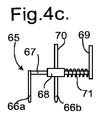
涙点を栓塞する代替的なより簡便な手法として、涙点又は隣接する涙小管をクリップによる外部圧力を加えることによって、閉止することができる。これは、2個の対向するジョー間に涙小管14又は15を挟み付けることによって行う。ジョーはねじ軸を使用して互いに接近し合うようにできるが、好適には、このようなジョーは弾性的に取付ける。挟み付け手法は、涙点12又は13自体に直接適用することができる。適当な遮閉具を図4c,4d及び4eに示す。各場合において、ジョーは代表的にはプラスチック材料とし、ばねはステンレス鋼のような金属とすることができる。
As an alternative and more convenient approach to plugging the punctum, the punctum or adjacent tubule can be closed by applying external pressure with a clip. This is done by sandwiching the
図4cに示すように、点状遮閉具65は互いに対向する1対のジョー66a及び66bを有し、一方のジョーはロッド67の端部に取付け、他方のジョーはスリーブ68から突出させ、ロッド67に沿って摺動できるようにする。ロッド67の反対側の端部には突出する指プレート69を固着し、また突出する第2指プレート70をスリーブ68から突出させ、圧縮ばね71がスリーブ68をロッド67に沿って押圧し、ジョー66a,66bが互いに接近するよう押圧する。オペレータが指プレート69及び70を互いにはさみ込み、ジョー66a,66bを互いに離間させ、ジョー66a及び66bを涙点12又は13の内側域で瞼の内側及び外側に配置させ、次に指プレート69及び70を釈放し、これによりジョー66a及び66bは対応の涙小管14又は15を挟み込んで閉鎖する。
As shown in FIG. 4 c, the
代案として、図4dに示すように、点状遮閉具73は、互いに回動可能に連結した2個のアーム75a及び75bの端部における互いに対向する1対のジョー74a及び74bを有し、アーム75a及び75bは、他方の端部で指プレート76a及び76bを画定し、また回動ピン77により結合し、指プレート76a及び76bを互いに引き離す方向に押圧する圧縮ばね78を配置する。この遮閉具73は、小型のばね負荷トング又ははさみに類似する。これは遮閉具65と同様にして使用し、すなわち、オペレータが指プレート76a及び76bを互いにはさみ込み、ジョー74a,74bを互いに離間させ、ジョー74a及び74bを涙点12又は13の内側域で瞼の内側及び外側に配置させ、次に指プレート76a及び76bを釈放し、これによりジョー74a及び74bは対応の涙小管14又は15を挟み込んで閉鎖する。
As an alternative, as shown in FIG. 4d, the point-shaped
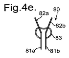
代案として、図4eに示すように、点状遮閉具80は互いに対向する1対のジョー81a及び81bを有し、これらジョー81a及び81bは、指プレート82a及び82bに一体にし、円筒体の一部としたばね83によって互いに保持する。この遮閉具80は小型のブルドッグクリップに類似する。これは上述した遮閉具65及び73と同様に使用する。
As an alternative, as shown in FIG. 4e, the point-
使用方法
灌流システム30は、シリンジ32に適当な液体、代表的には水又は生理食塩水を充填することによって準備する。次にシリンジ32をケーシング55に固着し、またケーシング55をプレート29に取付ける。チューブ38及び変換器モジュール40をシリンジ32に接続する。変換器モジュール40からのワイヤ56及び57をケーシング55にプラグ接続し、またカニューレ46を変換器モジュール40の端部に接続する。
Method of Use The
ケーシング55には、さらに、オン/オフのスイッチ及びプライミング/較正ボタン(図示せず)を設けることができる。この場合、スイッチをオン状態にし、システムの起動準備をし、またチェックする。このことにより、空気をシステムから追い出し、また圧力センサ42が予想通りに応答するのを確実にする。起動準備機能を動作させるとき、オペレータは、例えば、スイッチ48を2,3秒の間「オン」状態に押し続けることができる。このとき流体の流れが規定した流量又は流率で生じ、圧力センサ42の出力をモニタリングし、圧力は、先端部47が小さい直径であることに起因して上昇する。圧力が必要とされる限界内の値に達する場合、プライミング(起動準備動作)及び検査が満足のいくものであると見なされる。このことは、スピーカー52からの音声(又は色付きライト)によって表示される。このようにして記録される抵抗は、涙管を灌流しないときにおけるシステムの固有抵抗を表し、従って、この段階における抵抗レベルが自由な流れを表すものとしてシステムを較正することができる。
The
オペレータは、次に点状遮閉具を使用し、患者の眼10における一方の涙点、例えば、涙点12を塞ぐ。顕微鏡22により眼を観察しながら、オペレータは一方の手で患者の瞼を保持し、他方の手で変換器モジュール40を保持し、注意深くカニューレの先端部47を他方の涙点、この場合、下側涙点13に係合させる。オペレータは、スイッチ48の押下げを保持し、これによりリニアアクチュエータ34を上述したように動作させて、流体の流れを開始することができる。
The operator then uses a point shield to close one punctum in the patient's
適当な動作モードにおいて、マイクロプロセッサ50は、初期的には抵抗は正常値を有し、また液体の流れはプリセットした流量で開始するものと推測する。センサ42からの信号を使用して圧力をモニタリングし、また圧力が低過ぎる場合液体の流れが増大し、圧力が高過ぎる場合液体の流れは減少する。したがって、マイクロプロセッサ50は、圧力値のフィードバックを使用して、圧力を予め決定した範囲内の値にし、液体の流れを安定した状態にする。マイクロプロセッサ50における減衰回路は、幅広いゆれ又は行き過ぎを回避するよう構成し、迅速に安定状態に達するようにし、これにより必要な液体灌流量を少なくする。これによって、患者の検査をより快適にし、シリンジに液体を補充する必要性を少なくするのを確実にする。値が十分な時間にわたり、好適には少なくとも1秒、より好適には少なくとも2秒にわたり安定している場合、圧力又は流量の値を測定し、マイクロプロセッサは患者の涙管(涙点、この場合下側涙点13と鼻腔17との間)における抵抗を推定することができる。
In the appropriate mode of operation, the
流量(流速)は、代表的には5〜10ml/分の範囲内とし、注入圧力は、例えば、水柱10〜20cmの範囲内、すなわち1〜2kPaの範囲内とすることができる。健常者に関して、涙管抵抗は約6.7kPa・s/mlであるが、個人間では幅の広い変動があり、代表的には約4.4kPa・s/mlから9.0kPa・s/mlの変動があり得る。しかし、フィードバック制御システムにより、抵抗が正常よりも大幅に大きい、すなわち、排出系が完全に閉塞された個人において灌流システム30を安全にかつ正確に使用できるのを確実にする。
The flow rate (flow velocity) is typically in the range of 5 to 10 ml / min, and the injection pressure can be, for example, in the range of 10 to 20 cm of water column, that is, in the range of 1 to 2 kPa. For healthy individuals, lacrimal resistance is about 6.7 kPa · s / ml, but there are wide variations between individuals, typically from about 4.4 kPa · s / ml to 9.0 kPa · s / ml. There can be fluctuations. However, the feedback control system ensures that the
したがって、マイクロプロセッサ50が閾値を超える圧力を検出する場合、流れを減少し、流体の流れを完全に遮断し、患者に不快感を与えたり、涙管又はリニアアクチュエータ34に損傷を与えたりするのを回避する。
Thus, if the
上述したように、安定状態は適正持続時間で得られ、流量及び圧力の1つ又はそれ以上の測定値をマイクロプロセッサ50が記録する。この後、マイクロプロセッサ50は検査が成功したことを知らせる音声信号をスピーカー52から発生し、またリニアアクチュエータ34をスイッチオフする。次にマイクロプロセッサ50は抵抗結果(抵抗=圧力/流量)を計算し、また平均をとり、そしてディスプレイユニット51に結果を、随意的に健常者の対応グラフとの比較を伴って表示する。
As described above, a steady state is obtained with the proper duration, and the
使用の安全性は、変換器モジュール40内の圧力センサがプリセット限界又は閾値を超えて上昇する場合、先ずリニアアクチュエータ34の動作を止めることによって確保される。さらに、モータ過負荷検出器をリニアアクチュエータ34に設けることにより、可撓性チューブ38の閉塞を保護し、例えば変換器モジュール40内に高い圧力を生ずることなく流体流れの高い抵抗を生ずるような捻じれによる詰まりを保護する。
Safety of use is ensured by first deactivating the
灌流システム30は、外科医及び患者の双方にとって利点がある。外科医にとって、システム30は涙管抵抗に関する客観的なデータを提供し、又は測定は自然な生理学的状態に近い条件の下で行われる。測定は、顕微鏡を使用して、遮閉具挿入及びカニューレ46の先端部47の挿入、漏れチェックに関してよく見える状態で行うため、測定はより容易である。可撓性チューブ38のない手持ち灌流システム30を使用するとき、システムは軽量となり、人間工学的な手の位置が得られ、また手からカニューレ46の先端部47までの距離が比較的短くなるため、測定はさらに容易となる。患者を見通せることから、挿入中又は過剰圧力からの上昇中の何れかによる涙管損傷のリスクが少なくて測定はより安全であり、また液体の流量(流速)及び液量が少ないので、測定の不快感が少ない。
The
一方向弁44は、汚染物が可撓性チューブ38、又は可撓性チューブ38を設けない場合にシリンジ32に達するリスクを減少する。これにより変換器モジュール40及びカニューレ46は、一般的に使用後に使い捨て可能にするとともに、他のコンポーネントは汚染物転送リスクがなく再使用することができる。代案として、一方向弁44を設けない場合、シリンジ32、可撓性チューブ38、変換器モジュール40及びカニューレ46はすべて使い捨てにすることができる。
The one-
上述の灌流システム30は様々なやり方に変更することができる。例えば、カニューレ46は異なる形状のカニューレに代替することができる。
The
図5aにつき説明すると、代替的なカニューレ90は、一方の端部に変換器モジュール40の出口45に接続するためのハブ92を設け、他方の端部に狭小な短チューブ部分93に至る円滑な遷移部を設けた薄い壁厚のチューブ91を有する。これは上述したように短チューブ部分93を涙点12又は13内に挿入して使用する。
Referring to FIG. 5a, an
図5bに示すように、他の代替的なカニューレ94は、例えば0.64mmの均一な外径、及び例えば4又は5mmの長さを有するステンレス鋼製のチューブ95を有し、このチューブ95はカニューレ94の先端に向かって丸い表面をなすハブ96に挿入する。0.05mmの壁厚に対して内径は約0.54mmとすることができる。このサイズは、一般的に挿入手前で拡張する必要がなく、ハブ96が涙点12又は13に対する封止を行うことができる。代案として、チューブ95は、やはり0.05mmの壁厚で、外径0.57mmとすることができる。チューブ95は真っ直ぐなものとして示したが、長さに沿って僅かな湾曲を有することができる。
As shown in FIG. 5b, another
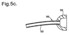
図5cにつき説明すると、これはカニューレ94の変更例であるカニューレ98を示し、この変更例は、僅かに湾曲したより長いチューブ99を有する点で異なっている。約9〜10mmの長さとし、これにより涙小管14又は15に沿って涙嚢16内まで通過することができ、ハブ96が涙点12又は13で封止する。このことは利点をもたらす。涙管の狭窄は、最も一般的には鼻涙管18で生ずることが知られており、涙管抵抗を測定するとき、実際に知りたいのは、この鼻涙管の部分における抵抗である。例えば、カニューレ94を使用して涙点12又は13から灌流する場合、このポイントの範囲外の全体抵抗を示すことになり、鼻涙管18の狭窄を識別するためには、涙小管14又は15が正常であると仮定しなければならない。カニューレ98は、鼻涙管18の流れ抵抗をより正確に測定することができ、例えば、カニューレ94を使用する測定と比べると、涙管の狭窄がどこで生じているかを示す客観的な測定値が得られる。
Referring to FIG. 5c, this shows a cannula 98, which is a variation of
変換器モジュール40は、さらに変更できる。例えば、液体の流れを阻止する機械的バルブを設け、このバルブは、ワイヤ57に電気信号を発生させる押しボタンスイッチ48を押すことにより操作するものとする。
The
Claims (15)
・カニューレ(46)に連通して液体を眼の涙点(12, 13)に供給し前記涙管を灌流させる、液体の流れを発生させる流れ発生手段であって、前記カニューレ(46)は、前記涙点(12, 13)を封止可能な先端部(47)を画定する、該流れ発生手段(32)と、
・前記流れ発生手段(32)を動作させるモータ(34)と、
・前記涙点(12, 13)に供給される液体の圧力をモニタリングする圧力センサ(42)と、
・前記圧力センサ(42)からの信号が供給されるモニタリング回路(50)であって、前記信号から前記流れ抵抗を表示するよう構成した、該モニタリング回路(50)と、
・前記圧力センサ(42)からの信号に従って前記モータ(34)を制御するフィードバック回路(50)であって、プリセットした液体圧力を維持する、又は前記液体圧力がプリセットした閾値を確実に超えないようにする、該フィードバック回路(50)と、
を備え、
前記流れ発生手段(32)は、流路を画定する1個又はそれ以上のコンポーネントを経て前記カニューレ(46)に連通し、
前記流路は、少なくとも部分的に短い管状剛性素子(40)によって画定され、前記短い管状剛性素子(40)に前記カニューレ(46)を取付け、
前記システム(30)は、オペレータが使用可能な位置でカニューレの近傍に設けた、灌流を制御可能にするスイッチ(48)を有し、
前記システム(30)は、
(a)携帯可能でバッテリ給電するものであり、手持ち操作可能に構成されている、または、
(b)前記流れ発生手段(32)及び前記モータ(34)が顕微鏡に取付け可能に構成されるとともに、前記流路が少なくとも部分的に可撓性チューブ(38)によって画定され、短い管状剛性素子(40)がオペレータによって指先で取扱い可能に構成されている、システム。 In the system (30) for confirming the flow resistance of the lacrimal duct by measuring the flow characteristics of the lacrimal duct (14, 15, 16, 18)
A flow generating means for generating a flow of fluid in communication with the cannula (46) to supply liquid to the punctum (12, 13) of the eye and perfuse the lacrimal duct, the cannula (46) The flow generating means (32) defining a tip (47) capable of sealing the punctum (12, 13);
A motor (34) for operating the flow generating means (32);
A pressure sensor (42) for monitoring the pressure of the liquid supplied to the punctum (12, 13);
A monitoring circuit (50) to which a signal from the pressure sensor (42) is supplied, the monitoring circuit (50) configured to display the flow resistance from the signal;
A feedback circuit (50) for controlling the motor (34) in accordance with a signal from the pressure sensor (42) to maintain a preset liquid pressure or to ensure that the liquid pressure does not exceed a preset threshold The feedback circuit (50),
With
The flow generating means (32) communicates with the cannula (46) via one or more components defining a flow path;
The flow path is at least partially defined by a short tubular rigid element (40), and the cannula (46) is attached to the short tubular rigid element (40);
The system (30) has a switch (48) provided in the vicinity of the cannula at a position where the operator can use it to control perfusion,
The system (30)
(A) Portable and battery-powered and configured to be handheld, or
(B) The flow generating means (32) and the motor (34) are configured to be attachable to a microscope, and the flow path is at least partially defined by a flexible tube (38), and a short tubular rigid element The system (40) is configured to be handled by a fingertip by an operator.
Applications Claiming Priority (3)
| Application Number | Priority Date | Filing Date | Title |
|---|---|---|---|
| GB1120771.9 | 2011-12-02 | ||
| GB201120771A GB201120771D0 (en) | 2011-12-02 | 2011-12-02 | tear duct resistance measuring system |
| PCT/GB2012/052964 WO2013079959A1 (en) | 2011-12-02 | 2012-11-30 | Tear duct resistance measuring system |
Publications (3)
| Publication Number | Publication Date |
|---|---|
| JP2015505685A JP2015505685A (en) | 2015-02-26 |
| JP2015505685A5 JP2015505685A5 (en) | 2015-12-10 |
| JP6062952B2 true JP6062952B2 (en) | 2017-01-18 |
Family
ID=45509076
Family Applications (1)
| Application Number | Title | Priority Date | Filing Date |
|---|---|---|---|
| JP2014543975A Active JP6062952B2 (en) | 2011-12-02 | 2012-11-30 | Lacrimal flow resistance measuring system and tubular element |
Country Status (7)
| Country | Link |
|---|---|
| US (2) | US9629540B2 (en) |
| EP (1) | EP2785239B1 (en) |
| JP (1) | JP6062952B2 (en) |
| CN (1) | CN104080395B (en) |
| ES (1) | ES2660780T3 (en) |
| GB (1) | GB201120771D0 (en) |
| WO (1) | WO2013079959A1 (en) |
Families Citing this family (8)
| Publication number | Priority date | Publication date | Assignee | Title |
|---|---|---|---|---|
| JP6249755B2 (en) * | 2013-12-13 | 2017-12-20 | 株式会社トプコン | Ophthalmic equipment |
| WO2016176252A1 (en) * | 2015-04-27 | 2016-11-03 | Khan Taj H | Biosensor canalicular stent |
| US20180193193A1 (en) * | 2015-07-06 | 2018-07-12 | The Regents Of The University Of Colorado, A Body Corporate | Lacrimal drainage system diagnostic implant |
| US20170333009A1 (en) * | 2016-05-19 | 2017-11-23 | Oregon Health & Science University | Instruments used in collecting fluid samples |
| CN107811629A (en) * | 2017-09-30 | 2018-03-20 | 温州医科大学附属眼视光医院 | A kind of lacrimal passage pressure detecting instrument of the pressure acquisition signal based on CS1237 chips, piezoresistance sensor and single-chip microcomputer |
| NL2020558B1 (en) * | 2018-03-09 | 2019-09-13 | D O R C Dutch Ophthalmic Res Center International B V | An ophthalmic pressure control system, a kit of parts and a method |
| JP7540431B2 (en) | 2019-03-26 | 2024-08-27 | ソニーグループ株式会社 | CONTROL DEVICE AND OPHTHALMIC MICROSCOPE SYSTEM |
| CN112451204A (en) * | 2019-09-09 | 2021-03-09 | 荷兰眼科研究中心(国际)有限公司 | Ophthalmic pressure control system, kit of parts and method |
Family Cites Families (16)
| Publication number | Priority date | Publication date | Assignee | Title |
|---|---|---|---|---|
| US4670006A (en) * | 1984-10-16 | 1987-06-02 | Sinnett Kevin B | Fluid and air infusion device |
| GB8610896D0 (en) * | 1986-05-03 | 1986-06-11 | Needle Industries Ltd | Ophthalmic aspirating/irrigating device |
| US5832930A (en) * | 1994-10-11 | 1998-11-10 | Bloom & Kreten | Clamp for nasolacrimal sac occlusion during administration of ocular medication |
| EP1225854A1 (en) * | 2000-08-29 | 2002-07-31 | Alcon Manufacturing Ltd. | Methods of controlling intraocular pressure and temperature |
| US20050048099A1 (en) * | 2003-01-09 | 2005-03-03 | Allergan, Inc. | Ocular implant made by a double extrusion process |
| US8016798B2 (en) * | 2003-02-24 | 2011-09-13 | Integrated Sensing Systems, Inc. | Fluid delivery system and sensing unit therefor |
| US7846126B2 (en) * | 2003-07-14 | 2010-12-07 | Abbott Medical Optics, Inc. | System and method for modulated surgical procedure irrigation and aspiration |
| US20050038323A1 (en) * | 2003-08-11 | 2005-02-17 | Knit Ventures, Llc | Tear duct endoscope for medication and sampling |
| JP5208916B2 (en) * | 2006-03-31 | 2013-06-12 | キュー エル ティー インク. | Drug delivery methods, structures and compositions for the nasolacrimal system |
| JP2010246573A (en) * | 2007-08-10 | 2010-11-04 | Saver Inc | Intraocular surgery instrument |
| WO2009111726A2 (en) | 2008-03-06 | 2009-09-11 | The Regents Of The University Of California | Measuring outlflow resistance/facility of an eye |
| US8162919B2 (en) * | 2008-12-08 | 2012-04-24 | Bausch & Lomb Incorporated | Flow control system based on leakage |
| US20100324476A1 (en) * | 2009-06-17 | 2010-12-23 | Mikhail Boukhny | Fluidics control via wireless telemetry |
| CA2770442C (en) * | 2009-08-19 | 2021-06-08 | Mirador Biomedical | Systems, methods, and devices for facilitating access to target anatomical sites or environments |
| US8147467B2 (en) * | 2009-09-24 | 2012-04-03 | Stephen C Chen | Noninvasive lacrimal canalicular occlusion device and method |
| US8460230B2 (en) * | 2010-09-16 | 2013-06-11 | The Cleveland Clinic Foundation | Lacrimal drainage manometer and method of use |
-
2011
- 2011-12-02 GB GB201120771A patent/GB201120771D0/en not_active Ceased
-
2012
- 2012-11-30 JP JP2014543975A patent/JP6062952B2/en active Active
- 2012-11-30 WO PCT/GB2012/052964 patent/WO2013079959A1/en active Application Filing
- 2012-11-30 ES ES12813416.0T patent/ES2660780T3/en active Active
- 2012-11-30 US US14/362,306 patent/US9629540B2/en active Active
- 2012-11-30 EP EP12813416.0A patent/EP2785239B1/en active Active
- 2012-11-30 CN CN201280068814.8A patent/CN104080395B/en active Active
-
2017
- 2017-03-27 US US15/470,517 patent/US20170196448A1/en not_active Abandoned
Also Published As
| Publication number | Publication date |
|---|---|
| ES2660780T3 (en) | 2018-03-26 |
| JP2015505685A (en) | 2015-02-26 |
| US9629540B2 (en) | 2017-04-25 |
| US20140358039A1 (en) | 2014-12-04 |
| CN104080395A (en) | 2014-10-01 |
| WO2013079959A1 (en) | 2013-06-06 |
| EP2785239B1 (en) | 2017-11-22 |
| EP2785239A1 (en) | 2014-10-08 |
| CN104080395B (en) | 2016-09-21 |
| GB201120771D0 (en) | 2012-01-11 |
| US20170196448A1 (en) | 2017-07-13 |
Similar Documents
| Publication | Publication Date | Title |
|---|---|---|
| JP6062952B2 (en) | Lacrimal flow resistance measuring system and tubular element | |
| US7648465B2 (en) | Method of testing a surgical system | |
| CN105813544B (en) | Pressure sensing vitrectomy surgery systems and method | |
| CA2931764C (en) | Devices, systems, and methods for aspiration bypass | |
| ES2432376T3 (en) | Procedure to test a surgical system | |
| US11253396B2 (en) | Liquid loss detection during laser eye surgery | |
| EP1062958B1 (en) | Software for controlling the operating parameters of a surgical system | |
| US20070249993A1 (en) | Method and device for irrigation of body cavities | |
| CA2822612A1 (en) | Ophthalmic surgical systems having intraocular pressure stabilizing apparatus | |
| JP6885950B2 (en) | Optical pressure measurement for ophthalmic surgical fluids | |
| EP2968798B1 (en) | Lacrimal drainage manometer | |
| JPS6266834A (en) | Ophthalmic instrument for measuring intraocular liquid pressure |
Legal Events
| Date | Code | Title | Description |
|---|---|---|---|
| A521 | Request for written amendment filed |
Free format text: JAPANESE INTERMEDIATE CODE: A523 Effective date: 20151020 |
|
| A621 | Written request for application examination |
Free format text: JAPANESE INTERMEDIATE CODE: A621 Effective date: 20151020 |
|
| A131 | Notification of reasons for refusal |
Free format text: JAPANESE INTERMEDIATE CODE: A131 Effective date: 20160712 |
|
| A977 | Report on retrieval |
Free format text: JAPANESE INTERMEDIATE CODE: A971007 Effective date: 20160713 |
|
| A521 | Request for written amendment filed |
Free format text: JAPANESE INTERMEDIATE CODE: A523 Effective date: 20160802 |
|
| TRDD | Decision of grant or rejection written | ||
| A01 | Written decision to grant a patent or to grant a registration (utility model) |
Free format text: JAPANESE INTERMEDIATE CODE: A01 Effective date: 20161213 |
|
| A61 | First payment of annual fees (during grant procedure) |
Free format text: JAPANESE INTERMEDIATE CODE: A61 Effective date: 20161215 |
|
| R150 | Certificate of patent or registration of utility model |
Ref document number: 6062952 Country of ref document: JP Free format text: JAPANESE INTERMEDIATE CODE: R150 |
|
| R250 | Receipt of annual fees |
Free format text: JAPANESE INTERMEDIATE CODE: R250 |
|
| R250 | Receipt of annual fees |
Free format text: JAPANESE INTERMEDIATE CODE: R250 |
|
| R250 | Receipt of annual fees |
Free format text: JAPANESE INTERMEDIATE CODE: R250 |
|
| R250 | Receipt of annual fees |
Free format text: JAPANESE INTERMEDIATE CODE: R250 |
|
| R250 | Receipt of annual fees |
Free format text: JAPANESE INTERMEDIATE CODE: R250 |