JP6061928B2 - Rotor refiner plate element for counter-rotating refiner with curved bar and serrated leading edge - Google Patents
Rotor refiner plate element for counter-rotating refiner with curved bar and serrated leading edge Download PDFInfo
- Publication number
- JP6061928B2 JP6061928B2 JP2014520363A JP2014520363A JP6061928B2 JP 6061928 B2 JP6061928 B2 JP 6061928B2 JP 2014520363 A JP2014520363 A JP 2014520363A JP 2014520363 A JP2014520363 A JP 2014520363A JP 6061928 B2 JP6061928 B2 JP 6061928B2
- Authority
- JP
- Japan
- Prior art keywords
- refining
- bar
- bars
- plate
- refiner
- Prior art date
- Legal status (The legal status is an assumption and is not a legal conclusion. Google has not performed a legal analysis and makes no representation as to the accuracy of the status listed.)
- Active
Links
- 238000007670 refining Methods 0.000 claims description 208
- 230000001788 irregular Effects 0.000 claims description 48
- 239000000758 substrate Substances 0.000 claims description 18
- 239000012978 lignocellulosic material Substances 0.000 claims description 8
- 230000008859 change Effects 0.000 claims description 3
- OOYGSFOGFJDDHP-KMCOLRRFSA-N kanamycin A sulfate Chemical group OS(O)(=O)=O.O[C@@H]1[C@@H](O)[C@H](O)[C@@H](CN)O[C@@H]1O[C@H]1[C@H](O)[C@@H](O[C@@H]2[C@@H]([C@@H](N)[C@H](O)[C@@H](CO)O2)O)[C@H](N)C[C@@H]1N OOYGSFOGFJDDHP-KMCOLRRFSA-N 0.000 claims 1
- 239000000835 fiber Substances 0.000 description 28
- 239000002023 wood Substances 0.000 description 22
- 239000000463 material Substances 0.000 description 18
- 230000014759 maintenance of location Effects 0.000 description 15
- 230000006835 compression Effects 0.000 description 13
- 238000007906 compression Methods 0.000 description 13
- 238000013461 design Methods 0.000 description 8
- 238000000034 method Methods 0.000 description 8
- 230000008569 process Effects 0.000 description 7
- 238000004537 pulping Methods 0.000 description 6
- 229920001131 Pulp (paper) Polymers 0.000 description 3
- 239000002245 particle Substances 0.000 description 3
- 239000002994 raw material Substances 0.000 description 3
- 238000005520 cutting process Methods 0.000 description 2
- 230000003247 decreasing effect Effects 0.000 description 2
- 238000004519 manufacturing process Methods 0.000 description 2
- 238000010008 shearing Methods 0.000 description 2
- 230000007704 transition Effects 0.000 description 2
- XLYOFNOQVPJJNP-UHFFFAOYSA-N water Chemical compound O XLYOFNOQVPJJNP-UHFFFAOYSA-N 0.000 description 2
- 229920002522 Wood fibre Polymers 0.000 description 1
- 230000009471 action Effects 0.000 description 1
- 238000013459 approach Methods 0.000 description 1
- 230000008901 benefit Effects 0.000 description 1
- 206010061592 cardiac fibrillation Diseases 0.000 description 1
- 239000012141 concentrate Substances 0.000 description 1
- 238000007796 conventional method Methods 0.000 description 1
- 238000005265 energy consumption Methods 0.000 description 1
- 230000002600 fibrillogenic effect Effects 0.000 description 1
- 239000002657 fibrous material Substances 0.000 description 1
- 238000012986 modification Methods 0.000 description 1
- 230000004048 modification Effects 0.000 description 1
- 238000000465 moulding Methods 0.000 description 1
- 230000007935 neutral effect Effects 0.000 description 1
- 230000000737 periodic effect Effects 0.000 description 1
- 230000009467 reduction Effects 0.000 description 1
- 230000003252 repetitive effect Effects 0.000 description 1
- 230000000717 retained effect Effects 0.000 description 1
- 230000000630 rising effect Effects 0.000 description 1
- 238000000926 separation method Methods 0.000 description 1
- 238000007493 shaping process Methods 0.000 description 1
- 239000002025 wood fiber Substances 0.000 description 1
Images


Classifications
-
- D—TEXTILES; PAPER
- D21—PAPER-MAKING; PRODUCTION OF CELLULOSE
- D21D—TREATMENT OF THE MATERIALS BEFORE PASSING TO THE PAPER-MAKING MACHINE
- D21D1/00—Methods of beating or refining; Beaters of the Hollander type
- D21D1/20—Methods of refining
- D21D1/30—Disc mills
- D21D1/306—Discs
-
- D—TEXTILES; PAPER
- D21—PAPER-MAKING; PRODUCTION OF CELLULOSE
- D21D—TREATMENT OF THE MATERIALS BEFORE PASSING TO THE PAPER-MAKING MACHINE
- D21D1/00—Methods of beating or refining; Beaters of the Hollander type
- D21D1/20—Methods of refining
- D21D1/30—Disc mills
- D21D1/303—Double disc mills
-
- D—TEXTILES; PAPER
- D21—PAPER-MAKING; PRODUCTION OF CELLULOSE
- D21D—TREATMENT OF THE MATERIALS BEFORE PASSING TO THE PAPER-MAKING MACHINE
- D21D1/00—Methods of beating or refining; Beaters of the Hollander type
- D21D1/20—Methods of refining
- D21D1/30—Disc mills
Landscapes
- Paper (AREA)
Description
本出願は、2012年7月12日に出願された特許出願第13/547,144号及び2011年7月13日に出願された特許出願第61/507,450号の利益を主張するものであり、これらの全てが参照として本願に包含されている。 This application claims the benefit of Patent Application No. 13 / 547,144 filed on July 12, 2012 and Patent Application No. 61 / 507,450 filed on July 13, 2011. All of which are hereby incorporated by reference.
本発明はリグノセルロース系材料のためのディスクリファイナー、例えばメカニカルパルプ、サーモメカニカルパルプ及び種々のケミサーモメカニカルパルプを製造するために使用されるディスクリファイナーに関する(これらのパルプをメカニカルパルプ、これらのパルプ化プロセスをメカニカルパルプ化プロセスとそれぞれ総称する)。 The present invention relates to disc refiners for lignocellulosic materials, for example mechanical pulps, thermomechanical pulps and disc refiners used to produce various chemithermomechanical pulps (these pulps are mechanical pulps, their pulping). Processes are collectively referred to as mechanical pulping processes).
メカニカルパルプ化プロセスで使用される逆回転リファイナーにおいて、原材料、典型的には、木材又は他のリグノセルロース系材料(木材チップと総称される)が、リファイナーディスクの1つの中央を通って供給され、1つ又は両方のローターディスクの回転によって作り出された強い遠心力によって外側方向に推進される。リファイナープレートはリファイナーディスクの対向面のそれぞれに装着される。木材チップは対向リファイナープレートの間を一般に半径方向にプレート及びディスクの外縁へと移動する。 In a counter-rotating refiner used in a mechanical pulping process, raw materials, typically wood or other lignocellulosic materials (collectively referred to as wood chips) are fed through the center of one of the refiner discs, Driven outward by the strong centrifugal force created by the rotation of one or both rotor disks. A refiner plate is mounted on each of the opposing surfaces of the refiner disk. The wood chips move between the opposing refiner plates, generally radially, to the outer edges of the plates and disks.
リファイナーディスクは、1分間あたり1200〜1800回転(RPM)の回転スピードで従来稼働している。木材チップがディスクの間にある間に、エネルギーがディスクに取り付けられたリファイナープレートを介して材料に伝達される。リファイナープレートはバーと溝とのパターン及びダムを一般に特徴とし、これらが一緒になって、リグノセルロース系繊維材料に繰り返しの圧縮及び剪断作用を提供する。材料に対する圧縮及び剪断作用は、リグノセルロース系繊維を原材料から分離し、材料のある程度の解繊又はフィブリル化を提供し、通常あまり望ましくない幾らかの繊維の切断を生じる。繊維の分離及び解繊は、原木チップを適当な板材又は製紙用繊維成分に変換するために必要である。 Refiner disks are conventionally operating at a rotational speed of 1200-1800 revolutions per minute (RPM). While the wood chips are between the disks, energy is transferred to the material via a refiner plate attached to the disks. Refiner plates generally feature bar and groove patterns and dams, which together provide repeated compression and shearing to the lignocellulosic fiber material. The compressive and shearing action on the material separates the lignocellulosic fibers from the raw material and provides some degree of defibration or fibrillation of the material, usually resulting in some undesirable fiber cutting. Separation and defibration of the fibers are necessary to convert the raw wood chips into a suitable board or paper fiber component.
メカニカルパルプ化プロセスでは、例えば木材チップとリファイナープレートとの間で大量の摩擦が起こり、この摩擦はプロセスのエネルギー効率を減少させる。メカニカルパルプ化で適用されるエネルギーの効率は、10パーセント(%)〜15%のオーダーであると推計されている。 In the mechanical pulping process, for example, a large amount of friction occurs between the wood chips and the refiner plate, and this friction reduces the energy efficiency of the process. The efficiency of energy applied in mechanical pulping has been estimated to be on the order of 10 percent (%) to 15%.
より高いエネルギー効率、例えばより低い摩擦で稼働するリファイナープレートを開発するための取り組みがなされ、この取り組みはディスク間の稼働ギャップを減少させることに典型的に関係している。エネルギー効率を改善するための従来の技術は、リファイナープレート上のリファイニングゾーンを横切る木材チップの供給を通常スピードアップさせるリファイナープレートセグメントの前面上のデザイン特徴に典型的に関係している。これらの技術はリファイナープレート間を流れる木材チップによって形成された繊維パッドの厚さを減少させる結果となることがしばしばである。エネルギーがリファイナープレートによって、より薄い繊維パッドに適用されるとき、木材チップに適用される圧縮率は、与えられたエネルギー投入量に対してより大きくなり、木材チップのリファイニングにおいてより効率的なエネルギー使用となる。 Efforts have been made to develop refiner plates that operate with higher energy efficiency, eg, lower friction, and this approach is typically associated with reducing the operating gap between the disks. Conventional techniques for improving energy efficiency typically relate to design features on the front of refiner plate segments that typically speed up the supply of wood chips across the refining zone on the refiner plate. These techniques often result in a reduction in the thickness of the fiber pad formed by the wood chips flowing between the refiner plates. When energy is applied to the thinner fiber pad by the refiner plate, the compressibility applied to the wood chips is greater for a given energy input and more efficient energy in refining wood chips. Will be used.
繊維パッドの厚さを減少させることは、例えば対向リファイナープレート間の間隔などの稼働ギャップをより小さくすることを可能とする。ギャップを減少させることは、木材チップの繊維の切断の増大、ディスクによって製造されたパルプの強度特性の減少、リファイナープレートの摩耗率の増大、及びリファイナープレートの稼働寿命の減少をもたらす。 Reducing the thickness of the fiber pad allows for a smaller operating gap, such as the spacing between opposing refiner plates. Decreasing the gap results in increased fiber cutting of the wood chip, reduced strength properties of the pulp produced by the disk, increased wear rate of the refiner plate, and decreased service life of the refiner plate.
エネルギー効率はリファイナーディスクの外縁に向かって最大になると考えられている。リファイナープレートの相対的な速度はプレートの外縁領域において最大である。リファイナープレート上のリファイニングバーは、リファイナープレートの外縁領域における対向プレート上でより高い速度で互いに交差する。リファイニングバーのより高い交差速度は、プレートの外縁領域におけるリファイニング効率を増大させると考えられている。 Energy efficiency is believed to be maximized towards the outer edge of the refiner disk. The relative speed of the refiner plate is maximum in the outer edge region of the plate. The refining bars on the refiner plate intersect each other at a higher speed on the opposing plate in the outer edge region of the refiner plate. The higher crossing speed of the refining bar is believed to increase the refining efficiency in the outer edge region of the plate.
木材繊維はリファイナープレートの外縁領域を迅速に流れる傾向がある。外縁領域における繊維の迅速性は、強い遠心力、及びディスク間に生じた水蒸気の前方への流れによって作り出される力による。外縁領域における保持時間の短さは、リファイニング表面の最も効率的な部分で行われる仕事の量を制限する。 Wood fibers tend to flow quickly through the outer edge area of the refiner plate. The rapidity of the fibers in the outer edge region is due to the strong centrifugal force and the force created by the forward flow of water vapor generated between the disks. The short holding time in the outer edge region limits the amount of work done on the most efficient part of the refining surface.
エネルギー投入のより多くをリファイニングゾーンの外縁に向かってシフトさせるようにリファイナープレートをデザインすることは、全体のリファイニング効率を増大させ、パルプをリファインするために消費されるエネルギーを減少させる。エネルギー投入をリファイニングゾーンの外縁にシフトさせ、リファイナープレート間の稼働ギャップをより大きくすることは、リファイナープレートの長い稼働寿命を提供するのに十分であるはずである。 Designing the refiner plate to shift more of the energy input towards the outer edge of the refining zone increases the overall refining efficiency and reduces the energy consumed to refine the pulp. Shifting the energy input to the outer edge of the refining zone and increasing the working gap between the refiner plates should be sufficient to provide a long working life for the refiner plates.
新規なリファイナープレートが発明され、このリファイナープレートは、1つの実施形態において、向上したエネルギー効率を有し、ディスク間の比較的大きな稼働ギャップを可能とする。向上したエネルギー効率及び大きな稼働ギャップによって、パルプを製造するためのエネルギー消費の減少、製造されたパルプの高い繊維品質及びリファイナープレートセグメントの長い稼働寿命を提供する。 A new refiner plate has been invented, which in one embodiment has improved energy efficiency and allows for a relatively large working gap between the disks. Improved energy efficiency and large operating gap provide reduced energy consumption to produce pulp, high fiber quality of the pulp produced and long service life of the refiner plate segment.
1つの実施形態において、リファイナープレートはロータープレートセグメントのアセンブリであり、ロータープレートセグメントはバーを備える外側リファイニングゾーンを有し、バーは湾曲した縦形状と、リーディング壁面を備える半径方向外側区分とを少なくとも有し、壁面はギザギザ、鋸歯又は他の不規則なものである。湾曲したバー及びその結果としてのバーの間の湾曲した溝は、外側ゾーンにおける木材チップ供給材料の保持時間を増大させ、それによって外側ゾーンによる材料のリファイニングを増大させる。さらにリーディング側壁上のギザギザの表面も、外側ゾーンにおける供給材料の保持時間を増大させるように作用する。 In one embodiment, the refiner plate is an assembly of rotor plate segments, the rotor plate segment having an outer refining zone comprising a bar, the bar having a curved longitudinal shape and a radially outer section comprising a leading wall. At least the walls are jagged, sawtooth or other irregular. The curved groove between the curved bar and the resulting bar increases the retention time of the wood chip feed material in the outer zone, thereby increasing the refining of the material by the outer zone. In addition, the jagged surface on the leading sidewall also acts to increase the retention time of the feed in the outer zone.
リファイニングプレートが発明され、このリファイニングプレートはもう1つのプレートと対面するリファイニング表面を備え、リファイニング表面は表面から立ち上がる複数のバーを含み、バーはプレートの外縁エッジに向かって外方向に延び、バーはギザギザ又は不規則な表面をバーの少なくともリーディング側壁上に有し、バーは湾曲し、例えば指数関数状であるか又はインボリュート弧(involute arc)状である。リファイニングプレートはロータープレートであり、もう1つのロータープレートと反対のリファイナーに配置される。 A refining plate was invented, the refining plate comprising a refining surface facing another plate, the refining surface comprising a plurality of bars rising from the surface, the bars extending outwardly towards the outer edge of the plate Elongated, the bar has a jagged or irregular surface on at least the leading side wall of the bar, the bar being curved, for example exponential or involute arc-shaped. The refining plate is a rotor plate and is placed on the refiner opposite the other rotor plate.
リグノセルロース系材料のメカニカルリファイナーのためのリファイニングプレートセグメントが発明され、このセグメントは、
基板上にリファイニング表面を含み、
このリファイニング表面は対向するリファイナープレートのリファイニング表面に対面するように適合され、
このリファイニング表面はバー、及びバー同士の間の溝を含み、
バーに対応する半径ラインに対して、それぞれのバーの角度は半径方向外側の方向に沿って少なくとも10〜15度増大し、
この角度はリファイニング表面の外縁において10〜45度、15〜35度、15〜45度及び20〜35度の範囲のいずれかのホールドバック角(holdback angle)であり、
バーは、不規則な表面を有するリーディング側壁をそれぞれ含み、
この不規則な表面は、側壁から隣接するバー上の側壁に向かって外方向に延びる突起を含み、
この不規則な表面はリファイニング表面の外縁又はその付近から延び、リファイニング表面の入口に達することなくバーに沿って半径方向内側に延びている。
A refining plate segment for a mechanical refiner of lignocellulosic material was invented and this segment was
Including a refining surface on the substrate,
This refining surface is adapted to face the refining surface of the opposing refiner plate,
The refining surface includes bars and grooves between the bars,
For each radial line corresponding to a bar, the angle of each bar increases by at least 10-15 degrees along the radially outward direction,
This angle is any holdback angle in the range of 10-45 degrees, 15-35 degrees, 15-45 degrees and 20-35 degrees at the outer edge of the refining surface;
The bars each include a leading side wall with an irregular surface;
This irregular surface includes protrusions extending outwardly from the sidewalls toward the sidewalls on the adjacent bar;
This irregular surface extends from or near the outer edge of the refining surface and extends radially inward along the bar without reaching the inlet of the refining surface.
バーは、バーが延びるプレートの半径に対して湾曲した縦形状をそれぞれ有する。その角度は半径方向外側の方向に沿って連続的且つ徐々に増大するか、又は半径方向外側の方向に沿って段階的に増大する。リファイニング表面への半径方向内側の入口において、バーは、バーに対応する半径ラインの10度、15度又は20度以内の角度でそれぞれ配置される。さらに、リファイナープレートセグメントは回転リファイニングディスクのために適合され、リファイナーに装着されたとき、回転リファイニングディスクに対面するように適合されている。 Each bar has a longitudinal shape that is curved with respect to the radius of the plate from which the bar extends. The angle increases continuously and gradually along the radially outward direction or stepwise along the radially outward direction. At the radially inner entrance to the refining surface, the bars are each arranged at an angle within 10 degrees, 15 degrees or 20 degrees of the radial line corresponding to the bars. Furthermore, the refiner plate segment is adapted for a rotating refining disc and is adapted to face the rotating refining disc when mounted on the refiner.
リファイニング表面は複数のリファイニングゾーンを含むことがあり、第1リファイニングゾーンは比較的広いバー及び広い溝を有し、第2リファイニングゾーンは比較的狭いバー及び狭い溝を有し、第2リファイニングゾーンは、第1リファイニングゾーンからプレートセグメント上で半径方向外側にあり、第2リファイニングゾーンのホールドバック角は10〜45度、15〜45度及び20〜35度の範囲のいずれかである。 The refining surface may include a plurality of refining zones, the first refining zone having relatively wide bars and wide grooves, the second refining zone having relatively narrow bars and narrow grooves, The two refining zones are radially outward on the plate segment from the first refining zone, and the holdback angle of the second refining zone is any of 10-45 degrees, 15-45 degrees and 20-35 degrees It is.
バーのリーディング側壁上の不規則な表面は一連の斜面を含むことがあり、この斜面はそれぞれの溝の基板において下部エッジをそれぞれ有し、リーディング側壁を少なくとも部分的に上に延びている。 The irregular surface on the leading sidewall of the bar may include a series of bevels, each having a lower edge in the substrate of each groove, extending at least partially above the leading sidewall.
リグノセルロース系材料のメカニカルリファイナーのためのリファイナープレートが発明され、このプレートは、
基板上のリファイニング表面を含み、
このリファイニング表面は対向するリファイナープレートのリファイニング表面に対面するように適合され、
このリファイニング表面はバー、及びバー同士の間の溝を含み、
バーは、バーの入口において半径ラインの10、15又は20度以内である対応半径ラインに対するそれぞれのバーの角度と、バーの外縁において10〜45、15〜35、15〜45及び20〜35度の範囲にあるホールドバック角とを有する半径方向外側区分を少なくとも有し、
この角度は、バーの半径方向内側の入口から外縁まで少なくとも10〜15度増大し、
バーは、半径方向外側区分において不規則な表面を有する側壁をそれぞれ含み、
この不規則な表面は、側壁から隣接するバー上の側壁に向かって外側に延びる突起を含み、
このバーは、不規則な表面を有するリーディング側壁をそれぞれ含み、
この不規則な表面は、側壁から隣接するバー上の側壁に向かって外側に延びる突起を含み、
この不規則な表面は、リファイニング表面の外縁又はその近傍から延び、リファイニング表面の入口に達することなく、バーに沿って半径方向内側に延びている。
A refiner plate for a mechanical refiner of lignocellulosic material was invented,
Including a refining surface on the substrate,
This refining surface is adapted to face the refining surface of the opposing refiner plate,
The refining surface includes bars and grooves between the bars,
The bars are angled to the corresponding radial line that is within 10, 15 or 20 degrees of the radial line at the bar entrance and 10-45, 15-35, 15-45 and 20-35 degrees at the outer edge of the bar. At least a radially outer section having a holdback angle in the range of
This angle increases at least 10-15 degrees from the radially inner entrance to the outer edge of the bar,
The bars each include sidewalls having irregular surfaces in the radially outer section;
This irregular surface includes protrusions extending outwardly from the sidewalls toward the sidewalls on the adjacent bar;
The bars each include a leading side wall with an irregular surface,
This irregular surface includes protrusions extending outwardly from the sidewalls toward the sidewalls on the adjacent bar;
This irregular surface extends from or near the outer edge of the refining surface and extends radially inward along the bar without reaching the inlet of the refining surface.
リグノセルロース系材料のメカニカルリファイナーのためのリファイニングプレートセグメントが発明され、このセグメントは、
基板上のリファイニング表面を含み、
このリファイニング表面は対向するリファイナープレートのリファイニング表面に対面するように適合され、
このリファイニング表面はバー及びバー同士の間の溝を含み、
それぞれのバーは、バーに対応する半径ラインに対してある角度にあり、
バーへの入口におけるその角度は半径ラインの少なくとも10、15又は20度であり、この角度はバーに沿って半径方向外側の方向に少なくとも10〜15度増大し、この角度はリファイニング表面の外縁において10〜45、15〜45、15〜35又は20〜35度の範囲にあり、
このバーは、不規則な表面を有するリーディング側壁をそれぞれ含み、
この不規則な表面は、側壁から隣接するバー上の側壁に向かって外側に延びる突起を含み、
この不規則な表面は、リファイニング表面の外縁又はその近傍から延び、リファイニング表面の入口に達することなく、バーに沿って半径方向内側に延びている。
A refining plate segment for a mechanical refiner of lignocellulosic material was invented and this segment was
Including a refining surface on the substrate,
This refining surface is adapted to face the refining surface of the opposing refiner plate,
The refining surface includes bars and grooves between the bars,
Each bar is at an angle with respect to the radial line corresponding to the bar,
Its angle at the entrance to the bar is at least 10, 15 or 20 degrees of the radial line, this angle increasing at least 10-15 degrees radially outward along the bar, this angle being the outer edge of the refining surface In the range of 10-45, 15-45, 15-35 or 20-35 degrees,
The bars each include a leading side wall with an irregular surface,
This irregular surface includes protrusions extending outwardly from the sidewalls toward the sidewalls on the adjacent bar;
This irregular surface extends from or near the outer edge of the refining surface and extends radially inward along the bar without reaching the inlet of the refining surface.
図1は、第1プレートセグメントの側面図である。 FIG. 1 is a side view of the first plate segment.
図2は、第1リファナープレートセグメントの正面図である。 FIG. 2 is a front view of the first referrer plate segment.
図3及び図4は、第2リファイナープレートセグメントのそれぞれ側
面図及び正面図である。
3 and 4 are a side view and a front view, respectively, of the second refiner plate segment.
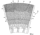
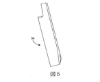
図5及び図6は、第3リファイナープレートセグメントのそれぞれ側面図及び正面図である。 5 and 6 are a side view and a front view, respectively, of the third refiner plate segment.
図7は、リファイナープレートセグメント上のバーのギザギザの側壁の一例の拡大図である。 FIG. 7 is an enlarged view of an example of a knurled sidewall of a bar on a refiner plate segment.
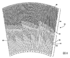
図8は、もう1つのリファイナープレートセグメントの正面図である。 FIG. 8 is a front view of another refiner plate segment.
図9〜図12は、リファイナープレートセグメント上の外側リファイニングゾーンにおけるバーのリーディング側壁上の不規則な表面の一例の上から下への図をそれぞれ示す。 FIGS. 9-12 show top-to-bottom views of examples of irregular surfaces on the leading sidewall of the bar in the outer refining zone on the refiner plate segment, respectively.
図13は、バーのリーディング側壁上の不規則な表面を有するリファイニングバーの断面概略図である。 FIG. 13 is a cross-sectional schematic view of a refining bar having an irregular surface on the leading side wall of the bar.
図14は、図13に示されるバーのリーディング側壁の正面図である。 14 is a front view of the leading side wall of the bar shown in FIG.
リファイニングプロセスは、周期的な圧縮を、メカニカルリファイナーのディスク間の稼働ギャップ中を移動している木材チップからなる繊維パッドに適用する。リファイニングプロセスのエネルギー効率は、繊維パッドの圧縮率を増大させ、例えばリファイニングゾーンの半径方向内側部分などにおいて、より低い圧縮率で適用されるリファイニングエネルギーのパーセンテージを減少させることによって改善される。増大した圧縮率は、本明細書に開示されたロータープレートのデザインで達成され、従来のより高いエネルギー効率のリファイナープレートで行われているのと同程度に稼働ギャップを減少させることは必ずしも必要ではない。 The refining process applies periodic compression to a fiber pad consisting of wood chips moving through a working gap between the disks of a mechanical refiner. The energy efficiency of the refining process is improved by increasing the compressibility of the fiber pad, for example by reducing the percentage of refining energy applied at a lower compressibility, such as in the radially inner portion of the refining zone. . The increased compression ratio is achieved with the rotor plate design disclosed herein, and it is not necessary to reduce the operating gap as much as is done with conventional higher energy efficiency refiner plates. Absent.
リファイナーにおけるロータープレートとステータープレートとの間の稼働ギャップが(高エネルギー効率リファイナーにおける狭いギャップと比較して)相対的に広いと、プレート間に形成されるパルプパッドはより厚くなる。高圧縮率は、類似の高エネルギー効率用途で使用される従来のロータープレートと比較して、有意により粗いリファイナープレートを使用して厚いパルプパッドで達成される。 If the working gap between the rotor plate and the stator plate in the refiner is relatively wide (compared to the narrow gap in the high energy efficiency refiner), the pulp pad formed between the plates will be thicker. High compressibility is achieved with thicker pulp pads using significantly coarser refiner plates compared to conventional rotor plates used in similar high energy efficiency applications.
粗いリファイナープレートは、高エネルギー効率リファイナーで典型的に使用される細かいリファイナープレートと比較して、相対的に少ないバーを有する。粗いリファイナープレートにおけるより少ないバーの数は、ローター上のバーがステーター上のバーを横切って通過するときに適用される圧縮周期を減少させる。より少ない圧縮周期で伝達されるエネルギーは、圧縮機会及び剪断機会のそれぞれの強度を増大させ、エネルギー効率を増大させる。 A coarse refiner plate has relatively few bars compared to a fine refiner plate typically used in high energy efficiency refiners. The smaller number of bars in the coarse refiner plate reduces the compression period applied when the bars on the rotor pass across the bars on the stator. Energy transmitted with fewer compression cycles increases the strength of each compression and shear opportunity and increases energy efficiency.
本明細書に開示されたローターリファイナープレートのデザインは、繊維の長さを維持し、リファイナープレートの耐用寿命を改善しながら、高い繊維保持及び高い圧縮を達成し、高エネルギー効率を提供する。これらのデザインは、類似のデザインが両方のローターディスク上で稼働する逆回転のリファイナーで使用される。 The rotor refiner plate design disclosed herein achieves high fiber retention and compression and provides high energy efficiency while maintaining fiber length and improving refiner plate life. These designs are used in counter-rotating refiners where similar designs run on both rotor disks.
リファイナープレートが発明され、このリファイナープレートは比較的粗いバーと溝との構成、及びリファイニングゾーンの外縁領域にある有効リファイニングゾーンにおいて繊維パッドに対する長い保持時間を提供するための他の特徴を備えている。これらの特徴は、バーの交差の回数がより少ないこと(圧縮機会がより少ないこと)及び原材料に対する保持時間がはるかにより長いことと共に、リファイニング表面の外縁に向かう表面エリアによってリファイニングエネルギーを集中させるが、これらはローターエレメント又はローターリファイナープレートの特異なデザインによってもたらされる。これにより厚い繊維マットは高圧縮率となり、従ってより大きい稼働ギャップを維持するようになる。対向するプレート間の繊維の量を減少させることによって高強度を達成する代わりに、バーの交差機会の回数を少なくし、交差するそれぞれのバーに存在する繊維の量を増大させることによっても高強度圧縮が達成される。 A refiner plate has been invented, which comprises a relatively coarse bar and groove configuration and other features to provide a long retention time for the fiber pad in the effective refining zone in the outer edge region of the refining zone. ing. These features concentrate the refining energy by the surface area towards the outer edge of the refining surface, along with fewer bar crossings (less compression opportunities) and a much longer retention time for the raw material However, these are brought about by the unique design of the rotor element or rotor refiner plate. This allows the thick fiber mat to have a high compression ratio and thus maintain a larger working gap. Instead of achieving high strength by reducing the amount of fibers between opposing plates, high strength is also achieved by reducing the number of bar crossing opportunities and increasing the amount of fiber present in each crossing bar. Compression is achieved.
本明細書に開示するリファイナープレートは、リファイニングゾーンの外縁領域において少なくともギザギザのリーディング側壁を備える湾曲したバーを有する。バーの湾曲及びギザギザのリーディング側壁は、繊維マッドを減速させ、それによってリファイニングゾーンの外縁領域におけるパルプの保持を増大させる。保持時間が増大することで、パルプへのエネルギー投入がより効率的であるリファイナーの外縁に向かってより大きなエネルギー投入が可能になる。 The refiner plate disclosed herein has a curved bar with at least jagged leading sidewalls in the outer edge region of the refining zone. The curvature of the bar and the jagged leading sidewall slow down the fiber mud, thereby increasing pulp retention in the outer edge region of the refining zone. Increasing the retention time allows greater energy input towards the outer edge of the refiner where energy input to the pulp is more efficient.
図1及び図2は、入口区分12及び外側区分14を有するロータープレートセグメント10の側面図及び正面図をそれぞれ示す。一連のプレートセグメントは、円環のリファイニングプレートを形成するために環状に配置される。プレートセグメント10はプレートとしてディスク11に装着される。ディスクリファイナーにおいて、ロータープレートは、プレート間のリファイニングギャップを有しながらもう1つのロータープレートと対面する。反対側のロータープレートも、第1ロータープレートセグメントと類似のバー及び溝の特徴を有するか又は他のバー及び溝の特徴を有するプレートセグメントで形成される。ロータープレートの回転方向(矢印16)は反時計回りである。
1 and 2 show a side view and a front view, respectively, of a
リファイナープレートセグメントの外側区分14は、エネルギーが木材チップ供給材料をリファインするために適用されるエリアである。外側区分は100ミリメートル(mm)〜200mmの間の半径距離であることが好ましい。外側区分は、バーに対応する半径ラインに対して段階的又は徐々に増大する角度を形成する湾曲したバー18を含む。それぞれのバー18の内側端において、バーと半径ラインとの間の角度19は、0度又は数度以内であり、例えば10度,15度又は20度以内である。バーの入口角度18の方向は供給方向又はホールドバック方向である。
The
供給角及びホールドバック角は、バー18がプレートの相対的な動きに対して形成する角度である。供給角度は半径ラインの反対方向から、ロータープレートとしての回転、例えば矢印16で示される反時計回りへの角度である。ホールドバック角はバーに対応する半径ラインからの角度であり、ロータープレートの回転方向に延びている。供給角はバーに対応する半径ラインからの角度であり、プレートの回転に反対方向に延びている。
The supply angle and holdback angle are the angles that the
バーの半径方向外側端において、バー出口角度20は、10〜45度、15〜35度、15〜45度又は20〜35度の範囲のホールドバック角である。ホールドバック角は、異なる角度を有する一連の直線バー区分としてそれぞれのバーを形成することによりバー角度に段階的な変化を提供することによって増大されることもある。
At the radially outer end of the bar, the
溝22はバー同士の間にあり、隣接するバーのトレイリング側壁24及びリーディング側壁26によって規定される。リーディング側壁は対向するロータープレートの回転方向に対面する。図2において、リーディング側壁はそれぞれのバーの左手側(L)上にある。溝は、供給材料、水蒸気及び他の材料がプレートを通って半径方向に移動できる通路を提供する。
The groove 22 is between the bars and is defined by the trailing
バーの高さ、例えばプレートの基板前表面からバーの上部リッジまでの距離は、最初はテーパー状であるが、バーの長さのほとんどに渡って均一な高さになるように遷移する。バーの最初のテーパー部は、外側区分14への材料の供給を促進する。
The height of the bar, for example the distance from the front substrate surface of the plate to the upper ridge of the bar, is initially tapered but transitions to a uniform height over most of the length of the bar. The first taper of the bar facilitates the supply of material to the
プレートセグメント10において、入口角度はニュートラルであり、例えば半径ラインに対して約0度である。プレートセグメントの外縁30において、バー18の出口角度20は、10〜60度、10〜45度、20〜30度及び15〜35度の範囲の1つのホールドバック角である。
In the
バー18の角度は、ロータープレートの回転に一致する角度方向に入り口から出口まで徐々に増大する。ロータープレートセグメント10において、その角度は入口付近ではゆっくりと増大する。角度の変化率は、バーがプレートの外縁30に向かって移行すると徐々に増大する。入口からリファイニングゾーンの外縁までの角度の増分は、最小で10〜15度の増分である。バーの角度は指数関数状の弧又はインボリュート弧状に増大する。
The angle of the
リファイニングゾーンの外側部分、例えば外側区分14におけるバーの高ホールドバック角20は、プレート間の供給材料の高保持、及び外側区分14によって示されるリファイニングゾーンの外側部分における供給材料の増大した保持時間に寄与する。
The
例えば10〜45度の高ホールドバック角やバーのリーディング側壁上のギザギザの表面は、リファイニングゾーンの外側領域に限られる。外側領域はリファイニングゾーンの外側の80%から20%である。 For example, a high holdback angle of 10 to 45 degrees or a jagged surface on the leading side wall of the bar is limited to the outer region of the refining zone. The outer area is 80% to 20% outside the refining zone.
リファイニングゾーンの外側部分における供給材料の保持は、バーのリーディング側壁26のギザギザの表面によって補助される。ギザギザの表面はそれぞれのバーの全高さに延びているか、又はそれぞれのバーの頂部の半分若しくは4分の1に制限される。トレイリング側壁24の表面は平滑である。トレイリング側壁上の不規則な表面が、バーのリーディング側壁上の不規則な表面と組み合わさっていることもあり得る。バーの幅は、リーディング側壁38上のギザギザの表面とトレイリングエッジ30の平滑な表面との間の可変ギャップによって変化する。
Retention of the feed material in the outer portion of the refining zone is aided by the knurled surface of the leading sidewall 26 of the bar. The jagged surface extends to the full height of each bar or is limited to half or a quarter of the top of each bar. The surface of the trailing
出口バーのリーディング側壁26上に適用されるギザギザの表面は、ジグザグ状、鋸歯状、鋸刃状、半円状のパターンであるか、又はバーのリーディングエッジに沿って供給材料が容易に滑脱することを防ぐために増大した縦摩擦を提供する任意の形状である。ギザギザの表面は、リーディング側壁の上部領域においてのみ存在する。ギザギザの表面の下方では、リーディング側壁は平滑である。ギザギザの表面の下方における側壁の表面は、直線若しくはテーパー状であり、又は溝を横切って、隣接するバーのトレイリングエッジまで延びるか若しくはトレイリングエッジに向って延びる斜面を有する。 The jagged surface applied on the leading side wall 26 of the exit bar is a zigzag, serrated, sawtooth, semi-circular pattern, or the feed material easily slides along the leading edge of the bar Any shape that provides increased longitudinal friction to prevent this. The jagged surface exists only in the upper region of the leading sidewall. Below the jagged surface, the leading sidewall is smooth. The side wall surface below the jagged surface is straight or tapered, or has a slope that extends across or toward the trailing edge of the adjacent bar across the groove.
ギザギザのパターンは、リファイニングゾーンの入口でスタートする必要がない。ギザギザの部分は、バー入口から半径方向に外でスタートし、バーに沿って外縁30又はその近傍まで延びる。バーの入口部分における平滑なリーディング側壁は、リファイニングゾーンへ繊維パッドを容易に供給することを可能にする。ギザギザのリーディング側壁の表面は、外側区分14の半径方向外側部分を通る供給材料の移動を減速させ、それによってプレートの外縁付近のパルプの保持時間を増大させる。増大した保持時間によって、より多くのリファイニングエネルギーがリファイニングゾーンの外縁部分におけるパルプに適用されることを可能にする。
The jagged pattern does not need to start at the entrance of the refining zone. The jagged portion starts radially outward from the bar entrance and extends along the bar to or near the
図3及び図4は、ギザギザのリーディング側壁38を備えるバー36を有するプレートセグメント34の側面図及び正面図をそれぞれ示し、これは端から端まで配置された一連の数字7のように、バーを上から下へ見たときに見える。一連の7によって形成されたコーナーは、プレートセグメントの製造及び成形を容易にするために丸みがある。ギザギザのリーディング側壁はバーの長さの全体に延びるか、又はバーの半径方向外側部分にのみ延びることがある。
3 and 4 show a side view and a front view, respectively, of a
さらにギザギザのリーディング側壁は、リッジ40からバーの(プレート基板表面42における)根元(root)に向かってテーパー状になり、それによってギザギザの特徴は、ほとんどのリファイニングが達成されるバーのリーディング側壁の上部コーナーで最も顕著であり、溝へより深く移動するにつれてより有意でなくなる。
Furthermore, the jagged leading sidewall tapers from the
ギザギザのエッジの凹所に延び上がる斜面。このような斜面は、溝にも少し延び、それによってこれらの斜面は、さらなるリファイニングのために、パルプを上に、ギャップへと移動させる効率を改善する。 A slope that rises into a recess in the jagged edge. Such slopes also extend slightly into the grooves, thereby improving the efficiency of moving the pulp up and into the gap for further refining.
リーディング側壁38上のギザギザのエッジ表面の特徴は、サイズ及び形状において変化することがある。好ましくは、ギザギザのコーナーの外側突起、例えば鋸刃状形状の先端(point)、及び一連の「7」形状におけるコーナーは、バーエッジ(長さ)に沿って、3mm〜8mmの間で互いから隔てられている。ギザギザのエッジ表面の突起の特徴は、好ましくは1.0mm〜2.5mmの間の深さを有し、深さはバーの幅に延びる。突起の深さはバーの幅によって制限される。バー36は2.5mmと6.5mmとの間の平均幅を典型的に有する。バーの幅はリーディング側壁上のギザギザのエッジ表面特徴、特に突起によって変化する。外側区分14における溝は、内側リファイニングゾーン44において比較的広く、外側リファイニングゾーン46において狭い。
The characteristics of the jagged edge surface on the leading
プレートセグメント34は、僅かな湾曲を有し、入口区分の周縁において半径ラインに沿って一般に位置合わせされたバーを備える入口区分12、例えばブレーカーバーゾーンを有する。外側区分14は、内側リファイニングゾーン44及び外側リファイニングゾーン46を含む。内側リファイニングゾーンにおけるバーは、外側リファイニングゾーンにおけるバーより厚く、数が少ない。
The
入口区分12は、大きな供給材料粒子を破壊し、供給材料を外側区分14の溝に案内する互い違いのバーを含む。外側区分14の内側リファイニングゾーン44は、供給材料を入口区分から受け取る。内側リファイニングゾーン44におけるバー37は、バーへの入口におけるバーに対応する半径ラインと位置合わせされ、これは0度のホールドバック角
又は供給角である。内側リファイニングゾーン44は、木材チップをリファイニングし、部分的にリファイニングされた木材チップを、外側リファイニングゾーン46への入口に供給する。木材チップの部分的なリファイニングは、木材チップを、細かいバー36及び狭い溝を有する外側リファイニングゾーン46に供給することを補助する。
The
リファイニングプレートの連続環状領域に配置された複数のリファイニングゾーンは、木材チップ及び繊維が、粗いバーと溝との配置によって最初にリファインされ、次第に細かくなるバーと溝との配置によって連続してリファインされることを可能にする。細かいバーと溝とのパターンを備える外側リファイニングゾーンは、高いエネルギー圧縮及び高い剪断力がリファイニングゾーンによって適用されることを典型的に要求する高品質パルプを製造するのに適している。繊維が、細かいバーと溝とのパターンを備える外側リファイニングゾーンに保持されることを確実にするために、外側ゾーンにおけるバーは、例えば10度〜45度の比較的大きいホールドバック角を有し、さらにバーのリーディング側壁上にギザギザの表面を有する。バーのトレイリング表面は平滑であるが、任意にギザギザ又は他の不規則な表面であることもある。 A plurality of refining zones arranged in a continuous annular region of the refining plate is a series of bars and grooves where the wood chips and fibers are first refined by the arrangement of coarse bars and grooves and gradually become finer. Allows to be refined. The outer refining zone with a fine bar and groove pattern is suitable for producing high quality pulp that typically requires high energy compression and high shear forces to be applied by the refining zone. In order to ensure that the fibers are retained in the outer refining zone with a fine bar and groove pattern, the bars in the outer zone have a relatively large holdback angle, for example 10 to 45 degrees. And further having a jagged surface on the leading side wall of the bar. The trailing surface of the bar is smooth, but can optionally be jagged or other irregular surface.
内側又は外側リファイニングゾーンのそれぞれのバーの内側区分は、細かい溝として機能する、リッジにおけるスロットを有することがある。細かい溝は、隣接するバーの間の溝に加えてのものである。細かい溝は、リーディング側壁のギザギザ区分の半径方向内側のバー上の位置におけるリーディング側壁に対して開口しているクロスオーバー溝を通じて排出することがある。 The inner section of each bar in the inner or outer refining zone may have a slot in the ridge that functions as a fine groove. The fine grooves are in addition to the grooves between adjacent bars. The fine groove may drain through a crossover groove that opens to the leading sidewall at a location on the radially inner bar of the jagged section of the leading sidewall.
内側及び外側リファイニングゾーンにおけるリーディング側壁のギザギザの表面38は、バーの全長に延びている必要がない。また、それぞれのリファイニングゾーン44、46における異なるバーのギザギザの表面38は、それぞれのバーの同一の部分をカバーしている必要がない。
The leading side
バーの入口、又はギザギザのリーディング側壁の半径方向の最内側の部分は、図2及び図4に示されるようにリファイナープレート上の共通の半径距離にある。あるいはバーへの入口、又はギザギザの側壁の始まりは、外側リファイニングゾーン46に示されるようにZパターンを形成する。それぞれのZパターンの半径方向の最内側部分において、隣接するバーは、それらの入口において結合し、それによって半分の高さのダム48が形成される。バー入口が共通の半径にあるか、Zパターンを形成するか、又は他の構成を有するかは、リファイナープレートに対する要求に基づいて選択される。同様に、ギザギザの側壁の始まりのパターン、例えばZパターン、共通の半径ライン又は複数のバーの段差(図8のバー86を参照)は、リファイナープレートの要求に基づいて選択される。
The radially innermost portion of the bar entrance, or jagged leading sidewall, is at a common radial distance on the refiner plate as shown in FIGS. Alternatively, the entrance to the bar, or the beginning of the jagged side walls, forms a Z pattern as shown in the
プレートセグメント34は、内側リファイニングゾーン44におけるバーのリーディング側壁上の粗いギザギザの表面を有し、この粗いという用語はギザギザの表面上の突起の頻度を意味する。反対に、外側リファイニングゾーンはリーディング側壁上の細かいギザギザの表面を有する。ギザギザの表面の粗さは、部分的に、リファイニングゾーンにおけるバーの厚さ及びバーの数に依存している。
The
2つ又はそれ以上の環状リファイニングゾーン、例えばゾーン44及び46を有するプレートは、高品質パルプを製造するために使用される。高品質パルプは、繊維に大きな圧縮及び剪断力を適用する細かいバー及び狭い溝を使用して製造される。細かいバー及び狭い溝は、そのままの木材チップ、又は大きいサイズの材料粒子をリファイニングするのに適していない。内側リファイニングゾーンは、そのままの木材チップ及びより大きいサイズの材料粒子を、細かいバー及び狭い溝を備えるリファイニングゾーンによって処理できるパルプ繊維にリファインする。
Plates having two or more annular refining zones, such as
リファイナープレートの外側半径領域における狭い溝を備える細かい溝は、高品質パルプを製造するために大きな圧縮及び剪断力をパルプに与える。外側半径リファイニング領域、例えばリファイニングゾーンの外側3分の1におけるバーの湾曲及びギザギザのリーディング側壁表面は、外側リファイニングゾーンにおける繊維の保持時間を増大させる。増大した保持は、外側リファイニングゾーンによって繊維に与えられる付加的な仕事を可能にする。外側リファイニングゾーン及び外側ゾーンにおいて達成されるパルプ化仕事量によって、対向するロータープレート間のギャップは、木材チップに適用される仕事を増大するために、プレート間の狭いギャップが使用されていた或る種の従来のリファイナーで使用される位に小さくする必要がない。 Fine grooves with narrow grooves in the outer radius region of the refiner plate provide the pulp with great compression and shear forces to produce high quality pulp. The outer radius refining zone, for example the curvature of the bar in the outer third of the refining zone and the jagged leading sidewall surface, increases the fiber retention time in the outer refining zone. Increased retention allows additional work imparted to the fibers by the outer refining zone. Depending on the pulping work achieved in the outer refining zone and the outer zone, the gap between the opposing rotor plates used a narrow gap between the plates to increase the work applied to the wood chips or There is no need to make it as small as that used in certain conventional refiners.
図5及び図6は、ローターリファイナープレートセグメント50の側面図及び正面図をそれぞれ示す。リファイニングゾーン56においてバー54を隔てる溝52は、(全高さ)表面ダム58、サブ表面若しくは半分の高さのダム60の組み合わせを有するか、又は全くダムを有さないが、これはリファイナープレートのための全体のプレートデザインの組み合わせ及び稼働条件に依存する。
5 and 6 show a side view and a front view of the rotor
図7は、バーのリーディング側壁上のギザギザの表面62の実施形態を示す。ギザギザの表面62は、第1直線側壁64、第2直線側壁66、及び第1側壁と第2側壁との間の湾曲した側壁68を有する、繰り返しの突起から形成される。傾斜した斜面72は、基板70(溝の底部)から第2側壁66の底部エッジまで延び上がる。第2側壁66の頂部エッジ、内部コーナー68及び第1側壁64は、バーの頂部におけるリッジ52にある。第1及び第2側壁は互いに実質的に垂直であり、45度〜120度の範囲の角度を形成する。この斜面の代替として、バーのリッジ52まで延びる斜面72が含むが、この斜面は溝の底部における基板の上方に下部エッジを有することがあり、あるいは斜面72を含まないこともある。
FIG. 7 shows an embodiment of a
基板から延びる傾斜した表面72は、溝から繊維を上昇させるか又は持ち上げ、リファイニングの多くがなされるバーの上部領域に繊維を移動させる。傾斜した表面72の長さ及び角度は、ギザギザの面積の寸法の所望の広がり、傾斜した表面のために選択された角度及び長さに依存する。
A sloped
図8は、内側リファイニングゾーン82及び外側リファイニングゾーン84を有するプレートセグメント80の正面図である。外側リファイニングゾーン84におけるバー86は、各半径ラインに平行にそれぞれ配置されるか、又は小さい供給角もしくはホールドバック角で配置され、例えば半径ラインの10度又は5度以内である。バー86は湾曲し、それによってそれらの外側半径末端において、10〜45度のホールドバック角を形成する。外側リファイニングゾーンにおけるバー86への入口は、Zパターンを形成し、ギザギザの側壁表面のそれぞれの半径方向内側部分は、3つのバーグループの段差形態を形成する。
FIG. 8 is a front view of a
内側リファイニングゾーン82のバー88は、0の入口角度を有し、これは直線であるか、又は内側リファイニングゾーンと外側リファイニングゾーンとの間の遷移部において、例えば5〜15度の僅かなホールドバック角を徐々に形成するように湾曲することがある。内側リファイニングゾーンにおけるバー88のリーディング側壁上のギザギザの表面は任意であり、半径方向外側バー86上のギザギザの表面より実質的に粗い。あるいはギザギザの表面の粗さは、全プレートに渡って均一である。さらにギザギザの表面は、内側リファイニングゾーンより、外側リファイニングゾーンにおいてより細かいことがある。半分の高さダム90が、内側リファイニングゾーンの溝に位置されることがある。
The
図9〜図12のそれぞれは、リッジ126の上から下への図であり、特にリファイナープレートセグメントの外側リファイニングゾーンにおけるバーのリーディング側壁上の不規則な表面のプロフィールである。それぞれのバー120の上部リッジ126は、リーディング側壁128の上部コーナーとトレイリング側壁130とのプロフィールを含む。リーディング側壁は不規則な表面、例えば側壁の上部コーナーにおいて最も顕著である鋸歯状の特徴を有する。リーディング側壁128の不規則な表面の特徴は、バーの外側半径部分に限られるが、最外側リファイニングゾーンの全長又は全リファイニングゾーンに延びることがある。
Each of FIGS. 9-12 is a top-to-bottom view of the
不規則な表面の特徴は、図9に示される一連の「7」、図10に示される鋸刃状の特徴、図11に示されるようなリーディング側壁における一連の凹状溝、及び例えば図12に示されるような方形の歯などの一連の歯を含む種々の形状を有する。不規則な特徴の形状は、デザイン嗜好の問題であり、供給材料、及びプレートセグメントの構成や製造、成形に依存する。 The irregular surface features are a series of “7” as shown in FIG. 9, a sawtooth feature as shown in FIG. 10, a series of concave grooves in the leading sidewall as shown in FIG. It has various shapes including a series of teeth, such as a square tooth as shown. Irregular feature shapes are a matter of design preference and depend on the feed material and the configuration, manufacture and molding of the plate segments.
図13は、平滑なトレイリング側壁130及び不規則な表面、例えばリーディング側壁128上の一連の「7」を有するバー120を断面で示す。図14は、図13に示されるようなバーのリーディング側壁上の同一の不規則な表面特徴を正面図で示す。不規則な表面の特徴は、ほとんどのリファイニングが起こるバーのリッジ126の付近のバー側壁上でより顕著である。不規則な表面の特徴は、バー側壁上において、プレート基板122の方向に次第により顕著でなくなる。不規則な表面の突起176は、溝を通る供給材料の移動を遅滞させる傾向があり、それによってプレートのリファイニングゾーンにおける供給材料の保持時間を増大させる。突起176は、リッジ126から基板122までテーパー状になる。プレートの基板122の付近において、突起は、リーディング側壁128の平滑な下部表面178に一体化する。
FIG. 13 shows in cross section a
湾曲したバー、バーのリーディング側壁のためのギザギザの表面、及び10〜45度のホールドバック角は、リファイナーにおいて、対向するディスクのどちらか一方又は両方のプレートセグメントに適用される。 A curved bar, a jagged surface for the leading sidewall of the bar, and a holdback angle of 10-45 degrees is applied to either or both plate segments of the opposing disk in the refiner.
本発明を、現在最も実用的で好ましい実施形態であると考えられているものとの関係で説明したが、本発明は開示された実施形態に限定されるものでなく、種々の修正及び均等な配置も添付の特許請求の範囲に含まれること意図していることを理解されたい。
Although the present invention has been described in relation to what is presently considered to be the most practical and preferred embodiments, the invention is not limited to the disclosed embodiments, and various modifications and equivalents It should be understood that arrangements are also intended to be included within the scope of the appended claims.
Claims (34)
基板上にリファイニング表面を含み、
このリファイニング表面は対向するリファイナープレートのリファイニング表面に対面するように適合され、
このリファイニング表面はバー、及びバー同士の間の溝を含み、
バーに対応する半径ラインに対して、それぞれのバーの角度は半径方向外側の方向に沿って少なくとも15度増大し、
この角度はリファイニング表面の外縁において10〜30度未満の範囲のホールドバック角であり、
バーは、不規則な表面を有するリーディング側壁をそれぞれ含み、
この不規則な表面は、リーディング側壁から、対向するリファイナープレートの回転方向の反対の方向に隣接するバー上の側壁に向かって外方向に延びる突起を含み、
この不規則な表面は、リファイニング表面の入口に達することなくバーに沿って内側に延びていることを特徴とするリファイニングプレートセグメント。 A refining plate segment for a counter-rotating mechanical refiner of lignocellulosic material, the refining plate segment
Including a refining surface on the substrate,
This refining surface is adapted to face the refining surface of the opposing refiner plate,
The refining surface includes bars and grooves between the bars,
For the radial line corresponding to the bar, the angle of each bar increases by at least 15 degrees along the radially outward direction,
This angle is a holdback angle in the range of less than 10-30 degrees at the outer edge of the refining surface,
The bars each include a leading side wall with an irregular surface;
The irregular surface includes protrusions extending outwardly from the leading side wall toward the side wall on the adjacent bar opposite to the direction of rotation of the opposing refiner plate ;
The irregular surface refining plate segment, characterized in that extending inwardly along without bar reaching the inlet of the re-fining surface.
基板上のリファイニング表面を含み、このリファイニング表面は対向するリファイナープレートのリファイニング表面に対面するように適合され、
このリファイニング表面はバー、及びバー同士の間の溝を含み、
バーは、バーの入口において半径ラインの10〜20度の範囲である対応半径ラインに対するそれぞれのバーの角度と、バーの外縁において10〜30度未満の範囲にあるホールドバック角とを有する半径方向外側区分を少なくとも有し、この角度は、バーの半径方向内側の入口から外縁まで少なくとも10〜15度増大し、
バーは不規則な表面を有するリーディング側壁をそれぞれ含み、この不規則な表面は、リーディング側壁から、対向するリファイナープレートの回転方向の反対の方向に隣接するバー上の側壁に向かって外方向に延びる突起を含み、この不規則な表面は、バーの入口へ向って入口に達することなくバーに沿って半径方向内側に延びていることを特徴とするリファイナープレート。 A refiner plate for a counter-rotating mechanical refiner of lignocellulosic material,
Including a refining surface on the substrate, the refining surface adapted to face the refining surface of the opposing refiner plate;
The refining surface includes bars and grooves between the bars,
The bars have a radial direction with the angle of each bar relative to a corresponding radial line that is in the range of 10-20 degrees of the radial line at the entrance of the bar and a holdback angle in the range of less than 10-30 degrees at the outer edge of the bar Having at least an outer section, this angle increasing at least 10-15 degrees from the radially inner entrance to the outer edge of the bar;
The bars each include a leading side wall having an irregular surface that extends outwardly from the leading side wall toward a side wall on the adjacent bar opposite to the direction of rotation of the opposing refiner plate. A refiner plate comprising protrusions, the irregular surface extending radially inward along the bar without reaching the inlet toward the inlet of the bar.
基板上のリファイニング表面を含み、
このリファイニング表面は対向するリファイナープレートのリファイニング表面に対面するように適合され、
このリファイニング表面はバー、及びバー同士の間の溝を含み、
それぞれのバーは、バーに対応する半径ラインに対してある角度であり、
バーへの入口におけるその角度は半径ラインの10〜20度であり、この角度はバーに沿って半径方向外側の方向に少なくとも15度増大し、この角度はリファイニング表面の外縁において10〜30度未満の範囲にあり、
このバーは、不規則な表面を有するリーディング側壁をそれぞれ含み、
この不規則な表面は、リーディング側壁から、対向するリファイナープレートの回転方向の反対の方向に隣接するバー上の側壁に向かって外方向に延びる突起を含み、
この不規則な表面は、リファイニング表面の入口に達することなく、バーに沿って半径方向内側に延びていることを特徴とするリファイニングプレートセグメント。 A refining plate segment for a counter-rotating mechanical refiner of lignocellulosic material, the refining plate segment
Including a refining surface on the substrate,
This refining surface is adapted to face the refining surface of the opposing refiner plate,
The refining surface includes bars and grooves between the bars,
Each bar is at an angle with respect to the radial line corresponding to the bar,
Its angle at the entrance to the bar is 10-20 degrees of the radial line, and this angle increases at least 15 degrees radially outward along the bar, this angle being 10-30 degrees at the outer edge of the refining surface. Less than ,
The bars each include a leading side wall with an irregular surface,
The irregular surface includes protrusions extending outwardly from the leading side wall toward the side wall on the adjacent bar opposite to the direction of rotation of the opposing refiner plate ;
A refining plate segment characterized in that the irregular surface extends radially inward along the bar without reaching the refining surface entrance.
A refining plate segment according to any of claims 23 to 33, wherein the irregular surface comprises a series of bevels extending at least partially above the leading sidewall and each having a lower edge in the substrate of the respective groove.
Applications Claiming Priority (5)
| Application Number | Priority Date | Filing Date | Title |
|---|---|---|---|
| US201161507450P | 2011-07-13 | 2011-07-13 | |
| US61/507,450 | 2011-07-13 | ||
| US13/547,144 US9708765B2 (en) | 2011-07-13 | 2012-07-12 | Rotor refiner plate element for counter-rotating refiner having curved bars and serrated leading edges |
| US13/547,144 | 2012-07-12 | ||
| PCT/US2012/046651 WO2013010073A1 (en) | 2011-07-13 | 2012-07-13 | Rotor refiner plate element for counter-rotating refiner having curved bars and serrated leading edges |
Publications (3)
| Publication Number | Publication Date |
|---|---|
| JP2014520974A JP2014520974A (en) | 2014-08-25 |
| JP2014520974A5 JP2014520974A5 (en) | 2015-04-09 |
| JP6061928B2 true JP6061928B2 (en) | 2017-01-18 |
Family
ID=46545533
Family Applications (1)
| Application Number | Title | Priority Date | Filing Date |
|---|---|---|---|
| JP2014520363A Active JP6061928B2 (en) | 2011-07-13 | 2012-07-13 | Rotor refiner plate element for counter-rotating refiner with curved bar and serrated leading edge |
Country Status (10)
| Country | Link |
|---|---|
| US (2) | US9708765B2 (en) |
| EP (2) | EP3514284A1 (en) |
| JP (1) | JP6061928B2 (en) |
| CN (1) | CN103797187A (en) |
| AU (1) | AU2012281010B2 (en) |
| BR (1) | BR112014000734B1 (en) |
| CA (1) | CA2841482C (en) |
| PL (1) | PL2732093T3 (en) |
| RU (1) | RU2014105293A (en) |
| WO (1) | WO2013010073A1 (en) |
Families Citing this family (22)
| Publication number | Priority date | Publication date | Assignee | Title |
|---|---|---|---|---|
| US9708765B2 (en) * | 2011-07-13 | 2017-07-18 | Andritz Inc. | Rotor refiner plate element for counter-rotating refiner having curved bars and serrated leading edges |
| US9670615B2 (en) * | 2011-08-19 | 2017-06-06 | Andritz Inc. | Conical rotor refiner plate element for counter-rotating refiner having curved bars and serrated leading sidewalls |
| US9181654B2 (en) * | 2012-05-30 | 2015-11-10 | Andritz Inc. | Refiner plate having a smooth, wave-like groove and related methods |
| US9604221B2 (en) | 2012-11-09 | 2017-03-28 | Andrtiz Inc. | Stator refiner plate element having curved bars and serrated leading edges |
| RU2534974C1 (en) * | 2013-07-05 | 2014-12-10 | Федеральное государственное бюджетное образовательное учреждение высшего профессионального образования "Сибирский государственный технологический университет" (СибГТУ) | Grinding tacking for disk mill |
| RU2523990C1 (en) * | 2013-07-05 | 2014-07-27 | Федеральное государственное бюджетное образовательное учреждение высшего профессионального образования "Сибирский государственный технологический университет" (СибГТУ) | Grinding fittings for disc mill |
| CA2920130C (en) * | 2013-08-05 | 2018-07-03 | Sharp Kabushiki Kaisha | Mill and beverage preparation apparatus including the same |
| FI126708B (en) * | 2014-06-13 | 2017-04-13 | Valmet Technologies Inc | Grinder and blade element for refiner |
| FI127628B (en) | 2014-06-26 | 2018-10-31 | Valmet Technologies Inc | Single-disc refiner |
| US10697117B2 (en) * | 2014-11-19 | 2020-06-30 | Andritz Inc. | Segmented rotor cap assembly |
| US10953405B2 (en) | 2015-06-11 | 2021-03-23 | Valmet Technologies, Inc. | Blade element |
| JP7192781B2 (en) * | 2017-10-30 | 2022-12-20 | 大日本印刷株式会社 | LAMINATED FILM, BARRIER LAMINATED FILM, GAS BARRIER PACKAGING MATERIAL AND GAS BARRIER PACKAGE USING THE BARRIER LAMINATED FILM |
| SE541985C2 (en) | 2017-11-14 | 2020-01-14 | Valmet Oy | Refiner segment in a fiber refiner |
| US10589279B2 (en) * | 2017-12-15 | 2020-03-17 | Andritz Inc. | Water relief groove to prevent cavitation of opposite refiner plate |
| CN108236988A (en) * | 2017-12-15 | 2018-07-03 | 安徽省颍上县雪黎面制品有限公司 | A kind of stone mill with staged flour milling |
| US11174592B2 (en) * | 2018-04-03 | 2021-11-16 | Andritz Inc. | Disperser plates with intermeshing teeth and outer refining section |
| SE541970C2 (en) * | 2018-04-13 | 2020-01-14 | Valmet Oy | Refiner segment having bar weakening sections |
| SE542325C2 (en) * | 2018-06-04 | 2020-04-07 | Valmet Oy | Refiner segment with dams having curved sides |
| US11162220B2 (en) * | 2018-06-08 | 2021-11-02 | Andritz Inc. | Refiner plate segments with anti-lipping feature |
| CN108729289B (en) * | 2018-07-20 | 2023-10-17 | 丹东鸭绿江磨片有限公司 | Grinding sheet of pulping machine |
| WO2020163459A1 (en) * | 2019-02-06 | 2020-08-13 | Andritz Inc. | Refiner plate segments having feeding grooves |
| US11643779B2 (en) | 2019-12-13 | 2023-05-09 | Andritz Inc. | Refiner plate having grooves imparting rotational flow to feed material |
Family Cites Families (29)
| Publication number | Priority date | Publication date | Assignee | Title |
|---|---|---|---|---|
| US1609717A (en) | 1926-12-07 | oe crown point | ||
| US804738A (en) | 1904-03-29 | 1905-11-14 | Auguste Kreps | Millstone. |
| US827059A (en) | 1904-05-16 | 1906-07-24 | Albert F Davis | Grinding-plate for mills. |
| US1187360A (en) * | 1915-07-22 | 1916-06-13 | Myron R Martin | Grinding-mill disk. |
| US3473745A (en) * | 1967-01-11 | 1969-10-21 | Sprout Waldron & Co Inc | Refining plate for high consistency pulp |
| US4023737A (en) | 1976-03-23 | 1977-05-17 | Westvaco Corporation | Spiral groove pattern refiner plates |
| FI53469C (en) | 1976-07-02 | 1978-05-10 | Enso Gutzeit Oy | MALSKIVA |
| CA1207572A (en) | 1985-06-06 | 1986-07-15 | William C. Leith | Rotating disc wood chip refiner |
| JPS63291646A (en) * | 1987-05-22 | 1988-11-29 | 山本 増男 | Mill for solid matter in liquid |
| US5039022A (en) | 1989-09-05 | 1991-08-13 | Kamyr Ab | Refiner element pattern achieving successive compression before impact |
| JPH0392793A (en) | 1989-09-05 | 1991-04-17 | Toshiba Corp | Fuel assembly |
| JPH0748714Y2 (en) * | 1990-01-10 | 1995-11-08 | 三菱重工業株式会社 | Beating element |
| US5165592A (en) | 1992-03-31 | 1992-11-24 | J & L Plate, Inc. | Method of making refiner plate bars |
| SE470566B (en) | 1993-01-14 | 1994-08-29 | Sunds Defibrator Ind Ab | Grinding elements intended for a disk mill for defibration and processing of lignocellulosic fibrous material |
| US5383617A (en) * | 1993-10-21 | 1995-01-24 | Deuchars; Ian | Refiner plates with asymmetric inlet pattern |
| US5425508A (en) | 1994-02-17 | 1995-06-20 | Beloit Technologies, Inc. | High flow, low intensity plate for disc refiner |
| US5467931A (en) | 1994-02-22 | 1995-11-21 | Beloit Technologies, Inc. | Long life refiner disc |
| SE502907C2 (en) | 1994-06-29 | 1996-02-19 | Sunds Defibrator Ind Ab | Refining elements |
| SE503168C2 (en) | 1994-08-18 | 1996-04-15 | Sunds Defibrator Ind Ab | A pair of interacting template elements |
| US5690286A (en) | 1995-09-27 | 1997-11-25 | Beloit Technologies, Inc. | Refiner disc with localized surface roughness |
| WO1997023291A1 (en) | 1995-12-21 | 1997-07-03 | Sunds Defibrator Industries Ab | Refining element |
| SE511419C2 (en) | 1997-09-18 | 1999-09-27 | Sunds Defibrator Ind Ab | Grinding disc for a disc refiner |
| SE513807C2 (en) | 1999-03-19 | 2000-11-06 | Valmet Fibertech Ab | Grinding elements intended for disc type grinders for machining fiber material |
| SE525980C2 (en) | 2003-10-06 | 2005-06-07 | Metso Paper Inc | Refining elements |
| US7300540B2 (en) | 2004-07-08 | 2007-11-27 | Andritz Inc. | Energy efficient TMP refining of destructured chips |
| EP2126197B1 (en) * | 2007-02-08 | 2016-11-30 | Andritz Inc. | Mechanical pulping refiner plate having curved refining bars with jagged leading sidewalls and method for designing plates |
| US9708765B2 (en) * | 2011-07-13 | 2017-07-18 | Andritz Inc. | Rotor refiner plate element for counter-rotating refiner having curved bars and serrated leading edges |
| US9670615B2 (en) | 2011-08-19 | 2017-06-06 | Andritz Inc. | Conical rotor refiner plate element for counter-rotating refiner having curved bars and serrated leading sidewalls |
| US9604221B2 (en) * | 2012-11-09 | 2017-03-28 | Andrtiz Inc. | Stator refiner plate element having curved bars and serrated leading edges |
-
2012
- 2012-07-12 US US13/547,144 patent/US9708765B2/en active Active
- 2012-07-13 RU RU2014105293/12A patent/RU2014105293A/en not_active Application Discontinuation
- 2012-07-13 JP JP2014520363A patent/JP6061928B2/en active Active
- 2012-07-13 BR BR112014000734-9A patent/BR112014000734B1/en active IP Right Grant
- 2012-07-13 AU AU2012281010A patent/AU2012281010B2/en active Active
- 2012-07-13 EP EP18208829.4A patent/EP3514284A1/en not_active Withdrawn
- 2012-07-13 PL PL12737459T patent/PL2732093T3/en unknown
- 2012-07-13 CA CA2841482A patent/CA2841482C/en active Active
- 2012-07-13 CN CN201280044446.3A patent/CN103797187A/en active Pending
- 2012-07-13 EP EP12737459.3A patent/EP2732093B1/en active Active
- 2012-07-13 WO PCT/US2012/046651 patent/WO2013010073A1/en active Application Filing
-
2017
- 2017-06-12 US US15/620,114 patent/US10487450B2/en active Active
Also Published As
| Publication number | Publication date |
|---|---|
| PL2732093T3 (en) | 2020-01-31 |
| CA2841482C (en) | 2017-10-24 |
| EP2732093A1 (en) | 2014-05-21 |
| US9708765B2 (en) | 2017-07-18 |
| US10487450B2 (en) | 2019-11-26 |
| AU2012281010A1 (en) | 2014-01-30 |
| CA2841482A1 (en) | 2013-01-17 |
| EP2732093B1 (en) | 2019-09-11 |
| WO2013010073A1 (en) | 2013-01-17 |
| AU2012281010B2 (en) | 2016-06-30 |
| BR112014000734B1 (en) | 2020-12-22 |
| EP3514284A1 (en) | 2019-07-24 |
| JP2014520974A (en) | 2014-08-25 |
| US20130015281A1 (en) | 2013-01-17 |
| RU2014105293A (en) | 2015-08-20 |
| CN103797187A (en) | 2014-05-14 |
| BR112014000734A2 (en) | 2017-02-14 |
| US20170275819A1 (en) | 2017-09-28 |
Similar Documents
| Publication | Publication Date | Title |
|---|---|---|
| JP6061928B2 (en) | Rotor refiner plate element for counter-rotating refiner with curved bar and serrated leading edge | |
| US10337145B2 (en) | Stator refiner plate element having curved bars and serrated leading edges | |
| US9670615B2 (en) | Conical rotor refiner plate element for counter-rotating refiner having curved bars and serrated leading sidewalls | |
| JP5225293B2 (en) | Mechanical pulping refiner plate with curved refining bar with jagged leading edge sidewalls and method for designing the same | |
| NZ617265B (en) | Stator Refiner Plate Element Having Curved Bars and Serrated Leading Edges |
Legal Events
| Date | Code | Title | Description |
|---|---|---|---|
| A521 | Request for written amendment filed |
Free format text: JAPANESE INTERMEDIATE CODE: A523 Effective date: 20150216 |
|
| A621 | Written request for application examination |
Free format text: JAPANESE INTERMEDIATE CODE: A621 Effective date: 20150216 |
|
| A977 | Report on retrieval |
Free format text: JAPANESE INTERMEDIATE CODE: A971007 Effective date: 20160114 |
|
| A131 | Notification of reasons for refusal |
Free format text: JAPANESE INTERMEDIATE CODE: A131 Effective date: 20160126 |
|
| A601 | Written request for extension of time |
Free format text: JAPANESE INTERMEDIATE CODE: A601 Effective date: 20160422 |
|
| A601 | Written request for extension of time |
Free format text: JAPANESE INTERMEDIATE CODE: A601 Effective date: 20160422 |
|
| A601 | Written request for extension of time |
Free format text: JAPANESE INTERMEDIATE CODE: A601 Effective date: 20160622 |
|
| A521 | Request for written amendment filed |
Free format text: JAPANESE INTERMEDIATE CODE: A523 Effective date: 20160706 |
|
| TRDD | Decision of grant or rejection written | ||
| A01 | Written decision to grant a patent or to grant a registration (utility model) |
Free format text: JAPANESE INTERMEDIATE CODE: A01 Effective date: 20161208 |
|
| A61 | First payment of annual fees (during grant procedure) |
Free format text: JAPANESE INTERMEDIATE CODE: A61 Effective date: 20161213 |
|
| R150 | Certificate of patent or registration of utility model |
Ref document number: 6061928 Country of ref document: JP Free format text: JAPANESE INTERMEDIATE CODE: R150 |
|
| R250 | Receipt of annual fees |
Free format text: JAPANESE INTERMEDIATE CODE: R250 |
|
| R250 | Receipt of annual fees |
Free format text: JAPANESE INTERMEDIATE CODE: R250 |
|
| R250 | Receipt of annual fees |
Free format text: JAPANESE INTERMEDIATE CODE: R250 |
|
| R250 | Receipt of annual fees |
Free format text: JAPANESE INTERMEDIATE CODE: R250 |
|
| R250 | Receipt of annual fees |
Free format text: JAPANESE INTERMEDIATE CODE: R250 |