JP6060384B2 - Motor drive device - Google Patents
Motor drive device Download PDFInfo
- Publication number
- JP6060384B2 JP6060384B2 JP2013056315A JP2013056315A JP6060384B2 JP 6060384 B2 JP6060384 B2 JP 6060384B2 JP 2013056315 A JP2013056315 A JP 2013056315A JP 2013056315 A JP2013056315 A JP 2013056315A JP 6060384 B2 JP6060384 B2 JP 6060384B2
- Authority
- JP
- Japan
- Prior art keywords
- command
- output
- motor
- drive device
- delay time
- Prior art date
- Legal status (The legal status is an assumption and is not a legal conclusion. Google has not performed a legal analysis and makes no representation as to the accuracy of the status listed.)
- Active
Links
Images


Description
本発明は、上位コントローラから指令を受けて、モータ制御を行うモータ駆動装置に関する。 The present invention relates to a motor drive device that receives a command from a host controller and performs motor control.
上位コントローラで指令更新周期ごとに指令パターンを生成し、パルス列指令、アナログ指令、あるいは通信周期ごとに行われるネットワーク通信を用いてモータ駆動装置に転送、モータ駆動装置はより高速な制御周期でモータ制御を行うという構成は、FA市場では非常に一般的である。(例えば特許文献1)
指令更新周期より制御周期のほうが短いと、指令が更新されない制御周期では過去の指令位置しか得られないため、指令更新周期毎の周期的変動が生じる。これに対して、例えば特許文献1では、指令更新周期で位置指令の差分をとり、これを指令更新周期と制御周期の比で除して、指令更新周期間の各制御周期に分配している。
The host controller generates a command pattern for each command update cycle and transfers it to the motor drive device using a pulse train command, analog command, or network communication performed every communication cycle. The motor drive device controls the motor at a faster control cycle. The configuration of performing is very common in the FA market. (For example, Patent Document 1)
If the control cycle is shorter than the command update cycle, only the past command position can be obtained in the control cycle in which the command is not updated, so that periodic fluctuations occur every command update cycle. On the other hand, for example, in
しかし従来の技術では、指令更新周期と制御周期の比が既知であることが前提となっている。 However, in the conventional technique, it is assumed that the ratio between the command update period and the control period is known.
特許文献1のような、通信ネットワークを用いて、上位コントローラとモータ駆動装置が同期する構成の場合は、指令更新周期と制御周期の比は通常整数であり、また通信同期に関する設定を参照することで、これを比較的容易に知ることができる。
In the case of a configuration in which the host controller and the motor drive device are synchronized using a communication network as in
しかしパルス列指令あるいはアナログ指令を用いて指令を転送する構成の場合、上位コントローラとモータ駆動装置は非同期であり、指令更新周期や制御周期は公開されていない場合がほとんどである。またインターフェースに汎用性がある分、上位コントローラとモータ駆動装置のメーカが異なる場合も多く、指令更新周期と制御周期の比が整数倍となる保証もない。また実際の現場で上記を確かめるのは容易ではない。 However, in the case of a configuration in which a command is transferred using a pulse train command or an analog command, the host controller and the motor drive device are asynchronous, and the command update cycle and control cycle are not disclosed in most cases. In addition, because of the versatility of the interface, there are many cases where the manufacturer of the host controller and the motor drive device are different, and there is no guarantee that the ratio between the command update cycle and the control cycle will be an integral multiple. Moreover, it is not easy to confirm the above in an actual site.
本発明は上記従来の課題を解決するものであり、指令更新周期と制御周期の比が分からない場合でも、これを正確に測定し、指令更新周期毎の周期的変動を抑制することを目的とする。 The present invention solves the above-described conventional problems, and aims to accurately measure this even when the ratio between the command update cycle and the control cycle is unknown and to suppress periodic fluctuations every command update cycle. To do.
上記課題を解決するために、請求項1に記載のモータ駆動装置は、上位コントローラから指令更新周期毎に更新される指令を、制御周期毎に読み込む受信部と、受信部出力に従いモータ制御を行う制御部を備え、指令を一定回数差分する差分器と、差分器出力に対して一定範囲の遅延時間で自己相関関数を計算する算出器と、算出器出力から指令更新周期を同定する同定器からなる、推定部を備え、推定部出力をもとに、指令更新周期毎の周期的変動を抑制する処理を指令に対して行う補間部を備える。
In order to solve the above-described problem, the motor drive device according to
また請求項2に記載のモータ駆動装置は、前記指令が位置指令であり、差分器の差分回数が2回であることを特徴とする。
The motor driving apparatus according to
また請求項3に記載のモータ駆動装置は、前記指令が速度指令であり、差分器の差分回数が1回であることを特徴とする。
The motor driving apparatus according to
また請求項4に記載のモータ駆動装置は、前記算出器における遅延時間の上限を、指令パターンが含むと想定される最小の繰返し周期より短く設定することを特徴とする。 According to a fourth aspect of the present invention, there is provided the motor drive device, wherein the upper limit of the delay time in the calculator is set to be shorter than a minimum repetition cycle assumed to include the command pattern.
また請求項5に記載のモータ駆動装置は、前記同定器は、算出器出力である自己相関関数が一定の閾値を越える、最小の遅延時間を指令更新周期として出力することを特徴とする。 The motor drive apparatus according to claim 5 is characterized in that the identifier outputs, as a command update cycle, a minimum delay time in which the autocorrelation function as a calculator output exceeds a certain threshold value.
また請求項6に記載のモータ駆動装置は、前記同定器は、算出器出力である自己相関関数を遅延時間の短い方から計算して、これが最大となる遅延時間を指令更新周期として出力することを特徴とする。 In the motor drive device according to claim 6, the identifier calculates an autocorrelation function as a calculator output from a shorter delay time, and outputs a delay time that maximizes the autocorrelation function as a command update period. It is characterized by.
また請求項7に記載のモータ駆動装置は、補間部を指令更新周期の移動平均時間を持つ、移動平均フィルタとすることを特徴とする。 The motor driving device according to claim 7 is characterized in that the interpolation unit is a moving average filter having a moving average time of a command update period.
請求項1に記載のモータ駆動装置によれば、指令更新周期と制御周期の比が分からない場合でも、実動作からこれを推定することができ、適切な補間処理を行うことができる。 According to the motor drive device of the first aspect, even when the ratio between the command update period and the control period is not known, this can be estimated from the actual operation, and appropriate interpolation processing can be performed.
請求項2および請求項3に記載のモータ駆動装置によれば、位置指令に対して、加速度の次元で自己相関関数を計算することで、位置や速度のオフセットやドリフト成分を排除し、指令更新周期をより正確に同定することができる。
According to the motor drive device of
請求項4、請求項5および請求項6に記載のモータ駆動装置によれば、指令更新周期の同定を適切な精度と計算時間で得ることができる。 According to the motor drive apparatus of the fourth, fifth and sixth aspects, the command update period can be identified with appropriate accuracy and calculation time.
請求項7に記載のモータ駆動装置によれば、適切な指令の補間処理を行うことがでえる。 According to the motor drive device of the seventh aspect, it is possible to perform appropriate command interpolation processing.
以下、本発明の実施の形態について、図面を参照しながら説明する。 Hereinafter, embodiments of the present invention will be described with reference to the drawings.
(実施の形態1)
図1に示すモータ駆動装置の構成図について説明する。
(Embodiment 1)
A configuration diagram of the motor drive device shown in FIG. 1 will be described.
上位コントローラ1は、指令更新周期毎に指令情報を、モータ駆動装置2に送出する。モータ駆動装置2は、この指令情報を受信部21で受け取り、補間部22で指令更新周期と制御周期の比で補間することで、制御周期毎の指令情報を生成する。この指令情報を制御部23に入力し、指令とモータ3の実際の動作が一致するよう制御する。
The
推定部24は、受信部21の出力である指令を、制御周期毎に差分器241で一定回数差分する。その結果を算出器242に入力し、入力を制御周期の整数倍の遅延時間だけずらした値との乗算結果を元に、自己相関関数を算出する。同定器243では自己相関関数がしきい値以上となる遅延時間を同定し、これを指令更新周期とする。この指令更新周期を推定部24の出力として、補間部22に渡し移動平均フィルタや指令分配処理による指令補間を行う。
The
図2は上位コントローラ1から指令位置を与えた場合の、前記受信部21で受け取った指令波形の例である。この例では指令更新周期を1ms、制御周期を1/6の0.167msとして、最高速度3000r/min、加速・減速時間35ms、一定速度時間45ms、移動量が4回転となる、速度台形駆動パターンの位置指令を示した。図2(a)は動作全体をグラフ化したもの、図2(b)は加速開始時の0.02s〜0.03sの区間を拡大したものである。位置の次元では、指令更新周期による周期的変動は不明確で、これを目視で判断するのは困難である。
FIG. 2 shows an example of a command waveform received by the
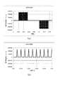
図3はこの指令位置を、差分器241で1回差分(指令速度)した場合の波形である。
FIG. 3 shows a waveform when the command position is differentiated once (command speed) by the
位置の次元では分かりにくかった周期的変動が、指令速度では加減速時にあらわれるようになる。図3(a)は指令速度の全体波形、図3(b)は拡大波形だが、特に加速・減速区間において、指令更新周期1msと同期した階段状の変動が見られる。
Periodic fluctuations that were difficult to understand in the position dimension appear at acceleration / deceleration at the command speed. FIG. 3 (a) shows the entire waveform of the command speed, and FIG. 3 (b) shows an enlarged waveform. In particular, in the acceleration / deceleration section, a step-like fluctuation synchronized with the
図4は差分器241で、指令位置を2回差分(指令加速度)した場合の波形である。
FIG. 4 shows a waveform when the command position is differentiated twice (command acceleration) by the
加速度の次元では、図4(a)のように加速・減速区間でインパルス状の指令が並び、図4(b)で拡大してみると1ms周期であることが顕著に分かるようになる。 In the dimension of acceleration, impulse-like commands are arranged in the acceleration / deceleration section as shown in FIG. 4A, and when it is enlarged in FIG.
図5はこの指令加速度の自己相関関数を算出器242で計算した結果を示す。自己相関関数は正規化することで±1の範囲をとるが、指令加速度が周期性を持つ場合、その周期毎に1に近い値をとるようになる。したがって同定器243で、閾値を例えば0.8あたりに設定して、自己相関関数がこの閾値を越える最小の遅延時間を探索することで、指令更新周期を同定することができる。図5(a)は自己相関関数の全体波形、図5(b)は遅延時間10msまでを拡大した図だが、この例では1msごとに自己相関関数に閾値を超えるピークが得られるため、指令更新周期を1msと同定することができる。
FIG. 5 shows the result of calculating the autocorrelation function of the commanded acceleration by the
なお自己相関関数のピーク値は指令波形によって変動するため、閾値による判定の変わりに、遅延時間が短い方から順番に自己相関関数を計算し、値が最大になったところを指令更新周期としてもよい。この場合、自己相関関数の計算をここで打ち切ることで、計算時間を短縮できる。 Since the peak value of the autocorrelation function varies depending on the command waveform, the autocorrelation function is calculated in order from the one with the shortest delay time instead of the judgment by the threshold value, and the point where the value becomes the maximum is used as the command update cycle Good. In this case, the calculation time can be shortened by terminating the calculation of the autocorrelation function here.
また指令更新周期が制御周期より短い場合には、自己相関関数に明確なピークが現れず、どこまでも計算が続く可能性がある。これを避けるため、指令パターンが含むと想定される最小の繰返し周期から、遅延時間の上限を決めておき、その時点まで計算しても明確なピークがなかった場合には、指令の補間を行わないようにすることで、無駄な計算を省くことができる。 In addition, when the command update cycle is shorter than the control cycle, no clear peak appears in the autocorrelation function, and calculation may continue to any extent. In order to avoid this, the upper limit of the delay time is determined from the minimum repetition period assumed to be included in the command pattern, and if there is no clear peak even if it is calculated up to that point, command interpolation is performed. By avoiding this, useless calculation can be omitted.
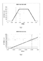
図6は、補間部22を移動平均フィルタとして、移動平均時間を指令更新周期の1msとしたときのフィルタ出力を、指令速度の次元でプロットしたものである。図6(a)の全体波形も、図6(b)の拡大波形を見ても、対応する図3にあった加速・減速区間の階段状の波形がきれいに補間されていうことが分かる。
FIG. 6 is a plot of filter output in the dimension of command speed when the
以上、本発明のモータ駆動装置は、指令更新周期と制御周期の比が分からない場合でも、これを正確に測定し、指令更新周期毎の周期的変動を抑制する手段を提供するものである。 As described above, the motor drive device of the present invention provides means for accurately measuring the ratio of the command update cycle and the control cycle and suppressing periodic fluctuations for each command update cycle.
なお本発明で述べた推定部24は、モータ駆動装置に内蔵する必要は必ずしもなく、モータ駆動装置で受信した指令データを、図示しない通信機能を用いてパソコンなどに転送し、指令更新周期推定部の処理をパソコン上のソフトウェアで実現したうえで、推定結果を再びモータ駆動装置に転送する構成としてもよい。
Note that the
1 上位コントローラ
2 モータ駆動装置
21 受信部
22 補間部
23 制御部
24 推定部
241 差分器
242 算出器
243 同定器
3 モータ
DESCRIPTION OF
Claims (7)
Priority Applications (1)
| Application Number | Priority Date | Filing Date | Title |
|---|---|---|---|
| JP2013056315A JP6060384B2 (en) | 2013-03-19 | 2013-03-19 | Motor drive device |
Applications Claiming Priority (1)
| Application Number | Priority Date | Filing Date | Title |
|---|---|---|---|
| JP2013056315A JP6060384B2 (en) | 2013-03-19 | 2013-03-19 | Motor drive device |
Publications (2)
| Publication Number | Publication Date |
|---|---|
| JP2014183648A JP2014183648A (en) | 2014-09-29 |
| JP6060384B2 true JP6060384B2 (en) | 2017-01-18 |
Family
ID=51701883
Family Applications (1)
| Application Number | Title | Priority Date | Filing Date |
|---|---|---|---|
| JP2013056315A Active JP6060384B2 (en) | 2013-03-19 | 2013-03-19 | Motor drive device |
Country Status (1)
| Country | Link |
|---|---|
| JP (1) | JP6060384B2 (en) |
Families Citing this family (2)
| Publication number | Priority date | Publication date | Assignee | Title |
|---|---|---|---|---|
| JP6983237B2 (en) * | 2016-11-23 | 2021-12-17 | キミドライブ エルエルシーKimidrive Llc | Packet-based networking for variable frequency drives |
| CN112994561B (en) * | 2021-01-26 | 2022-09-23 | 浙江工业大学 | Asynchronous motor rotor resistance and leakage inductance identification method based on correlation function method |
Family Cites Families (4)
| Publication number | Priority date | Publication date | Assignee | Title |
|---|---|---|---|---|
| JPH03258198A (en) * | 1990-03-08 | 1991-11-18 | Takaoka Electric Mfg Co Ltd | Noise elimination system for periodic installation sound |
| JPH06131388A (en) * | 1992-09-03 | 1994-05-13 | Omron Corp | Correlation arithmetic device and voiced sound/unvoiced sound discriminating device |
| JP5259300B2 (en) * | 2008-08-21 | 2013-08-07 | 株式会社日立産機システム | Servo control device |
| JP5202271B2 (en) * | 2008-12-15 | 2013-06-05 | 三菱電機株式会社 | Slave device and program |
-
2013
- 2013-03-19 JP JP2013056315A patent/JP6060384B2/en active Active
Also Published As
| Publication number | Publication date |
|---|---|
| JP2014183648A (en) | 2014-09-29 |
Similar Documents
| Publication | Publication Date | Title |
|---|---|---|
| JP5538529B2 (en) | Motor control device | |
| JP6277428B2 (en) | Motor drive device | |
| JP2007219642A (en) | Control system | |
| JP6544219B2 (en) | Control device | |
| JP2017102617A (en) | Correction device, control method of correction device, information processing program, and record medium | |
| JP2015519740A5 (en) | ||
| US9110455B2 (en) | Numerical control machine | |
| JP6290619B2 (en) | Motor control device | |
| US20160048116A1 (en) | Motor drive device | |
| JPWO2015111298A1 (en) | Motor control device | |
| JP6060384B2 (en) | Motor drive device | |
| JP6491497B2 (en) | Motor control device | |
| JP2015055567A5 (en) | ||
| JP6453576B2 (en) | Motor system | |
| JP2017068625A (en) | Servo control apparatus with function for measuring characteristics of learning controller | |
| JP2016212463A (en) | Controller, control system, control method of controller, control program, and recording medium | |
| CN103633916A (en) | Motor control apparatus | |
| CN110412893B (en) | Method for determining an adjusted guide value of a guide shaft and control assembly | |
| TW201416812A (en) | Servo control device | |
| JP5256704B2 (en) | Moment of inertia estimation device | |
| EP3076260B1 (en) | Device and method for assisting in design improvement work for mechanical device | |
| CN111052029B (en) | Instruction value interpolation device and servo driver | |
| JP6524371B1 (en) | Filtering device, sensor device, filtering method and program | |
| KR20110132640A (en) | Input shaper for non-linear actuators and input shaping method thereof | |
| JP6043191B2 (en) | Motor speed control device |
Legal Events
| Date | Code | Title | Description |
|---|---|---|---|
| A621 | Written request for application examination |
Free format text: JAPANESE INTERMEDIATE CODE: A621 Effective date: 20160205 |
|
| A711 | Notification of change in applicant |
Free format text: JAPANESE INTERMEDIATE CODE: A711 Effective date: 20160314 |
|
| RD01 | Notification of change of attorney |
Free format text: JAPANESE INTERMEDIATE CODE: A7421 Effective date: 20160518 |
|
| TRDD | Decision of grant or rejection written | ||
| A977 | Report on retrieval |
Free format text: JAPANESE INTERMEDIATE CODE: A971007 Effective date: 20161026 |
|
| A01 | Written decision to grant a patent or to grant a registration (utility model) |
Free format text: JAPANESE INTERMEDIATE CODE: A01 Effective date: 20161101 |
|
| A61 | First payment of annual fees (during grant procedure) |
Free format text: JAPANESE INTERMEDIATE CODE: A61 Effective date: 20161114 |
|
| R151 | Written notification of patent or utility model registration |
Ref document number: 6060384 Country of ref document: JP Free format text: JAPANESE INTERMEDIATE CODE: R151 |