JP6060201B2 - Hot water tap - Google Patents
Hot water tap Download PDFInfo
- Publication number
- JP6060201B2 JP6060201B2 JP2015068170A JP2015068170A JP6060201B2 JP 6060201 B2 JP6060201 B2 JP 6060201B2 JP 2015068170 A JP2015068170 A JP 2015068170A JP 2015068170 A JP2015068170 A JP 2015068170A JP 6060201 B2 JP6060201 B2 JP 6060201B2
- Authority
- JP
- Japan
- Prior art keywords
- hole
- inflow hole
- flow path
- valve body
- hot
- Prior art date
- Legal status (The legal status is an assumption and is not a legal conclusion. Google has not performed a legal analysis and makes no representation as to the accuracy of the status listed.)
- Active
Links
- XLYOFNOQVPJJNP-UHFFFAOYSA-N water Substances O XLYOFNOQVPJJNP-UHFFFAOYSA-N 0.000 title claims description 227
- 230000000149 penetrating effect Effects 0.000 claims description 16
- 230000035515 penetration Effects 0.000 claims description 7
- 230000001965 increasing effect Effects 0.000 description 21
- 230000012447 hatching Effects 0.000 description 12
- 239000011347 resin Substances 0.000 description 10
- 229920005989 resin Polymers 0.000 description 10
- 239000000919 ceramic Substances 0.000 description 8
- 238000006073 displacement reaction Methods 0.000 description 7
- 238000012856 packing Methods 0.000 description 5
- 238000000746 purification Methods 0.000 description 5
- 230000000694 effects Effects 0.000 description 4
- 239000000463 material Substances 0.000 description 4
- 239000002184 metal Substances 0.000 description 4
- 229910052751 metal Inorganic materials 0.000 description 4
- 230000002411 adverse Effects 0.000 description 3
- 239000000835 fiber Substances 0.000 description 3
- 238000003780 insertion Methods 0.000 description 3
- 230000037431 insertion Effects 0.000 description 3
- 230000002093 peripheral effect Effects 0.000 description 3
- 238000010586 diagram Methods 0.000 description 2
- 230000002708 enhancing effect Effects 0.000 description 2
- 238000004519 manufacturing process Methods 0.000 description 2
- 239000008213 purified water Substances 0.000 description 2
- 230000015572 biosynthetic process Effects 0.000 description 1
- 150000002739 metals Chemical class 0.000 description 1
- 239000007787 solid Substances 0.000 description 1
Images


Description
本発明は、湯水混合栓に関する。 The present invention relates to a hot and cold water mixing tap.
シングルレバー式の湯水混合水栓が知られている。この湯水混合栓では、レバーハンドルの左右回動操作により、湯と水との切り替え、及び、湯水混合比の調整が可能である。更に、レバーハンドルの前後操作により、吐出量の調整が可能である。 A single-lever hot and cold water faucet is known. With this hot / cold water mixing tap, it is possible to switch between hot water and water and adjust the hot / cold water mixing ratio by rotating the lever handle left and right. Furthermore, the discharge amount can be adjusted by operating the lever handle back and forth.
特開平9−4736号公報には、固定弁体の水流入弁孔の口部を湯流入弁孔側に拡大し、逆に湯流入弁孔の口部を小さくした構成が開示されている。この発明では、ハンドルが正面に来る位置では水流入弁孔のみが混合水流出弁孔に連通される。 Japanese Patent Laid-Open No. 9-4736 discloses a configuration in which the mouth of the water inflow valve hole of the fixed valve body is enlarged toward the hot water inflow valve hole, and conversely, the mouth of the hot water inflow valve hole is made smaller. In the present invention, only the water inflow valve hole communicates with the mixed water outflow valve hole at the position where the handle comes to the front.
固定弁体及び可動弁体の大きさは限られており、それらの弁体に形成される孔の大きさにも制約がある。この制約の中で、吐出量を高めることなどの機能が求められている。 The sizes of the fixed valve body and the movable valve body are limited, and the size of the holes formed in these valve bodies is also limited. Under such restrictions, functions such as increasing the discharge amount are required.
本発明の目的は、機能性に優れた湯水混合栓を提供することにある。 An object of the present invention is to provide a hot and cold water mixing tap excellent in functionality.
本発明に係る好ましい湯水混合栓は、流路孔として、水流入孔及び湯流入孔からなる流入孔と流出孔とを有する固定弁体と、前記水流入孔及び/又は前記湯流入孔と前記流出孔とを連通させる流路形成凹部を有しており、前記固定弁体の上を摺動しうる可動弁体と、前記可動弁体を移動させうるレバーハンドルと、を備えている。この湯水混合栓は、前記レバーハンドルの前後回動により、前記可動弁体と前記固定弁体との相対位置を変化させて、吐出量が調節されるように構成されている。この湯水混合栓は、前記レバーハンドルの左右回動により、前記可動弁体と前記固定弁体との相対位置を変化させて、吐水の温度が調節されるように構成されている。好ましくは、前記流路孔のうちの少なくとも一つが、以下の(a)から(e)の全てを満たす。
(a)前記可動弁体側に開口する上開口と、前記可動弁体とは反対側に開口する下開口とを有しており、前記上開口から前記下開口までを繋いでいる。
(b)前記上開口から前記下開口までの全範囲において上下方向に貫通している上下貫通流路部を有している。
(c)前記上開口から所定距離だけ下側の位置から前記上開口までの上下方向範囲に、前記上下貫通流路よりも横方向に流路を拡張する上拡張部を有する。
(d)前記下開口から所定距離だけ上側の位置から前記下開口までの上下方向範囲に、前記上下貫通流路よりも横方向に流路を拡張する下拡張部を有する。
(e)前記上拡張部の下端位置が、前記下拡張部の上端位置よりも下側に位置する。
A preferred hot and cold water mixing plug according to the present invention includes, as a flow path hole, a fixed valve body having an inflow hole and an outflow hole including a water inflow hole and a hot water inflow hole, the water inflow hole and / or the hot water inflow hole, and the It has a flow path forming recess that communicates with the outflow hole, and includes a movable valve body that can slide on the fixed valve body and a lever handle that can move the movable valve body. The hot and cold water mixing tap is configured such that the discharge amount is adjusted by changing the relative position of the movable valve body and the fixed valve body by rotating the lever handle back and forth. The hot and cold water mixing tap is configured such that the temperature of the discharged water is adjusted by changing the relative position of the movable valve body and the fixed valve body by turning the lever handle left and right. Preferably, at least one of the flow path holes satisfies all of the following (a) to (e).
(A) It has the upper opening opened to the said movable valve body side, and the lower opening opened on the opposite side to the said movable valve body, and has connected from the said upper opening to the said lower opening.
(B) It has an up-and-down penetration channel part penetrated in the up-and-down direction in the whole range from the upper opening to the lower opening.
(C) It has an upper extension part which expands a channel in the horizontal direction rather than the up-and-down penetration channel in the up-and-down direction range from a position below a predetermined distance from the upper opening to the upper opening.
(D) It has a lower extension part which extends a channel in the horizontal direction rather than the up-and-down penetration channel in the up-and-down direction range from a position above a predetermined distance from the lower opening to the lower opening.
(E) The lower end position of the upper extension part is located below the upper end position of the lower extension part.
好ましくは、前記上拡張部は、上記流路孔の孔側面を形成する上拡張内面を有している。好ましくは、前記上拡張内面は、上方にいくに従って、徐々に又は段階的に、前記上下貫通流路部から離れるように変位している。好ましくは、前記上拡張内面は、外方に向かって凹んでいる窪みを有している。なお、この「外方」とは、その上拡張内面が設けられている当該孔の外方を意味する。 Preferably, the upper extension portion has an upper extension inner surface that forms a hole side surface of the flow path hole. Preferably, the upper extended inner surface is displaced away from the upper and lower penetrating flow path portion gradually or stepwise as going upward. Preferably, the upper extended inner surface has a recess that is recessed outward. In addition, this "outside" means the outside of the hole in which the extended inner surface is provided.
好ましくは、前記下拡張部は、上記流路孔の孔側面を形成する下拡張内面を有している。好ましくは、前記下拡張内面は、下方にいくに従って、徐々に又は段階的に、前記上下貫通流路部から離れるように変位している。好ましくは、前記下拡張内面は、外方に向かって凹んでいる窪みを有している。なお、この「外方」とは、その下拡張内面が設けられている当該孔の外方を意味する。 Preferably, the lower extension portion has a lower extension inner surface that forms a hole side surface of the flow path hole. Preferably, the lower extended inner surface is displaced away from the upper and lower through-flow passage portions gradually or stepwise as going downward. Preferably, the lower extended inner surface has a recess that is recessed outward. The “outside” means the outside of the hole in which the lower expanded inner surface is provided.
好ましくは、上記(a)から(e)の全てを満たす前記流路孔が、前記流入孔(水流入孔及び湯流入孔)である。好ましくは、前記流入孔の前記上開口が、前記固定弁体の外方に向かって凸となるように曲がって延びる長孔である。好ましくは、前記流入孔の前記上拡張部が、前記上下貫通流路よりも孔長手方向に流路を拡張している。好ましくは、前記流入孔の前記下拡張部が、前記上下貫通流路よりも弁中心方向に流路を拡張している。 Preferably, the flow path hole that satisfies all of the above (a) to (e) is the inflow hole (water inflow hole and hot water inflow hole). Preferably, the upper opening of the inflow hole is a long hole that bends and extends so as to be convex toward the outside of the fixed valve body. Preferably, the upper extension part of the inflow hole extends the channel in the hole longitudinal direction as compared with the vertical through channel. Preferably, the lower extended portion of the inflow hole extends the flow path in the valve center direction rather than the vertical through flow path.
好ましくは、上記(a)から(e)の全てを満たす前記流路孔が、前記流出孔である。好ましくは、この流出孔の前記上拡張部が、前記上下貫通流路よりも弁中心方向に流路を拡張している。好ましくは、前記流出孔の前記下拡張部が、前記上下貫通流路よりも弁外側方向に流路を拡張している。 Preferably, the flow path hole that satisfies all of the above (a) to (e) is the outflow hole. Preferably, the upper extended portion of the outflow hole extends the flow path in the valve center direction rather than the vertical through flow path. Preferably, the lower extension portion of the outflow hole extends the flow path in the valve outer side direction with respect to the vertical through flow path.
好ましくは、前記(a)から(e)の全てを満たす前記流路孔が、前記流入孔(水流入孔及び湯流入孔)である。好ましくは、この流入孔における前記上下貫通流路部の断面積がS1とされ、この流入孔の最小断面積がS2とされる。好ましくは、S2/S1が1.1以上である。 Preferably, the flow path hole satisfying all of (a) to (e) is the inflow hole (water inflow hole and hot water inflow hole). Preferably, the cross-sectional area of the upper and lower through-flow passage portions in the inflow hole is S1, and the minimum cross-sectional area of the inflow hole is S2. Preferably, S2 / S1 is 1.1 or more.
好ましくは、前記(a)から(e)の全てを満たす前記流路孔が、前記流入孔(水流入孔及び湯流入孔)である。好ましくは、この流入孔の前記上開口が、前記固定弁体の外方に向かって凸となるように曲がって延びる長孔である。この上開口の面積がS3とされ、この流入孔の最小断面積がS2とされる。好ましくは、S3/S2が1.0以上である。 Preferably, the flow path hole satisfying all of (a) to (e) is the inflow hole (water inflow hole and hot water inflow hole). Preferably, the upper opening of the inflow hole is a long hole that bends and extends so as to be convex toward the outside of the fixed valve body. The area of the upper opening is S3, and the minimum cross-sectional area of the inflow hole is S2. Preferably, S3 / S2 is 1.0 or more.
好ましくは、前記(a)から(e)の全てを満たす前記流路孔が、前記流入孔(水流入孔及び湯流入孔)である。好ましくは、この流入孔の前記下開口の面積がS4とされ、この流入孔の最小断面積がS2とされる。好ましくは、S4/S2が1.0以上である。 Preferably, the flow path hole satisfying all of (a) to (e) is the inflow hole (water inflow hole and hot water inflow hole). Preferably, the area of the lower opening of the inflow hole is S4, and the minimum cross-sectional area of the inflow hole is S2. Preferably, S4 / S2 is 1.0 or more.
機能性に優れた湯水混合栓が得られうる。 A hot and cold water mixing tap excellent in functionality can be obtained.
以下、適宜図面が参照されつつ、好ましい実施形態に基づいて本発明が詳細に説明される。 Hereinafter, the present invention will be described in detail based on preferred embodiments with appropriate reference to the drawings.
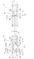
図1は、本発明の一実施形態に係る湯水混合栓10の斜視図である。図2は、湯水混合栓10の上部の正面図である。図3は、湯水混合栓10の上部の側面図である。湯水混合栓10は、本体12、レバーハンドル14、吐出部16、湯導入管18、水導入管20及び吐出管22を有する。吐出部16は、ヘッド24を有する。ヘッド24は、切替レバー26を有する。この切替レバー26の操作により、シャワー吐出と通常吐出との切り替えが可能である。湯水混合栓10は、例えば、キッチン、洗面台等で使用される。
FIG. 1 is a perspective view of a hot and cold
更に、ヘッド24は、切替ボタン28と表示部30を有する。吐出部16には、浄水カートリッジ(図示されず)が内臓されている。切替ボタン28により、浄水カートリッジを透過する流路と、浄水カートリッジを透過しない流路とが切り換えられる。浄水カートリッジを透過する流路に切り換えられると、浄水が吐出される。浄水カートリッジを透過しない流路に切り換えられると、原水が吐出される。表示部30は、吐水が浄水か原水かを表示する。
Further, the
レバーハンドル14の前後回動(上下動)により、レバー前後位置が変化する。レバー前後位置により、吐出量が調整される。本実施形態では、レバーハンドル14を上側に動かすほど、吐出量が増加する。図3のレバーハンドル14の位置は、可動範囲の最も下側(止水位置)である。逆に、レバーハンドル14を下側に動かすほど吐出量が増加してもよい。また、レバーハンドル14の左右回動により、レバー左右位置が変化する。レバー左右位置により、湯と水との混合割合が変化する。レバーハンドル14の左右回動により、吐水の温度調整が可能である。 As the lever handle 14 rotates back and forth (up and down), the lever front and rear position changes. The discharge amount is adjusted according to the lever front-rear position. In the present embodiment, the discharge amount increases as the lever handle 14 is moved upward. The position of the lever handle 14 in FIG. 3 is the lowest side (water stop position) of the movable range. Conversely, the discharge amount may increase as the lever handle 14 is moved downward. Further, the lever left-right position changes as the lever handle 14 rotates left and right. The mixing ratio of hot water and water changes depending on the left / right position of the lever. The temperature of the water discharge can be adjusted by turning the lever handle 14 left and right.
図4は、図2のF4−F4線に沿った断面図である。湯水混合栓10は、その内部に、レバー組立体38を有する。
4 is a cross-sectional view taken along line F4-F4 of FIG. The hot and cold
図5は、レバー組立体38の斜視図である。図6は、レバー軸に対して垂直な断面に沿ったレバー組立体38の断面図である。図7は、レバー軸に沿ったレバー組立体38の断面図である。図8は、レバー組立体38の分解斜視図である。可能である。湯水混合栓10において、レバー組立体38は交換可能である。
FIG. 5 is a perspective view of the
図8等が示すように、レバー組立体38は、移動体40、ハウジング42、回動体44、レバー46、レバー軸48、左右クリック用弾性部材50、左右クリック用当接体52、軸54、前後クリック用当接体56、前後クリック用弾性部材58、可動弁体60、固定弁体62、パッキン64、Oリング66、Oリング67及びベース体68を有する。前述のレバーハンドル14は、レバー46に固定されている。
As shown in FIG. 8 and the like, the
前後クリック用当接体56及び前後クリック用弾性部材58は、移動体40に取り付けられている。前後クリック用当接体56は、前後クリック用弾性部材58(ねじりバネ)に付勢されつつ、前後クリック用係合部59に当接している。前後クリック用係合部59は図7に示されており、レバー46に設けられている。当接体56と前後クリック用係合部59との当接に起因して、レバー46の前後回動に伴うクリック感が生じる。
The front / rear
左右クリック用当接体52及び左右クリック用弾性部材50は、回動体44に取り付けられている。左右クリック用当接体52は、左右クリック用弾性部材50(板バネ)に付勢されつつ、左右クリック用係合部に当接しうる。左右クリック用係合部は図示されていないが、ハウジング42の内面に設けられている。当接体52と左右クリック用係合部との当接に起因して、レバー46の左右回動に伴うクリック感が生じる。
The left-right
ベース体68は、湯導入口70、水導入口72及び吐出口74を有する。ベース体68の下部には、これら湯導入口70、水導入口72及び吐出口74のそれぞれに対応した開口が設けられており、これらの開口のそれぞれに、湯導入管18、水導入管20及び吐出管22が接続されている。
The
固定弁体62は、ベース体68の上側に固定される。ベース体68には、固定弁体62を固定するための係合凸部76と、ハウジング42を固定するための係合凸部77とが設けられている。固定弁体62には、係合凸部76と係合する係合凹部78が設けられている。
The fixed
固定弁体62は、湯流入孔80、水流入孔82及び流出孔84を有する。湯流入孔80は、ベース体68の湯導入口70に接続されている。水流入孔82は、ベース体68の水導入口72に接続されている。流出孔84は、ベース体68の吐出口74に接続されている。
The fixed
可動弁体60は、上側部材86と、下側部材88とを有する。上側部材86は、下側部材88に固定されている。この固定は、凸部90と凹部92との係合によって達成されている。本実施形態では、上側部材86と下側部材88とが互いに別部材である。別部材とすることで、上側部材86と下側部材88とのそれぞれにおいて、最適な材質及び製法が選択されうる。可動弁体60は全体として一体的に成形されていてもよい。
The
図6及び図7が示すように、可動弁体60(下側部材88)の下面には、流路形成凹部94が形成されている。流路形成凹部94は、下方に向かって開口している。流路形成凹部94の上方は閉じている。
As shown in FIGS. 6 and 7, a flow
固定弁体62の上面には、平滑面PL1が設けられている(図8参照)。前記孔80、82及び84が存在していない部分に、平滑面PL1が形成されている。一方、下側部材88(可動弁体60)の下面には、平滑面PL2が設けられている。流路形成凹部94が形成されていない部分に、平滑面PL2が設けられている。平滑面PL1と平滑面PL2との面接触により、水密状態が確保されている。
A smooth surface PL1 is provided on the upper surface of the fixed valve body 62 (see FIG. 8). A smooth surface PL1 is formed in a portion where the
なお、図8が示すように、パッキン64はパイプ状であるが、図7においては、断面位置の関係で、パッキン64が中実であるかのように図示されている。 As shown in FIG. 8, the packing 64 has a pipe shape, but in FIG. 7, the packing 64 is illustrated as being solid due to the cross-sectional position.
上側部材86の上面には、レバー46の下端95と係合するレバー係合凹部98が設けられている。レバー46の下端95は、このレバー係合凹部98に挿入されている(図7参照)。レバー46(レバーハンドル14)の動きに連動して、可動弁体60が固定弁体62の上を摺動する。レバーハンドル14の左右回動に連動して、可動弁体60は回転する。レバーハンドル14の前後回動に連動して、可動弁体60は移動する。
A
なお、レバー46とレバー係合凹部98との係合は、直接的であってもよいし、間接的であってもよい。例えば、レバー46とレバー係合凹部98との間に他の部材が介在していてもよい。
The engagement between the
図8が示すように、レバー46は、軸孔100を有する。この軸孔100に、レバー軸48が挿通されている。
As shown in FIG. 8, the
回動体44は、基部102と上部104とを有する。上部104は、レバー挿入孔106と、軸孔108とを有する。基部102は、可動弁体60(の上側部材86)に、スライド可能に取り付けられている。
The rotating
レバー46がレバー挿入孔106に挿入されており、このレバー46の軸孔100と、回動体44の軸孔108とが同軸で配置されている。これら軸孔100及び軸孔108に、レバー軸48が挿入されている。レバー軸48の挿入により、レバー46が、前後回動可能な状態で、回動体44に固定される。レバー挿入孔106の寸法は、レバー46の前後回動を許容しうるように設定されている。なお本願では、レバー軸48を回転軸とするレバー46の回動及びそれに伴うレバーハンドル14の回動が、「前後回動」とも称される。
The
移動体40は、回動体44に、上下移動が可能な状態で保持されている。移動体40は、回動体44に対して上下移動のみが可能であり、回動体44に対して相対回転することはできない。移動体40は、レバーハンドル14の左右回動に連動して回動体44と共に回転し、且つこの回転に連動して上下移動しうるように構成されている。この移動体40の上下移動は、移動体40とハウジング42との間で形成されたカム機構によって達成されている。移動体40の内面には、凸部110(図7参照)が形成されている。このカム機構は、移動体40に形成された凸部110と、ハウジング42に設けられた溝112(図6、図7及び図8参照)との係合によって構成されている。図8が示すように、この溝112は曲がって延在している。この溝112に沿って凸部110が動くことで、移動体40は回転しながら上下移動する。移動体40が上側に移動すると、前後クリックに係る係合(当接体56と前後クリック用係合部59との係合)が解除される。移動体40が下側に移動すると、前後クリックに係る係合が達成される。
The moving
移動体40は、回動体44に対する相対回転が不要な状態で、回動体44に保持されている。移動体40は、回動体44とともに回転する。レバーハンドル14、レバー46、移動体40及び回動体44は、一緒に回転する。
The moving
図8が示すように、ハウジング42は、小径円筒部120と、大径円筒部122と、連結部124とを有する。連結部124は、ハウジング42の半径方向に延在している。小径円筒部120は、上方開口126を有する。大径円筒部122は、下方開口128を有する。前述の溝112は、小径円筒部120の外周面に設けられている。
As shown in FIG. 8, the
大径円筒部122は、係合孔130を有する。この係合孔130が、ベース体68の係合凸部77と係合している。この係合により、ハウジング42は、ベース体68に固定されている。
The large diameter
回動体44の上部104の円周面部の外径は、小径円筒部120の内径に略等しい。回動体44の上部104は、小径円筒部120に、回転可能な状態で保持されている。この回転では、上部104の外周面と、小径円筒部120の内周面とが摺動する。大径円筒部122は、回動体44の基部102、可動弁体60及び固定弁体62を収容している。
The outer diameter of the circumferential surface portion of the
図9(a)は、可動弁体60の下側部材88の斜視図である。図9(b)は、上下反転された下側部材88の斜視図である。図10(a)は、下側部材88の平面図(上面図)である。図10(b)は、下側部材88の底面図(下面図)である。図11(a)は、図10(b)のA−A線に沿った断面図である。図11(b)は、図10(b)のB−B線に沿った断面図である。
FIG. 9A is a perspective view of the
図11(a)及び図11(b)が示すように、下側部材88は有底の凹部を有しており、この凹部が流路形成凹部94である。このように、本実施形態では、下側部材88のみによって流路形成凹部94が形成されている。2つの部材によって流路形成凹部94が形成されていてもよい。例えば、貫通孔を有する下側部材と、凹部を有する上側部材とによって流路形成凹部94が形成されてもよい。この場合、前記下側部材の前記貫通孔の上側開口を塞ぐように前記上側部材の前記凹部が配置され、これら前記貫通孔と前記凹部とが合体して流路形成凹部94が形成される。
As shown in FIGS. 11A and 11B, the
流路形成凹部94は、下開口線94bを有している。後述されるように、この下開口線94bで囲まれる領域と、固定弁体62の各弁孔の上開口との重なりによって、吐水が実現する。
The flow
図12(a)は、固定弁体62を上側から見た斜視図である。図12(b)は、固定弁体62を下側から見た斜視図である。図13(a)は、固定弁体62の平面図(上面図)である。図13(b)は、固定弁体62の底面図(下面図)である。
FIG. 12A is a perspective view of the fixed
前述のとおり、固定弁体62は、湯流入孔80、水流入孔82及び流出孔84を有する。
As described above, the fixed
湯流入孔80は、上開口線80aを有する。この上開口線80aは、平滑面PL1における湯流入孔80の輪郭線である。上開口線80aは、湯流入孔80の上開口の輪郭線である。図13(a)が示すように、上開口線80aによって画定される上開口は、曲がった長孔である。更に湯流入孔80は、下開口線80bを有する。下開口線80bは、湯流入孔80の下開口の輪郭線である。
The hot
水流入孔82は、上開口線82aを有する。この上開口線82aは、平滑面PL1における水流入孔82の輪郭線である。上開口線82aは、水流入孔82の上開口の輪郭線である。図13(a)が示すように、上開口線82aによって画定される上開口は、曲がった長孔である。更に水流入孔82は、下開口線82bを有する。下開口線82bは、水流入孔82の下開口の輪郭線である。
The
流出孔84は、上開口線84aを有する。この上開口線84aは、平滑面PL1における流出孔84の輪郭線である。上開口線84aは、流出孔84の上開口の輪郭線である。更に、流出孔84は、下開口線84bを有する。下開口線84bは、流出孔84の下開口の輪郭線である。
The
図13(a)が示すように、上開口線80aと上開口線82aとは、互いに左右対称である。図13(b)が示すように、下開口線80bと下開口線82bとは、互いに左右対称である。
As shown in FIG. 13A, the
図13(a)が示すように、流出孔84の上面開口線84aは、左右対称に形成されている。図13(b)が示すように、流出孔84の下開口線84bは、左右対称に形成されている。
As shown in FIG. 13A, the upper
図14(a)は、固定弁体62の側面図である。図14(b)は、図13(a)のA−A線に沿った断面図である。図14(c)は、図13(a)のB−B線に沿った断面図である。図15(a)は、図13(a)のC−C線に沿った断面図である。図15(b)は、図13(a)のD−D線に沿った断面図である。図15(c)は、図13(a)のE−E線に沿った断面図である。
FIG. 14A is a side view of the fixed
図16(a)は、図14(a)のA−A線に沿った断面図である。図16(a)は、固定弁体62の高さの1/4の位置における断面図である。図16(b)は、図14(a)のB−B線に沿った断面図である。図16(b)は、固定弁体62の高さの1/2の位置における断面図である。図16(c)は、図14(a)のC−C線に沿った断面図である。図16(c)は、固定弁体62の高さの3/4の位置における断面図である。
FIG. 16A is a cross-sectional view taken along line AA in FIG. FIG. 16A is a cross-sectional view at a position of ¼ of the height of the fixed
図14(a)から図16(c)が示すように、固定弁体62を構成する各孔80、82、84は、複雑な形状を呈している。
As shown in FIGS. 14A to 16C, the
本願では、「流入孔」との文言が用いられる。この流入孔は、湯流入孔80及び水流入孔82を含む概念である。
In the present application, the term “inflow hole” is used. This inflow hole is a concept including a hot
本願では、「流路孔」との文言が用いられる。この流路孔は、流入孔80,82及び流出孔84を含む概念である。固定弁体62は、これらの流路孔80,82,84を有している。
In the present application, the term “channel hole” is used. This channel hole is a concept including inflow holes 80 and 82 and an
図17(a)、図17(b)及び図17(c)は、各流路孔80,82,84と流路形成凹部94との重なり状態を示す。これら図17(a)、図17(b)及び図17(c)において、可動弁体60の下側部材88の下面線が破線で描かれており、下側部材88の下にある固定弁体62が実線で描かれている。これらの図において、流路形成凹部94の下開口と流入孔80,82の上開口との重なり領域R1が、ハッチングで示されている。
FIGS. 17A, 17B, and 17C show the overlapping state of each
図17(a)では、レバー左右位置が水側限界(右側限界)であり、レバー前後位置が最大吐出位置である。この状態において、上記重なり領域R1は、水流入孔82と流路形成凹部94との間でのみ生ずる。この状態では、水のみ(水100%)が吐出される。
In FIG. 17A, the lever left-right position is the water limit (right limit), and the lever front-rear position is the maximum discharge position. In this state, the overlapping region R <b> 1 occurs only between the
図17(b)では、レバー左右位置が正面位置であり、レバー前後位置が最大吐出位置である。この状態において、上記重なり領域R1は、水流入孔82と流路形成凹部94との間でのみ生ずる。この状態でも、水のみ(水100%)が吐出される。湯水混合栓10では、レバー左右位置が正面であるとき、水のみ(水100%)が吐出される。レバー左右位置が正面であるときに水のみが吐出されるように、下開口線94bの形状は左右非対称とされている。湯水混合栓10は、節湯性及び省エネルギー性に優れる。
In FIG. 17B, the lever left-right position is the front position, and the lever front-rear position is the maximum discharge position. In this state, the overlapping region R <b> 1 occurs only between the
図17(c)では、レバー左右位置が湯側限界(左限界)であり、レバー前後位置が最大吐出位置である。この状態において、上記重なり領域R1は、湯流入孔80と流路形成凹部94との間でのみ生ずる。この状態では、湯のみ(湯100%)が吐出される。湯100%の吐出は、この図17(c)の状態でのみ生ずる。すなわち、レバー左右位置が湯側限界よりも水側にあるとき、湯と水とが混合されるか、又は、水のみが吐出される。
In FIG. 17C, the lever left-right position is the hot water side limit (left limit), and the lever front-rear position is the maximum discharge position. In this state, the overlapping region R <b> 1 occurs only between the hot
このように、湯水混合栓10は、レバーハンドル14の左右回動により、可動弁体60と固定弁体62との相対位置を変化させて、吐水の温度が調節されるように構成されている。湯水混合栓10は、前記レバーハンドルの前後回動により可動弁体60と固定弁体62との相対位置を変化させて、吐出量が調節されるように構成されている。
As described above, the hot and cold
図18(a)は、図13(a)と同じく、固定弁体62の上面図である。図19(a)も、固定弁体62の上面図である。図18(b)は、図13(b)と同様に、固定弁体62の下面図である。図19(b)も、固定弁体62の下面図である。図20は、図18(a)のA−A線に沿った断面図である。図21(a)は、図14(c)と同じく、図13(a)のB−B線に沿った断面図である。図21(b)は、図15(a)と同じく、図13(a)のC−C線に沿った断面図である。図22(a)は、図21(a)と同じく、図13(a)のB−B線に沿った断面図である。図22(b)は、図14(b)と同じく、図13(a)のA−A線に沿った断面図である。
FIG. 18A is a top view of the fixed
本願では、「上下貫通流路部」との文言が用いられる。この上下貫通流路部は、孔の上開口から下開口までの全範囲において上下方向に貫通している部分を意味する。上下方向とは、平滑面PL1に対して垂直な方向である。図20において一点鎖線ハッチングで示されている部分が、上下貫通流路部P1である。 In the present application, the term “upper and lower through flow channel portion” is used. The vertical through-flow passage portion means a portion penetrating in the vertical direction in the entire range from the upper opening to the lower opening of the hole. The vertical direction is a direction perpendicular to the smooth surface PL1. In FIG. 20, the portion indicated by the alternate long and short dash line hatching is the vertical penetrating flow path portion P1.
したがって、上下貫通流路部P1は、上面図(平面図)及び下面図(底面図)において、貫通孔として視認される。図18(a)の上面図において、上下貫通流路部P1は、上面から下面まで貫通した孔として描かれる。図18(b)の下面図においても同様に、上下貫通流路部P1は、下面から上面まで貫通した孔として描かれる。 Therefore, the upper and lower through flow passage portions P1 are visually recognized as through holes in the top view (plan view) and the bottom view (bottom view). In the top view of FIG. 18A, the vertical through-flow passage portion P1 is drawn as a hole penetrating from the upper surface to the lower surface. Similarly, in the bottom view of FIG. 18B, the vertical through-flow passage portion P1 is drawn as a hole penetrating from the bottom surface to the top surface.
図20、図21(a)及び図21(b)が示すように、上下貫通流路部P1は、境界面Lpを有する。境界面Lpは、上下方向に延在し且つ孔側面に内接する面である。上下貫通流路部P1は、境界面Lpの内側の空間である。 As shown in FIG. 20, FIG. 21 (a) and FIG. 21 (b), the vertical penetrating flow path portion P1 has a boundary surface Lp. The boundary surface Lp is a surface extending in the vertical direction and inscribed in the hole side surface. The vertical through-flow passage portion P1 is a space inside the boundary surface Lp.
本願では、「上拡張部」との文言が用いられる。この上拡張部は、前記上開口から所定距離だけ下側の位置から前記上開口までの上下方向範囲に位置し、上下貫通流路部E1よりも横方向に流路を拡張する部分である。この「横方向」とは、上下方向に対して垂直なあらゆる方向を意味する。図19(a)及び図20において破線ハッチングで示されている部分が、上拡張部E1である。 In the present application, the term “upper extension” is used. The upper extension portion is a portion that is positioned in a vertical range from a position below the upper opening by a predetermined distance to the upper opening, and that extends the flow passage in a lateral direction from the vertical through flow passage portion E1. The “lateral direction” means any direction perpendicular to the vertical direction. In FIG. 19 (a) and FIG. 20, the portion indicated by the broken line hatching is the upper extension E1.
上拡張部E1は、上記流路孔の孔側面を形成する上拡張内面m1を有している(図20及び図21(b)参照)。上拡張部E1は、上拡張内面m1と境界面Lpとによって画定される部分である。図19(a)において破線ハッチングで示されている面が、上拡張内面m1である。本実施形態では上拡張内面m1の全てが上面図に現れているが、上拡張内面m1の一部が上面図に現れない実施形態も可能である。例えば、上拡張内面m1の一部が、上方から視認されない湾曲面であってもよい。円滑な流れの観点から、上拡張内面m1の全てが上面図に現れるのが好ましい。 The upper extension portion E1 has an upper extension inner surface m1 that forms the hole side surface of the flow path hole (see FIGS. 20 and 21B). The upper extension E1 is a part defined by the upper extension inner surface m1 and the boundary surface Lp. A surface indicated by broken line hatching in FIG. 19A is the upper expanded inner surface m1. In the present embodiment, all of the upper extended inner surface m1 appears in the top view, but an embodiment in which a part of the upper extended inner surface m1 does not appear in the top view is possible. For example, a part of the upper extended inner surface m1 may be a curved surface that is not visible from above. From the viewpoint of smooth flow, it is preferable that all of the upper extended inner surface m1 appear in the top view.
図19(a)の上面図において、上拡張部E1は、上側から見える孔側面(斜面)の上方の空間である。 In the top view of FIG. 19A, the upper extension E1 is a space above the hole side surface (slope) seen from above.
本願では、「下拡張部」との文言が用いられる。この下拡張部は、前記下開口から所定距離だけ上側の位置から前記下開口までの上下方向範囲に位置し、前記上下貫通流路よりも横方向に流路を拡張する部分である。図21(a)等において破線ハッチングで示されている部分が、下拡張部E2である。 In the present application, the term “lower extension” is used. The lower extension portion is a portion that is located in a vertical range from a position that is a predetermined distance above the lower opening to the lower opening, and that extends the flow path in a lateral direction from the vertical through flow path. A portion indicated by broken line hatching in FIG. 21A or the like is the lower extension portion E2.
下拡張部E2は、上記流路孔の孔側面を形成する下拡張内面m2を有している(図21(a)参照)。上拡張部E2は、下拡張内面m2と境界面Lpとによって画定される部分である。図19(b)において破線ハッチングで示されている面が、下拡張内面m2である。本実施形態では下拡張内面m2の全てが下面図に現れているが、下拡張内面m2の一部が下面図に現れない実施形態も可能である。例えば、下拡張内面m2の一部が、下方から視認されない湾曲面であってもよい。円滑な流れの観点から、下拡張内面m2の全てが下面図に現れるのが好ましい。 The lower extension portion E2 has a lower extension inner surface m2 that forms the hole side surface of the flow path hole (see FIG. 21A). The upper extension portion E2 is a portion defined by the lower extension inner surface m2 and the boundary surface Lp. A surface indicated by broken line hatching in FIG. 19B is a lower expanded inner surface m2. In the present embodiment, all of the lower extended inner surface m2 appears in the bottom view, but an embodiment in which a part of the lower extended inner surface m2 does not appear in the bottom view is also possible. For example, a part of the lower extended inner surface m2 may be a curved surface that is not visible from below. From the viewpoint of smooth flow, it is preferable that all of the lower extended inner surface m2 appear in the bottom view.
なお、図20においてドット(散点)で示されている部分は、パッキン64によって占められる部分であるから、下拡張部E2ではない。 In addition, since the part shown by the dot (scattered dot) in FIG. 20 is a part occupied by the packing 64, it is not the lower extension part E2.
図19(b)の下面図において、下拡張部E2は、下側から見える孔側面(斜面)の下方の空間である。 In the bottom view of FIG. 19B, the lower extension E2 is a space below the hole side surface (slope) that can be seen from the lower side.
好ましくは、流路孔80,82,84のうちの少なくとも一つが、以下の(a)から(e)の全てを満たしている。
(a)可動弁体60側に開口する上開口と、可動弁体60とは反対側に開口する下開口とを有しており、前記上開口から前記下開口までを繋いでいる。
(b)前記上開口から前記下開口までの全範囲において上下方向に貫通している上下貫通流路部P1を有している。
(c)前記上開口から所定距離だけ下側の位置から前記上開口までの上下方向範囲に、上下貫通流路部P1よりも横方向に流路を拡張する上拡張部E1を有する。
(d)前記下開口から所定距離だけ上側の位置から前記下開口までの上下方向範囲に、上下貫通流路部P1よりも横方向に流路を拡張する下拡張部E2を有する。
(e)上拡張部E1の下端位置が、下拡張部E2の上端位置よりも下側に位置する。
Preferably, at least one of the flow path holes 80, 82, 84 satisfies all of the following (a) to (e).
(A) It has the upper opening opened to the
(B) It has the up-and-down penetration flow path part P1 penetrated to the up-down direction in the whole range from the said upper opening to the said lower opening.
(C) An upper expansion portion E1 that extends the flow path in the lateral direction from the vertical through flow path portion P1 is provided in a vertical range from a position below the upper opening by a predetermined distance to the upper opening.
(D) A lower expansion portion E2 is provided in the vertical range from the position above the lower opening by a predetermined distance to the lower opening to expand the flow channel in the lateral direction with respect to the vertical penetrating flow passage portion P1.
(E) The lower end position of the upper extension part E1 is located below the upper end position of the lower extension part E2.
湯水混合栓10では、湯流入孔80及び水流入孔82が、上記(a)から(e)の全てを満たしている。
In the hot-
湯流入孔80に関して、上記(a)から(e)の充足性を説明する。図18(a)、図18(b)及び図20が示すように、湯流入孔80は、上下貫通流路部P1としての上下貫通流路部P10を有する。図19(a)、図20及び図21(b)が示すように、湯流入孔80は、上拡張部E1としての上拡張部E10を有する。図19(b)及び図21(a)が示すように、湯流入孔80は、下拡張部E2としての下拡張部E20を有する。従って、湯流入孔80は、上記(a)、(b)、(c)及び(d)を満たしている。
With regard to the hot
図21(a)と図21(b)との組み合わせが示すように、上拡張部E10の下端位置btが、下拡張部E20の上端位置tpよりも下側に位置している。換言すれば、上拡張部E10と下拡張部E20とは、上下方向位置において互いに重複する重複部Tfを有する。従って、湯流入孔80は、上記(e)をも満たしている。このように、湯流入孔80は、上記(a)から(e)の全てを満たす。
As shown in the combination of FIG. 21A and FIG. 21B, the lower end position bt of the upper extension portion E10 is located below the upper end position tp of the lower extension portion E20. In other words, the upper extension portion E10 and the lower extension portion E20 have an overlapping portion Tf that overlaps each other in the vertical position. Therefore, the hot
水流入孔82に関して、上記(a)から(e)の充足性を説明する。図18(a)、図18(b)及び図20が示すように、水流入孔82は、上下貫通流路部P1としての上下貫通流路部P12を有する。図19(a)及び図20が示すように、水流入孔82は、上拡張部E1としての上拡張部E12を有する。図19(b)及び図21(a)が示すように、水流入孔82は、下拡張部E2としての下拡張部E22を有する。従って、水流入孔82は、上記(a)、(b)、(c)及び(d)を満たしている。
With respect to the
図20が示すように、水流入孔82における上拡張部E12の下端位置btは、湯流入孔80の下端位置btと同じである。よって、図21(a)と図21(b)との組み合わせから類推できるように、上拡張部E12の下端位置btが、下拡張部E22の上端位置tpよりも下側に位置している。換言すれば、上拡張部E12と下拡張部E22とは、上下方向位置において互いに重複する重複部Tfを有する。なお、水流入孔82の上拡張部E12の下端位置btの上下方向位置は、図21(b)で示される上拡張部E10の下端位置btの上下方向位置に等しい。従って、水流入孔82は、上記(e)をも満たしている。このように、水流入孔82は、上記(a)から(e)の全てを満たす。
As shown in FIG. 20, the lower end position bt of the upper extension E12 in the
更に、湯水混合栓10では、流出孔84が、上記(a)から(b)の全てを満たしている。
Furthermore, in the hot and cold
流出孔84に関して、上記(a)から(e)の充足性を説明する。図18(a)及び図18(b)が示すように、流出孔84は、上下貫通流路部P1としての上下貫通流路部P14を有する。図19(a)及び図22(b)が示すように、流出孔84は、上拡張部E1としての上拡張部E14を有する。図19(b)及び図22(b)が示すように、流出孔84は、下拡張部E2としての下拡張部E24を有する。従って、流出孔84は、上記(a)、(b)、(c)及び(d)を満たしている。
With respect to the
図22(b)が示すように、上拡張部E14の下端位置btが、下拡張部E24の上端位置tpよりも下側に位置している。換言すれば、上拡張部E14と下拡張部E24とは、上下方向位置において互いに重複する重複部Tfを有する。従って、流出孔84は、上記(e)をも満たしている。このように、流出孔84は、上記(a)から(e)の全てを満たす。
As shown in FIG. 22B, the lower end position bt of the upper extension part E14 is located below the upper end position tp of the lower extension part E24. In other words, the upper extension portion E14 and the lower extension portion E24 have an overlapping portion Tf that overlaps each other in the vertical position. Therefore, the
図21(a)が示すように、湯流入孔80の下拡張部E20の一部は、流出孔84の上拡張部E14の下側に位置する。また、水流入孔82の下拡張部E22の一部は、流出孔84の上拡張部E14の下側に位置する。このように、上拡張部E1の下側に下拡張部E2の一部が位置している。この配置により、限られた大きさの固定弁体62において、上拡張部E1及び下拡張部E2の断面積が確保されうる。これは、流量の増大に寄与する。
As shown in FIG. 21A, a part of the lower extended portion E20 of the hot
図22(a)と図22(b)との対比から明らかなように、流出孔84の上拡張部E14の下端位置btは、湯流入孔80の下拡張部E20の上端位置tpよりも下側に位置している。また、流出孔84の上拡張部E14の下端位置btは、水流入孔82の下拡張部E22の上端位置tpよりも下側に位置している。
22A and 22B, the lower end position bt of the upper extended portion E14 of the
流量(流入量及び流出量)を増大させるためには、流路孔の断面積を大きくする必要がある。一方、固定弁体62の上開口の形状及び位置は、可動弁体60の流路形成凹部94の形状、可動弁体60の移動範囲、固定弁体62の流出孔84の形状などの制約を受ける(制約1)。また、固定弁体62の下開口の形状及び位置は、固定弁体62の下部に接続される部材の流路の形状及び位置によって制約される(制約2)。これらの制約に起因して、流量の増大には課題があった。
In order to increase the flow rate (inflow and outflow), it is necessary to increase the cross-sectional area of the channel hole. On the other hand, the shape and position of the upper opening of the fixed
上記(a)から(e)を満たす場合、上開口については、上記制約1のみを考慮してその面積を拡大することができ、更に上拡張部E1により流量の増大が可能となる。また下開口については、上記制約2のみを考慮してその面積を拡大することができ、更に下拡張部E2により流量の増大が可能となる。
When the above (a) to (e) are satisfied, the area of the upper opening can be expanded in consideration of only the
[T2/T1]
図21(a)、図21(b)及び図22(b)において両矢印T1で示されているのは、流路孔の上下方向長さである。図21(a)、図21(b)及び図22(b)において両矢印T2で示されているのは、上拡張部E1と下拡張部E2との上記重複部Tfの上下方向長さである。各流路孔(湯流入孔80、水流入孔82及び流出孔84)のそれぞれについて、比(T2/T1)が設定されるのが好ましい。
[T2 / T1]
In FIG. 21A, FIG. 21B, and FIG. 22B, what is indicated by a double-headed arrow T1 is the vertical length of the channel hole. In FIGS. 21A, 21B, and 22B, the double arrow T2 indicates the vertical length of the overlapping portion Tf of the upper extension portion E1 and the lower extension portion E2. is there. The ratio (T2 / T1) is preferably set for each flow path hole (hot
上記要件(e)に起因して、上述の制約の下であっても孔流路の断面積を全体として拡大することができ、流量の増大が可能となる(拡張部重複効果)。この観点から、T2/T1は、0.03以上が好ましく、0.1以上がより好ましく、0.15以上がより好ましい。T2/T1が過大である場合、上拡張部E1の下側の肉厚が小さくなったり、下拡張部E2の上側の肉厚が小さくなったりして、耐久性が低下することがある。この観点から、T2/T1は、0.7以下が好ましく、0.5以下がより好ましく、0.4以下がより好ましい。 Due to the requirement (e), the cross-sectional area of the hole channel can be enlarged as a whole even under the above-described restrictions, and the flow rate can be increased (expansion portion overlapping effect). In this respect, T2 / T1 is preferably equal to or greater than 0.03, more preferably equal to or greater than 0.1, and still more preferably equal to or greater than 0.15. When T2 / T1 is excessive, the thickness on the lower side of the upper extension portion E1 may be reduced, or the thickness on the upper side of the lower extension portion E2 may be reduced, thereby reducing durability. In this respect, T2 / T1 is preferably equal to or less than 0.7, more preferably equal to or less than 0.5, and still more preferably equal to or less than 0.4.
なお、上記実施形態において、湯流入孔80のT2/T1は0.3であり、水流入孔82のT2/T1は0.3であり、流出孔84のT2/T1は0.04であった。
In the above embodiment, T2 / T1 of the hot
長さT1が過小である場合、長さT2の確保が困難となることがある。加えて、固定弁体62の耐久性が低下しうる。これらの観点から、流路孔の上下方向長さT1は、5mm以上が好ましく、6mm以上がより好ましく、6.5mm以上がより好ましい。バルブ及び水栓10の大型化を防止する観点から、長さT1は、15mm以下が好ましく、10mm以下がより好ましく、8mm以下がより好ましい。
When the length T1 is too small, it may be difficult to ensure the length T2. In addition, the durability of the fixed
なお、上記実施形態において、湯流入孔80の長さT1は6.8mmであり、水流入孔82の長さT1は6.8mmであり、流出孔84の長さT1は6.8mmであった。
In the above embodiment, the length T1 of the hot
[上拡張内面の形状]
図20及び図21(b)が示すように、湯流入孔80の上拡張内面m1は、上方にいくに従って、徐々に、上下貫通流路部P10から離れるように変位している。すなわち、境界面Lpと上拡張内面m1との距離(横方向距離)が、上方にいくに従って、徐々に大きくなっている。この変位は、段階的であってもよい。すなわち、上拡張内面m1は、上方にいくに従って、段階的に、上下貫通流路部P10から離れるように変位していてもよい。
[Shape of upper extension inner surface]
As shown in FIGS. 20 and 21 (b), the upper expanded inner surface m1 of the hot
図20が示すように、水流入孔82の上拡張内面m1は、上方にいくに従って、徐々に、上下貫通流路部P12から離れるように変位している。すなわち、境界面Lpと上拡張内面m1との距離(横方向距離)が、上方にいくに従って、徐々に大きくなっている。この変位は、段階的であってもよい。すなわち、上拡張内面m1は、上方にいくに従って、段階的に、上下貫通流路部P12から離れるように変位していてもよい。
As shown in FIG. 20, the upper extended inner surface m <b> 1 of the
図22(b)が示すように、流出孔84の上拡張内面m1は、上方にいくに従って、徐々に、上下貫通流路部P14から離れるように変位している。すなわち、境界面Lpと上拡張内面m1との距離(横方向距離)が、上方にいくに従って、徐々に大きくなっている。この変位は、段階的であってもよい。すなわち、上拡張内面m1は、上方にいくに従って、段階的に、上下貫通流路部P14から離れるように変位していてもよい。
As shown in FIG. 22B, the upper extended inner surface m1 of the
図20において符号L1で示されているのは、湯流入孔80の上拡張内面m1の断面線の両端を結ぶ直線である。上拡張内面m1は、この直線L1よりも外方(湯流入孔80の外方)に位置している。すなわち、上拡張内面m1の全体が、外方に向かって凹んでいる窪みを形成している。この窪みは、断面積を増大させる。流量を高める観点から、湯流入孔80の上拡張内面m1は、外方に向かって凹んでいる窪みを有しているのが好ましい。
In FIG. 20, what is indicated by a symbol L <b> 1 is a straight line connecting both ends of the cross-sectional line of the upper expanded inner surface m <b> 1 of the hot
水流入孔82についても同様である。図20が示すように、水流入孔82の上拡張内面m1の全体が、外方(水流入孔82の外方)に向かって凹んでいる窪みを形成している。この窪みは、断面積を増大させる。流量を高める観点から、水流入孔82の上拡張内面m1は、外方に向かって凹んでいる窪みを有しているのが好ましい。
The same applies to the
流出孔84についても同様である。図22(b)が示すように、流出孔84の上拡張内面m1の全体が、外方(流出孔84の外方)に向かって凹んでいる窪みを形成している。この窪みは、断面積を増大させる。流量を高める観点から、流出孔84の上拡張内面m1は、外方に向かって凹んでいる窪みを有しているのが好ましい。
The same applies to the
このように、流路孔(湯流入孔80、水流入孔82及び流出孔84)のそれぞれにおいて、上拡張内面m1は、流路抵抗を抑制しうる形状を有している。すなわち、上述したような上拡張内面m1の変位により、流路抵抗が抑制され、流量が増大しうる。流路抵抗を抑制する観点から、上述の「段階的」よりも、「徐々に」が好ましい。すなわち、上拡張内面m1は、上方にいくに従って、徐々に、上下貫通流路部P1から離れるように変位しているのが好ましい。上拡張内面m1は、滑らかな曲面及び/又は平面で構成されているのが好ましく、滑らかな曲面又は平面で構成されているのがより好ましい。
Thus, in each of the flow path holes (the hot
[下拡張内面m2の形状]
前述の通り、湯流入孔80の下拡張部E20は、流路孔の孔側面を形成する下拡張内面m2を有している(図21(a)参照)。下拡張内面m2は、下方にいくに従って、徐々に、上下貫通流路部P10から離れるように変位している。すなわち、境界面Lpと下拡張内面m2との距離(横方向距離)が、下方にいくに従って、徐々に大きくなっている。この変位は、段階的であってもよい。すなわち、下拡張内面m2は、下方にいくに従って、段階的に、上下貫通流路部P10から離れるように変位していてもよい。
[Shape of lower expanded inner surface m2]
As described above, the lower expanded portion E20 of the hot
前述の通り、水流入孔82の下拡張部E22は、流路孔の孔側面を形成する下拡張内面m2を有している(図21(a)参照)。下拡張内面m2は、下方にいくに従って、徐々に、上下貫通流路部P12から離れるように変位している。すなわち、境界面Lpと下拡張内面m2との距離(横方向距離)が、下方にいくに従って、徐々に大きくなっている。この変位は、段階的であってもよい。すなわち、下拡張内面m2は、下方にいくに従って、段階的に、上下貫通流路部P12から離れるように変位していてもよい。
As described above, the lower extended portion E22 of the
図21(a)において符号L2で示されているのは、湯流入孔80の下拡張内面m2の断面線の両端を結ぶ直線である。下拡張内面m2は、この直線L2よりも外側(湯流入孔80の外方)に位置している。すなわち、下拡張内面m2の全体が、外方に向かって凹んでいる窪みを形成している。このように、湯流入孔80の下拡張内面m2は、外方に向かって凹んでいる窪みを有しているのが好ましい。
In FIG. 21A, what is indicated by a symbol L2 is a straight line connecting both ends of the cross-sectional line of the lower expanded inner surface m2 of the hot
水流入孔82についても同様である。図21(a)が示すように、水流入孔82の下拡張内面m2の全体が、外方(水流入孔82の外方)に向かって凹んでいる窪みを形成している。このように、水流入孔82の下拡張内面m2は、外方に向かって凹んでいる窪みを有しているのが好ましい。
The same applies to the
流出孔84についても同様である。図22(b)が示すように、流出孔84の下拡張内面m2の全体が、外方(流出孔84の外方)に向かって凹んでいる窪みを形成している。このように、流出孔84の下拡張内面m2は、外方に向かって凹んでいる窪みを有しているのが好ましい。
The same applies to the
このように、流路孔(湯流入孔80、水流入孔82及び流出孔84)のそれぞれにおいて、下拡張内面m2は、流路抵抗を抑制しうる形状を有している。すなわち、上述したような下拡張内面m2の変位により、流路抵抗が抑制され、流量が増大しうる。流路抵抗を抑制する観点から、上述の「段階的」よりも、「徐々に」が好ましい。すなわち、下拡張内面m2は、下方にいくに従って、徐々に、上下貫通流路部P1から離れるように変位しているのが好ましい。下拡張内面m2は、滑らかな曲面及び/又は平面で構成されているのが好ましく、滑らかな曲面又は平面で構成されているのがより好ましい。
Thus, in each of the flow path holes (the hot
[湯流入孔80の形状]
図13(a)が示すように、湯流入孔80の上開口は、固定弁体62の外方に向かって凸となるように曲がって延びる長孔である。この上開口は、レバーハンドル14の左右回動に伴う可動弁体60の回転方向に沿って延びている。図19(a)と図18(a)との対比から明らかなように、湯流入孔80の上拡張部E10は、上下貫通流路部P10よりも孔長手方向に流路を拡張している。換言すれば、上拡張部E10は、湯流入孔80の長手方向を延長するように設けられている。一方、図19(b)と図18(b)との対比から明らかなように、湯流入孔80の下拡張部E20は、上下貫通流路部P10よりも弁中心方向に流路を拡張している。弁中心方向とは、固定弁体62の中心に向かう方向である。図16(a)から(c)の対比において、湯流入孔80の下拡張内面m2が下方に行くほど弁中心方向に変位しているのが分かる。このような形状により、上述の制約に対して悪影響を与えることなく、湯流入孔80の流路を拡大することができる。
[Shape of hot water inflow hole 80]
As shown in FIG. 13A, the upper opening of the hot
[水流入孔82の形状]
図13(a)が示すように、水流入孔82の上開口は、固定弁体62の外方に向かって凸となるように曲がって延びる長孔である。この上開口は、レバーハンドル14の左右回動に伴う可動弁体60の回転方向に沿って延びている。図19(a)と図18(a)との対比から明らかなように、水流入孔82の上拡張部E12は、上下貫通流路部P12よりも孔長手方向に流路を拡張している。換言すれば、上拡張部E12は、水流入孔82の長手方向を延長するように設けられている。一方、図19(b)と図18(b)との対比から明らかなように、水流入孔82の下拡張部E22は、上下貫通流路部P12よりも弁中心方向に流路を拡張している。図16(a)から(c)の対比において、水流入孔82の下拡張内面m2が下方に行くほど弁中心方向に変位しているのが分かる。このような形状により、上述の制約に対して悪影響を与えることなく、水流入孔82の流路を拡大することができる。
[Shape of water inflow hole 82]
As shown in FIG. 13A, the upper opening of the
[流出孔84の形状]
図19(a)と図18(a)との対比から明らかなように、流出孔84の上拡張部E14は、上下貫通流路部P14よりも弁中心方向に流路を拡張している。一方、図19(b)と図18(b)との対比から明らかなように、流出孔84の下拡張部E24は、上下貫通流路部P14よりも弁外側方向に流路を拡張している。弁外側方向とは、固定弁体62の外側に向かう方向である。このような形状により、上述の制約に対して悪影響を与えることなく、流出孔84の流路を拡大することができる。
[Shape of Outlet Hole 84]
As is clear from the comparison between FIG. 19A and FIG. 18A, the upper expansion portion E14 of the
[S2/S1]
上記流入孔(湯流入孔80及び水流入孔82のそれぞれ)において、断面積S1が定義される。断面積S1は、上下貫通流路部P1の断面積である。断面積S1は、上下方向に対して垂直な平面による断面において測定される。断面積S1は、上下方向位置に関わらず一定である。
[S2 / S1]
A cross-sectional area S1 is defined in the inflow hole (each of the hot
上記流入孔(湯流入孔80及び水流入孔82のそれぞれ)において、最小断面積S2が定義される。流入孔の断面積は、上下方向位置によって変化している。最小断面積S2は、流入孔の断面積のうちの最小値である。最小断面積S2も、上下方向に対して垂直な平面において測定される。
In the inflow hole (each of the hot
S2/S1が小さくなると、その流入孔はストレート孔に近くなる。この場合、上述の制約の回避が困難となり、固定弁体62等の弁体が大型となりやすい。よって水栓も大型となりやすい。上述の制約を回避し、弁体を小型とする観点から、S2/S1は、1.0以上が好ましく、1.1以上がより好ましく、1.2以上がより好ましい。
When S2 / S1 becomes small, the inflow hole becomes close to a straight hole. In this case, it is difficult to avoid the above-described restrictions, and the valve body such as the fixed
S2/S1を大きくするには以下の手段が考えられるが、各手段には以下のような課題がある。
(a)上拡張部E1の断面積を大きくすることで、S2/S1が大きくなりうるが、この場合、上開口の断面積が大きくなる。上開口の断面積は、上述の制約によって制限される。
(b)下拡張部E2の断面積を大きくすることで、S2/S1が大きくなりうるが、この場合、下開口の断面積が大きくなる。下開口の断面積は、上述の制約によって制限される。
(c)上拡張部E1をより下方まで延長することで、S2/S1が大きくなりうるが、この場合、上拡張部E1の下側に位置する部分の肉厚が小さくなり、耐久性が低下しうる。
(d)下拡張部E2をより上方まで延長することで、S2/S1が大きくなりうるが、この場合、下拡張部E2の下側に位置する部分の肉厚が小さくなり、耐久性が低下しうる。
The following means can be considered to increase S2 / S1, but each means has the following problems.
(A) S2 / S1 can be increased by increasing the cross-sectional area of the upper extension E1, but in this case, the cross-sectional area of the upper opening is increased. The cross-sectional area of the upper opening is limited by the above constraints.
(B) S2 / S1 can be increased by increasing the cross-sectional area of the lower extension E2, but in this case, the cross-sectional area of the lower opening is increased. The cross-sectional area of the lower opening is limited by the above constraints.
(C) By extending the upper extension E1 further downward, S2 / S1 can be increased, but in this case, the thickness of the portion located on the lower side of the upper extension E1 is reduced and the durability is lowered. Yes.
(D) By extending the lower extension E2 further upward, S2 / S1 can be increased, but in this case, the thickness of the portion located on the lower side of the lower extension E2 is reduced and the durability is lowered. Yes.
これらの点を考慮すると、S2/S1は、1.5以下が好ましく、1.45以下がより好ましく、1.4以下がより好ましい。 Considering these points, S2 / S1 is preferably 1.5 or less, more preferably 1.45 or less, and more preferably 1.4 or less.
なお、本実施形態のS2/S1は、1.35であった。 In addition, S2 / S1 of this embodiment was 1.35.
湯水混合栓10の大型化を防止しつつ、流入孔の流量を確保する観点から、断面積S1は、25mm2以上が好ましく、30mm2以上がより好ましく、35mm2以上がより好ましく、45mm2以下が好ましく、42mm2以下がより好ましく、40mm2以下がより好ましい。
While preventing an increase in the size of the
なお、本実施形態において、湯流入孔80の断面積S1は36.5mm2であり、水流入孔82の断面積S1は36.5mm2であった。
In the present embodiment, the cross-sectional area S1 of the hot
湯水混合栓10の大型化を防止しつつ、流入孔の流量を確保する観点から、最小断面積S2は、35mm2以上が好ましく、40mm2以上がより好ましく、45mm2以上がより好ましく、60mm2以下が好ましく、55mm2以下がより好ましく、53mm2以下がより好ましい。
While preventing an increase in the size of the
なお、本実施形態において、湯流入孔80の最小断面積S2は49.1mm2であり、水流入孔82の最小断面積S2は49.1mm2であった。
In the present embodiment, the minimum cross-sectional area S2 of the hot
[S3/S2]
前述の通り、流入孔(湯流入孔80、水流入孔82)の上開口は、固定弁体62の外方に向かって凸となるように曲がって延びる長孔である。この上開口の面積がS3とされ、この流入孔の最小断面積がS2とされる。
[S3 / S2]
As described above, the upper openings of the inflow holes (the hot
温度調整機能を高める観点から、レバーハンドル14の左右回動範囲を広くして、水から湯に向かうときの温度変化が緩やかとされるのが好ましい。この点を考慮すると、上開口の長手方向長さが大きくされるのがよい。また、流路抵抗の観点から、上開口の幅も大きくされるのがよい。これらの観点から、S3/S2は、1.0以上が好ましく、1.02以上がより好ましく、1.05以上がより好ましい。上記長手方向長さ及び上記幅には制約があるとの観点から、S3/S2は、2.0以下が好ましく、1.4以下がより好ましく、1.2以下がより好ましい。 From the viewpoint of enhancing the temperature adjustment function, it is preferable that the lever handle 14 is widened in the left-right rotation range so that the temperature change when moving from water to hot water is moderated. Considering this point, the length of the upper opening in the longitudinal direction is preferably increased. Also, from the viewpoint of flow path resistance, the width of the upper opening is preferably increased. From these viewpoints, S3 / S2 is preferably 1.0 or more, more preferably 1.02 or more, and more preferably 1.05 or more. From the viewpoint that the length in the longitudinal direction and the width are restricted, S3 / S2 is preferably 2.0 or less, more preferably 1.4 or less, and more preferably 1.2 or less.
湯水混合栓10の大型化を防止しつつ、流入孔の流量を確保する観点から、上開口面積S3は、40mm2以上が好ましく、42mm2以上がより好ましく、45mm2以上がより好ましく、60mm2以下が好ましく、58mm2以下がより好ましく、55mm2以下がより好ましい。
While preventing an increase in the size of the
なお、本実施形態において、湯流入孔80の面積S3は52.0mm2であり、水流入孔82の面積S3は52.0mm2であった。
In the present embodiment, the area S3 of the hot
[S4/S2]
上記流入孔(湯流入孔80、水流入孔82)の下開口の面積がS4とされる。
[S4 / S2]
The area of the lower opening of the inflow hole (hot
上記要件(e)に起因して、上述の制約の下であっても孔流路の断面積を全体として拡大することができ、流量の増大が可能となる(拡張部重複効果)。また、上拡張部E1及び下拡張部E2を上述のような外方に向かって凹む形状とすることで、流路抵抗の増大が防止される。これらの効果を一層高める観点から、S4/S2は、1.0以上が好ましく、1.05以上がより好ましく、1.1以上がより好ましい。上述の制約を考慮すると、S4/S2は、2.0以下が好ましく、1.8以下がより好ましく、1.4以下がより好ましい。 Due to the requirement (e), the cross-sectional area of the hole channel can be enlarged as a whole even under the above-described restrictions, and the flow rate can be increased (expansion portion overlapping effect). Moreover, increase of flow path resistance is prevented by making the upper extended part E1 and the lower extended part E2 into the shape which dents toward the above outwards. From the viewpoint of further enhancing these effects, S4 / S2 is preferably 1.0 or more, more preferably 1.05 or more, and more preferably 1.1 or more. Considering the above-mentioned restrictions, S4 / S2 is preferably 2.0 or less, more preferably 1.8 or less, and more preferably 1.4 or less.
湯水混合栓10の大型化を防止しつつ、流入孔の流量を確保する観点から、下開口面積S4は、40mm2以上が好ましく、50mm2以上がより好ましく、55mm2以上がより好ましく、70mm2以下が好ましく、67mm2以下がより好ましく、65mm2以下がより好ましい。
While preventing an increase in the size of the
なお、本実施形態において、湯流入孔80の面積S4は61.8mm2であり、水流入孔82の面積S4は61.8mm2であった。
In the present embodiment, the area S4 of the hot
可動弁体の上側部材の材質として、樹脂及び金属が例示される。この樹脂には、繊維強化樹脂も含まれる。レバー操作時に金属同士が摺動すると、不快な音が発生する場合がある。不快音回避の観点から、上側部材の材質としては、樹脂が好ましい。また、この上側部材を樹脂とすることで、可動弁体全体としての製造コストが抑制される。上記実施形態では、樹脂が用いられた。 Resin and metal are illustrated as a material of the upper member of a movable valve body. This resin includes a fiber reinforced resin. An unpleasant sound may be generated if metals slide during lever operation. From the viewpoint of avoiding unpleasant noise, the upper member is preferably made of resin. Moreover, the manufacturing cost as the whole movable valve body is suppressed by using this upper member as resin. In the above embodiment, a resin is used.
可動弁体の下側部材の材質として、樹脂(繊維強化樹脂を含む)、金属及びセラミックが例示される。固定弁体との摺動における耐摩耗性の観点から、セラミックが好ましい。このセラミックは、水に対する腐食性、強度及び耐久性の観点からも好ましい。上記実施形態では、セラミックが用いられた。 Examples of the material of the lower member of the movable valve body include resin (including fiber reinforced resin), metal, and ceramic. From the viewpoint of wear resistance in sliding with the fixed valve body, ceramic is preferable. This ceramic is also preferable from the viewpoints of corrosiveness to water, strength and durability. In the above embodiment, ceramic is used.
固定弁体の材質として、樹脂(繊維強化樹脂を含む)、金属及びセラミックが例示される。可動弁体(下側部材)との摺動における耐摩耗性の観点から、セラミックが好ましい。このセラミックは、水に対する腐食性、強度及び耐久性の観点からも好ましい。上記実施形態では、セラミックが用いられた。 Examples of the material of the fixed valve body include resin (including fiber reinforced resin), metal, and ceramic. From the viewpoint of wear resistance in sliding with the movable valve body (lower member), ceramic is preferable. This ceramic is also preferable from the viewpoints of corrosiveness to water, strength and durability. In the above embodiment, ceramic is used.
本願には、請求項(独立形式請求項を含む)に係る発明とは異なる他の発明も記載されている。本願の請求項及び実施形態に記載されたそれぞれの形態、部材、構成及びそれらの組み合わせは、それぞれが有する作用効果に基づく発明として認識される。 In the present application, other inventions different from the invention according to the claims (including independent claims) are also described. Respective forms, members, configurations, and combinations thereof described in the claims and embodiments of the present application are recognized as inventions based on the respective functions and effects.
前記各実施形態で示されたそれぞれの形態、部材、構成等は、これら実施形態の全ての形態、部材又は構成をそなえなくても、個々に、本願請求項に係る発明をはじめとした、本願記載の全発明に適用されうる。 Each form, member, configuration, etc. shown in each of the above embodiments is not limited to all the forms, members, or configurations of these embodiments, and the present application, including the invention according to the claims of the present application. It can be applied to all described inventions.
本発明は、あらゆる用途の湯水混合栓に適用されうる。 The present invention can be applied to a hot and cold water mixing tap for any application.
10・・・湯水混合栓
12・・・混合栓本体
14・・・レバーハンドル
16・・・吐出部
18・・・湯導入管
20・・・水導入管
22・・・吐出管
38・・・レバー組立体
40・・・移動体
42・・・ハウジング
44・・・回動体
46・・・レバー
48・・・レバー軸
50・・・左右クリック用弾性部材
52・・・左右クリック用当接体
54・・・軸
56・・・前後クリック用当接体
58・・・前後クリック用弾性部材
60・・・可動弁体
62・・・固定弁体
64・・・パッキン
66、67・・・Oリング
68・・・ベース体
80・・・湯流入孔
80a・・・湯流入孔の上開口線
80b・・・湯流入孔の下開口線
82・・・水流入孔
82a・・・水流入孔の上開口線
82b・・・水流入孔の下開口線
84・・・流出孔
84a・・・流出孔の上開口線
84b・・・流出孔の下開口線
86・・・可動弁体の上側部材
88・・・可動弁体の下側部材
94・・・流路形成凹部
P1・・・上下貫通流路部
P10・・・湯流入孔の上下貫通流路部
P12・・・水流入孔の上下貫通流路部
P14・・・流出孔の上下貫通流路部
E1・・・上拡張部
E10・・・湯流入孔の上拡張部
E12・・・水流入孔の上拡張部
E14・・・流出孔の上拡張部
E2・・・下拡張部
E20・・・湯流入孔の下拡張部
E22・・・水流入孔の下拡張部
E24・・・流出孔の下拡張部
m1・・・上拡張内面
m2・・・下拡張内面
tp・・・下拡張部の上端位置
bt・・・上拡張部の下端位置
Tf・・・上拡張部と下拡張部との、上下方向位置における重複部
DESCRIPTION OF
Claims (8)
前記水流入孔及び/又は前記湯流入孔と前記流出孔とを連通させる流路形成凹部を有しており、前記固定弁体の上を摺動しうる可動弁体と、
前記可動弁体を移動させうるレバーハンドルと、
を備えており、
前記レバーハンドルの前後回動により、前記可動弁体と前記固定弁体との相対位置を変化させて、吐出量が調節されるように構成されており、
前記レバーハンドルの左右回動により、前記可動弁体と前記固定弁体との相対位置を変化させて、吐水の温度が調節されるように構成されている湯水混合水栓であって、
前記流路孔のうちの少なくとも一つが、以下の(a)から(e)の全てを満たす湯水混合水栓。
(a)前記可動弁体側に開口する上開口と、前記可動弁体とは反対側に開口する下開口とを有しており、前記上開口から前記下開口までを繋いでいる。
(b)前記上開口から前記下開口までの全範囲において上下方向に貫通している上下貫通流路部を有している。
(c)前記上開口から所定距離だけ下側の位置から前記上開口までの上下方向範囲に、前記上下貫通流路よりも横方向に流路を拡張する上拡張部を有する。
(d)前記下開口から所定距離だけ上側の位置から前記下開口までの上下方向範囲に、前記上下貫通流路よりも横方向に流路を拡張する下拡張部を有する。
(e)前記上拡張部の下端位置が、前記下拡張部の上端位置よりも下側に位置する。 As the flow path hole, a fixed valve body having an inflow hole and an outflow hole composed of a water inflow hole and a hot water inflow hole,
A movable valve body having a flow path forming recess for communicating the water inflow hole and / or the hot water inflow hole and the outflow hole, and capable of sliding on the fixed valve body;
A lever handle capable of moving the movable valve body;
With
By changing the relative position of the movable valve body and the fixed valve body by rotating the lever handle back and forth, the discharge amount is adjusted,
A hot and cold water mixing faucet configured to change the relative position of the movable valve body and the fixed valve body by adjusting the lever handle from side to side to adjust the temperature of discharged water,
A hot and cold water mixing faucet in which at least one of the flow path holes satisfies all of the following (a) to (e).
(A) It has the upper opening opened to the said movable valve body side, and the lower opening opened on the opposite side to the said movable valve body, and has connected from the said upper opening to the said lower opening.
(B) It has an up-and-down penetration channel part penetrated in the up-and-down direction in the whole range from the upper opening to the lower opening.
(C) It has an upper extension part which expands a channel in the horizontal direction rather than the up-and-down penetration channel in the up-and-down direction range from a position below a predetermined distance from the upper opening to the upper opening.
(D) It has a lower extension part which extends a channel in the horizontal direction rather than the up-and-down penetration channel in the up-and-down direction range from a position above a predetermined distance from the lower opening to the lower opening.
(E) The lower end position of the upper extension part is located below the upper end position of the lower extension part.
前記上拡張内面は、上方にいくに従って、徐々に又は段階的に、前記上下貫通流路部から離れるように変位しており、
前記上拡張内面は、外方に向かって凹んでいる窪みを有している請求項1に記載の湯水混合水栓。 The upper extension portion has an upper extension inner surface forming a hole side surface of the flow path hole;
The upper extended inner surface is displaced away from the upper and lower penetrating flow channel portion gradually or stepwise as going upward.
The hot and cold water mixing faucet according to claim 1, wherein the upper extended inner surface has a recess that is recessed outward.
前記下拡張内面は、下方にいくに従って、徐々に又は段階的に、前記上下貫通流路部から離れるように変位しており、
前記下拡張内面は、外方に向かって凹んでいる窪みを有している請求項1又は2に記載の湯水混合水栓。 The lower extension portion has a lower extension inner surface forming a hole side surface of the flow path hole;
The lower extended inner surface is displaced away from the upper and lower penetrating flow channel portion gradually or stepwise as going downward.
The hot and cold water mixing faucet according to claim 1 or 2, wherein the lower extended inner surface has a recess that is recessed outward.
前記流入孔の前記上開口が、前記固定弁体の外方に向かって凸となるように曲がって延びる長孔であり、
前記流入孔の前記上拡張部が、前記上下貫通流路よりも孔長手方向に流路を拡張しており、
前記流入孔の前記下拡張部が、前記上下貫通流路よりも弁中心方向に流路を拡張している請求項1から3のいずれかに記載の湯水混合水栓。 The flow path hole that satisfies all of (a) to (e) is the inflow hole,
The upper opening of the inflow hole is a long hole that bends and extends so as to be convex toward the outside of the fixed valve body,
The upper extension part of the inflow hole extends the channel in the hole longitudinal direction than the upper and lower through channel,
The hot and cold water mixing faucet according to any one of claims 1 to 3, wherein the lower extended portion of the inflow hole extends the flow path in a valve center direction with respect to the vertical through flow path.
前記流出孔の前記上拡張部が、前記上下貫通流路よりも弁中心方向に流路を拡張しており、
前記流出孔の前記下拡張部が、前記上下貫通流路よりも弁外側方向に流路を拡張している請求項1から4のいずれかに記載の湯水混合水栓。 The flow path hole satisfying all of (a) to (e) is the outflow hole,
The upper expansion portion of the outflow hole extends the flow path in the valve center direction from the upper and lower through flow paths,
The hot and cold water mixing faucet according to any one of claims 1 to 4, wherein the lower extension portion of the outflow hole extends the flow path in the valve outer side direction with respect to the vertical through flow path.
この流入孔における前記上下貫通流路部の断面積がS1とされ、
この流入孔の最小断面積がS2とされるとき、
S2/S1が1.1以上である請求項1から5のいずれかに記載の湯水混合水栓。 The flow path hole that satisfies all of (a) to (e) is the inflow hole,
The cross-sectional area of the upper and lower through-flow passage portion in this inflow hole is S1,
When the minimum cross-sectional area of this inflow hole is S2,
The hot / cold water faucet according to claim 1, wherein S2 / S1 is 1.1 or more.
この流入孔の前記上開口が、前記固定弁体の外方に向かって凸となるように曲がって延びる長孔であり、
この上開口の面積がS3とされ、
この流入孔の最小断面積がS2とされるとき、
S3/S2が1.0以上である請求項1から6のいずれかに記載の湯水混合栓。 The flow path hole that satisfies all of (a) to (e) is the inflow hole,
The upper opening of the inflow hole is a long hole that bends and extends so as to be convex toward the outside of the fixed valve body,
The area of this upper opening is S3,
When the minimum cross-sectional area of this inflow hole is S2,
S3 / S2 is 1.0 or more, The hot and cold water mixing tap according to any one of claims 1 to 6.
この流入孔の前記下開口の面積がS4とされ、
この流入孔の最小断面積がS2とされるとき、
S4/S2が1.0以上である請求項1から7のいずれかに記載の湯水混合栓。 The flow path hole that satisfies all of (a) to (e) is the inflow hole,
The area of the lower opening of the inflow hole is S4,
When the minimum cross-sectional area of this inflow hole is S2,
The hot and cold water mixing plug according to any one of claims 1 to 7, wherein S4 / S2 is 1.0 or more.
Priority Applications (1)
| Application Number | Priority Date | Filing Date | Title |
|---|---|---|---|
| JP2015068170A JP6060201B2 (en) | 2015-03-30 | 2015-03-30 | Hot water tap |
Applications Claiming Priority (1)
| Application Number | Priority Date | Filing Date | Title |
|---|---|---|---|
| JP2015068170A JP6060201B2 (en) | 2015-03-30 | 2015-03-30 | Hot water tap |
Publications (2)
| Publication Number | Publication Date |
|---|---|
| JP2016188656A JP2016188656A (en) | 2016-11-04 |
| JP6060201B2 true JP6060201B2 (en) | 2017-01-11 |
Family
ID=57240364
Family Applications (1)
| Application Number | Title | Priority Date | Filing Date |
|---|---|---|---|
| JP2015068170A Active JP6060201B2 (en) | 2015-03-30 | 2015-03-30 | Hot water tap |
Country Status (1)
| Country | Link |
|---|---|
| JP (1) | JP6060201B2 (en) |
Families Citing this family (1)
| Publication number | Priority date | Publication date | Assignee | Title |
|---|---|---|---|---|
| WO2019224986A1 (en) * | 2018-05-24 | 2019-11-28 | 株式会社タカギ | Hot and cold water mixing faucet |
Family Cites Families (4)
| Publication number | Priority date | Publication date | Assignee | Title |
|---|---|---|---|---|
| GB2153047B (en) * | 1984-01-18 | 1986-09-03 | Damixa As | A single-handle mixer tap |
| IT1260745B (en) * | 1992-04-30 | 1996-04-22 | Orlando Bosio | SINGLE-LEVER MIXING CARTRIDGE FOR HOT AND COLD WATER |
| JP4006129B2 (en) * | 1999-03-23 | 2007-11-14 | Ntn株式会社 | Single lever type mixer tap |
| JP5637925B2 (en) * | 2010-09-29 | 2014-12-10 | 株式会社Lixil | Single lever mixer tap |
-
2015
- 2015-03-30 JP JP2015068170A patent/JP6060201B2/en active Active
Also Published As
| Publication number | Publication date |
|---|---|
| JP2016188656A (en) | 2016-11-04 |
Similar Documents
| Publication | Publication Date | Title |
|---|---|---|
| JP5679584B2 (en) | Hot and cold mixer tap | |
| JP2017161077A (en) | Faucet for hot water and cold water | |
| JP5657595B2 (en) | Hot and cold mixer tap | |
| JP7012959B2 (en) | Hot and cold water mixing tap | |
| JP5671562B2 (en) | Hot and cold mixer tap | |
| JP6060201B2 (en) | Hot water tap | |
| JP6554079B2 (en) | Hot water tap | |
| JP5657624B2 (en) | Hot and cold mixer tap | |
| JP5970566B2 (en) | Hot water tap | |
| JP5736290B2 (en) | Hot and cold mixer tap | |
| JP5671499B2 (en) | Faucet device | |
| JP6057845B2 (en) | Valve unit and faucet | |
| JP5752726B2 (en) | Hot and cold mixer tap | |
| US20130087231A1 (en) | Cold/hot water balance valve with burn-proof functions | |
| JP5774034B2 (en) | Hot and cold mixer tap | |
| JP5721679B2 (en) | Faucet device | |
| JP5808356B2 (en) | Hot and cold mixer tap | |
| JP7111319B2 (en) | hot water mixer tap | |
| JP5657722B2 (en) | Hot and cold mixer tap | |
| JP5671565B2 (en) | Hot and cold mixer tap | |
| JP6455012B2 (en) | Valve device | |
| JP5577364B2 (en) | Hot water tap |
Legal Events
| Date | Code | Title | Description |
|---|---|---|---|
| TRDD | Decision of grant or rejection written | ||
| A01 | Written decision to grant a patent or to grant a registration (utility model) |
Free format text: JAPANESE INTERMEDIATE CODE: A01 Effective date: 20161206 |
|
| A61 | First payment of annual fees (during grant procedure) |
Free format text: JAPANESE INTERMEDIATE CODE: A61 Effective date: 20161212 |
|
| R150 | Certificate of patent or registration of utility model |
Ref document number: 6060201 Country of ref document: JP Free format text: JAPANESE INTERMEDIATE CODE: R150 |
|
| R250 | Receipt of annual fees |
Free format text: JAPANESE INTERMEDIATE CODE: R250 |
|
| R250 | Receipt of annual fees |
Free format text: JAPANESE INTERMEDIATE CODE: R250 |
|
| R250 | Receipt of annual fees |
Free format text: JAPANESE INTERMEDIATE CODE: R250 |
|
| R250 | Receipt of annual fees |
Free format text: JAPANESE INTERMEDIATE CODE: R250 |
|
| R250 | Receipt of annual fees |
Free format text: JAPANESE INTERMEDIATE CODE: R250 |