JP6058888B2 - Method of diagnosing and treating heart disease in a patient - Google Patents
Method of diagnosing and treating heart disease in a patient Download PDFInfo
- Publication number
- JP6058888B2 JP6058888B2 JP2011520226A JP2011520226A JP6058888B2 JP 6058888 B2 JP6058888 B2 JP 6058888B2 JP 2011520226 A JP2011520226 A JP 2011520226A JP 2011520226 A JP2011520226 A JP 2011520226A JP 6058888 B2 JP6058888 B2 JP 6058888B2
- Authority
- JP
- Japan
- Prior art keywords
- cartridge
- gas
- air
- patient
- geno
- Prior art date
- Legal status (The legal status is an assumption and is not a legal conclusion. Google has not performed a legal analysis and makes no representation as to the accuracy of the status listed.)
- Expired - Fee Related
Links
Images


Classifications
-
- A—HUMAN NECESSITIES
- A61—MEDICAL OR VETERINARY SCIENCE; HYGIENE
- A61K—PREPARATIONS FOR MEDICAL, DENTAL OR TOILETRY PURPOSES
- A61K31/00—Medicinal preparations containing organic active ingredients
- A61K31/04—Nitro compounds
-
- A—HUMAN NECESSITIES
- A61—MEDICAL OR VETERINARY SCIENCE; HYGIENE
- A61P—SPECIFIC THERAPEUTIC ACTIVITY OF CHEMICAL COMPOUNDS OR MEDICINAL PREPARATIONS
- A61P9/00—Drugs for disorders of the cardiovascular system
-
- A—HUMAN NECESSITIES
- A61—MEDICAL OR VETERINARY SCIENCE; HYGIENE
- A61P—SPECIFIC THERAPEUTIC ACTIVITY OF CHEMICAL COMPOUNDS OR MEDICINAL PREPARATIONS
- A61P9/00—Drugs for disorders of the cardiovascular system
- A61P9/10—Drugs for disorders of the cardiovascular system for treating ischaemic or atherosclerotic diseases, e.g. antianginal drugs, coronary vasodilators, drugs for myocardial infarction, retinopathy, cerebrovascula insufficiency, renal arteriosclerosis
-
- G—PHYSICS
- G01—MEASURING; TESTING
- G01N—INVESTIGATING OR ANALYSING MATERIALS BY DETERMINING THEIR CHEMICAL OR PHYSICAL PROPERTIES
- G01N33/00—Investigating or analysing materials by specific methods not covered by groups G01N1/00 - G01N31/00
- G01N33/48—Biological material, e.g. blood, urine; Haemocytometers
- G01N33/50—Chemical analysis of biological material, e.g. blood, urine; Testing involving biospecific ligand binding methods; Immunological testing
- G01N33/68—Chemical analysis of biological material, e.g. blood, urine; Testing involving biospecific ligand binding methods; Immunological testing involving proteins, peptides or amino acids
- G01N33/6893—Chemical analysis of biological material, e.g. blood, urine; Testing involving biospecific ligand binding methods; Immunological testing involving proteins, peptides or amino acids related to diseases not provided for elsewhere
-
- G—PHYSICS
- G01—MEASURING; TESTING
- G01N—INVESTIGATING OR ANALYSING MATERIALS BY DETERMINING THEIR CHEMICAL OR PHYSICAL PROPERTIES
- G01N2800/00—Detection or diagnosis of diseases
- G01N2800/32—Cardiovascular disorders
- G01N2800/324—Coronary artery diseases, e.g. angina pectoris, myocardial infarction
Description
(優先権の主張)
本願は、米国仮出願番号第61/083,386号(2008年7月24日出願、その全体は参照により本明細書中に組み込まれている。)の優先権の利益を主張する。
(Claiming priority)
This application claims the benefit of priority of US Provisional Application No. 61 / 083,386 (filed July 24, 2008, which is incorporated herein by reference in its entirety).
(技術分野)
本明細書は、患者における心臓の病気を診断する方法及び治療する方法に関する。
(Technical field)
The present specification relates to a method for diagnosing and treating heart disease in a patient.
(背景)
胸痛、息切れ、悪心、発汗又はもうろう状態を呈する患者は、多くの場合、救急隊が遭遇し、病院の緊急治療室においては頻繁に出現し得る。該患者を治療するために、早急に答えなければならない1つの鍵となる問題は、該患者の症状が心筋の梗塞(すなわち、心臓発作)又は他の状態に起因するものなのか否かということである。
(background)
Patients presenting with chest pain, shortness of breath, nausea, sweating or deafness are often encountered by ambulance teams and can appear frequently in hospital emergency rooms. One key question that must be answered immediately to treat the patient is whether the patient's symptoms are due to a myocardial infarction (ie, a heart attack) or other condition It is.
急性心筋梗塞(MI)は、急性冠症候群(ACS)の一部として分類される2つの徴候のうちの1つであり、ACSには、MI及び不安定狭心症(UA)の両方が含まれる。MIは、冠動脈閉塞に関連した酸素供給の減少、又は基礎病理に関連した酸素需要の増大(重度の貧血又は頻拍症など)のいずれかに起因して心筋への酸素の供給が不足する(虚血)場合に発生し得る。心電図に見られるST部分上昇の程度によって特定されるMIの2つの形態:ST上昇型MI(STEMI)及び非ST上昇型MI(NSTEMI)が存在し得る。NSTEMIは一般に、プレコンディションが進行し、時間とともに徐々に悪化する場合に発生する。NSTEMIの主な原因は、動脈硬化プラークの破綻であり、結果、血塊が形成され、冠動脈閉塞が起こる。対照的に、STEMIは一般に、喫煙、レクリエーショナルドラッグの使用、高血圧及び/又は冠動脈の脂肪蓄積を含む因子によって促進される血管損傷により誘発される血塊形成の結果として、非常に急速に進行する。STEMIは通常、より重度の酸素欠乏、梗塞サイズの増大、及び発作後30日での死へのリスクを増大させるより重篤な合併症と関連し得る。しかし、STEMIに比べ、NSTEMIはMI後数年で死亡率の増大をもたらす(Fauciらの文献、2008、「ハリソン内科学(Harrison's Principles of Internal Medicine)」第17版、McGraw-Hill、その全体は参照により本明細書中に組み込まれている。)。 Acute myocardial infarction (MI) is one of two signs that are classified as part of acute coronary syndrome (ACS), and ACS includes both MI and unstable angina (UA) It is. MI is deficient in oxygen supply to the myocardium due to either a decrease in oxygen supply associated with coronary occlusion or an increase in oxygen demand associated with underlying pathology (such as severe anemia or tachycardia) ( Can occur in the case of ischemia). There can be two forms of MI identified by the degree of ST segment elevation seen in the ECG: ST-elevated MI (STEMI) and non-ST-elevated MI (NSTEMI). NSTEMI generally occurs when preconditions progress and gradually get worse over time. The main cause of NSTEMI is atherosclerotic plaque rupture, resulting in the formation of blood clots and coronary artery occlusion. In contrast, STEMI generally progresses very rapidly as a result of blood clot formation induced by factors including smoking, use of recreational drugs, hypertension and / or coronary fat accumulation. STEMI can usually be associated with more severe complications that increase the risk of more severe hypoxia, increased infarct size, and death 30 days after the stroke. However, compared to STEMI, NSTEMI increases mortality in the years following MI (Fauci et al., 2008, Harrison's Principles of Internal Medicine, 17th edition, McGraw-Hill, overall Which is incorporated herein by reference).
MIの可能性を示している主な症状は、胸痛(狭心症)であるが、MIの決定的な医療診断は、血中のトロポニンなどの心臓バイオマーカーの検出及び定量によって行われ;STEMIとNSTEMIとの区別には心電図を要求し得る。一般に、MIの症状が提示された場合、その標準的な一次治療には、酸素及びニトログリセリンの吸入(血管拡張及び酸素供給を増大させる)、β遮断薬(心拍数及びリズムを正常化する)、アスピリン(凝血を減らす)及びモルヒネ(痛みを止める)を含む(Braunwaldらの文献(2000)「ACC/AHA 不安定狭心症及び非ST上昇型心筋梗塞の患者の管理におけるガイドライン:要旨と推奨:診療ガイドラインにおけるアメリカ心臓病学会/アメリカ心臓協会調査委員会の報告(不安定狭心症患者の管理委員会)(ACC/AHA guidelines for the management of patients with unstable angina and non-ST-segment elevation myocardial infarction: executive summary and recommendations: a report of the American College of Cardiology/American Heart Association Task Force on Practice Guidelines (Committee on the Management of Patients With Unstable angina))」Circulation 102: 1193-120、その全体は参照により本明細書中に組み込まれている。)。 The main symptom that indicates the possibility of MI is chest pain (angina), but a definitive medical diagnosis of MI is made by detecting and quantifying cardiac biomarkers such as troponin in the blood; STEMI An ECG may be required to distinguish between NSTEMI and NSTEMI. In general, when symptoms of MI are presented, standard primary treatment includes inhalation of oxygen and nitroglycerin (increases vasodilation and oxygen supply), beta blockers (normalizes heart rate and rhythm) , Including aspirin (reduces clotting) and morphine (stops pain) (Braunwald et al. (2000) “Guidelines for the management of patients with ACC / AHA unstable angina and non-ST elevation myocardial infarction: summary and recommendations : ACC / AHA guidelines for the management of patients with unstable angina and non-ST-segment elevation myocardial infarction: executive summary and recommendations: a report of the American College of Cardiology / American Heart Association Task Force on Practice Guidelines (Committee on the Management of Patients With Unstable angin a)) "Circulation 102: 1193-120, which is incorporated herein by reference in its entirety.
NSTEMI及びSTEMIにおける再灌流について介在する薬物療法介入が異なるので、MIの2つの形態を判別することが重要となり得る。一般に、NSTEMIはプラークの破綻から生じる血塊形成に起因するので、治療には、更なる血塊形成を阻止するための抗血液凝固薬(ヘパリン又はクロピドグレルなど)を含み;冠動脈閉塞性の血塊形成に起因するSTEMIは、抗血液凝固薬、及び組織プラスミノーゲンアクチベーターなどの血塊溶解薬(血栓溶解薬)の両方で治療され得る。STEMIとは対照的に、血栓溶解薬はNSTEMIにおける再灌流のための治療として禁忌となる場合がある(Wiviottらの文献(2004)「不安定狭心症及び非ST上昇型心筋梗塞:第1部、初期評価及び管理、並びに入院治療(Unstable angina and non-ST-segment elevation myocardial infarction: part I. initial evaluation and management, and hospital care)」Am Fam Physician 70:525-532、その全体は参照により本明細書中に組み込まれている。)。より長期間の侵襲的な心筋再灌流について、各々の事例のために採用される戦略は、閉塞した血管の位置、血管閉塞の重症度、閉塞した血管の数及び併発病態の可能性によって決まり、経皮的冠動脈インターベンション(PCI)(すなわち、ステント留置を伴う又は伴わない冠動脈形成術)又は外科的冠動脈バイパス術(CABG)のいずれかを含む。これら侵襲的な介入治療は、現在の医療行為で必要なものであるが、しばしば再灌流傷害を生じさせ、ある推定によると、再灌流傷害は心筋梗塞サイズを50%増大させる。 Because the pharmacotherapy interventions involved for reperfusion in NSTEMI and STEMI are different, it can be important to distinguish between the two forms of MI. In general, because NSTEMI results from clot formation resulting from plaque failure, treatment includes anticoagulants (such as heparin or clopidogrel) to prevent further clot formation; resulting from coronary occlusion clot formation STEMI can be treated with both anticoagulants and clot lysing agents (thrombolytic agents) such as tissue plasminogen activator. In contrast to STEMI, thrombolytic drugs may be contraindicated as a treatment for reperfusion in NSTEMI (Wiviott et al. (2004) “Unstable angina and non-ST elevation myocardial infarction: 1st Un Ftable Physician 70: 525-532, by reference, Unstable angina and non-ST-segment elevation myocardial infarction: part I. initial evaluation and management, and hospital care Incorporated herein). For longer periods of invasive myocardial reperfusion, the strategy adopted for each case depends on the location of the occluded vessel, the severity of the occlusion, the number of occluded vessels, and the likelihood of a concurrent condition, Includes either percutaneous coronary intervention (PCI) (ie, coronary angioplasty with or without stenting) or surgical coronary artery bypass grafting (CABG). These invasive interventional treatments are necessary in current medical practice, but often result in reperfusion injury, and according to some estimates, reperfusion injury increases myocardial infarct size by 50%.
心筋の梗塞領域のサイズを可能な限り最小化することは極めて重要であり、これは下流の合併症及び死亡率の重要な決定要素となり得る。MI、特にSTEMIと関連する死亡率を増加させる重篤な長期合併症は、心臓再構築誘発性の心室機能不全、不整脈、心不全及び心原性ショックなどに起因し得る(Fauciらの文献、2008、「ハリソン内科学(Harrison's Principles of Internal Medicine)」第17版、McGraw-Hill、その全体は参照により本明細書中に組み込まれている。)。したがって、梗塞領域を最小限に抑える迅速な治療が最重要であり、この目標を達成する治療法は、重要な、未対処の需要の高い要求となっている。MIの治療に加えて、これには、MIを除外することができない疑わしい胸痛の治療も含まれ得る(Baldi及びFerrariniの文献(1995)「非心臓性胸痛:実際の臨床上の問題(Non-cardiac chest pain:a real clinical problem)」Eur J Gastroenterol Hepatol 7:1136-1140、その全体は参照により本明細書中に組み込まれている。)。理想的な治療計画は、酸素供給を増大させること及び心筋再灌流と関連した損傷を減少させることの両方によって梗塞領域の拡大を減少させ、かつMIの診断時若しくはその疑いがある時に、又はMIを除外することができない場合に、直ちに実行されるであろう。 Minimizing the size of the myocardial infarct region as much as possible is extremely important and this can be an important determinant of downstream complications and mortality. Severe long-term complications that increase mortality associated with MI, particularly STEMI, can be attributed to cardiac remodeling-induced ventricular dysfunction, arrhythmia, heart failure and cardiogenic shock (Fauci et al., 2008 "Harrison's Principles of Internal Medicine", 17th edition, McGraw-Hill, which is incorporated herein by reference in its entirety. Therefore, rapid treatment that minimizes the infarct area is paramount, and therapies that achieve this goal are an important, unmet demand for demand. In addition to treating MI, this may include treating suspected chest pain that cannot be excluded (Baldi and Ferrarini (1995) "Non-cardiac chest pain: actual clinical problems (Non- cardiac chest pain: a real clinical problem) ”Eur J Gastroenterol Hepatol 7: 1136-1140, which is incorporated herein by reference in its entirety. An ideal treatment plan would reduce infarct area expansion both by increasing oxygen supply and reducing damage associated with myocardial reperfusion and when MI is diagnosed or suspected, or MI If it cannot be excluded, it will be executed immediately.
心臓発作及び他の深刻な冠動脈硬化の合併症の早期診断及び治療は、患者の生活の質を改善することができ、又は患者の命を救うこともできる。 Early diagnosis and treatment of heart attacks and other serious coronary atherosclerotic complications can improve the patient's quality of life or save the patient's life.
(概要)
簡潔に、かつ一般的用語で、心臓の病気の診断及び治療のための様々な方法が本明細書中に開示される。一方法により、患者が1以上の心臓の病気の症状、例えば、心筋梗塞又は他の心虚血性事象を有する場合に、一酸化窒素を患者の肺に送達することができる。一酸化窒素送達後に心臓の病気の症状が治まる場合、該患者は、心臓の病気に罹患していると診断することができる。該方法は、ヘルスケアキットによって患者に一酸化窒素を送達することを含むことができ、該キットは、液体N2O4供給源、NOガスを供給する小型空気ポンプ及びカニューレを含む。
(Overview)
Briefly and in general terms, various methods for the diagnosis and treatment of heart conditions are disclosed herein. According to one method, nitric oxide can be delivered to a patient's lungs when the patient has one or more symptoms of heart disease, such as myocardial infarction or other cardiac ischemic events. If the heart disease symptoms subside after nitric oxide delivery, the patient can be diagnosed as suffering from a heart disease. The method can include delivering nitric oxide to a patient via a health care kit, the kit including a liquid N 2 O 4 source, a small air pump supplying NO gas, and a cannula.
別の方法において、第1の期間の間、一酸化窒素を患者の肺に送達することができる。一酸化窒素送達後に患者の症状が治まる場合に、心筋梗塞を診断することができる。該診断は、第2の期間の間、患者への一酸化窒素の送達を停止すること、及び該第2の期間後に該患者において該患者の症状が再提示されるかどうかを確かめることによって確認することができる。別の方法において、検査周期を繰り返して該診断を確認することができる。 In another method, nitric oxide can be delivered to the patient's lungs during the first period. Myocardial infarction can be diagnosed when the patient's symptoms subside after nitric oxide delivery. The diagnosis is confirmed by stopping delivery of nitric oxide to the patient during the second period and verifying if the patient's symptoms are re-presented in the patient after the second period can do. In another method, the diagnosis can be confirmed by repeating the test cycle.
更に別の方法において、患者が心臓の病気の症状を示す場合に、治療量の一酸化窒素を患者の肺に送達することによって、患者の心臓の病気を治療することができる。該一酸化窒素は、変換カートリッジ又はレキュペレータを経由して送達され得る。 In yet another method, a patient's heart disease can be treated by delivering a therapeutic amount of nitric oxide to the patient's lungs when the patient exhibits symptoms of the heart disease. The nitric oxide can be delivered via a conversion cartridge or a recuperator.
別の方法において、患者が心臓の病気の症状を示す場合に、治療量の一酸化窒素を患者の肺に送達することによって、患者における再灌流障害を防止する又は抑制することができる。該方法はまた、心臓手術の前に治療量の一酸化窒素を患者の肺に送達することを含むことができる。該一酸化窒素は、変換カートリッジ又はレキュペレータを経由して送達され得る。 In another method, reperfusion injury in a patient can be prevented or suppressed by delivering a therapeutic amount of nitric oxide to the patient's lungs when the patient exhibits symptoms of a heart disease. The method can also include delivering a therapeutic amount of nitric oxide to the patient's lung prior to cardiac surgery. The nitric oxide can be delivered via a conversion cartridge or a recuperator.
特定の状況において、患者を診断することには、該患者への一酸化窒素の送達を停止すること、及び症状が再発するかどうかを判定することを含むことができる。別の状況において、心臓の病気の症状は、胸痛、片腕若しくは両腕、顎、背中、頸部又は胃における疼痛若しくは違和感、息切れ、悪心、発汗、もうろう状態、又はそれらの任意の組合せとし得る。該心臓の病気は心筋梗塞とし得る。 In certain circumstances, diagnosing a patient can include stopping delivery of nitric oxide to the patient and determining whether symptoms recur. In another situation, the heart disease symptom can be chest pain, one or both arms, pain or discomfort in the jaw, back, neck or stomach, shortness of breath, nausea, sweating, dewaxing, or any combination thereof. The heart disease may be myocardial infarction.
他の状況において、患者が心筋梗塞と診断される場合に、高用量の一酸化窒素を患者に投与する。例えば、該用量は、少なくとも20ppm、少なくとも40ppm、又は少なくとも80ppmの一酸化窒素とし得る。特定の状況において、該用量は、1000ppmの高さ、時にはより高い高さであってもよい。 In other situations, a high dose of nitric oxide is administered to a patient when the patient is diagnosed with myocardial infarction. For example, the dose can be at least 20 ppm, at least 40 ppm, or at least 80 ppm nitric oxide. In certain circumstances, the dose may be as high as 1000 ppm and sometimes higher.
第1の期間は、5秒、10秒、15秒、30秒、45秒、60秒、90秒、120秒、又はそれ以上であってよい。検査を繰り返す間の時間は、数秒〜数分、又は疼痛が再び現れるまでとし得る。第2の期間は、5秒、10秒、15秒、30秒、45秒、60秒、90秒、120秒、又はそれ以上であってよい。特定の状況において、該第1の期間及び該第2の期間は独立に、数分〜10分とすることができる。 The first period may be 5 seconds, 10 seconds, 15 seconds, 30 seconds, 45 seconds, 60 seconds, 90 seconds, 120 seconds, or more. The time between repeating the exam may be a few seconds to a few minutes or until pain reappears. The second period may be 5 seconds, 10 seconds, 15 seconds, 30 seconds, 45 seconds, 60 seconds, 90 seconds, 120 seconds, or more. In certain circumstances, the first period and the second period can be independently several minutes to 10 minutes.
別の状況において、液体N2O4供給源、NOガスを供給する小型空気ポンプ及びカニューレを含むヘルスケアキットを提供する。 In another situation, a health care kit is provided that includes a liquid N 2 O 4 source, a small air pump that supplies NO gas, and a cannula.
他の特徴及び利点は、例として様々な実施態様の特徴を示した添付の図面と関連付けた下記の詳細な説明から明らかとなるであろう。 Other features and advantages will become apparent from the following detailed description, taken in conjunction with the accompanying drawings, illustrating by way of example the features of various embodiments.
(図面の説明)
(詳細な説明)
様々な血液検査が心臓発作の診断に広く使用されているが、これらの検査は時として決定的なものではない。例えば、心筋酵素調査では、血中の酵素クレアチンホスホキナーゼ(CPK、CK)及びタンパク質トロポニン(TnI、TnT)のレベルを測定する。通常、血液において低レベルのこれら酵素及びタンパク質が見られるが、心筋が心臓発作などにより損傷し、損傷した心筋細胞から該酵素及びタンパク質が流出している場合、血流においてこれら酵素及びタンパク質のレベルは上昇する。しかし、高レベルのこれら酵素及びタンパク質は、身体の他の領域の組織損傷にも起因し得る。したがって、心筋酵素調査の結果は、患者の症状並びに心電図(EKG、ECG)の所見と比較する必要がある。EKGは、過去の心臓損傷を検出することはできるが、心臓発作の差し迫った発生を検出することはできないという欠点を有する。加えて、心筋酵素調査とEKGの両方とも、本来なら心臓発作を診断及び治療するのに必要な貴重な時間がかかる。
(Detailed explanation)
Various blood tests are widely used to diagnose heart attacks, but these tests are sometimes not critical. For example, a myocardial enzyme study measures the levels of the enzymes creatine phosphokinase (CPK, CK) and protein troponin (TnI, TnT) in the blood. Usually, low levels of these enzymes and proteins are found in the blood, but if the myocardium is damaged by a heart attack or the like and the enzymes and proteins are drained from damaged cardiomyocytes, the levels of these enzymes and proteins in the bloodstream Rises. However, high levels of these enzymes and proteins can also result from tissue damage in other areas of the body. Therefore, the results of myocardial enzyme studies need to be compared with the patient's symptoms and ECG findings (EKG, ECG). EKG has the disadvantage that it can detect past heart damage but cannot detect the impending occurrence of a heart attack. In addition, both myocardial enzyme studies and EKG take the valuable time needed to diagnose and treat a heart attack.
より決定的な検査、例えば、ストレス試験、MRI(磁気共鳴画像法)スキャン、トリウムスキャン(ストレス試験とともに用いられる)などを心臓発作の診断に利用することができる。これらの検査は決定的であるが、一方でこれら検査は時間を要するものである。しかし、前述のように、治療はできる限り早く行われる必要があるあるので、心臓発作を確実に診断する長期の検査は、心臓発作の治療を妨げ得る。 More definitive examinations, such as stress tests, MRI (magnetic resonance imaging) scans, thorium scans (used in conjunction with stress tests), etc. can be used to diagnose heart attacks. While these tests are definitive, these tests are time consuming. However, as mentioned above, because treatment needs to be performed as soon as possible, long-term tests that reliably diagnose heart attacks can interfere with the treatment of heart attacks.
それにもかかわらず、記載した検査の全ては、訓練された専門家によって医療施設で行われる必要があるという欠点に悩まされる。心臓発作の徴候を有するか又は最近心臓発作にかかった個人は、比較的良好な問題(例えば、消化障害、呑酸又は肉離れ)と心臓発作を見分けることができない。結果として、該個人は即時の医学的対応を求めない場合が多く、このことは健康障害又は早死を招き得る。 Nevertheless, all of the described tests suffer from the disadvantage that they need to be performed in a medical facility by trained professionals. Individuals who have signs of a heart attack or have recently had a heart attack cannot distinguish between relatively good problems (eg, digestive disorders, oxalic acid or fleshy) and heart attacks. As a result, the individual often does not seek immediate medical attention, which can lead to health problems or premature death.
加えて、現在の狭心症の治療には、ニトログリセリン又は他のニトロ系薬剤などの薬剤を含む。これらの薬剤は狭心症を治療するが、診断用ツールとする態勢は整っていない。更に、これらの薬剤は即効性(秒のスケールにおける)はなく、一酸化窒素と比べてゆっくりと代謝する。更に、該ニトロ系薬剤は、すべての血管を拡張し、頭痛などの副作用を最小化するためには、限られた用量で使用され得るのみである。 In addition, current treatments for angina include drugs such as nitroglycerin or other nitro drugs. Although these drugs treat angina, they are not ready to be diagnostic tools. Furthermore, these drugs are not fast acting (on the second scale) and metabolize slowly compared to nitric oxide. Furthermore, the nitro drugs can only be used in limited doses to dilate all blood vessels and minimize side effects such as headaches.
加えて、再灌流(すなわち、事前に血液供給を奪われている組織又は臓器を通る血流の回復)(例えば、血栓溶解後、心臓切開手術後の心臓において、又は移植用心臓における)の間に繰返し発生する問題は、白血球及びそれらの細胞毒性産生物による組織又は臓器の更なる変性である。「再灌流障害」は、語句「再灌流傷害」と互換的に使用することができ、事前に血液供給を奪われている組織及び臓器への再灌流(すなわち、前記組織及び臓器を通る血流の回復)時の損傷を表す。再灌流障害は再灌流時直ちに生じる急性の事象であり、したがって、時宜を得た対応をしなければならない。心臓における血液再灌流が減少するか又はない場合の典型的な状況は、例えば、血栓症及び心筋保護法(すなわち、心臓切開手術前又は移植前に心臓を停止すること)がある。一般に、再灌流障害は、上記状況(例えば、自然の若しくは刺激による血栓溶解時、又は心筋保護法後の心臓の再灌流時)のいずれかの事象後に血液灌流が正常な状態に回復する際に生じる。 In addition, during reperfusion (ie, restoration of blood flow through a previously deprived tissue or organ) (eg, after thrombolysis, in the heart after open heart surgery, or in the transplant heart) A recurring problem is the further degeneration of tissues or organs by leukocytes and their cytotoxic products. “Reperfusion injury” can be used interchangeably with the phrase “reperfusion injury” and refers to reperfusion to tissues and organs that have previously been deprived of blood supply (ie, blood flow through the tissues and organs). Represents the damage at the time of recovery). Reperfusion injury is an acute event that occurs immediately upon reperfusion and therefore must be dealt with in a timely manner. Typical situations where blood reperfusion in the heart is reduced or absent are, for example, thrombosis and myocardial protection methods (ie, stopping the heart prior to open heart surgery or before transplantation). In general, reperfusion injury occurs when blood perfusion returns to normal after any of the above conditions (eg, during natural or stimulated thrombolysis, or during cardiac reperfusion following myocardial protection). Arise.
したがって、心臓の病気を診断し、かつ心臓の病気の治療方法を見出す必要性が残されている。 Accordingly, there remains a need for diagnosing heart conditions and finding ways to treat heart conditions.
心筋梗塞などに限定はされないが、心臓の病気を診断する及び治療するための様々な方法が、本明細書中に開示されている。一般に、一酸化窒素(NO)を吸引するか又はそれ以外の方法で個人の肺に送達する。NO送達後に、該個人の症状の1以上が治まる場合、限定はされないが、心臓発作などの心臓の病気に罹患しているおそれがある。一実施態様において、個人が心臓発作に罹患しているかどうかを判断する検査は、容易に行われ、迅速に結果を提供する。該検査は、心臓の病気の1以上の症状に苦しむ個人を含むすべての者によって行うことができる。加えて、該検査は病院又は他の医療施設での使用に制限されず、自宅、屋外、又は他の場所で使用することもできる。該検査を行う際の個人の症状の急速な軽減は、該個人が心臓の病気に罹患していることを速やかに決定付けさせる。典型的に、該症状は、NO吸引後およそ2〜100秒以内で軽減されるであろう。即時の診断は時間を節約し、該個人に心臓の病気の初期臨界期の間に直ちに医学的対応を求めるようにさせる。あるいは、陽性の検査結果に応じて、適切な医学的処置が医療専門家によって速やかに行われ得る。 Various methods for diagnosing and treating heart conditions, such as but not limited to myocardial infarction, are disclosed herein. Generally, nitric oxide (NO) is aspirated or otherwise delivered to the individual's lungs. If one or more of the individual's symptoms subside after NO delivery, you may be suffering from a heart condition such as but not limited to a heart attack. In one embodiment, a test to determine whether an individual has a heart attack is easily performed and provides results quickly. The test can be performed by everyone, including individuals who suffer from one or more symptoms of heart disease. In addition, the test is not limited to use in a hospital or other medical facility, and can be used at home, outdoors, or elsewhere. The rapid alleviation of an individual's symptoms when performing the test quickly determines that the individual has a heart condition. Typically, the symptoms will be relieved within approximately 2-100 seconds after NO inhalation. Immediate diagnosis saves time and allows the individual to seek immediate medical attention during the early critical period of heart disease. Alternatively, appropriate medical treatment can be promptly performed by a medical professional depending on the positive test result.
NOは、多くの生物学的プロセスで役割を果たしている重要なシグナル伝達分子である。NOは血管の平滑筋を弛緩させるシグナル伝達分子であり、これにより血管拡張がなされ、該血管を通る血流が増加される。MI又は心臓病管理の観点からNO吸引の利点は以下のものがある:1) 心筋への酸素供給量の増加、酸素供給の促進、並びに再灌流傷害及び梗塞サイズの低減、2) 肺血管圧低下による心臓へのストレス低減、及び3) 所望の血液凝固制御(すなわち、血栓溶解効果及び抗血液凝固効果)である。これらの効果は、NOが生存期間数秒の高反応性であり、体内において迅速に代謝されるために、小規模な生物学的領域に限定される。それにもかかわらず、吸引又は他の方法によるNOの肺への直接的な送達は、肺及び心筋における即時の、限局的な血管拡張効果を引き起こすことができる(血液は肺から心臓へ直接流れるため)。結果として、心臓の血管がNO暴露に応答して血管拡張すると、冠動脈における血流の増加により、狭心症又は心臓の病気の他の症状を軽減することができる。NO供給源が取り除かれると、肺及び心臓における血管拡張は速やかに終了し、狭心症又は他の症状が再び呈示され得る。 NO is an important signaling molecule that plays a role in many biological processes. NO is a signaling molecule that relaxes vascular smooth muscle, which causes vasodilation and increases blood flow through the blood vessel. The benefits of NO inhalation from the perspective of MI or heart disease management include: 1) increased oxygen supply to the myocardium, enhanced oxygen supply, and reduced reperfusion injury and infarct size, 2) pulmonary vascular pressure Reduced stress on the heart by lowering, and 3) desired blood coagulation control (ie, thrombolytic and anticoagulant effects). These effects are limited to small biological areas because NO is highly responsive with a few seconds of survival and is rapidly metabolized in the body. Nevertheless, direct delivery of NO to the lungs by suction or other methods can cause immediate, localized vasodilatory effects in the lungs and myocardium (since blood flows directly from the lungs to the heart). ). As a result, when the blood vessels of the heart are vasodilated in response to NO exposure, increased blood flow in the coronary arteries can alleviate angina or other symptoms of heart disease. When the NO source is removed, vasodilation in the lungs and heart ends quickly and angina or other symptoms can be presented again.
吸引されたNOは標的の臓器に直接導入されるので、体内における他の血管の拡張を付随することなく非常に高い局所的投与量を達成することができる。一実施態様において、およそ80〜およそ1000ppm(例えば、80より高い、100、150、200、250、300、350、400、450、500、550、600、650、700、750、800、850、900、950又は1000ppm)の濃度を有するNOガスを使用して、1以上の患者の症状(例えば、胸痛)が心臓発作又は他の何らかの心虚血性事象に起因するものであるのかどうかを診断及び/又は確認することができる。他の実施態様において、より高濃度のNOガス(例えば、1000ppmより高い)を患者に送達することができる。NOは患者の症状(例えば、胸痛)の発症から数秒、数分又は数時間後以内で投与することができる。例えば、患者の症状の発症から1時間、2時間、3時間、4時間、5時間又は10時間後に投与することができる。 Since the aspirated NO is introduced directly into the target organ, very high local doses can be achieved without accompanying expansion of other blood vessels in the body. In one embodiment, about 80 to about 1000 ppm (eg, higher than 80, 100, 150, 200, 250, 300, 350, 400, 450, 500, 550, 600, 650, 700, 750, 800, 850, 900 , 950 or 1000 ppm) to diagnose and / or whether one or more patient symptoms (eg chest pain) are due to a heart attack or some other cardiac ischemic event Can be confirmed. In other embodiments, a higher concentration of NO gas (eg, greater than 1000 ppm) can be delivered to the patient. NO can be administered within seconds, minutes or hours after the onset of the patient's symptoms (eg, chest pain). For example, it can be administered 1 hour, 2 hours, 3 hours, 4 hours, 5 hours or 10 hours after the onset of the patient's symptoms.
対照的に、ニトログリセリン、PETN、並びに他のニトロ系薬剤は全身に送達され(例えば、経皮的又は舌下的に)、それによって全ての血管において血管拡張を引き起こす。したがって、限定はされないが、頭痛などの副作用を最小化するために、より低い用量が投与される必要がある。加えて、ニトログリセリンはNOに比べ、身体で代謝されるのにかなりの時間を要し、更に投与量を制限する。更なる実施態様において、NOガスを投与して、血栓溶解、心臓手術又は心臓移植後の再灌流障害を防止する、抑制する、又は最小化することができる。 In contrast, nitroglycerin, PETN, and other nitro drugs are delivered systemically (eg, transcutaneously or sublingually), thereby causing vasodilation in all blood vessels. Thus, but not limited to, lower doses need to be administered to minimize side effects such as headaches. In addition, nitroglycerin takes a significant amount of time to be metabolized in the body compared to NO, further limiting the dose. In further embodiments, NO gas can be administered to prevent, inhibit, or minimize reperfusion injury after thrombolysis, cardiac surgery or heart transplantation.
NOの標的の及び局部的な影響を考慮すると、それは迅速診断ツールとして使用され得る。一実施態様において、NOは数秒から最大数分もの長さで、個人によって吸引される。あるいは、NOガスは、患者の肺に空気を送りこむ他の機械的装置によるポンプによって送達される。疼痛及び/又は違和感が消失するか又は最小化される場合、NOガスが心臓周辺の動脈を拡張し、個人に軽減をもたらしていることが強く示唆される。したがって、該疼痛及び/又は違和感は、心臓発作の指標となり得る。この予備的指標は、先の結果を再現するために、個人へのNOガスの適用及び除去を繰り返すことによって確認することができる。この態様において、NOは照明のスイッチのように働く。例えば、NOを吸引することにより、患者の症状はほぼ即座に軽減される。しかし、NOの吸引を中断することにより、NOの有益な影響は失われ、患者の症状が再び現れる。あるいは、疼痛は自覚的なものなので、疼痛の軽減は程度によって特徴付けることができる(例えば、疼痛レベル10から疼痛レベル5)。該検査は即時の医学的対応を求めるための指標である。
Given the target and local effects of NO, it can be used as a rapid diagnostic tool. In one embodiment, NO is inhaled by an individual for a length of seconds to up to several minutes. Alternatively, NO gas is delivered by a pump with other mechanical devices that deliver air to the patient's lungs. If pain and / or discomfort disappears or is minimized, it is strongly suggested that NO gas dilates the arteries around the heart and provides relief to the individual. Thus, the pain and / or discomfort can be an indicator of a heart attack. This preliminary indicator can be confirmed by repeating the application and removal of NO gas to the individual to reproduce the previous results. In this embodiment, NO acts like a lighting switch. For example, inhaling NO reduces the patient's symptoms almost immediately. However, by interrupting NO inhalation, the beneficial effects of NO are lost and the patient's symptoms reappear. Alternatively, since pain is subjective, pain relief can be characterized by a degree (eg,
更に別の方法において、患者が心臓発作を起こしている場合に、高用量のNOガス吸引を使用して、灌流障害を防止する又は抑制することのみならず、動脈を拡張し心臓への血流を増加させるのを助ける緊急処置を提供することができる。別の方法において、数百ppm程度のNO用量が患者に送達される。更に別の方法において、数千ppm程度のNO用量が患者に送達される。高用量のNOガスを、NO、続いてNOを含まない空気又は酸素のパルスとして、一気に、連続的に、又は時間をかけて断続的に送達することができる。NOガス投与量が、時間とともに徐々に又は急激に増加又は減少することも意図される。こうした非常に高い用量は、患者が医療施設に搬送されている間に、血液が心臓へ流れることを可能にすることによって命を救うものとなり得る。いくつかの場合において、該高用量は、障害物を取り除くのに役立ち得る。更なる方法において、患者が心臓手術、臓器移植又は血栓溶解を受けている場合に、高用量のNOガス吸引を使用して、再灌流障害を防止することができる。 In yet another method, when the patient has a heart attack, high doses of NO gas aspiration are used to not only prevent or inhibit perfusion injury, but also dilate the arteries and blood flow to the heart. Can provide emergency treatment to help increase. In another method, NO doses on the order of several hundred ppm are delivered to the patient. In yet another method, NO doses on the order of thousands of ppm are delivered to the patient. High doses of NO gas can be delivered at once, continuously, or intermittently over time, as a pulse of NO followed by NO-free air or oxygen. It is also contemplated that the NO gas dosage increases or decreases gradually or rapidly over time. These very high doses can be lifesaving by allowing blood to flow to the heart while the patient is being transported to a medical facility. In some cases, the high dose can help remove the obstruction. In a further method, high doses of NO gas aspiration can be used to prevent reperfusion injury when the patient is undergoing cardiac surgery, organ transplantation or thrombolysis.
他の送達手段を用いると、ガス配管中での望ましくないかつ高毒性のNO2の形成を最小化するために、最大NOガス用量はおよそ80ppmに制限され得る。しかし、PCT出願番号PCT/US08/03739(2008年3月21日出願)及び米国特許出願番号第60/896,627号(2007年3月23日出願)(これらの各々は参照により本明細書中に組み込まれている。)に開示されるレキュペレータとともに使用する場合、心臓発作の緊急処置に使用される高用量のNOを安全に提供することができる。該レキュペレータは、呼吸間の時間間隔の間にガス菅中に存在する全NO2をNOに変換する。したがって、該レキュペレータを出て肺に入るガスは、どんなに高用量であっても、NO2を含まないか又は無視できる濃度のNO2を有する。酸素の代わりに空気をNOのキャリアガスとして使用する場合、NO2濃度は更に5倍減少するであろう。 Using other delivery means, the maximum NO gas dose can be limited to approximately 80 ppm to minimize the formation of undesirable and highly toxic NO 2 in the gas piping. However, PCT application number PCT / US08 / 03739 (filed March 21, 2008) and US patent application number 60 / 896,627 (filed March 23, 2007), each of which is incorporated herein by reference. Can be safely provided with high doses of NO used for emergency treatment of heart attacks. The recuperator converts all NO 2 present in the gas sputum into NO during the time interval between breaths. Thus, the gas that exits the recuperator and enters the lungs, no matter how high the dose, contains NO 2 or has a negligible concentration of NO 2 . If air is used as the carrier gas for NO instead of oxygen, the NO 2 concentration will be further reduced by a factor of 5.
一実施態様により、そのような緊急使用のためのNOガスの供給源は、NO発生カートリッジ(下記に開示される)に取り付けられた、酸素又は空気中に適切な量のNOを含むガスボンベとし得る。該NO発生カートリッジは、ガスボンベ中のNO2を治療量のNOガスに変換する。ガスボンベのバルブを開くことで、空気又は酸素中のNOの即時の供給源が提供される。より具体的には、NOは、空気、純酸素、又は空気中の酸素濃度と純酸素との間のいくらかの酸素濃度などのキャリアガス中で送達される。一実施態様において、該キャリアガスは約90〜99.9パーセントの酸素である。 According to one embodiment, the source of NO gas for such emergency use may be a gas cylinder containing an appropriate amount of NO in oxygen or air attached to a NO generation cartridge (disclosed below). . The NO generation cartridge converts NO 2 in the gas cylinder into a therapeutic amount of NO gas. Opening the gas cylinder valve provides an immediate source of NO in air or oxygen. More specifically, NO is delivered in a carrier gas such as air, pure oxygen, or some oxygen concentration between air and pure oxygen. In one embodiment, the carrier gas is about 90-99.9 percent oxygen.
あるいは、NOガスは、エアロゾル缶と類似した小型ガスボンベで供給される。該小型ガスボンベは、小型NO発生カートリッジに取り付けられる。別の実施態様において、吸入器は、空気又は酸素富化空気のバランスガスを伴う10〜2000ppmの範囲の治療量のNOガスを送達することができる。 Alternatively, NO gas is supplied in a small gas cylinder similar to an aerosol can. The small gas cylinder is attached to a small NO generating cartridge. In another embodiment, the inhaler can deliver a therapeutic amount of NO gas in the range of 10-2000 ppm with air or oxygen-enriched air balance gas.
更に別の実施態様において、治療用量のNOの緊急供給はガスボンベにおいて提供される。別の実施態様において、小型空気ポンプを使用する液体N2O4供給源は、N2O4を含む透過管又は拡散管に空気を送りこみNO2を生成し、次に空気中でNOに変換することによってNOを供給する。高用量のNOの緊急供給源の大きさは、緊急使用のために容易に運搬できる大きさであり、援助が到着するまでの非常事態での使用のために、心不全の傾向がある患者の側に置かれる。医療の場(例えば、病院、救急車又は診療所)において、NO発生装置又はそのシステムは、下記に開示されるようにNOガスを患者に送達するのに使用することができる。高用量のNOの緊急供給源は、限定はされないが、例えば、緊急医療隊員、衛生兵又は野戦病院、消防士、救急隊員、及び病院の救急治療室又は外傷センターによる使用を含む状況で使用され得る。別の例において、可搬式治療用NOガス送達装置は、酸素富化空気で呼吸しているか又はすでにしていない、困窮した登山者を援助するのに使用することができる。更に別の例において、可搬式治療用NOガス送達装置は、主要NO供給源が故障している患者に使用することができる。いくつかの実施態様において、可搬式治療用NOガス送達装置は、一度限りの使用として設計することができる。一実施態様において、液体N2O4供給源、NOガスを供給する小型空気ポンプ及びカニューレを含むヘルスケアキットが提供される。該キットは、非常事態で使用するために、自宅で患者によって使用でき、かつ側に置いておくことができる。該キットは、緊急使用のために容易に運搬することができる。 In yet another embodiment, an emergency supply of therapeutic dose of NO is provided in a gas cylinder. In another embodiment, a liquid N 2 O 4 source using a small air pump sends air into a permeation or diffusion tube containing N 2 O 4 to produce NO 2 and then into NO in the air. Supply NO by converting. The size of the emergency source of high doses of NO is large enough to be easily transported for emergency use, and for patients who are prone to heart failure for emergency use until the arrival of assistance. Placed in. In a medical setting (eg, a hospital, ambulance or clinic), the NO generator or system thereof can be used to deliver NO gas to the patient as disclosed below. Emergency sources of high doses of NO are used in situations including, but not limited to, use by emergency medical personnel, medic or field hospitals, firefighters, emergency personnel, and hospital emergency rooms or trauma centers. obtain. In another example, the portable therapeutic NO gas delivery device can be used to assist poor climbers who are breathing or not already in oxygen-enriched air. In yet another example, the portable therapeutic NO gas delivery device can be used for patients whose primary NO source has failed. In some embodiments, the portable therapeutic NO gas delivery device can be designed for one-time use. In one embodiment, a health care kit is provided that includes a liquid N 2 O 4 source, a small air pump that supplies NO gas, and a cannula. The kit can be used by the patient at home and set aside for use in an emergency. The kit can be easily transported for emergency use.
治療的使用のために一酸化窒素(NO)を哺乳動物へ送達する場合、哺乳動物への二酸化窒素(NO2)の送達を回避することが重要となり得る。二酸化窒素(NO2)は、酸素(O2)による一酸化窒素(NO)の酸化によって形成され得る。二酸化窒素(NO2)形成の比率は、酸素(O2)濃度に一酸化窒素(NO)濃度の二乗を乗算したものに比例し、すなわち(O2)*(NO)*(NO)=NO2である。 When delivering nitric oxide (NO) to a mammal for therapeutic use, it can be important to avoid delivery of nitrogen dioxide (NO 2 ) to the mammal. Nitrogen dioxide (NO 2 ) can be formed by oxidation of nitric oxide (NO) with oxygen (O 2 ). The ratio of nitrogen dioxide (NO 2 ) formation is proportional to the oxygen (O 2 ) concentration multiplied by the square of nitric oxide (NO) concentration, ie (O 2 ) * (NO) * (NO) = NO 2 .
二酸化窒素(NO2)を一酸化窒素(NO)に変換するNO送達システムが提供される。該システムは、変換を行うための単純かつ有効な機構として、酸化防止剤の水溶液で被覆された表面活性材料を用いる。より具体的には、希釈された気体状態のNO2を、酸化防止剤の水溶液で被覆された表面活性材料上を通過させることによって、NO2をNOに変換することができる。該水性酸化防止剤がアスコルビン酸(すなわちビタミンC)である場合、該反応は周囲温度で定量的である。該システムにより用いられる技術は、NO2をNOに変換するための他の技術と対比されるべきである。そのような2つの技術は、NO2を含むガス流をステンレス鋼上650℃より高い温度で加熱するか、又はモリブデン上450℃より高い温度で加熱することである。これら2つの技術はどちらも、空気中のNO2をNOに変換し、次いでNO濃度を化学発光によって測定する、大気汚染計器において使用される。記載されている別の方法は、160℃から300℃を超える温度で、触媒として銀を使用するものである。 A NO delivery system is provided that converts nitrogen dioxide (NO 2 ) to nitric oxide (NO). The system uses a surface-active material coated with an aqueous solution of an antioxidant as a simple and effective mechanism for performing the conversion. More specifically, NO 2 can be converted to NO by passing diluted gaseous NO 2 over a surface active material coated with an aqueous solution of an antioxidant. When the aqueous antioxidant is ascorbic acid (ie vitamin C), the reaction is quantitative at ambient temperature. The technique used by the system should be contrasted with other techniques for converting NO 2 to NO. Two such techniques are to heat a gas stream containing NO 2 at a temperature above 650 ° C. over stainless steel or at a temperature above 450 ° C. over molybdenum. Both of these two techniques are used in air pollution instruments that convert NO 2 in the air to NO and then measure the NO concentration by chemiluminescence. Another method that has been described is to use silver as the catalyst at temperatures from 160 ° C to over 300 ° C.
表面活性材料の一例は、シリカゲルである。使用することができる表面活性材料の別の例は、綿である。該表面活性材料は、水を保持することができる支持体とすることができるか、又はそれを含むことができる。水分を吸収することができる大きな表面積を有する、別タイプの表面活性材料を使用することもできる。 An example of a surface active material is silica gel. Another example of a surface active material that can be used is cotton. The surface-active material can be or include a support capable of retaining water. Another type of surface active material having a large surface area capable of absorbing moisture can also be used.
一態様において、哺乳動物への治療用ガスの送達に使用するための、一酸化窒素を含む治療用ガスを発生するためのキットは、二酸化窒素の供給源に接続するように構成されている拡散セル、該拡散セルに接続された透過管、及び該透過管に取り付けるように構成されている容器を含むことができる。該容器は、入口、出口、及び酸化防止剤で被覆された表面活性材料を備え、該入口は透過管からの二酸化窒素の流れを受け取るように構成することができ、該流れを表面活性材料を通して出口へと流体連結させて、周囲温度で気体状の二酸化窒素を一酸化窒素に変換することができる。二酸化窒素の供給源はN2O4を含む液体二酸化窒素とすることができる。該拡散セルは、毎分200,000ng(ナノグラム)の拡散速度で二酸化窒素を供給するように構成できる。該拡散セルは、ステンレス鋼又はプラスチックから製造することができる。該透過管の長さは、特定の温度で所定の用量の二酸化窒素を供給するように定めることができる。該透過管は、該管の長さを上回る、可動性で、非透過性の覆いを更に含むことができる。該覆いは、使用前に取り除くように構成することができる。該透過管は、拡散針を介して該拡散セルに接続することができる。該拡散針は、狭口径拡散針とすることができる。該拡散針は、針の側面の穴及び該穴を包囲している外部の覆いを更に含むことができ、該覆いは、所望の穴の覆いを回転してはずすように構成された、該針の周囲と適合した溝を有する。該針側面の穴は、1/4、1/2、又は3/4の位置とすることができる。該拡散セルは、多数の狭口径拡散針を介して多数の透過管に接続することができる。該容器はカートリッジを含むことができる。該表面活性材料は、酸化防止剤で満たすことができる。該表面活性材料は、水分を保持する支持体を含むことができる。該表面活性材料には、シリカゲルを含むことができる。該酸化防止剤には、アスコルビン酸、αトコフェロール又はγトコフェロールを含むことができる。 In one aspect, a kit for generating a therapeutic gas comprising nitric oxide for use in delivering a therapeutic gas to a mammal is a diffusion configured to connect to a source of nitrogen dioxide. A cell, a permeation tube connected to the diffusion cell, and a container configured to attach to the permeation tube. The vessel comprises an inlet, an outlet, and a surface active material coated with an antioxidant, the inlet can be configured to receive a flow of nitrogen dioxide from a permeate tube, the flow passing through the surface active material. It can be fluidly connected to the outlet to convert gaseous nitrogen dioxide to nitric oxide at ambient temperature. The source of nitrogen dioxide can be liquid nitrogen dioxide containing N 2 O 4 . The diffusion cell can be configured to supply nitrogen dioxide at a diffusion rate of 200,000 ng (nanogram) per minute. The diffusion cell can be made from stainless steel or plastic. The length of the permeation tube can be defined to deliver a predetermined dose of nitrogen dioxide at a specific temperature. The permeation tube may further include a movable, non-permeable covering that exceeds the length of the tube. The covering can be configured to be removed before use. The permeation tube can be connected to the diffusion cell via a diffusion needle. The diffusion needle can be a narrow aperture diffusion needle. The diffusing needle may further include a hole on the side of the needle and an outer covering surrounding the hole, the covering configured to rotate off the desired hole covering. With grooves that fit around The hole on the side of the needle can be 1/4, 1/2, or 3/4 position. The diffusion cell can be connected to a number of permeation tubes via a number of narrow bore diffusion needles. The container can include a cartridge. The surface active material can be filled with an antioxidant. The surface-active material can include a support that retains moisture. The surface active material can include silica gel. The antioxidant can include ascorbic acid, alpha tocopherol or gamma tocopherol.
該容器は、第1の容器である。該キットは、第2の容器を更に含むことができる。該第2の容器は、自身の入口及び出口、並びに酸化防止剤の水性溶液で被覆された表面活性材料を含むことができ、該第2の入口は第1の容器からの流れを受け取るように構成することができ、該流れを第2の表面活性材料を通して第2の出口へと流体連結させて、周囲温度で気体状の二酸化窒素を一酸化窒素に変換することができる。 The container is a first container. The kit can further include a second container. The second container may include its own inlet and outlet, as well as a surface active material coated with an aqueous solution of an antioxidant, such that the second inlet receives a flow from the first container. The stream can be fluidly connected to the second outlet through the second surface active material to convert gaseous nitrogen dioxide to nitric oxide at ambient temperature.
別の態様において、哺乳動物への治療用ガスの送達に使用するための、一酸化窒素を含む治療用ガスを発生するためのキットは、二酸化窒素の供給源に接続するように構成された圧力調整器、該圧力調整器に取り付けるように構成された容器、該容器が含む入口、出口、及び酸化防止剤の水性溶液で被覆された表面活性材料を含むことができ、
該入口は気体状二酸化窒素の供給源からの流れを受け取るように構成することができ、該流れを表面活性材料を通して出口へと流体連結させて、周囲温度で気体状の二酸化窒素を一酸化窒素に変換することができる。ここで該容器は、空気又は酸素又はそれらのいくつかの組み合わせ中の二酸化窒素を有するガスボンベに取り付けるように構成することができ、気体状の二酸化窒素及び空気の流れを供給することができる。該キットは、二酸化窒素を有するガスボンベを更に含むことができ、気体状の二酸化窒素を空気流に拡散させて供給することができる。該容器は、該圧力調整器の低圧力側に設置することができる。該容器は、第1の容器である。該キットは、第2の容器を更に含むことができる。該第2の容器は、自身の入口及び出口、並びに酸化防止剤の水性溶液で被覆された表面活性材料を含むことができ、該第2の入口は第1の容器からの流れを受け取るように構成することができ、該流れを第2の表面活性材料を通して第2の出口へと流体連結させて、周囲温度で気体状の二酸化窒素を一酸化窒素に変換することができる。該圧力調整器は、該容器と空気中の二酸化窒素を有するガスボンベとを接続する、入口部及び出口部を含むことができる。該容器はカートリッジを含むことができる。該表面活性材料は、酸化防止剤の水溶液で満たすことができる。該表面活性材料は、水分を保持する支持体を含むことができる。該表面活性材料には、シリカゲルを含むことができる。該酸化防止剤には、アスコルビン酸、αトコフェロール又はγトコフェロールを含むことができる。
In another aspect, a kit for generating a therapeutic gas comprising nitric oxide for use in delivering a therapeutic gas to a mammal is a pressure configured to connect to a source of nitrogen dioxide. A regulator, a container configured to be attached to the pressure regulator, an inlet included in the container, an outlet, and a surface active material coated with an aqueous solution of an antioxidant;
The inlet can be configured to receive a stream from a source of gaseous nitrogen dioxide, and the stream is fluidly connected to the outlet through a surface active material to convert the gaseous nitrogen dioxide to nitric oxide at ambient temperature. Can be converted to Here, the container can be configured to attach to a gas cylinder having nitrogen dioxide in air or oxygen or some combination thereof, and can provide a gaseous stream of nitrogen dioxide and air. The kit can further include a gas cylinder having nitrogen dioxide, and gaseous nitrogen dioxide can be supplied by diffusing into the air stream. The container can be installed on the low pressure side of the pressure regulator. The container is a first container. The kit can further include a second container. The second container may include its own inlet and outlet, as well as a surface active material coated with an aqueous solution of an antioxidant, such that the second inlet receives a flow from the first container. The stream can be fluidly connected to the second outlet through the second surface active material to convert gaseous nitrogen dioxide to nitric oxide at ambient temperature. The pressure regulator can include an inlet and an outlet that connect the vessel and a gas cylinder having nitrogen dioxide in the air. The container can include a cartridge. The surface active material can be filled with an aqueous solution of an antioxidant. The surface-active material can include a support that retains moisture. The surface active material can include silica gel. The antioxidant can include ascorbic acid, alpha tocopherol or gamma tocopherol.
更なる態様において、治療量の一酸化窒素を哺乳動物に供給する方法は、ガス流に二酸化窒素を拡散すること、酸化防止剤の水溶液で被覆された表面活性材料に二酸化窒素を接触させて、周囲温度で気体状の二酸化窒素を一酸化窒素に変換すること、及び該一酸化窒素を治療量で哺乳動物に輸送することを含むことができる。該二酸化窒素は、液体二酸化窒素から発生させることができる。二酸化窒素をガス流に拡散させる、治療量の一酸化窒素を哺乳動物に供給する方法は、毎分200,000ngの拡散速度で二酸化窒素を供給することを含むことができる。二酸化窒素をガス流に拡散させる、治療量の一酸化窒素を哺乳動物に供給する方法は、特定の温度で所定用量の二酸化窒素を供給することを含む。該表面活性材料は、酸化防止剤で満たすことができる。該表面活性材料は、水分を保持する支持体を含むことができる。該表面活性材料には、シリカゲルを含むことができる。該酸化防止剤には、アスコルビン酸、αトコフェロール又はγトコフェロールを含むことができる。治療量の一酸化窒素を哺乳動物に供給する方法は、哺乳動物による吸入の直前に、該一酸化窒素を酸化防止剤で被覆された第2の表面活性材料と接触させることを更に含むことができる。 In a further aspect, a method of supplying a therapeutic amount of nitric oxide to a mammal comprises diffusing nitrogen dioxide into a gas stream, contacting the surface active material coated with an aqueous solution of an antioxidant with nitrogen dioxide, Converting gaseous nitrogen dioxide to nitric oxide at ambient temperature and transporting the nitric oxide to the mammal in therapeutic amounts. The nitrogen dioxide can be generated from liquid nitrogen dioxide. A method of supplying a mammal with a therapeutic amount of nitric oxide that diffuses nitrogen dioxide into a gas stream can include supplying nitrogen dioxide at a diffusion rate of 200,000 ng per minute. A method of delivering a therapeutic amount of nitric oxide to a mammal that diffuses nitrogen dioxide into a gas stream includes providing a predetermined dose of nitrogen dioxide at a specific temperature. The surface active material can be filled with an antioxidant. The surface-active material can include a support that retains moisture. The surface active material can include silica gel. The antioxidant can include ascorbic acid, alpha tocopherol or gamma tocopherol. The method of supplying a therapeutic amount of nitric oxide to a mammal further comprises contacting the nitric oxide with a second surface active material coated with an antioxidant just prior to inhalation by the mammal. it can.
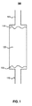
図1は、NO2をNOに変換することによってNOを発生するためのカートリッジ100を示す。NO発生カートリッジ、GENOカートリッジ又はGENOシリンダとも呼ぶことができる該カートリッジ100は、入口105及び出口110を含む。スクリーン及びグラスウール115が、該入口105及び出口110の両方に配置され、該カートリッジ100の残りの部分は、表面活性材料を被覆するために酸化防止剤の飽和水溶液に浸漬した表面活性材料120で充填される。該スクリーン及びグラスウール115もまた、該カートリッジ100に挿入される前に酸化防止剤の飽和水溶液に浸漬される。図1の例において、該酸化防止剤はアスコルビン酸である。
FIG. 1 shows a
NO2をNOに変換する一般的プロセスにおいて、NO2を有する空気流は入口105を介して受け取られ、該空気流は水性酸化防止剤で被覆された表面活性材料120を通って出口110へと流体連通される。表面活性材料が湿潤したままであり、かつ酸化防止剤が該変換で使い果たされていない限り、該一般的プロセスは、周囲温度でのNO2からNOへの変換において有効である。
In the general process of converting NO 2 to NO, an air stream having NO 2 is received via inlet 105, which passes through a surface
図2のシステム200などにおいて、入口105は、液体NO2を含む透過管を超えて空気流を流体連通させた、空気ポンプからのNO2を有する空気流を受け取ることができる。また該入口105は、例えば、NO2タンクとも呼ぶことができるNO2の加圧ボンベからの、NO2を有する空気流を受け取ることもできる。該入口105はまた、窒素(N2)、空気又は酸素(O2)中にNO2を有する空気流を受け取ることもできる。該変換は広い濃度範囲にわたって生じる。約2ppmのNO2から100ppmのNO2、及び1000ppmを超えるNO2に至るまでの空気中の濃度で実験を行った。一実施例において、長さがおよそ15.24cm(6インチ)であり、直径が3.81cm(1.5インチ)のカートリッジに、まずアスコルビン酸の飽和水溶液中に浸漬させたシリカゲルを充填した。該湿潤シリカゲルは、Aldrich Chemical社のA.C.S.(米国化学会)試薬グレード99.1%純度と指定されたアスコルビン酸(すなわちビタミンC)及びS8 32-1、グレード40のサイズ35から70のメッシュと指定されたFischer Scientific International社のシリカゲルを使用して調製した。例えば、0.317cm(1/8インチ)の直径を有するシリカゲルも機能するであろう。
In the
水中35重量%のアスコルビン酸を混合し、攪拌し、及び該水/アスコルビン酸混合物をシリカゲルを通して濾過することによって調製した、アスコルビン酸の飽和溶液を用いてシリカゲルを湿潤させ、続いて脱水した。NO2からNOへの変換は、アスコルビン酸で被覆されたシリカゲルが湿潤しているときに良好に進行することが見出されている。該NO2からNOへの変換は、アスコルビン酸の水性溶液単独ではあまり進行しない。 Silica gel was wetted with a saturated solution of ascorbic acid, prepared by mixing 35% by weight ascorbic acid in water, stirring and filtering the water / ascorbic acid mixture through silica gel, followed by dehydration. It has been found that the conversion of NO 2 to NO proceeds well when the silica gel coated with ascorbic acid is wet. The conversion of NO 2 to NO does not proceed much with an aqueous solution of ascorbic acid alone.
湿潤シリカゲル/アスコルビン酸を充填したカートリッジでは、毎分150mlの流量で、12日間に渡り停止せずに、空気中の1000ppmのNO2をNOに定量的に変換することが可能であった。毎分わずか数mlから毎分5000mlの流量までの範囲の、幅広い流量及びNO2濃度の試験に成功した。また該反応は、ビタミンEの変異体(例えば、αトコフェロール及びγトコフェロール)など、他の一般的な酸化防止剤を使用しても進行する。 With a cartridge filled with wet silica gel / ascorbic acid, it was possible to quantitatively convert 1000 ppm NO 2 in air to NO at a flow rate of 150 ml per minute without stopping for 12 days. A wide range of flow rates and NO 2 concentrations were successfully tested, ranging from just a few ml per minute to a flow rate of 5000 ml per minute. The reaction also proceeds with the use of other common antioxidants such as vitamin E variants (eg, α-tocopherol and γ-tocopherol).
該酸化防止剤/表面活性材料のGENOカートリッジは、吸入治療に使用することができる。そのような一実施例において、該GENOカートリッジは、加圧ボンベ供給源からNOを送達するNO吸入治療用のNO2スクラバーとして使用することができる。該GENOカートリッジを使用して、吸入治療中に化学的に形成される全てのNO2を除去することができる。このGENOカートリッジを使用して、有害レベルのNO2が患者によって不注意に吸入されないように支援することができる。 The antioxidant / surfactant GENO cartridge can be used for inhalation therapy. In one such embodiment, the GENO cartridge can be used as a NO 2 scrubber for NO inhalation therapy that delivers NO from a pressurized cylinder source. Using the GENO cartridge, it is possible to remove all of the NO 2 which is chemically formed during inhalation therapy. This GENO cartridge can be used to help prevent harmful levels of NO 2 from being inadvertently inhaled by the patient.
まず、GENOカートリッジを使用して、従来のNO吸入療法における吸入治療中に使用される安全装置の一部又は全部を補完又は置換することができる。例えば、1つのタイプの安全装置は、NO2の濃度が予め設定された又は所定の制限、通常1ppm以上のNO2を超える場合に、空気中のNO2の存在を警告する。そのような安全装置は、GENOカートリッジが、NOを含んだ空気を吸い込む患者の直前のNO送達システムに配置される場合、不要となり得る。該GENOカートリッジは、患者がNOを含んだ空気を吸い込む直前で全てのNO2をNOに変換し、空気中のNO2の存在を警告する装置を必要なくさせる。 First, GENO cartridges can be used to supplement or replace some or all of the safety devices used during inhalation therapy in conventional NO inhalation therapy. For example, one type of safety device, NO 2 concentrations preset or predetermined limit, if exceeding the normal 1ppm or more NO 2, to warn of the presence of NO 2 in air. Such a safety device may be unnecessary if the GENO cartridge is placed in a NO delivery system just before the patient inhaling air containing NO. The GENO cartridge converts all NO 2 to NO just before the patient inhales NO-containing air, eliminating the need for a device that warns of the presence of NO 2 in the air.
更に、吸入機器及びガス配管(管機構とも呼ぶことができる)の出口付近に配置されたGENOカートリッジは、これらの換気装置内の通過時間により生じるNO2の形成に関連した問題を低減又は排除する。したがって、該GENOカートリッジの使用は、従来の適用において要求される、ガス配管を通るガスの迅速な移動を確実に行う必要性を低減又は排除する。また、GENOカートリッジは、NOガスをガスバルーンとともに使用することを可能にし、患者への総ガス流量を制御する。 In addition, GENO cartridges located near the outlets of inhalation devices and gas pipes (which can also be referred to as pipe mechanisms) reduce or eliminate problems associated with the formation of NO 2 due to the transit time within these ventilators. . Thus, the use of the GENO cartridge reduces or eliminates the need to ensure rapid movement of gas through the gas piping as required in conventional applications. The GENO cartridge also allows NO gas to be used with a gas balloon and controls the total gas flow to the patient.
あるいは又は加えて、患者への送達システム取り付けの直前にNO2除去カートリッジを挿入して、更に安全性を高め、微量の有毒なNO2が全て除去されていることを支援することができる。該NO2除去カートリッジは、いかなる微量なNO2をも除去するために使用されるGENOカートリッジとすることができる。あるいは、該NO2除去カートリッジは、加熱活性化アルミナを含むことができる。Fisher Scientific International社によって供給されるようなA505-212、8〜14のメッシュサイズと指定される加熱活性化アルミナを有するカートリッジは、空気又は酸素の流れから低レベルのNO2を除去するのに有効であり、更にNOガスを損失なく通過させる。活性化アルミナ、及びそれと同様の他の高表面積材料は、NO吸入管からNO2を洗浄するために使用することができる。 Alternatively or additionally, a NO 2 removal cartridge can be inserted just prior to the delivery system being attached to the patient to further increase safety and assist in removing all traces of toxic NO 2 . The NO 2 removal cartridge can be a GENO cartridge used to remove any traces of NO 2 . Alternatively, the NO 2 removal cartridge can include heat activated alumina. A505-212, as supplied by Fisher Scientific International, cartridges with heat activated alumina specified as 8-14 mesh size and effective in removing low levels of NO 2 from air or oxygen streams Furthermore, NO gas is allowed to pass through without loss. Activated alumina, and other high surface area materials similar thereto, can be used to clean NO 2 from the NO inlet tube.
別の実施例において、GENOカートリッジを使用して、治療用ガス送達のためのNOを発生することができる。該NO発生カートリッジは、周囲温度で有害なNO2をNOへと変換するのに有効であるので、液体NO2をNOの供給源として使用することができる。NO発生の供給源として液体NO2が使用される場合、送達システムにNOガスを供給するための加圧ガスボンベは不要である。そのような送達システムの一例を図2についてより詳細に説明する。加圧ガスボンベによるNO提供の必要性を排除することにより、該送達システムは、NOガスの加圧ガスボンベから患者へNOガスを送達するのに使用される従来の装置と比較して、簡易化することができる。加圧ガスボンベを使用しないNO送達システムは、加圧ガスボンベに依拠する従来のシステムよりも可搬性が増され得る。 In another example, a GENO cartridge can be used to generate NO for therapeutic gas delivery. Since the NO generating cartridge is effective in converting harmful NO 2 to NO at ambient temperature, liquid NO 2 can be used as a source of NO. When liquid NO 2 is used as a source for NO generation, a pressurized gas cylinder for supplying NO gas to the delivery system is not required. An example of such a delivery system is described in more detail with respect to FIG. By eliminating the need to provide NO with a pressurized gas cylinder, the delivery system simplifies compared to conventional devices used to deliver NO gas from a pressurized gas cylinder of NO gas to a patient. be able to. NO delivery systems that do not use pressurized gas cylinders may be more portable than conventional systems that rely on pressurized gas cylinders.
図2〜図14は、GENOカートリッジにおいて用いられる表面活性材料として、シリカゲルを使用する技術を示す。先に記載したように、シリカゲルは、NO発生システム又はカートリッジにおいて使用することができる表面活性材料の一例に過ぎない。 2-14 illustrate a technique that uses silica gel as the surface active material used in the GENO cartridge. As described above, silica gel is just one example of a surface active material that can be used in a NO generation system or cartridge.
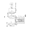
図2は、液体NO2をNO吸入治療用の患者に送達することができるNOガスに変換する、NO発生システム200を示す。一般に、空気ポンプ205によって生み出される空気の流れは、液体NO2及びその二量体N2O4(まとめて236)を有するガス透過セル235を経由して進行する。ガス透過セル235を出た空気流は気体状のNO2を含み、該気体状のNO2は、NO発生カートリッジ240によってNOガスに変換される。NOガス混合物は吸入治療のために、例えば、マスク、カニューレ又はベンチレータを使用して患者へと送達することができる。患者へと送達されるNOガス混合物中のNO濃度は、ガス透過セル235の温度を制御するか、又は流量計220を通る空気流量を制御することによって制御することができる。
FIG. 2 shows a
より具体的には、該システム200は、空気ポンプ205、調整器210、流れ転向装置215及び流量計220を含む。該システムは、空気ポンプ205からの空気流207が、150ml/分の第1の流れ225と、3000ml/分の第2の流れ230とに分流されるように構成される。該空気流207は、乾燥性か又は湿潤性であってもよい。
More specifically, the
該流れ225は、液体NO2及びその二量体N2O4(まとめて236)、並びにガス透過管237を含むガス透過セル235を経由して進行する。該透過セル235はまた、透過発生器、透過装置又は透過管ホルダとも呼ぶことができる。NO2はガス透過セル235のガス多孔質膜を通過して、該流れ225へと拡散する。一実施例において、150ml/分の空気の流れ225は、透過管237、例えば、テキサス州オースティンのKinTek社によって提供された透過管を通過して流れることが可能である。該透過管237が40℃の温度である場合に、該透過管237は、流れ225において透過管を後にするガス流が約840ppmのNO2を含むように、定常的な速度でNO2を放出するように設計される。領域238は、およそ40℃の温度を維持するように温度制御される。下記により詳細に記載するように、該透過セル235の温度を維持することは、患者に送達されるNOの濃度を制御するのに役立つ。
The
次に、840ppmのNO2を含む150mlの空気は、NO発生カートリッジ240を通過して流れる。この実施例において、該NO発生カートリッジ240は、長さ15.24cm(6インチ)、直径3.81cm(1.5インチ)であり、変換試薬として働くシリカゲル上の湿潤アスコルビン酸を含む。該NO発生カートリッジ240は、図1のカートリッジ100の一実施態様であり得る。該NO発生カートリッジ240を出た空気流225は、NO2の全部又は実質的に全部がNOに変換された840ppmのNOを含む。
Next, 150 ml of air containing 840 ppm NO 2 flows through the
次いで、該840ppmのNOを有する150ml/分の流れ225は、3000ml/分の空気又は酸素の流れ230と混合し、40ppmのNOを含む3150ml/分の流れ247が生成される。混合後、該流れ247は、第2のNO発生カートリッジ245を通過して進行し、流れ225と230とが混合されNOが希釈される間に形成され得る全てのNO2を除去する。該NO発生カートリッジ240及び245は、必ずしもそうである必要はないが、同じサイズであってもよい。例えば、該NO発生カートリッジ245は、NO発生カートリッジ240よりも小さいNO2変換能力を有するサイズであってもよい。次いで、得られたNOを有する空気流250は、患者に送達できる状態となっている。該システム200は、数時間の短期間又は14日以上の長期間の間、NOガスの定常的な流れを生成するように設計することができる。一試験において、該システム200は、NO2を含まない、空気中40ppmのNOガスの定常的な流れを12日間に渡って送達することを示した。ここで、該NO及びNO2の濃度は、化学発光ガス分析装置によって測定した。
The 150 ml /
該システム200の代替として、NO発生システムは、透過管237よりも大きな流れ容量を有する透過管を含むことができる。そのような場合、該より大きな透過管は、患者への送達に必要な吸引用空気の全てを処理することができ、例えば、流れ230及び変換管245が不要となる。
As an alternative to the
該システム200は、例えば、空気の供給に使用される空気ポンプ205が、簡易オイルレスポンプなどの可搬式空気ポンプである場合に、可搬式にすることができる。酸素富化空気が患者に必要とされる場合、空気ポンプ205によって供給される空気に加えて、又はその代わりに、酸素を供給することができる。例えば、酸素は酸素タンク又は市販の酸素発生装置から供給することができる。また酸素は、O2と混合されたNO2を有するタンクから供給することもできる。
The
いくつかの実施態様において、透過セル238及び/又は2つの変換カートリッジ240及び245は、使い捨て可能な物品とすることができる。
In some embodiments, the
該システム200を出る流れ250中のNOの濃度は、流れ225が毎分数ミリリットルを上回る限り、透過セル235を通過する流れ225に左右されない。該流れ250中のNOの濃度は、該透過セル235の温度によって変わり、より低い程度で空気流量230によって変わる。例えば、一定の空気流量230で、該システム200は、40℃の温度で40ppmのNOを送達するように設計されるが、該NOの濃度は、30℃で20ppmのNOに低下させることができ、50℃で80ppmに増大させることができる。したがって、温度制御装置を使用して、送達されるNOガスの濃度を調整することができる。所望のNO濃度を選択し、該温度制御装置を、該所望の濃度を送達するための特定温度を維持するように設定すると、所望の濃度のNOガスの送達速度は、一定に維持される。該温度制御装置の一例は、オーブン、例えば、KinTek社から入手可能なオーブンであり、その中に透過管が配置される。温度制御装置の別の例は、ホットプレート上に配置されたビーカー中の脱イオン水のであり、透過管は該ビーカー内に配置される。水温を監視するために、該ビーカー内に温度計を配置してもよい。
The concentration of NO in the
該NO発生システムを使用して、カニューレを用いる使用のために、NOガス混合物の定常的な流れを送達することができ、過剰なガスは環境へと排出される。NO発生システムは、ベンチレータとともに使用することができ、そのような場合、NO発生器からの送達は定常性を維持しなければならず、かつNOを受け取る患者を危険にさらすことなく遮断することはできない。患者の吸気中に流れを増大させる必要性に対処するために、可撓性バッグを膨張させ、次いで収縮させるのにNOガス混合物を使用することができる。患者への空気流が少しでも遅延される場合、NO発生カートリッジをNO発生システムの吸入直前の地点に挿入し、そのような遅延中にNOとO2との反応により形成され得る全てのNO2を除去することができる。これは、該遅延間にバッグ中で形成され得るNO2がどんなに微量であっても、治療用ガス流が患者によって吸引される前に確実に除去されることに役立つ。 The NO generation system can be used to deliver a steady flow of NO gas mixture for use with a cannula, with excess gas being vented to the environment. The NO generation system can be used with a ventilator, in which case delivery from the NO generator must remain stationary and can be blocked without endangering the patient receiving the NO. Can not. To address the need to increase flow during patient inspiration, a NO gas mixture can be used to inflate and then deflate the flexible bag. If any airflow to the patient is delayed, insert a NO generation cartridge at a point just prior to inhalation of the NO generation system, and any NO 2 that can be formed by the reaction of NO and O 2 during such a delay. Can be removed. This helps to ensure that no matter how much NO 2 can be formed in the bag during the delay, the therapeutic gas stream is removed before it is aspirated by the patient.
該治療用ガス送達システム200中に検出器を含み、治療用ガス流内のNO濃度を検出することができる。該検出器はまた、必要に応じて、治療用ガス中のNO2濃度を検出することもでき、NO濃度が所定の範囲外にあるか又はNO2濃度が閾値を超えている場合に、警告を与えることができる。監視技術の例を挙げると、化学発光及び電気化学的技術がある。一酸化窒素の存在は、例えば、化学発光検出器によって検出することができる。
A detector may be included in the therapeutic
図3は、液体NO2をNOガスに変換し、次いで、NO吸入治療のために患者に送達することができる、NO発生システム300を示す。図2のNO発生システム200とは対照的に、該NO発生システム300は、活性アルミナカートリッジ345を含む。該活性アルミナカートリッジ345は、遅延中に形成される全てのNO2を除去する。NO2をNOに変換すること、及びそれによって定量的にNO2の損失を補うことによってNO2を除去するNO発生カートリッジ240とは対照的に、活性アルミナカートリッジ345は、NOを発生することなくプロセスガス流からNO2を除去する。
FIG. 3 shows a
図4に、図1のNO発生カートリッジ100の一実施態様であり得るNO発生カートリッジ440を使用する治療用ガス送達システム400を示す。該システム400は、NO供給源410を使用して、管機構を介して流れ420中の気体状NOを提供する。一実施例において、該NO供給源410は、NOの加圧ボンベとすることができる。管機構を通る空気の流れ430は、空気ポンプ435によって生み出され、流れ420と混合される。該NO発生カートリッジ440へと入る空気流は、気体状NOを含む。流れ420中で形成されたNO2ガスは全て、NO発生カートリッジ440によって除去される。該NO発生カートリッジ440を出た空気流450は、治療用NOガスを含むが、有毒なレベルのNO2は含まない。次いで、該空気流450は、NO吸入治療の患者に送達され得る。
FIG. 4 shows a therapeutic gas delivery system 400 using a
図5に、図1のNO発生カートリッジ100の一実施態様であり得るNO発生カートリッジ540を使用する治療用ガス送達システム500を示す。図4の治療用ガス送達システム400とは対照的に、該システム500は、NO2供給源510からNOを発生する。該NO2供給源510は、NO2供給源510を出た流れ525が気体状NO2を含むように、空気ポンプ520によって生み出された空気流515への液体NO2の拡散を使用することができる。いくつかの実施態様において、該NO2供給源510は、NO2の加圧ボンベとすることができる。
FIG. 5 shows a therapeutic
いずれの場合においても、NO発生カートリッジ440に入る空気流525は、気体状NO2を含む。該NO発生カートリッジ440は、流れ525中のNO2ガスをNOに変換する。該NO発生カートリッジ540を出た空気流550は、治療用NOガスを含むが、NO2を含まないか又は実質的に含まない。次いで、空気流550は、NO吸入治療の患者に送達され得る。
In either case, the
図6に、治療用ガスを送達するための、GENO加圧タンクシステム600を示す。該システム600は、空気中40ppmのNO2を有する市販のタンク620及び流量制御装置622を含む。タンク620の一例では、300立方フィートのタンクが、5L/分の空気流量で1.2日間持続する。
FIG. 6 shows a GENO pressurized tank system 600 for delivering therapeutic gas. The system 600 includes a
空気中NO2の空気流625aは、流量制御装置622を出てGENOカートリッジ640に入る。該GENOカートリッジ640は、前駆物質としてNO2を使用し該NO2をNOに変換する。GENOカートリッジ640を出た空気流625bは、治療用NOガスを含む。該空気流625bは活性アルミナカートリッジ660に入り、該空気流625b中の全てのNO2が除去される。該活性アルミナカートリッジ660を出た空気流625cは、NO吸入治療の患者に送達される。
An air stream 625a of NO 2 in the air exits the
該システム600は、NOxサンプルバルブ665、及びNO2の検出に動作可能なNO-NO2センサ670を含む。NO-NO2センサはまた、NO-NO2検出器と呼ぶこともできる。NOxサンプルバルブ665は、空気流667a及び667bからNO-NO2センサ670に空気サンプルを与えるように動作可能である。該NO-NO2検出器670を使用して空気流667a中のNO2の存在を検出することによって、GENOカートリッジ640の不具合の指標を提供することができ、したがって、有毒なNO2が患者に送達されることがないように細心の安全装置を提供する
The system 600 includes a NO x sample valve 665, and operable NO-NO 2 sensor 670 for detection of NO 2. A NO-NO 2 sensor can also be referred to as a NO-NO 2 detector. The NO x sample valve 665 is operable to provide an air sample from the air streams 667a and 667b to the NO-NO 2 sensor 670. By using the NO-NO 2 detector 670 to detect the presence of NO 2 in the air stream 667a, an indication of a failure of the
いくつかの実施態様において、該活性アルミナカートリッジ660は、GENOカートリッジで置換することができる。
In some embodiments, the activated
いくつかの実施態様において、GENOカートリッジは、ガスボンベからの出力口がGENOカートリッジにのみ接続できるように、特別なネジ筋を有する加圧ガスボンベの出力口に取り付けられる。例えば、該ガスボンベは、約10〜100ppmの濃度のNO2を含む吸気可能な酸素ガスで充填されていてもよい。そのようなシステムは、ガスボンベの圧力を使用して治療用ガスを患者に送達することができ、かつ電子機器又はポンプなどの駆動部を有さなくてもよい。あるいは、該ガスボンベは、NO2を含む空気で充填されていてもよい。加圧ガスボンベ中の空気又は酸素ガスの使用は、混合、及び濃縮NOガスを治療用量まで安全に希釈するのに必要な装置を要する、不活性窒素ガス中のNOを供給する従来の方法を上回る利点を提供する。 In some embodiments, the GENO cartridge is attached to the output port of a pressurized gas cylinder with special threads so that the output port from the gas cylinder can only be connected to the GENO cartridge. For example, the gas cylinder may be filled with inhalable oxygen gas containing NO 2 at a concentration of about 10-100 ppm. Such a system can deliver the therapeutic gas to the patient using the pressure of the gas cylinder and may not have a drive such as an electronic device or pump. Alternatively, the gas cylinder may be filled with air containing NO 2 . The use of air or oxygen gas in a pressurized gas cylinder exceeds conventional methods of supplying NO in inert nitrogen gas, which requires mixing and the equipment necessary to safely dilute the concentrated NO gas to a therapeutic dose. Provides benefits.
図7に、治療用ガスを送達するための、GENO高濃度NO2加圧システム700を示す。図6のシステム600とは対照的に、該システム700は、2つのGENOカートリッジ740及び750、並びに、GENOカートリッジ740又は750のどちらを使用するかを制御するための切換バルブ745を含む。NO-NO2検出器770が、使用中のGENOカートリッジを出た空気流725d中にNO2の存在を検出すると、該切換バルブ745を操作して、空気流725cがもう一方のGENOカートリッジ740又は750を通過するように切り替えることができる。第1のGENOカートリッジが故障した場合に、第2のGENOカートリッジへと切り替えるその能力は、治療用ガスが送達されている患者に更なる安全の階層を提供する。
FIG. 7 shows a GENO high concentration NO 2 pressurization system 700 for delivering therapeutic gas. In contrast to the system 600 of FIG. 6, the
より具体的には、該システム700は、空気中1000ppmのNO2を有するタンク720、及び流量制御装置722を含む。該実施例において、該タンク720は、2250psiにて150立方フィートであるタンクであり、125cc/分の空気流を提供する。患者に送達される40 ppm、5L/分の空気流で、タンク720はおよそ23日間持続する。該タンク720は、GENOカートリッジ740及び750の各々の予想される耐用期間よりも長い期間、空気流を供給することができ、この実施例に使用されるカートリッジにおける該耐用期間は、2週間未満である。したがって、1つのGENOカートリッジから別のGENOカートリッジへと切り替える能力は、確実にタンクの内容物を使用する又は実質的に使用するのに役立つ。
More specifically, the
空気中NO2の空気流725aは、該流量制御装置722を出て、空気ポンプなどの空気供給源730によって生み出された5L/分の空気流725bと混合される。得られた空気流725cは、切換バルブ745に入る。該切換バルブ745は、GENOカートリッジ740又は750のどちらが該空気流725cを受け取るかを制御する。示されるように、該切換バルブ745は、該空気流725cがGENOカートリッジ750に供給されるように設定される。該GENOカートリッジ750は、空気流725c中のNO2をNOに変換する。該GENOカートリッジ725dを出た空気流725dは、治療用NOガスを含む。空気流725dは活性アルミナカートリッジ760に入り、該空気流725d中の全てのNO2が除去される。該活性アルミナカートリッジ760を出た空気流725eは、NO吸入治療の患者に送達される。
The
該システム700は、NOxサンプルバルブ765、及びNO2を検出するように動作可能なNO-NO2センサ770を含む。該NOxサンプルバルブ765は、空気流767a及び767bからの空気サンプルを、NO-NO2センサ770へ提供するように動作可能である。NO-NO2センサ770を使用して、該空気流767a中のNO2の存在を検出することは、第2のGENOカートリッジを使用することができるように、使用中のGENOカートリッジの故障の指標を提供することができる。いくつかの実施態様において、該活性アルミナカートリッジ760は、GENOカートリッジで置換することができる。
The
図8に、治療用ガスを送達するための、GENO高濃度NO2カートリッジシステム800を示す。図6及び図7のそれぞれのシステム600又は700とは対照的に、該システム800は、NOの発生に使用されるNO2の供給源として、高濃度NO2カートリッジを含む。より詳細には、該システム800は、NO2カートリッジ800、例えば、小型のブタンタンク又はCO2を送達するのに従来使用されるカートリッジなどを含む。該システム800の一実施例において、2.54cm(1インチ)×15.24cm(6インチ)の寸法を有し、CO2中の5%のNO2で充填されたNO2カートリッジは、14日間NO2を送達することが可能であった。
FIG. 8 shows a GENO high concentration NO 2 cartridge system 800 for delivering therapeutic gas. In contrast to the
NO2遮断バルブ821は、カートリッジ800に隣接して、該カートリッジ800からのNO2の送達を遮断する。またシステム800は流量制御装置822を含み、ほぼ一定流量の流れ825aが該流量制御装置822から出るようにする。該流量制御装置822は、ガス流825aがそこを通過する小さい穴を有するガラス管である。システム800の様々な実施態様において、該流量制御装置822は、1〜10cc/分の一定流量を確実にすることができる。
The NO 2 blocking valve 821 blocks the delivery of NO 2 from the
NO2を有するガス流825aは、流量制御装置822を出て、空気供給源830によって生み出されたおよそ5L/分の空気流825bと混合される。ガスミキサ835は、空気流825a及び825bが十分に(又は実質的に十分に)混合されることを確実にする。得られたNO2を有する空気流825cは、NOを発生するGENOカートリッジ840に入る。
The gas stream 825a with NO 2 exits the
また該システム800は、活性アルミナカートリッジ860を含み、NOを含む治療用ガスが約5L/分の速度で患者に送達される前に、全てのNO2が取り除かれる。
該システム800は、NOxサンプルバルブ865、及びNO2を検出するように動作可能なNO-NO2センサ870を含む。いくつかの実施態様において、活性アルミナカートリッジ860を、GENOカートリッジで置換することができる。
The
The
図9に、治療ガスを送達するためのGENO透過システム900を示す。該システム900は、GENOカートリッジ940に流れるおよそ5L/分の空気流925aを含み、該カートリッジは空気を加湿するように作用する。該GENOカートリッジ940を出た後、空気流925aは、空気流925bが透過装置935を通過し、かつ空気流925cが通過しないように分離する。該透過装置935は、透過管機構937、及び空気流925aの開始時に約10ccの液体NO2936を含む。該透過装置935は、図2の透過セル235の一実施態様であり得る。該透過装置935は、透過オーブン939内に位置し、所望の濃度のNO2が空気流925bに拡散することを確実にするために、一定の又は実質的に一定の温度を維持する。空気流925b及び空気流925cは、GENOカートリッジ950に入る前に、混合して流れ925dを形成する。該GENOカートリッジ950はNO2をNOに変換する。
FIG. 9 shows a
該システム900はまた、活性アルミナカートリッジ960を含み、該カートリッジは、空気流925eを受け取り、NOを含む治療用ガスがおよそ5L/分の流速で患者に送達される前に全てのNO2を除去する。該活性アルミナカートリッジを出た空気流925fは、NO吸入治療の患者に送達される。該システム900は、NOxサンプルバルブ965、及びNO2を検出するように動作可能なNO-NO2センサ970を含む。
The
図10に、治療用ガスを送達するためのGENO透過システム1000を示す。図9のシステム900とは対照的に、該システム1000は、GENOカートリッジ1040及び1050のどちらが最初に空気流を受け取るかを制御するためのバルブ1010及び1015を含む。該システム1000は、NOに変換されるNO2供給源として、透過装置1035中の液体NO2を使用する。該システム1000はまた、活性化アルミナカートリッジ1060を含み、NOを含む治療用ガスがおよそ5L/分の流量で患者に送達される前に、全てのNO2を除去する。また該システム1000は、NOxサンプルバルブ1065、及びNO2を検出するように動作可能なNO-NO2センサ1070を含む。
FIG. 10 shows a
該システム1000は、バルブ1010へのおよそ5 L/分の空気流1025aを受け取り、該バルブ1010は、バルブ1015とともに、該空気流1025aがGENOカートリッジ1040又は1050のどちらを最初に通過するかを制御する。より具体的には、該バルブ1010及び1015の位置を制御することによって、該空気流1025aは、GENOカートリッジ1040、透過装置1025、GENOカートリッジ1050、次いで、活性化アルミナカートリッジ1060を通過させることができ、その後、患者に送達される。該バルブ1010及び1015の位置を操作することによって、該空気流1025aをまた、GENOカートリッジ1050、透過装置1025、GENOカートリッジ1040、次いで、活性化アルミナカートリッジ1060を通過させることができ、その後、患者に送達される。
The
例えば、NO-NO2センサ1070が空気流1025b中にNO2の存在を検出すると、該センサは、バルブ1010及び1015を操作する必要性の信号を送り、GENOカートリッジ1040及び1050を切り替えて使用するという命令を与える。すなわち、例えば、該空気流1025aがGENOカートリッジ1040を通過し、その後、後続のGENOカートリッジ1050を通って流れている場合、該バルブ1010及び1015を操作して、該空気流1025aがGENOカートリッジ1050を通過し、その後、後続のGENOカートリッジ1040を通って流れるようにさせる。
For example, if the NO-NO 2 sensor 1070 detects the presence of NO 2 in the air stream 1025b, it sends a signal indicating the need to operate the
いくつかの市販の適用において、NO2は酸素又は空気中およそ10〜100ppmの所定の濃度で販売され得る。 In some commercial applications, NO 2 may be sold at a given concentration of approximately 10~100ppm oxygen or air.
図11は、NO2をNOに変換する、GENOカートリッジ1100の概念的デザインを示す。該GENOカートリッジ1100は、図1のカートリッジ100の一実施態様であり得る。該GENOカートリッジ1100は、長さおよそ15.24cm(6インチ)、直径2.54cm(1インチ)である。該GENOカートリッジ1100は、アスコルビン酸の水性溶液で飽和されたシリカゲルを含み、NO2を含む空気又は酸素ガスボンベから空気流を受け取る。カートリッジ1100を通る空気流は、NO2をNOに変換され、カートリッジ1100を出る。該GENOカートリッジ1100は、5ppmから5000ppmのNO2濃度で有効に機能する。該GENOカートリッジ1100を用いるNO2からNOへの変換は、熱源を必要とせず、かつ周囲空気温度で使用することができる。該GENOカートリッジ1100を用いたNO2からNOへの変換は、該GENOカートリッジ1100を通過する空気流の流量とは実質的に無関係に起こる。
FIG. 11 shows a conceptual design of a
図12に、NO2を含むガスボンベ1220及びGENOカートリッジ1210を含む治療用ガス送達システム1200を示す。該GENOカートリッジ1210は、ガスボンベ1220からのNO2をNO吸入治療の患者に送達するNOへ変換するための、図11のGENOカートリッジ1100の一実施態様であり得る。該システム1200は、可搬式となるように設計される。いくつかの実施態様において、該システム1200は、電子機器又はセンサを使用することなく動作するよう設計することができる。ガスボンベ1220の容量に応じて、一般に該システム1200は、治療用NOガスを1から16時間送達する能力を有する。
FIG. 12 shows a therapeutic
システム1200は、緊急体制における患者への治療用NOガスの送達に用いることができる。そのような状況の例を挙げると、緊急医療隊員、衛生兵又は野戦病院、消防士、救急隊員、及び病院の救急治療室又は外傷センターによる使用がある。別の例として、可搬式治療用NOガス送達装置は、酸素富化空気で呼吸している困窮した登山者を援助するのに使用することができる。更に別の例において、可搬式治療用NOガス送達装置は、主要NO供給源が故障している患者に使用することができる。いくつかの実施態様において、可搬式治療用NOガス送達装置は、一度限りの使用として設計することができる。
図13Aに、液体NO2供給源を有する治療用ガス送達システムの外観1300Aを示す。図13Bは、図13Aに示した治療用ガス送達システムの内部図1300Bを示す。該治療用ガス送達システムは、液体NO2供給源を有する透過管1310を含み、該透過管1310は、例えば、図9の透過装置935の一実施態様であり得る。該治療用ガス送達システムはまた、GENOカートリッジ1340及び1350を含む。該GENOカートリッジ1340は、空気又は酸素供給源からの空気流1325aを受け取る。該GENOカートリッジ1340を出た後、空気流は、およそ10%の空気流が透過管1310を通過して流れ、これにより気体状NO2が該空気流中に拡散するように分離される。該透過管1310を出た空気流、及び該透過管1310を通らなかったその他の空気流は、NO2をNOに変換するGENOカートリッジ1350を通過して流れる。該GENOカートリッジ1350を出た空気流1325b及び1325cは、NO吸入治療の患者に送達される。該透過管1310、並びにGENOカートリッジ1340及び1350は、使い捨てとすることができる。
FIG. 13A shows an
該透過管1310の容量に応じて、図13A及び図13Bに示した治療用ガス送達システムは、1〜30日間の治療用NOガス送達能力を有し得る。
Depending on the capacity of the
図13A及び図13Bに示した治療用ガス送達システムは、ベンチレータと連動することができる。また該図13A及び図13Bに示した治療用ガス送達システムを用いて、カニューレを使用した患者への治療用NOガス送達を行うことができる。例えば、毎分2リッターの流量で、該治療用NOガスの送達をカニューレを通して提供することができる。カニューレを用いる治療用ガス送達システムの使用により、NO治療を病院環境外で行うことを可能にする。そのような例の1つは、患者の自宅で行われる長期のNO治療のための治療用ガス送達システムの使用である。 The therapeutic gas delivery system shown in FIGS. 13A and 13B can work with a ventilator. The therapeutic gas delivery system shown in FIGS. 13A and 13B can be used to deliver therapeutic NO gas to a patient using a cannula. For example, delivery of the therapeutic NO gas can be provided through a cannula at a flow rate of 2 liters per minute. The use of a therapeutic gas delivery system with a cannula allows NO treatment to be performed outside the hospital environment. One such example is the use of a therapeutic gas delivery system for long-term NO treatment performed at the patient's home.
図13Cに、炭酸飲料の缶1350と比較した、図13A及び図13Bに示した治療用ガス送達システムの外観1300Aを示す。図示のように、図13A〜図13Cに示した治療用ガス送達システムの実施態様は、従来のNO吸入治療システムに比べて小型の装置であり、炭酸飲料の缶よりもわずかに大きい。 FIG. 13C shows the exterior 1300A of the therapeutic gas delivery system shown in FIGS. 13A and 13B compared to a carbonated beverage can 1350. FIG. As shown, the therapeutic gas delivery system embodiment shown in FIGS. 13A-13C is a small device compared to a conventional NO inhalation therapy system and slightly larger than a carbonated beverage can.
図14に、GENOカートリッジを使用してNO2をNO吸入治療で使用するためのNOに変換する、治療用ガス送達システム1400の外観を示す。該システム1400は、GENOカートリッジを挿入又は接続できるGENOカートリッジポート1410及び1415を含む。該システム1400は、空気又は酸素がそれを通ってシステム1400へ流入する入口ポート1420及び付属の計器1425を含む。該システム1400は、空気流を制御するための、フロー値1430及び表示器1435を含む。該システム1400は、GENOカートリッジフローポート1440を含む。
FIG. 14 shows the appearance of a therapeutic
また該システム1400は、温度制御装置1445、及びNOx検出器アクセス1455によりアクセス可能なNOx検出器1450を含む。該システム1400はまた、GENOカートリッジ1460を含み、該カートリッジ1460は、基本的にNOを有する空気流が出口1465を通りシステム1400を出る直前で、NO2をNOに変換するために使用される。該GENOカートリッジ1460は、安全スクラバーと呼ぶこともできる。該GENOカートリッジ1460は、該システム1400の他の部分で使用されるGENOカートリッジよりも小さくてもよい。また該システム1400は、バックアップ入力ポート1470及び排気ファン1475を含む。
Also the
(更なる例示的実施態様) (Further exemplary embodiments)
これら更なる例示的実施態様は、酸素又は空気又はいくつかの組合せ中にNO2として貯蔵された、必要用量のNOを含むガスボンベを使用する。ガスは該ガスボンベからの放出において、下記のように変換される。
正 2NO2→2NO+O2
These further exemplary embodiments use gas cylinders containing the required dose of NO stored as NO 2 in oxygen or air or some combination. The gas is converted as follows in the release from the gas cylinder.
Positive 2NO 2 → 2NO + O 2
この反応は、GENOカートリッジにおいて、湿潤シリカゲルマトリックスのアルコルビン酸上にて1秒未満で起こる。システムの圧力は、ガスが該システムを通過するのに必要な力を維持しなければならない。通常、該力は約0.01〜50psiである。NOが形成されるとすぐに、下記の逆反応が起こる。
逆 NO+NO+O2→2NO2
This reaction occurs in less than 1 second on the ascorbic acid of a wet silica gel matrix in a GENO cartridge. The system pressure must maintain the force necessary for the gas to pass through the system. Usually, the force is about 0.01-50 psi. As soon as NO is formed, the following reverse reaction occurs:
Reverse NO + NO + O 2 → 2NO 2
圧力が高いほど、より速くこの反応が起こる;実際、その速度は圧力について3次である。調整器の高圧側でのNO2からNOへの変換は、逆反応が正反応とほぼ同じ速さで起こっている場合には起こらない。この問題に対処するために、圧力調整器の低圧側にGENOカートリッジを設置することによって該逆反応を最小化する。これを下記図16に示す。ガスはガスボンベを出て、調整器を通過し、次いで、第1のカートリッジを下り接続管まで流れ、次に、第2のカートリッジに流れ、次いで、外へ出て使用者へと流れる。 The higher the pressure, the faster this reaction takes place; in fact, the rate is third order with respect to pressure. The conversion of NO 2 to NO on the high pressure side of the regulator does not occur when the reverse reaction occurs at about the same rate as the forward reaction. To address this problem, the reverse reaction is minimized by installing a GENO cartridge on the low pressure side of the pressure regulator. This is shown in FIG. The gas exits the gas cylinder, passes through the regulator, then flows through the first cartridge to the downcomer tube, then into the second cartridge, and then exits to the user.
2つのカートリッジを、順々に、直列で使用する。その理由は、2重のリダンダンシーを与えることにある。1つのカートリッジで十分に機能するが、第2のカートリッジを有することでリダンダンシーを与える。各カートリッジは、100ppmで40%の余剰容量から20ppmに対して20×の余剰容量までのガスボンベの全内容物を捕捉するように大きさが設定されている。したがって、この例示的実施態様は、2つの同一のカートリッジを使用し、1つのカートリッジだけを使用する時の2倍のバックアップを提供する。 Two cartridges are used in series, one after the other. The reason is to give double redundancy. One cartridge works well, but having a second cartridge provides redundancy. Each cartridge is sized to capture the entire contents of the gas cylinder from 40% surplus capacity at 100 ppm to 20 × surplus capacity for 20 ppm. Thus, this exemplary embodiment uses two identical cartridges and provides twice the backup when using only one cartridge.
(操作と安全性) (Operation and safety)
システムの使用の安全性を向上させる別の方法は、ガスボンベのカバーの一体部分としてカートリッジを収めることである。これを調整器とともに下記図17に示す。そのような実施態様において、使用者はガスボンベを受け取り、次いで、特殊な調整器をガスボンベに取り付ける。特別に固定されたCGA継手を使用することで、GENO調整器だけが使用され得る。しかし、該調整器の出力口は、ガスボンベのカバーに取り付けられたGENOカートリッジへの導入口になるように形成されてもよい。このように、使用者が該ボンベから排出されるガスを得ることができる唯一の方法は、特別なCGA継手を有する調整器を使用することであり、かつ該調整器から出てくるガスを得る唯一の方法は、GENOカートリッジに接続することである。このように、ガスボンベから出ているガスだけが、GENOカートリッジを通過することができる。 Another way to increase the safety of use of the system is to house the cartridge as an integral part of the cover of the gas cylinder. This is shown in FIG. In such an embodiment, the user receives the gas cylinder and then attaches a special regulator to the gas cylinder. By using specially fixed CGA fittings, only GENO regulators can be used. However, the output port of the regulator may be formed to be an inlet port to a GENO cartridge attached to the cover of the gas cylinder. Thus, the only way a user can get the gas exhausted from the cylinder is to use a regulator with a special CGA fitting and get the gas coming out of the regulator The only way is to connect to the GENO cartridge. In this way, only gas exiting from the gas cylinder can pass through the GENO cartridge.
これを図18に示す。カートリッジは、常にガスボンベとともにある。例えば、ボンベを補充するために返却する場合でさえも、使用したカートリッジは、該ガスボンベに残されたままである。ガス充填に次いで、使用済みカートリッジを取外し、該使用済みカートリッジと新しいカートリッジとを取り替える。 This is shown in FIG. The cartridge is always with the gas cylinder. For example, used cartridges remain in the gas cylinder even when returned to refill the cylinder. Following gas filling, the used cartridge is removed, and the used cartridge is replaced with a new cartridge.
図18に、ガスボンベの出口及びカートリッジの入口に接続された調整器を示す。更なる安全性のために、該カートリッジからの出力は、酸素ガス中のNOが特別な補助器具を用いてのみ使用できるように、同様に鍵をかけることができる。 FIG. 18 shows the regulator connected to the outlet of the gas cylinder and the inlet of the cartridge. For added safety, the output from the cartridge can be similarly locked so that NO in oxygen gas can only be used with special aids.
NOガスの濃度を変更するためには、異なるガスボンベを使用する。ガスボンベ中のNOガス濃度の特定に有用な1つの方法は、各濃度のボンベに異なる色をもたせることである。例えば、20ppmの濃度を有するボンベを青とし、対して100ppmの濃度を有するボンベを赤とする。各濃度は、それ自身の特別な鍵のついたガスボンベを有することができ、それはまた、使用する目的の濃度と異なったNOガス濃度を、意図せず使用することを減少させる、又はそれを防止するのに役立ち得る。ガスボンベの取り違えを防止するために、例えば、100ppmの濃度を有するボンベはある場所でボンベに充填されるのに対し、20ppmの濃度のボンベは異なった場所でボンベに充填されるなど、異なる濃度を異なる場所でボンベに充填してもよい。 Use different gas cylinders to change the concentration of NO gas. One useful method for determining the NO gas concentration in a gas cylinder is to have a different color for each concentration cylinder. For example, a cylinder having a concentration of 20 ppm is blue, whereas a cylinder having a concentration of 100 ppm is red. Each concentration can have its own special key gas cylinder, which also reduces or prevents unintentional use of NO gas concentrations that differ from the intended concentration used. Can help to. To prevent gas cylinders from being mixed up, for example, a cylinder with a concentration of 100 ppm is filled in a cylinder at one location, while a cylinder with a concentration of 20 ppm is filled in a cylinder at a different location. The cylinders may be filled at different locations.
いくつかの実施態様において、カートリッジの構造は3部分のみを含み得る。第1の部分は、図19に示すように、2つの管の間に第3の導管を有する対をなす管である。 In some embodiments, the cartridge structure may include only three parts. The first part is a pair of tubes having a third conduit between the two tubes, as shown in FIG.
図20にも、2つの管の間に第3の導管を有する対をなす管を示す。 FIG. 20 also shows a pair of tubes with a third conduit between the two tubes.
この3部分のカートリッジの構造のエンドキャップを、図21A及び21Bに示す。 The end cap of this three-part cartridge structure is shown in FIGS. 21A and 21B.
該キャップの内部は、中心管が形作られている。該管とキャップと管との密閉は、超音波溶着によって達成され得る。該管の密閉は、溶剤接着、O-リング又は締め具による密閉などの別の技術を使用して達成することができる。該キャップの特徴は、キャップ表面に迅速脱着用のオス部が成形されていることであり;それによって、カートリッジ全体を使い捨て部材とさせる。 A central tube is formed inside the cap. Sealing of the tube, cap and tube can be accomplished by ultrasonic welding. Sealing the tube can be accomplished using other techniques such as solvent bonding, sealing with O-rings or fasteners. The cap is characterized by a male part for quick removal on the cap surface; thereby making the entire cartridge a disposable member.
カートリッジは下記のように組み立てることができる。
1. 粉体を保持するような細孔サイズを有するプラスチック製のフリットを、エンドキャップに挿入する。
2. 管と1つのエンドキャップを互いに溶接し、該フリットがカートリッジから出る粉体を防ぐフィルタとして動作する位置にあるようにする。
3. 該管に試薬粉を充填する。充填の間、該粉末を圧縮し、振動させて、均一で隙間のない封入、及び全ての空所の除去を確実に行うようにする。該管が充填されると、所定の位置にフィルタを有する第2のエンドキャップを管の上部に設置し、所定の位置に接合する。
4. 必要であれば、該システムを窒素ガスで洗浄して、該システムから酸素を除去する。
5. 水分の混入を阻止するために、プラスチック製のエンドキャップを入口及び出口管上に設置する。
The cartridge can be assembled as follows.
1. Insert a plastic frit with a pore size to hold the powder into the end cap.
2. Weld the tube and one end cap together so that the frit is in a position to act as a filter to prevent powder from exiting the cartridge.
3. Fill the tube with reagent powder. During filling, the powder is compressed and vibrated to ensure uniform and tight encapsulation and removal of all voids. When the tube is filled, a second end cap having a filter at a predetermined position is placed on the upper part of the tube and joined to the predetermined position.
4. If necessary, flush the system with nitrogen gas to remove oxygen from the system.
5. Place plastic end caps on the inlet and outlet pipes to prevent moisture contamination.
(レキュペレータカートリッジ) (Recuperator cartridge)
レキュペレータカートリッジは、吸入直前のガス配管に挿入される。該レキュペレータの目的は、ベンチレータにおいて、及びガスバッグ又は他の一時的なガス保管装置に保管する間に形成された全てのNO2ガスをNOに変換し戻すことである。図22A及び22Bに、レキュペレータの他の実施態様を示す。 The recuperator cartridge is inserted into the gas pipe just before inhalation. The purpose of the recuperator is to convert all NO 2 gas formed in the ventilator and during storage in a gas bag or other temporary gas storage device back to NO. 22A and 22B show another embodiment of the recuperator.
あるいは、該レキュペレータは、第1のカートリッジの1つと同じ大きさ及び形態であってよい。これは、操作におけるシステムの安全性を更に増大させる。例えば、ガスボンベの全内容物をNO2からNOへ変換することができるレキュペレータを用いることによって、該レキュペレータは該システムに3重のリダンダンシーを与える。 Alternatively, the recuperator may be the same size and form as one of the first cartridges. This further increases the safety of the system in operation. For example, by using a recuperator that can convert the entire contents of a gas cylinder from NO 2 to NO, the recuperator provides triple redundancy to the system.
(他の用途) (Other uses)
該ガスボンベは、NOを伴う他の用途にも使用することができる。該ガスボンベを使用して、電子機器の使用なしに、充填されたガスを送達することができる。該システムの利点を挙げると、簡便、混合不要、電子機器不要及びソフトウェア不要がある。操作のために、調節器を接続しバルブを開く。 The gas cylinder can also be used for other applications involving NO. The gas cylinder can be used to deliver a filled gas without the use of electronic equipment. The advantages of the system are simple, no mixing, no electronic equipment and no software. Connect the regulator and open the valve for operation.
また該GENOガスボンベシステムは、希釈器とともに使用することができる。実施態様の例において、例えば、ガスは酸素中1000ppmのNO2として輸送される。第1段階で、使用者の装置は、この濃度から、例えば20ppmのNO2に希釈する。第2段階は、GENOカートリッジを挿入し、該ガスをNOに変換する。NO2はレキュペレータによってNOに変換されることになるから、該レキュペレータカートリッジは、使用者が懸念するガスライン中で形成される全てのNO2について、低下させるのに役立つ。同様に、該レキュペレータカートリッジを現行のシステムとともに使用して、吸引時に、残留しているNO2ガスの全てを医療用形態、つまりNOに変換することができる。また、該レキュペレータは、該システムからNOガスが失われることなく、かつ患者が十分な所定用量を受けられるようにする。 The GENO gas cylinder system can be used with a diluter. In an example embodiment, for example, the gas is transported as 1000 ppm NO 2 in oxygen. In the first stage, the device of the user, be diluted from this concentration, for example, 20ppm of NO 2. The second stage inserts a GENO cartridge and converts the gas to NO. Since NO 2 will be converted to NO by the recuperator, the recuperator cartridge helps to reduce all NO 2 formed in the gas line that the user is concerned about. Similarly, the recuperator cartridge can be used with current systems to convert all of the remaining NO 2 gas into a medical form, ie NO, upon aspiration. The recuperator also allows the patient to receive a sufficient predetermined dose without losing NO gas from the system.
GENOは、NO2という毒性形態の存在なしに、100〜200ppmの範囲又は更に高い、高用量のNOを送達できるという事実が重要であろう。これは、達成し得る用量を制限する有毒なNO2の存在のために、送達用量がおよそ20ppmの範囲に制限されているという難点に対処する。該GENOシステムは、吸引ガスにおけるNO2毒性の問題を排除する。このことは、多数の疾患、特にARDS(「急性呼吸促迫症候群」)の治療に対するNOガスの有用性を増大させるか、あるいは更に大きく増大させ得る。 The fact that GENO can deliver high doses of NO, in the range of 100-200 ppm or even higher, without the presence of a toxic form of NO 2 would be important. This addresses the difficulty that the delivery dose is limited to the range of approximately 20 ppm due to the presence of toxic NO 2 which limits the dose that can be achieved. The GENO system eliminates the problem of NO 2 toxicity in the aspirated gas. This can increase or even increase the usefulness of NO gas for the treatment of a number of diseases, particularly ARDS (“Acute Respiratory Distress Syndrome”).
(GENO カートリッジ) (GENO cartridge)
(NO2/O2ガスボンベの安全性) (Safety of NO 2 / O 2 gas cylinder)
GeNO技術のいくつかの実施態様において、NO2を酸素又は空気のいずれかに約20ppmで分配し、かつGeNOカートリッジをガスボンベの高圧側に設置する。該カートリッジは、タンクの全NO2(毒性である)内容物を、無毒性であるNOガスに変換する能力を有する(図23参照)。この高圧カートリッジは、タンクとともに送達することができ、かつ特別に設計された継手のために、タンク製造者によってのみ取り外されるように設計されている。また、このカートリッジは、次に通常の医療用の使用のための接続を有するGeNOカートリッジ(低圧)の取り付けが可能な、調整器のための継手を有してもよい。これは、低圧カートリッジの使用なしにタンクを使用することを防止するのに役立ち、該低圧カートリッジは、タンク中のNO2の全内容物を変換する能力も有する予備の安全カートリッジである。またこれは、何者かが酸素又は空気中の毒性NO2ガスを含むガスボンベに、GeNOではない調整器を取り付ける可能性を低減させるのみならず、調整器欠如時に、部屋内へのタンク内容物の偶発的な放出の可能性を低減させるのに役立つ。 In some embodiments of GeNO technology, NO 2 is dispensed into either oxygen or air at about 20 ppm and a GeNO cartridge is installed on the high pressure side of the gas cylinder. The cartridge has the ability to convert the entire NO 2 (toxic) content of the tank to non-toxic NO gas (see FIG. 23). This high pressure cartridge can be delivered with the tank and is designed to be removed only by the tank manufacturer for a specially designed fitting. The cartridge may also have a fitting for the regulator, which can then be fitted with a GeNO cartridge (low pressure) with connections for normal medical use. This helps to prevent the use of the tank without the use of a low pressure cartridge, which is a spare safety cartridge that also has the ability to convert the entire contents of NO 2 in the tank. This not only reduces the possibility of someone installing a regulator that is not GeNO into a gas cylinder that contains oxygen or toxic NO 2 gas in the air, but also in the absence of a regulator, Helps reduce the possibility of accidental release.
(主要装置故障時の支援システム) (Support system for major equipment failure)
更に又はあるいは、第2の、重複した装置(タンク、調整器及びカートリッジを含む)を利用して、患者の投与源を別のタンクへ迅速に切り替えることを可能にする。 Additionally or alternatively, a second, redundant device (including tanks, regulators and cartridges) can be utilized to quickly switch the patient's administration source to another tank.
(透過管) (Transmission tube)
(拡散セルの使用) (Use of diffusion cell)
拡散セルは、透過管の壊滅的な破裂と関連する危険を最小化するか、又は軽減さえするのに役立つことができる。毎分5リッターの空気中20ppmのNOという常用量は、1日あたり約0.33gのNO2となる。10日の供給では、3〜4gの液体NO1/N2O4を有し得る。透過管が突然破裂した場合、内容物が部屋内に漏れ出し、特許(patent)及びスタッフのいずれにとっても深刻な危険を生み出す。この安全性の問題を緩和するために、液体NO2をステンレス鋼又は強化プラスチック製の強固な拡散セルに貯蔵することができる。該拡散セルは狭口径の皮下針によって透過管に接続され、該透過管のためのリザーバとして作用する。透過管の壊滅的な破損時に、該液体は狭口径針を通って数時間から数日にわたりゆっくりと流れ出し、それによって、毒性のNO2の最悪かつ突然の放出を回避する。更に、該拡散セルは、例えば、押しつぶし、コンクリートへの落下、又は鋭利な物体による損傷に十分耐えるほど強固に作製することができる。 The diffusion cell can help to minimize or even mitigate the risks associated with catastrophic rupture of the permeation tube. A normal dose of 20 ppm NO in 5 liters of air per minute results in approximately 0.33 g NO 2 per day. A 10 day supply can have 3-4 g of liquid NO 1 / N 2 O 4 . If the permeation tube bursts suddenly, the contents leak into the room, creating serious danger for both patents and staff. To alleviate this safety issue, liquid NO 2 can be stored in a strong diffusion cell made of stainless steel or reinforced plastic. The diffusion cell is connected to the permeation tube by a narrow bore hypodermic needle and acts as a reservoir for the permeation tube. During catastrophic failure of the transmission tube, it flows slowly over hours or days liquid passes through the narrow bore needles, thereby avoiding the worst and sudden release of toxic NO 2. Furthermore, the diffusion cell can be made strong enough to withstand, for example, crushing, dropping onto concrete, or damage from sharp objects.
(2重のリダンダンシー) (Double redundancy)
いくつかの実施態様において、該拡散セルは、透過管によって、必要とされるよりわずかに多いNO2を送達するように設計されている。したがって、長さ10.16cm(4インチ)、内径0.051mm(0.002インチ)の中空管を有するステンレス鋼製のセルは、35℃にて毎分5リッターの空気中20ppmよりわずかに多くのNO2を供給するのに十分な素材を提供する。該セルからの拡散速度は、毎分約200,000ngとすべきである。この方法を使用する場合、該拡散セルは、安全装置としてだけでなく、透過管にとっての放出機構のバックアップ制御としても作用する。透過管の壊滅的かつ突然の故障が発生した時でさえ、該拡散セルは適切な用量を供給し続ける。したがって、該拡散管は透過管のための貯蔵装置として使用され、かつ該透過管及び該拡散セルは互いに動作し、安全性のための2重のリダンダンシーを与えている(図24を参照)。 In some embodiments, the diffusion cell is designed to deliver slightly more NO 2 than required by the permeation tube. Therefore, a stainless steel cell with a hollow tube of 10.16 cm (4 inches) long and 0.051 mm (0.002 inches) ID is slightly more than 20 ppm NO 2 in air at 35 ° C. and 5 liters per minute. Provide enough material to supply. The diffusion rate from the cell should be about 200,000 ng per minute. When using this method, the diffusion cell acts not only as a safety device, but also as a backup control of the discharge mechanism for the permeation tube. Even when a catastrophic and sudden failure of the permeation tube occurs, the diffusion cell continues to provide the proper dose. Thus, the diffusion tube is used as a storage device for the permeation tube, and the permeation tube and the diffusion cell work together to provide double redundancy for safety (see FIG. 24).
(透過と拡散に対する温度の影響) (Effect of temperature on permeation and diffusion)
透過管及び/又は拡散セルからのNO2の透過速度及び/又は拡散速度は、温度に依存する。NO2の場合、温度が10℃増加するごとに、速度は約1.9倍増加する。透過管及び拡散セルの典型的な使用において、この速度増加は温度を制御することによって制御される。GENOの用途においては、温度を制御せずに、およそ15〜35℃の温度範囲でガスを供給することが望ましい。これは、例えば、下記の概念及び技術を使用して達成し得る。 The permeation rate and / or diffusion rate of NO 2 from the permeation tube and / or diffusion cell depends on the temperature. In the case of NO 2 , the rate increases about 1.9 times for every 10 ° C increase in temperature. In typical use of permeation tubes and diffusion cells, this rate increase is controlled by controlling the temperature. In GENO applications, it is desirable to supply gas in a temperature range of approximately 15 to 35 ° C. without controlling the temperature. This can be accomplished, for example, using the following concepts and techniques.
(透過管)
透過管において、透過できる物質の量は、管の長さに正比例する。したがって、より長い管は、短い管よりもよりNO2を送達できる。これを考慮し、可動性で、滑動する、非透過性の覆いを使用して、曝される透過管の量を調整し、既知温度におけるNO2の送達を調節することができる(図25参照)。該管の長さは、最も低い設定温度で、適切な用量を供給するように定められる。この例において、該管は、15℃でおよそ200,000ng/分で送達するように設計されている。管上を滑動させ、該管の約3/4の長さを覆うスリーブが提供される。したがって、15℃では、管全体がさらされる。温度が25℃のとき、該管からの拡散速度は2倍であり、該管の活性長をの1/2を覆うことにより、これを補正する。35℃では、毎分およそ200,000ngの同一の透過速度を維持するのに、該管の1/4だけが必要となる。
(Transmission tube)
In a permeation tube, the amount of material that can permeate is directly proportional to the length of the tube. Therefore, the longer the tube, capable of delivering more NO 2 than short tube. With this in mind, a movable, sliding, non-permeable covering can be used to adjust the amount of permeation tube exposed and to regulate the delivery of NO 2 at known temperatures (see FIG. 25). ). The length of the tube is determined to deliver an appropriate dose at the lowest set temperature. In this example, the tube is designed to deliver approximately 200,000 ng / min at 15 ° C. A sleeve is provided that slides over the tube and covers approximately 3/4 length of the tube. Thus, at 15 ° C, the entire tube is exposed. When the temperature is 25 ° C., the diffusion rate from the tube is doubled, which is corrected by covering 1/2 of the active length of the tube. At 35 ° C., only 1/4 of the tube is needed to maintain the same permeation rate of approximately 200,000 ng per minute.
温度が良好に制御された病院の環境において、該システムは、温度(℃)で度盛りされた手動のスライドで適正化されることが企図され、かつ該覆いは部屋の温度で設定される。また、精度を与えるために、装置に温度計を取り付けることもできる。NO2カートリッジは、患者の部屋の既知温度に対して、透過管上の覆いを適切な位置に滑動させ、調節するダイヤルを備え、NOに変換するための適切なNO2濃度を供給することが予想される。 In a hospital environment where the temperature is well controlled, the system is intended to be optimized with a manual slide scaled in temperature (° C.), and the covering is set at room temperature. A thermometer can also be attached to the device to provide accuracy. The NO 2 cartridge is equipped with a dial that slides and adjusts the cover on the permeate tube to the appropriate position for a known temperature in the patient's room and provides the appropriate NO 2 concentration to convert to NO. is expected.
(拡散セル)
拡散セルからの発散速度は、一般に、狭口径の拡散針の長さに比例する。1つの方法として、該針の側面の1/4、1/2、3/4の位置に穴が存在する。該3つの穴は、針の前方、側面及び後方にあるようにずらされている。適切な溝を有する外部覆いは、該針の周囲と適合する。該外部被覆を回転させることで、15℃では1/4の位置にある穴の覆いが取られるのに対し、35℃では全ての側面の穴が覆わる。
(Diffusion cell)
The rate of divergence from the diffusion cell is generally proportional to the length of the narrow aperture diffusion needle. One method is to have holes at 1/4, 1/2 and 3/4 positions on the side of the needle. The three holes are offset so that they are on the front, side and back of the needle. An outer covering with appropriate grooves fits around the needle. By rotating the outer coating, the hole at the 1/4 position is uncovered at 15 ° C, whereas the holes on all sides are covered at 35 ° C.
第2の方法として、該拡散セルは、4つの同等の狭口径針が取り付けられており、各針は短い透過管に取り付けられている。この方法を使用して、温度に応じて管の数を変化させる。 As a second method, the diffusion cell has four equivalent narrow-bore needles attached, and each needle is attached to a short permeation tube. This method is used to vary the number of tubes as a function of temperature.
これらの例示的実施態様において、記載した管の数及び穴の数は例示にすぎず、考慮される技術の用途を限定することを意図するものではない。 In these exemplary embodiments, the number of tubes and the number of holes described are exemplary only and are not intended to limit the application of the technology considered.
(NO離脱(Weaning-Off)用量 (5ppm)) (NO Weaning-Off dose (5ppm))
温度制御と同様に、用量もまた、該覆いを使用すること又は管の数を変化させることによって制御することができる。1つの管上のダイヤルを弱めて、必要とされる1/4の量のNO2を発散させて(20ppmのNOの用量に対して十分な校正が行われている場合)、5ppmの離脱用量のNOを患者に供給できる。加えて、4本の管が20ppmのNO用量を提供するためにNO2カートリッジにおいて使用される場合、該ダイヤルは該透過管のうち3本覆うことができ、温度調節を行いながら、4本目の管をそのままにして5ppmの用量を提供する(図26参照)。上記説明に基づいて、これの様々な置換が存在する。 Similar to temperature control, the dose can also be controlled by using the wrap or changing the number of tubes. Decrease the dial on one tube to release the required 1/4 amount of NO 2 (if enough calibration is done for a 20 ppm NO dose) and 5 ppm withdrawal dose NO can be supplied to patients. In addition, if four tubes are used in a NO 2 cartridge to provide a 20 ppm NO dose, the dial can cover three of the permeate tubes and adjust the temperature while adjusting the temperature. Leave the tube intact to provide a dose of 5 ppm (see Figure 26). There are various permutations of this based on the above description.
(迅速な平衡) (Quick equilibration)
透過管を医療用の用量に使用する上での問題の一つは、それらは平衡に達するのに長い時間を要し得るということである。該透過管は、常に透過しており、かつスイッチを切ることができないので、該管が密封され、透過槽に入る空気流もない場合、該管は初期の過剰用量を送達し得る。該管が平衡に達し正確な用量を送達するのに、4時間以上かかることが見出されている。該管の活性ある領域を厚肉のテフロン又はステンレス鋼又はガラスなどの非透過性の覆いで覆うことによって(図25参照)、輸送及び保管中のNO2の透過を遮断でき、平衡に到達するのに必要な時間を実質的に短縮し、あるいは大きく短縮する。該覆いは使用直前に取り除くことができ、校正された用量に平衡が達するのに、通常1時間以下を要する。該管の活性領域を非透過性の覆いで覆うことによって、吸入療法に使用されない間に、該管が封をされ、その透過槽に入る空気流もない場合に、比較的迅速に平衡に達することができ、更に別法では起こり得る初期の過剰投与の防止に役立つ。 One problem with using permeation tubes for medical doses is that they can take a long time to reach equilibrium. Since the permeate tube is always permeable and cannot be switched off, the tube can deliver an initial overdose when the tube is sealed and there is no air flow entering the permeate tank. It has been found that it takes more than 4 hours for the tube to reach equilibrium and deliver the correct dose. By covering the active area of the tube with a thick-walled Teflon or non-permeable covering such as stainless steel or glass (see Figure 25), the permeation of NO 2 during transport and storage can be blocked and equilibrium is reached. The time required for this is substantially reduced or greatly reduced. The covering can be removed immediately prior to use, and it usually takes less than an hour for equilibrium to reach the calibrated dose. By covering the active area of the tube with a non-permeable covering, equilibrium is reached relatively quickly when the tube is sealed and there is no airflow entering the permeate tank while not being used for inhalation therapy. And can help to prevent initial overdose that may otherwise occur.
(輸送/破裂の安全性) (Safety of transportation / rupture)
拡散セルの使用と組合せた、液体NO2を含む拡散槽の強化もまた、透過管の破裂の事態に毒性のNO2が漏れ出すのを防ぐのに役立つ。加えて、完全に下ろした覆いを有することで、輸送や保管中にNO2カートリッジ槽から透過管を密封し、かつ使用しないときには、該管を保護するのに役立つ。該覆いの使用はまた、拡散セルなしに透過管を使用する場合に、該透過管を保護する。 Enhancement of the diffusion tank containing liquid NO 2 in combination with the use of a diffusion cell also helps to prevent toxic NO 2 from leaking in the event of a permeation tube rupture. In addition, having a fully lowered cover helps to seal the permeation tube from the NO 2 cartridge tank during shipping and storage and to protect the tube when not in use. The use of the cover also protects the permeation tube when it is used without a diffusion cell.
(輸送/温度の安全性) (Transport / temperature safety)
いくつかの実施態様において、特別な感熱性のインクをNO2カートリッジ上に置き、過度に高温にさらされたことを示すことができる。熱は該透過管に過度の加圧を生じさせ、破裂し易くさせ得るため、該インクによって、使用者にカートリッジを使用しないように知らせる。該カートリッジにおける気密の封は、該透過管の内部と外部の間の圧力差を防止するのに役立であろう。 In some embodiments, a special heat sensitive ink can be placed on the NO 2 cartridge to indicate that it has been exposed to excessively high temperatures. The ink informs the user not to use the cartridge because heat can cause excessive pressure on the permeate tube and make it easier to burst. A hermetic seal in the cartridge will help prevent pressure differences between the interior and exterior of the permeate tube.
(実施例1)
長さ15.24cm(6インチ)、直径3.81cm(1.5インチ)のカートリッジを、NO発生カートリッジとして使用した。およそ90gのメッシュサイズ35〜70のシリカゲルを、25%のアスコルビン酸溶液に浸漬し、室温で2時間空気乾燥させた後、カートリッジ内に配置した。NO2透過管をNO2の供給源ガスとして使用した。空気ポンプから150cc/分の速度で、空気を該透過管に流入させ、この空気がカートリッジを出た後に、(同様に空気ポンプからの)3L/分の周囲空気と混合した。該透過管を、32℃に温度設定されたオーブン内に配置して、該カートリッジに20ppmのNO2の定常的な流れを提供した。該カートリッジは、100%のNO2からNOへの変換が終わるまで269時間持続し、破過点に到達した。
(Example 1)
A cartridge with a length of 15.24 cm (6 inches) and a diameter of 3.81 cm (1.5 inches) was used as the NO generating cartridge. Approximately 90 g of silica gel with a mesh size of 35-70 was immersed in a 25% ascorbic acid solution, allowed to air dry at room temperature for 2 hours, and then placed in a cartridge. A NO 2 permeation tube was used as the source gas for NO 2 . Air was flowed from the air pump at a rate of 150 cc / min into the permeate and mixed with 3 L / min ambient air (also from the air pump) after this air exited the cartridge. The permeate tube was placed in an oven set at 32 ° C. to provide a steady flow of 20 ppm NO 2 to the cartridge. The cartridge lasted 269 hours until 100% NO 2 to NO conversion was complete and reached the breakthrough point.
(実施例2)
2つのカートリッジをそれぞれ、メッシュサイズ35〜70のシリカゲル、及びおよそ40gのシリカゲルを用いて充填した。該シリカゲルを、25%のアスコルビン酸溶液が完全に浸透するまで浸漬し、次いで、オーブン内で1時間、115.55℃(240°F)で乾燥させることによって調製した。該アスコルビン酸溶液は、25gのアスコルビン酸を100mlの脱イオン水中に混合することによって調整した。
(Example 2)
Two cartridges were each filled with silica gel of mesh size 35-70 and approximately 40 g of silica gel. The silica gel was prepared by soaking until the 25% ascorbic acid solution was completely infiltrated and then drying in an oven for 1 hour at 115.55 ° C. (240 ° F.). The ascorbic acid solution was prepared by mixing 25 g ascorbic acid in 100 ml deionized water.
1000ppmのNO2タンクを使用して、NO2を150cc/分の流量で2つのGENOカートリッジを経由して流した。該2つのカートリッジは直列に配置した。NO2が第1のカートリッジを通過し、NOに変換された後に、空気タンクからの周囲空気を混入させた。次いで、NOを含む空気を、直列の該第2のカートリッジを通過させた。該空気は3L/分の流量でカートリッジを通過して、空気中40ppmのNOの全体混合物を作り出し、NO2の逆反応はなかった。 Using a 1000 ppm NO 2 tank, NO 2 was flowed through two GENO cartridges at a flow rate of 150 cc / min. The two cartridges were placed in series. After NO 2 passed through the first cartridge and was converted to NO, ambient air from the air tank was mixed in. Air containing NO was then passed through the second cartridge in series. The air passed through the cartridge at a flow rate of 3 L / min to produce a total mixture of 40 ppm NO in air with no NO 2 back reaction.
該2つのカートリッジは、104時間、NO2を100%変換した。104時間が経過したとき、NO2タンクが空になったため実験を停止した。該2つのカートリッジは、104時間後もまだ破過点に到達しなかった。 The two cartridges converted 100% NO 2 for 104 hours. When 104 hours had passed, the experiment was stopped because the NO 2 tank was empty. The two cartridges still did not reach the breakthrough point after 104 hours.
実験結果は、シリカゲルを窒素ガスなどのガスを用いて乾燥させて、該シリカゲルからの水/アスコルビン酸溶液の滴下を除去することによって改善され得る。 Experimental results can be improved by drying the silica gel with a gas such as nitrogen gas to remove the dripping of the water / ascorbic acid solution from the silica gel.
(実施例3)
長さ15.24cm(6インチ)、直径3.81cm(1.5インチ)のプラスチックPVCカートリッジを、NO発生カートリッジとして使用した。該カートリッジの内部に、アスコルビン酸−シリカ混合物を充填した。アスコルビン酸とシリカの混合物を作り出すために、メッシュサイズ35〜70をおよそ108g使用した。該シリカゲルを25%のアスコルビン酸溶液に浸漬し、次いで、オーブン内で1時間、115.55℃(240°F)で焼成した。25gのアスコルビン酸を100mlの脱イオン水に溶解させることによって、該アスコルビン酸溶液を調製した。
(Example 3)
A plastic PVC cartridge with a length of 15.24 cm (6 inches) and a diameter of 3.81 cm (1.5 inches) was used as the NO generating cartridge. The cartridge was filled with an ascorbic acid-silica mixture. Approximately 108 g of mesh size 35-70 was used to create a mixture of ascorbic acid and silica. The silica gel was immersed in a 25% ascorbic acid solution and then calcined at 115.55 ° C. (240 ° F.) for 1 hour in an oven. The ascorbic acid solution was prepared by dissolving 25 g ascorbic acid in 100 ml deionized water.
1000ppmのNO2タンクを、カートリッジの一端に取り付けて、1000ppmのNO2が150cc/分の流量でカートリッジを通って流れるようにした。次いで、該カートリッジのガス出力を、3L/分の流量で流される空気ポンプを用いて空気と混合させて、空気中40ppmのNOの全体混合物を作り出した。このカートリッジは、破過点に到達する前に、合計で122時間持続した。 A 1000 ppm NO 2 tank was attached to one end of the cartridge to allow 1000 ppm NO 2 to flow through the cartridge at a flow rate of 150 cc / min. The gas output of the cartridge was then mixed with air using an air pump that was flowed at a flow rate of 3 L / min to create a total mixture of 40 ppm NO in air. The cartridge lasted a total of 122 hours before reaching the breakthrough point.
NOx検出器は、0.15ppm〜0.25ppmの間で変化する、わずかなNO2濃度を検出した。該NO2濃度は、破過点まで定常性を維持し、検出されたNO2濃度は、該カートリッジの効率性が100%に満たないことによるものではなく、むしろカートリッジ以後に管機構内で再び生み出されたNO2であるという可能性が高まった。少量のNO2の逆反応をなくすために、第2のより小さいカートリッジを検出器より前に配置することができる。 The NO x detector detected a slight NO 2 concentration that varied between 0.15 ppm and 0.25 ppm. The NO 2 concentration remains stationary until the breakthrough point, and the detected NO 2 concentration is not due to the efficiency of the cartridge less than 100%, but rather again in the tube mechanism after the cartridge. The possibility of being produced NO 2 has increased. A second smaller cartridge can be placed in front of the detector to eliminate small amounts of NO 2 back reaction.
(実施例4)
25%のアスコルビン酸に浸漬したメッシュサイズ35〜70のシリカゲルを使用し、およそ1時間空気乾燥させることによって、カートリッジを調製した。透過管をNO2の供給源とし、KinTekオーブンを使用して、必要とされるNO2のレベルを40ppmへと上昇させた。この濃度を達成するために、オーブンを45℃に設定した。空気ポンプを使用して、空気を200cc/分の流量で透過管へと送達した。また空気ポンプを使用して、希釈空気を3L/分の流量で提供した。NO2の供給に湿度を加えるために、水で満たした2つのジャーを、空気が透過管に入るより前に200cc/分の空気に接続した。これは、NO2供給源に入る空気が水分を多く含み、したがって、カートリッジに入るNO2もまた水分を多く含むようにするのに有効であった。およそ5日間ごとに、第1のジャー内の水が管機構の端部より下に低下し、水位を管端部の底部より上とするように補充が必要であった。第2のジャーは、実験の間ずっと操作されることがなかった。該カートリッジは、100%のNO2からNOへの変換が終わるまで409時間持続し、破過点に到達した。
(Example 4)
Cartridges were prepared by using silica gel of mesh size 35-70 soaked in 25% ascorbic acid and air dried for approximately 1 hour. A permeation tube was used as the source of NO 2 and a KinTek oven was used to raise the required NO 2 level to 40 ppm. To achieve this concentration, the oven was set at 45 ° C. An air pump was used to deliver air to the permeation tube at a flow rate of 200 cc / min. An air pump was also used to provide dilution air at a flow rate of 3 L / min. To add humidity to the NO 2 supply, two jars filled with water were connected to 200 cc / min air before the air entered the permeation tube. This was effective to ensure that the air entering the NO 2 source was rich in moisture and therefore the NO 2 entering the cartridge was also rich in moisture. Approximately every 5 days, the water in the first jar dropped below the end of the tube mechanism and needed to be refilled so that the water level was above the bottom of the tube end. The second jar was not manipulated throughout the experiment. The cartridge lasted 409 hours until 100% NO 2 to NO conversion was complete and reached the breakthrough point.
(実施例5)
長さ15.24cm(6インチ)及び直径3.81cm(1.5インチ)のカートリッジを、メッシュサイズ35〜70のシリカゲル108gを用いて調製した。該シリカゲルを、25%のアスコルビン酸溶液に浸漬し、室温(およそ21.11℃(70°F))で約2時間乾燥させた。空気乾燥されたシリカゲルを、カートリッジの内側に配置した。
(Example 5)
A cartridge with a length of 15.24 cm (6 inches) and a diameter of 3.81 cm (1.5 inches) was prepared using 108 g of silica gel with a mesh size of 35-70. The silica gel was immersed in a 25% ascorbic acid solution and dried at room temperature (approximately 21.11 ° C. (70 ° F.)) for about 2 hours. Air dried silica gel was placed inside the cartridge.
40ppmのNO2の流れを、3.2L/分の速度でシリカ−アスコルビン酸カートリッジを通して送った。該カートリッジは、100%のNO2からNOへの変換が終わるまで299時間持続し、破過点に到達した。空気乾燥されたシリカゲルで充填されたカートリッジは、オーブン乾燥されたシリカゲルで充填された比較のカートリッジと比べてより長く持続した。これは、空気が存在下でアスコルビン酸を加熱することによる、酸化損失を表す。 A 40 ppm NO 2 stream was sent through the silica-ascorbic acid cartridge at a rate of 3.2 L / min. The cartridge lasted 299 hours until 100% NO 2 to NO conversion was complete and reached the breakthrough point. The cartridge filled with air-dried silica gel lasted longer than the comparative cartridge filled with oven-dried silica gel. This represents the oxidation loss due to heating ascorbic acid in the presence of air.
(実施例6)
およそ40gのメッシュサイズ35〜70のシリカゲルを、33%のアスコルビン酸溶液に浸漬し、オーブン内で115.55℃(240°F)にて乾燥させた後、カートリッジに配置した。空気ポンプを通る流量3L/分の周囲空気を、タンクからの流量200cc/分の1000ppmのNO2と混合させ、それによって、3.2L/分の総流量、及び全体で60ppmのNO2を含むNO2/空気混合物を作り出した。該カートリッジは、その100%の変換能力を失うまで、25時間持続した。これは、該カートリッジにおけるシリカゲル/アスコルビン酸の使用を少なくすると、カートリッジが同じ時間は持続しないことを示す。
(Example 6)
Approximately 40 g of silica gel having a mesh size of 35 to 70 was immersed in a 33% ascorbic acid solution, dried in an oven at 115.55 ° C. (240 ° F.), and then placed in a cartridge. Ambient air flow through the air pump is mixed with 1000 ppm NO 2 from the tank at a flow rate of 200 cc / min, thereby a total flow rate of 3.2 L / min, and a total NO of 60 ppm NO 2 2 / produced an air mixture. The cartridge lasted 25 hours until it lost its 100% conversion capacity. This indicates that if the silica gel / ascorbic acid usage in the cartridge is reduced, the cartridge will not last the same time.
NO2がNOへと定量的に変換されるNO発生カートリッジの使用は、治療用ガス送達に限定されず、多くの分野に適用することができる。例えば、該NO発生カートリッジは、空気汚染監視装置内に含めることができる。より具体的には、該NO発生カートリッジを使用して、空気汚染計器での空気中のNO2ガス測定において今日広く使用される高温触媒変換装置を置き換えることもできる。従来の触媒変換装置は、大きな電力を消費し、触媒変換装置を、NO発生カートリッジを使用する装置に交換することによって、空気汚染計器を単純化することができ、また、コストの低減、重量の低減、携帯式空気汚染監視機器を可能にすることができる。 The use of NO generating cartridges in which NO 2 is quantitatively converted to NO is not limited to therapeutic gas delivery and can be applied in many fields. For example, the NO generating cartridge can be included in an air pollution monitoring device. More specifically, the NO generating cartridge can be used to replace a high temperature catalytic converter widely used today in the measurement of NO 2 gas in air with an air pollution meter. The conventional catalytic converter consumes a large amount of power, and by replacing the catalytic converter with an apparatus that uses a NO generation cartridge, the air pollution meter can be simplified, and the cost and weight are reduced. Reduced and portable air pollution monitoring equipment can be enabled.
別の例示的な使用として、NO発生カートリッジをNOx校正システムに使用することができる。図15はNOx校正システム1500の例を図示し、該システムは、空気中1000ppmのNO2と流量調整器1522を有するタンク1520を含む。図15の例において、該タンク1520は、図7のタンク722の一実施態様である。
As another exemplary use, a NO generating cartridge can be used in a NO x calibration system. FIG. 15 illustrates an example of a NO x calibration system 1500 that includes a tank 1520 having 1000 ppm NO 2 in air and a
空気中のNO2の空気流1525aは、流量調整器1522を出て、空気ポンプなどの空気供給源1530によって発生された5L/分の空気流1525bと混合する。得られた空気流1525cは、切換バルブ1545に入る。該切換バルブ1545は、空気流1525c中のNO2をNOに変換するために、GENOカートリッジ1540が空気流1525cを受け取るかどうかを制御する。示されるように、該切換バルブ1545は、空気流1525cがGENOカートリッジ1540に提供されるよりも、配管1550に提供されように設定される。
The air stream 1525a of NO 2 in the air exits the
該システム1500は、NO及びNO2検出を校正するようにNOx計器1570を含む。該NOx計器1570は、空気流1525cが切換バルブ1545によってGENOカートリッジ1540に方向付けられた場合に、NOを含む空気流1525dを受け取る。対照的に、該空気流1525cが切換バルブ1545によって配管1550に方向付けられた場合は、空気流1525dはNO2を含む。
The
該NOx校正システム1500は、NO及びNO2のどちらについてもNOx計器1570を校正するNO2を含む1つの加圧タンクを必要とする。校正を行うために、例えば、該NOx計器1570は、まず切換バルブ1545を使用して、空気流1525cがGENOカートリッジ1540を通過するように方向付ける(空気流1525c中のNO2をNOに変換する)ことによって、NOについて校正することができる。次いで、該NOx計器1570は、切換バルブ1545を使用して、空気流1525cが配管1550を通過するように方向付け、結果的にNO2を含む空気流1525dにすることによって、NO2について校正することができる。更に、NOx校正システム1500は、例えば、校正の間、不意のNO2への曝露がないようにするために、NO2のNOへの変換に熱の使用を必要としない。
The NO x calibration system 1500 requires one pressurized tank containing NO 2 that calibrates the NO x instrument 1570 for both NO and NO 2 . To calibrate, for example, the NO x instrument 1570 first uses a switching valve 1545 to direct the
上記の様々な実施態様は例証のみの目的で提供され、請求項に係る発明を限定すると解釈されるべではない。当業者には、本明細書中に例示されかつ記載された例示的実施態様及び適用に従うことなしに、及び下記の特許請求の範囲に記載される請求項に係る発明の真の精神及び範囲を逸脱することなしに、請求項に係る発明になされ得る様々な改良及び変更が容易に理解されるであろう。 The various embodiments described above are provided by way of illustration only and should not be construed to limit the claimed invention. Those skilled in the art will recognize the true spirit and scope of the claimed invention without following the exemplary embodiments and applications illustrated and described herein, and in the claims that follow. It will be readily understood that various modifications and changes may be made to the claimed invention without departing.
Claims (6)
一酸化窒素を患者の肺に、80ppmよりも高い濃度の吸入されたNOとして10秒以下の間送達すること;及び
該一酸化窒素の送達が停止した後に、該一酸化窒素送達後2〜100秒以内に心筋梗塞の症状が治まる場合に、該患者を心筋梗塞に罹患していると診断すること;を含み、
該キットが、液体N2O4供給源、NOガスを供給する空気ポンプ及びカニューレを含み、
該心筋梗塞の症状が、胸痛、悪心、発汗、もうろう状態又はそれらの任意の組合せである、
前記キット。 A kit for performing a method of diagnosing myocardial infarction in a patient, the method comprising:
Delivering nitric oxide to the patient's lungs as inhaled NO at a concentration greater than 80 ppm for 10 seconds or less; and 2-100 after the nitric oxide delivery after delivery of the nitric oxide has ceased Diagnosing the patient as suffering from myocardial infarction if the symptoms of myocardial infarction subside within seconds ,
The kit includes a liquid N 2 O 4 source, an air pump for supplying NO gas, and a cannula,
The symptom of the myocardial infarction is chest pain, nausea, sweating, waxy condition or any combination thereof,
Said kit.
10秒以下である第1の期間の間、80ppmよりも高い濃度を有する一酸化窒素を患者の肺に送達すること;
該一酸化窒素の送達が停止した後に、該一酸化窒素送達後2〜100秒以内に患者の症状が治まる場合に、心筋梗塞を診断すること;
第2の期間の間、該患者への一酸化窒素の送達を停止することによって該心筋梗塞の診断を確認すること;及び
該第2の期間後に該患者において、該患者の症状が再提示されるかどうかを確かめること;を含み、
該キットが、液体N2O4供給源、NOガスを供給する空気ポンプ及びカニューレを含む、
前記キット。 A kit for carrying out a method for diagnosing myocardial infarction comprising:
Delivering nitric oxide having a concentration higher than 80 ppm to the patient's lungs for a first period of 10 seconds or less ;
Diagnosing myocardial infarction when the patient's symptoms subside within 2 to 100 seconds after the nitric oxide delivery after the nitric oxide delivery is stopped;
Confirming the diagnosis of myocardial infarction by stopping delivery of nitric oxide to the patient during a second period; and after the second period, the patient's symptoms are re-presented in the patient Including whether or not
The kit includes a liquid N 2 O 4 source, an air pump supplying NO gas, and a cannula,
Said kit.
Applications Claiming Priority (3)
| Application Number | Priority Date | Filing Date | Title |
|---|---|---|---|
| US8338608P | 2008-07-24 | 2008-07-24 | |
| US61/083,386 | 2008-07-24 | ||
| PCT/US2009/051695 WO2010011928A1 (en) | 2008-07-24 | 2009-07-24 | Methods for diagnosing and treating a heart condition in a patient |
Related Child Applications (1)
| Application Number | Title | Priority Date | Filing Date |
|---|---|---|---|
| JP2015038636A Division JP2015145376A (en) | 2008-07-24 | 2015-02-27 | Methods of diagnosing and treating heart disease in patient |
Publications (3)
| Publication Number | Publication Date |
|---|---|
| JP2011529083A JP2011529083A (en) | 2011-12-01 |
| JP2011529083A5 JP2011529083A5 (en) | 2012-09-06 |
| JP6058888B2 true JP6058888B2 (en) | 2017-01-11 |
Family
ID=41570625
Family Applications (2)
| Application Number | Title | Priority Date | Filing Date |
|---|---|---|---|
| JP2011520226A Expired - Fee Related JP6058888B2 (en) | 2008-07-24 | 2009-07-24 | Method of diagnosing and treating heart disease in a patient |
| JP2015038636A Pending JP2015145376A (en) | 2008-07-24 | 2015-02-27 | Methods of diagnosing and treating heart disease in patient |
Family Applications After (1)
| Application Number | Title | Priority Date | Filing Date |
|---|---|---|---|
| JP2015038636A Pending JP2015145376A (en) | 2008-07-24 | 2015-02-27 | Methods of diagnosing and treating heart disease in patient |
Country Status (6)
| Country | Link |
|---|---|
| US (1) | US11000484B2 (en) |
| EP (2) | EP2306814B1 (en) |
| JP (2) | JP6058888B2 (en) |
| AU (1) | AU2009273911B2 (en) |
| CA (2) | CA2730011C (en) |
| WO (1) | WO2010011928A1 (en) |
Families Citing this family (30)
| Publication number | Priority date | Publication date | Assignee | Title |
|---|---|---|---|---|
| EP2257328A2 (en) | 2008-03-27 | 2010-12-08 | Nellcor Puritan Bennett LLC | Breathing assistance systems with lung recruitment maneuvers |
| EP2363163A1 (en) * | 2008-03-27 | 2011-09-07 | Nellcor Puritan Bennett LLC | Device for controlled delivery of breathing gas to a patient using multiple ventilation parameters |
| AU2009273911B2 (en) | 2008-07-24 | 2016-09-08 | VERO Biotech LLC. | Methods for diagnosing and treating a heart condition in a patient |
| CA2763111C (en) * | 2009-05-27 | 2019-09-24 | Ino Therapeutics Llc | Devices and methods for engaging indexed valve and pressurized canister assembly with collar and for linear actuation by plunger assembly into fluid communication with device for regulating drug delivery |
| AU2011210543B2 (en) * | 2010-02-01 | 2016-02-25 | VERO Biotech LLC. | Nitric oxide delivery system |
| WO2011137124A1 (en) * | 2010-04-26 | 2011-11-03 | Geno Llc | Delivery of ultra pure nitric oxide (no) |
| US8638200B2 (en) | 2010-05-07 | 2014-01-28 | Covidien Lp | Ventilator-initiated prompt regarding Auto-PEEP detection during volume ventilation of non-triggering patient |
| US8607788B2 (en) | 2010-06-30 | 2013-12-17 | Covidien Lp | Ventilator-initiated prompt regarding auto-PEEP detection during volume ventilation of triggering patient exhibiting obstructive component |
| US8607791B2 (en) | 2010-06-30 | 2013-12-17 | Covidien Lp | Ventilator-initiated prompt regarding auto-PEEP detection during pressure ventilation |
| US8607790B2 (en) | 2010-06-30 | 2013-12-17 | Covidien Lp | Ventilator-initiated prompt regarding auto-PEEP detection during pressure ventilation of patient exhibiting obstructive component |
| US8607789B2 (en) | 2010-06-30 | 2013-12-17 | Covidien Lp | Ventilator-initiated prompt regarding auto-PEEP detection during volume ventilation of non-triggering patient exhibiting obstructive component |
| US8757153B2 (en) | 2010-11-29 | 2014-06-24 | Covidien Lp | Ventilator-initiated prompt regarding detection of double triggering during ventilation |
| US8595639B2 (en) | 2010-11-29 | 2013-11-26 | Covidien Lp | Ventilator-initiated prompt regarding detection of fluctuations in resistance |
| US8757152B2 (en) | 2010-11-29 | 2014-06-24 | Covidien Lp | Ventilator-initiated prompt regarding detection of double triggering during a volume-control breath type |
| EP3360557A3 (en) | 2010-12-03 | 2018-11-07 | Geno LLC | Nitric oxide treatments |
| US9038633B2 (en) | 2011-03-02 | 2015-05-26 | Covidien Lp | Ventilator-initiated prompt regarding high delivered tidal volume |
| EP2713723B1 (en) | 2011-05-27 | 2018-09-12 | Geno LLC | Method of determining vasoreactivity using inhaled nitric oxide |
| WO2013006828A1 (en) * | 2011-07-07 | 2013-01-10 | Scripps Health | Method of analyzing cardiovascular disorders and uses thereof |
| US20130145731A1 (en) * | 2011-12-07 | 2013-06-13 | Ecolab Usa Inc. | Apparatus and method for configuring and opening product packaging |
| CN104411317A (en) * | 2012-03-15 | 2015-03-11 | Ino治疗有限责任公司 | Methods of administering high concentrations of nitric oxide |
| US9027552B2 (en) | 2012-07-31 | 2015-05-12 | Covidien Lp | Ventilator-initiated prompt or setting regarding detection of asynchrony during ventilation |
| TWI590837B (en) * | 2014-03-25 | 2017-07-11 | 林信湧 | Inhalation-type pharmaceutical composition for heart disease and preparation method thereof |
| MX2020010523A (en) | 2017-02-27 | 2021-02-09 | Third Pole Inc | Systems and methods for generating nitric oxide. |
| CN113456966A (en) | 2017-02-27 | 2021-10-01 | 第三极股份有限公司 | System and method for mobile generation of nitric oxide |
| KR102354762B1 (en) | 2017-02-27 | 2022-01-25 | 써드 폴, 아이엔씨. | Nitric oxide generating system and method |
| US11672938B1 (en) | 2018-07-18 | 2023-06-13 | Vero Biotech LLC | Start-up protocols for nitric oxide delivery device |
| JP2022532654A (en) | 2019-05-15 | 2022-07-15 | サード ポール,インコーポレイテッド | Systems and methods for producing nitric oxide |
| JP2022533628A (en) | 2019-05-15 | 2022-07-25 | サード ポール,インコーポレイテッド | Electrodes for nitric oxide generation |
| EP4069069A1 (en) | 2020-01-11 | 2022-10-12 | Third Pole, Inc. | Systems and methods for nitric oxide generation with humidity control |
| EP4167920A1 (en) | 2020-06-18 | 2023-04-26 | Third Pole, Inc. | Systems and methods for preventing and treating infections with nitric oxide |
Family Cites Families (9)
| Publication number | Priority date | Publication date | Assignee | Title |
|---|---|---|---|---|
| US5427797A (en) * | 1993-04-06 | 1995-06-27 | Brigham And Women's Hospital | Systemic effects of nitric oxide inhalation |
| GB2279014B (en) * | 1993-06-02 | 1997-07-16 | Niall Keaney | Device for controlling delivery of respiratory drugs |
| GB9320978D0 (en) * | 1993-10-12 | 1993-12-01 | Higenbottam Timohy W | Nitric oxide treatment |
| US6063407A (en) * | 1995-02-16 | 2000-05-16 | The General Hospital Corporation | Treatment of vascular thrombosis and restenosis with inhaled nitric oxide |
| US6165435A (en) * | 1998-12-24 | 2000-12-26 | Praxair Technology, Inc. | Method and production of nitric acid |
| US6314956B1 (en) * | 1999-09-08 | 2001-11-13 | Duke University | Pulmonary delivery of NO group-containing compound in gas form to treat respiratory, cardiac and blood disorders |
| EP1789119B1 (en) | 2004-08-18 | 2017-10-18 | Geno LLC | Conversion of nitrogen dioxide (no2) to nitric oxide (no) |
| CA2550417A1 (en) * | 2005-12-22 | 2007-06-22 | Institut De Cardiologie De Montreal | Method for maintaining cerebral hemispheric oxygen saturation during surgery |
| AU2009273911B2 (en) | 2008-07-24 | 2016-09-08 | VERO Biotech LLC. | Methods for diagnosing and treating a heart condition in a patient |
-
2009
- 2009-07-24 AU AU2009273911A patent/AU2009273911B2/en not_active Ceased
- 2009-07-24 EP EP09801072.1A patent/EP2306814B1/en not_active Not-in-force
- 2009-07-24 CA CA2730011A patent/CA2730011C/en not_active Expired - Fee Related
- 2009-07-24 CA CA3037614A patent/CA3037614A1/en not_active Abandoned
- 2009-07-24 EP EP13188785.3A patent/EP2687086B1/en not_active Not-in-force
- 2009-07-24 US US12/508,959 patent/US11000484B2/en active Active
- 2009-07-24 WO PCT/US2009/051695 patent/WO2010011928A1/en active Application Filing
- 2009-07-24 JP JP2011520226A patent/JP6058888B2/en not_active Expired - Fee Related
-
2015
- 2015-02-27 JP JP2015038636A patent/JP2015145376A/en active Pending
Also Published As
| Publication number | Publication date |
|---|---|
| WO2010011928A1 (en) | 2010-01-28 |
| US11000484B2 (en) | 2021-05-11 |
| EP2306814B1 (en) | 2013-11-27 |
| CA2730011A1 (en) | 2010-01-28 |
| AU2009273911A1 (en) | 2010-01-28 |
| EP2687086B1 (en) | 2016-09-14 |
| EP2306814A4 (en) | 2011-08-31 |
| CA3037614A1 (en) | 2010-01-28 |
| EP2306814A1 (en) | 2011-04-13 |
| JP2011529083A (en) | 2011-12-01 |
| US20100030091A1 (en) | 2010-02-04 |
| JP2015145376A (en) | 2015-08-13 |
| CA2730011C (en) | 2019-05-07 |
| AU2009273911B2 (en) | 2016-09-08 |
| EP2687086A1 (en) | 2014-01-22 |
Similar Documents
| Publication | Publication Date | Title |
|---|---|---|
| JP6058888B2 (en) | Method of diagnosing and treating heart disease in a patient | |
| JP5950965B2 (en) | Conversion from nitrogen dioxide (NO2) to nitrogen oxide (NO) | |
| US11554241B2 (en) | Conversion of nitrogen dioxide (NO2) to nitric oxide (NO) | |
| JP5421530B2 (en) | Conversion of nitrogen dioxide (NO2) to nitrogen oxide (NO) | |
| AU2009292963B2 (en) | Conversion of nitrogen dioxide (NO2) to nitric oxide (NO) | |
| AU2012244330A1 (en) | Conversion of nitrogen dioxide (NO2) to nitric oxide (NO) |
Legal Events
| Date | Code | Title | Description |
|---|---|---|---|
| A521 | Request for written amendment filed |
Free format text: JAPANESE INTERMEDIATE CODE: A523 Effective date: 20120723 |
|
| A621 | Written request for application examination |
Free format text: JAPANESE INTERMEDIATE CODE: A621 Effective date: 20120723 |
|
| A131 | Notification of reasons for refusal |
Free format text: JAPANESE INTERMEDIATE CODE: A131 Effective date: 20131217 |
|
| A601 | Written request for extension of time |
Free format text: JAPANESE INTERMEDIATE CODE: A601 Effective date: 20140312 |
|
| A602 | Written permission of extension of time |
Free format text: JAPANESE INTERMEDIATE CODE: A602 Effective date: 20140319 |
|
| A521 | Request for written amendment filed |
Free format text: JAPANESE INTERMEDIATE CODE: A523 Effective date: 20140616 |
|
| A02 | Decision of refusal |
Free format text: JAPANESE INTERMEDIATE CODE: A02 Effective date: 20141028 |
|
| A521 | Request for written amendment filed |
Free format text: JAPANESE INTERMEDIATE CODE: A523 Effective date: 20150227 |
|
| A911 | Transfer to examiner for re-examination before appeal (zenchi) |
Free format text: JAPANESE INTERMEDIATE CODE: A911 Effective date: 20150420 |
|
| A912 | Re-examination (zenchi) completed and case transferred to appeal board |
Free format text: JAPANESE INTERMEDIATE CODE: A912 Effective date: 20150612 |
|
| A601 | Written request for extension of time |
Free format text: JAPANESE INTERMEDIATE CODE: A601 Effective date: 20160620 |
|
| A521 | Request for written amendment filed |
Free format text: JAPANESE INTERMEDIATE CODE: A523 Effective date: 20160921 |
|
| A61 | First payment of annual fees (during grant procedure) |
Free format text: JAPANESE INTERMEDIATE CODE: A61 Effective date: 20161208 |
|
| R150 | Certificate of patent or registration of utility model |
Ref document number: 6058888 Country of ref document: JP Free format text: JAPANESE INTERMEDIATE CODE: R150 |
|
| S533 | Written request for registration of change of name |
Free format text: JAPANESE INTERMEDIATE CODE: R313533 |
|
| R350 | Written notification of registration of transfer |
Free format text: JAPANESE INTERMEDIATE CODE: R350 |
|
| R250 | Receipt of annual fees |
Free format text: JAPANESE INTERMEDIATE CODE: R250 |
|
| R250 | Receipt of annual fees |
Free format text: JAPANESE INTERMEDIATE CODE: R250 |
|
| LAPS | Cancellation because of no payment of annual fees |