JP6058787B2 - Pulsating blood pump - Google Patents
Pulsating blood pump Download PDFInfo
- Publication number
- JP6058787B2 JP6058787B2 JP2015507539A JP2015507539A JP6058787B2 JP 6058787 B2 JP6058787 B2 JP 6058787B2 JP 2015507539 A JP2015507539 A JP 2015507539A JP 2015507539 A JP2015507539 A JP 2015507539A JP 6058787 B2 JP6058787 B2 JP 6058787B2
- Authority
- JP
- Japan
- Prior art keywords
- chamber
- blood
- pumping
- blood pump
- conduit
- Prior art date
- Legal status (The legal status is an assumption and is not a legal conclusion. Google has not performed a legal analysis and makes no representation as to the accuracy of the status listed.)
- Active
Links
- 210000004369 blood Anatomy 0.000 title claims description 88
- 239000008280 blood Substances 0.000 title claims description 88
- 238000005086 pumping Methods 0.000 claims description 73
- 210000002216 heart Anatomy 0.000 claims description 35
- 210000004204 blood vessel Anatomy 0.000 claims description 18
- 210000005242 cardiac chamber Anatomy 0.000 claims description 13
- 230000033764 rhythmic process Effects 0.000 claims description 12
- 239000012530 fluid Substances 0.000 claims description 8
- 230000000747 cardiac effect Effects 0.000 claims description 7
- 239000007788 liquid Substances 0.000 claims description 6
- 239000012528 membrane Substances 0.000 claims description 4
- 238000005192 partition Methods 0.000 claims description 3
- 230000002457 bidirectional effect Effects 0.000 claims description 2
- 230000000541 pulsatile effect Effects 0.000 claims 1
- 210000000709 aorta Anatomy 0.000 description 14
- 210000005240 left ventricle Anatomy 0.000 description 10
- 230000008901 benefit Effects 0.000 description 5
- 230000006870 function Effects 0.000 description 5
- 239000007789 gas Substances 0.000 description 5
- 230000008859 change Effects 0.000 description 4
- 210000001367 artery Anatomy 0.000 description 3
- 230000017531 blood circulation Effects 0.000 description 3
- 238000010586 diagram Methods 0.000 description 3
- 230000010339 dilation Effects 0.000 description 3
- 238000006073 displacement reaction Methods 0.000 description 3
- 238000000034 method Methods 0.000 description 3
- 210000000056 organ Anatomy 0.000 description 3
- 230000036772 blood pressure Effects 0.000 description 2
- 210000003709 heart valve Anatomy 0.000 description 2
- 238000002513 implantation Methods 0.000 description 2
- 230000004048 modification Effects 0.000 description 2
- 238000012986 modification Methods 0.000 description 2
- 210000005259 peripheral blood Anatomy 0.000 description 2
- 239000011886 peripheral blood Substances 0.000 description 2
- 230000009467 reduction Effects 0.000 description 2
- 230000002441 reversible effect Effects 0.000 description 2
- 210000005241 right ventricle Anatomy 0.000 description 2
- 206010020772 Hypertension Diseases 0.000 description 1
- 210000001015 abdomen Anatomy 0.000 description 1
- 238000005054 agglomeration Methods 0.000 description 1
- 230000002776 aggregation Effects 0.000 description 1
- 210000001765 aortic valve Anatomy 0.000 description 1
- 230000004872 arterial blood pressure Effects 0.000 description 1
- 230000009286 beneficial effect Effects 0.000 description 1
- 230000008602 contraction Effects 0.000 description 1
- 230000007423 decrease Effects 0.000 description 1
- 230000003247 decreasing effect Effects 0.000 description 1
- 230000001419 dependent effect Effects 0.000 description 1
- 238000011161 development Methods 0.000 description 1
- 230000018109 developmental process Effects 0.000 description 1
- 238000004146 energy storage Methods 0.000 description 1
- 210000002837 heart atrium Anatomy 0.000 description 1
- 230000004217 heart function Effects 0.000 description 1
- 210000001308 heart ventricle Anatomy 0.000 description 1
- 239000001307 helium Substances 0.000 description 1
- 229910052734 helium Inorganic materials 0.000 description 1
- SWQJXJOGLNCZEY-UHFFFAOYSA-N helium atom Chemical compound [He] SWQJXJOGLNCZEY-UHFFFAOYSA-N 0.000 description 1
- 208000015181 infectious disease Diseases 0.000 description 1
- 230000007774 longterm Effects 0.000 description 1
- 230000002107 myocardial effect Effects 0.000 description 1
- 210000001147 pulmonary artery Anatomy 0.000 description 1
- 230000010349 pulsation Effects 0.000 description 1
- 238000011084 recovery Methods 0.000 description 1
- 239000013589 supplement Substances 0.000 description 1
- 230000001360 synchronised effect Effects 0.000 description 1
- 210000005166 vasculature Anatomy 0.000 description 1
- 230000002861 ventricular Effects 0.000 description 1
Images


Classifications
-
- A—HUMAN NECESSITIES
- A61—MEDICAL OR VETERINARY SCIENCE; HYGIENE
- A61M—DEVICES FOR INTRODUCING MEDIA INTO, OR ONTO, THE BODY; DEVICES FOR TRANSDUCING BODY MEDIA OR FOR TAKING MEDIA FROM THE BODY; DEVICES FOR PRODUCING OR ENDING SLEEP OR STUPOR
- A61M60/00—Blood pumps; Devices for mechanical circulatory actuation; Balloon pumps for circulatory assistance
- A61M60/10—Location thereof with respect to the patient's body
- A61M60/122—Implantable pumps or pumping devices, i.e. the blood being pumped inside the patient's body
- A61M60/126—Implantable pumps or pumping devices, i.e. the blood being pumped inside the patient's body implantable via, into, inside, in line, branching on, or around a blood vessel
- A61M60/148—Implantable pumps or pumping devices, i.e. the blood being pumped inside the patient's body implantable via, into, inside, in line, branching on, or around a blood vessel in line with a blood vessel using resection or like techniques, e.g. permanent endovascular heart assist devices
-
- A—HUMAN NECESSITIES
- A61—MEDICAL OR VETERINARY SCIENCE; HYGIENE
- A61M—DEVICES FOR INTRODUCING MEDIA INTO, OR ONTO, THE BODY; DEVICES FOR TRANSDUCING BODY MEDIA OR FOR TAKING MEDIA FROM THE BODY; DEVICES FOR PRODUCING OR ENDING SLEEP OR STUPOR
- A61M60/00—Blood pumps; Devices for mechanical circulatory actuation; Balloon pumps for circulatory assistance
- A61M60/10—Location thereof with respect to the patient's body
- A61M60/122—Implantable pumps or pumping devices, i.e. the blood being pumped inside the patient's body
- A61M60/165—Implantable pumps or pumping devices, i.e. the blood being pumped inside the patient's body implantable in, on, or around the heart
- A61M60/178—Implantable pumps or pumping devices, i.e. the blood being pumped inside the patient's body implantable in, on, or around the heart drawing blood from a ventricle and returning the blood to the arterial system via a cannula external to the ventricle, e.g. left or right ventricular assist devices
-
- A—HUMAN NECESSITIES
- A61—MEDICAL OR VETERINARY SCIENCE; HYGIENE
- A61M—DEVICES FOR INTRODUCING MEDIA INTO, OR ONTO, THE BODY; DEVICES FOR TRANSDUCING BODY MEDIA OR FOR TAKING MEDIA FROM THE BODY; DEVICES FOR PRODUCING OR ENDING SLEEP OR STUPOR
- A61M60/00—Blood pumps; Devices for mechanical circulatory actuation; Balloon pumps for circulatory assistance
- A61M60/20—Type thereof
- A61M60/247—Positive displacement blood pumps
- A61M60/253—Positive displacement blood pumps including a displacement member directly acting on the blood
- A61M60/268—Positive displacement blood pumps including a displacement member directly acting on the blood the displacement member being flexible, e.g. membranes, diaphragms or bladders
-
- A—HUMAN NECESSITIES
- A61—MEDICAL OR VETERINARY SCIENCE; HYGIENE
- A61M—DEVICES FOR INTRODUCING MEDIA INTO, OR ONTO, THE BODY; DEVICES FOR TRANSDUCING BODY MEDIA OR FOR TAKING MEDIA FROM THE BODY; DEVICES FOR PRODUCING OR ENDING SLEEP OR STUPOR
- A61M60/00—Blood pumps; Devices for mechanical circulatory actuation; Balloon pumps for circulatory assistance
- A61M60/40—Details relating to driving
- A61M60/424—Details relating to driving for positive displacement blood pumps
- A61M60/427—Details relating to driving for positive displacement blood pumps the force acting on the blood contacting member being hydraulic or pneumatic
-
- A—HUMAN NECESSITIES
- A61—MEDICAL OR VETERINARY SCIENCE; HYGIENE
- A61M—DEVICES FOR INTRODUCING MEDIA INTO, OR ONTO, THE BODY; DEVICES FOR TRANSDUCING BODY MEDIA OR FOR TAKING MEDIA FROM THE BODY; DEVICES FOR PRODUCING OR ENDING SLEEP OR STUPOR
- A61M60/00—Blood pumps; Devices for mechanical circulatory actuation; Balloon pumps for circulatory assistance
- A61M60/50—Details relating to control
- A61M60/508—Electronic control means, e.g. for feedback regulation
- A61M60/562—Electronic control means, e.g. for feedback regulation for making blood flow pulsatile in blood pumps that do not intrinsically create pulsatile flow
-
- A—HUMAN NECESSITIES
- A61—MEDICAL OR VETERINARY SCIENCE; HYGIENE
- A61M—DEVICES FOR INTRODUCING MEDIA INTO, OR ONTO, THE BODY; DEVICES FOR TRANSDUCING BODY MEDIA OR FOR TAKING MEDIA FROM THE BODY; DEVICES FOR PRODUCING OR ENDING SLEEP OR STUPOR
- A61M60/00—Blood pumps; Devices for mechanical circulatory actuation; Balloon pumps for circulatory assistance
- A61M60/80—Constructional details other than related to driving
- A61M60/855—Constructional details other than related to driving of implantable pumps or pumping devices
- A61M60/869—Compliance chambers containing a gas or liquid other than blood to compensate volume variations of a blood chamber
-
- A—HUMAN NECESSITIES
- A61—MEDICAL OR VETERINARY SCIENCE; HYGIENE
- A61M—DEVICES FOR INTRODUCING MEDIA INTO, OR ONTO, THE BODY; DEVICES FOR TRANSDUCING BODY MEDIA OR FOR TAKING MEDIA FROM THE BODY; DEVICES FOR PRODUCING OR ENDING SLEEP OR STUPOR
- A61M60/00—Blood pumps; Devices for mechanical circulatory actuation; Balloon pumps for circulatory assistance
- A61M60/80—Constructional details other than related to driving
- A61M60/855—Constructional details other than related to driving of implantable pumps or pumping devices
- A61M60/871—Energy supply devices; Converters therefor
- A61M60/876—Implantable batteries
-
- A—HUMAN NECESSITIES
- A61—MEDICAL OR VETERINARY SCIENCE; HYGIENE
- A61M—DEVICES FOR INTRODUCING MEDIA INTO, OR ONTO, THE BODY; DEVICES FOR TRANSDUCING BODY MEDIA OR FOR TAKING MEDIA FROM THE BODY; DEVICES FOR PRODUCING OR ENDING SLEEP OR STUPOR
- A61M60/00—Blood pumps; Devices for mechanical circulatory actuation; Balloon pumps for circulatory assistance
- A61M60/80—Constructional details other than related to driving
- A61M60/855—Constructional details other than related to driving of implantable pumps or pumping devices
- A61M60/871—Energy supply devices; Converters therefor
- A61M60/882—Devices powered by the patient, e.g. skeletal muscle powered devices
-
- A—HUMAN NECESSITIES
- A61—MEDICAL OR VETERINARY SCIENCE; HYGIENE
- A61M—DEVICES FOR INTRODUCING MEDIA INTO, OR ONTO, THE BODY; DEVICES FOR TRANSDUCING BODY MEDIA OR FOR TAKING MEDIA FROM THE BODY; DEVICES FOR PRODUCING OR ENDING SLEEP OR STUPOR
- A61M2205/00—General characteristics of the apparatus
- A61M2205/82—Internal energy supply devices
- A61M2205/8237—Charging means
- A61M2205/8243—Charging means by induction
-
- A—HUMAN NECESSITIES
- A61—MEDICAL OR VETERINARY SCIENCE; HYGIENE
- A61M—DEVICES FOR INTRODUCING MEDIA INTO, OR ONTO, THE BODY; DEVICES FOR TRANSDUCING BODY MEDIA OR FOR TAKING MEDIA FROM THE BODY; DEVICES FOR PRODUCING OR ENDING SLEEP OR STUPOR
- A61M2230/00—Measuring parameters of the user
- A61M2230/04—Heartbeat characteristics, e.g. ECG, blood pressure modulation
Description
本発明は血管外脈動血液ポンプに関し、ヒト心臓の拍動を支援することに適用される。 The present invention relates to an extravascular pulsating blood pump and is applied to assist in pulsation of a human heart.
過去に損傷したヒト心臓の回復を可能にするために、心臓の拍動は人工ポンプにより支援される。いわゆる大動脈内バルーンポンプ(IABP:intraaortic balloon pump)が広く適用される。このように、大動脈内にバルーンが配置され、このバルーンが体外から比較的長いカテーテルを通して送られるヘリウムで心調律に従って交互に、満たされ、また空にされる。空にすることは収縮期の開始直前に達成されて、それにより大動脈内の血圧を大幅に低下させ、その結果、心臓は、低い大動脈圧に対向すればよく、その血液量を大動脈内に駆出することができる。拡張期の開始時に、バルーンは再度満たされ、それにより大動脈内の圧力を増大させ、このように血液を器官および抹消血管内に駆動する。また、この方法は、カウンターパルセイション法または大動脈カウンターパルセイション法として既知である。 To enable recovery of a previously damaged human heart, the heart beat is assisted by an artificial pump. A so-called intra-aortic balloon pump (IABP) is widely applied. In this way, a balloon is placed in the aorta, which is alternately filled and emptied according to the cardiac rhythm with helium delivered from outside the body through a relatively long catheter. Emptying is accomplished just before the onset of systole, thereby significantly reducing blood pressure in the aorta, so that the heart only needs to face low aortic pressure and drive that volume of blood into the aorta. Can be issued. At the beginning of the diastole, the balloon is refilled, thereby increasing the pressure in the aorta, thus driving blood into the organ and peripheral blood vessels. This method is also known as the counterpulsation method or the aortic counterpulsation method.
米国特許出願公開第2005/0096496(A1)号が、大動脈内バルーンポンプの様々な欠点を指摘している。とりわけ、それらは留置カテーテルに因る感染のリスクを含み、患者がベッドから出ることを可能にしない。したがって、それらは、通常、1日か2日間使用されるだけであるが、慢性的に弱った心臓は、実際には長期間の支援を必要とする。さらに、カテーテルは血管内の血流を妨げる。したがって、皮下埋込み型ポンプ(subcutaneously implanted pump)を導管を介して動脈血管に接続すること、および心臓が収縮した場合(収縮期)には動脈から外へ血液を吸引し、心臓が拡張した場合(拡張期)には血液を動脈内に再度拍出し戻すことが提案される。このようにして、血管自体または血管内に延在しているカテーテルを閉鎖するバルーンを用いずに、カウンターパルセイションが得られる。当該ポンプは、ブラダーポンプ、サックポンプ、または隔膜ポンプとして構成することができる。また、血液が継続的に第1の導管経由で心臓から外へ直接吸引されるのに用いられ、かつ血管外カウンターパルセイションポンプも接続されているその動脈に第2の導管経由で直接供給される第2の血管外ポンプにより、血管外カウンターパルセイションポンプを補足することが提案されている。 US Patent Application Publication No. 2005/0096496 (A1) points out various drawbacks of intra-aortic balloon pumps. In particular, they involve the risk of infection due to an indwelling catheter and do not allow the patient to get out of bed. Thus, they are usually only used for one or two days, but chronically weakened hearts actually require long term support. In addition, the catheter impedes blood flow in the blood vessel. Therefore, connecting a subcutaneously implanted pump to the arterial blood vessel via a conduit, and when the heart contracts (systole) draws blood out of the artery and expands the heart ( In the diastole), it is proposed to pump blood back into the artery. In this way, counterpulsation is obtained without the use of a balloon that closes the blood vessel itself or a catheter extending within the blood vessel. The pump can be configured as a bladder pump, a sac pump, or a diaphragm pump. In addition, blood is continuously supplied directly from the heart via the first conduit and is directly supplied to the artery to which the extravascular counterpulsation pump is connected via the second conduit. It has been proposed to supplement the extravascular counterpulsation pump with a second extravascular pump.
血管外カウンターパルセイション血液ポンプは、従来の大動脈バルーンポンプより実質的により大量の流動、すなわち毎分0.7リットルの代わりに毎分最大2.4リットル、を達成することができる。そのようなカウンターパルセイションシステムは、さらに、血管外血液ポンプの導管が心臓の心室に直接接続されているコパルセイションシステム(copulsation system)に置き換えられるかまたはそれにより補足されることが可能である。当該ポンプは、次いで、拡張期の間に一時的に血液を心室から外へ室内へと吸引し、それにより心室内の血液量を最小限にし、心臓の拡張を防止し、後続の収縮期の間にこの血液を心室内に拍出し戻し、そこから、血液は開いた心臓弁を通って動脈血管内に流入する。 Extravascular counterpulsation blood pumps can achieve substantially greater flow than conventional aortic balloon pumps, ie up to 2.4 liters per minute instead of 0.7 liters per minute. Such a counterpulsation system can further be replaced by or supplemented by a copulsation system in which the conduit of the extravascular blood pump is directly connected to the heart ventricle. . The pump then temporarily draws blood out of the ventricle into the chamber during the diastole, thereby minimizing the volume of blood in the ventricle and preventing the dilation of the heart. In the meantime, this blood is pumped back into the ventricle, from where it flows through the open heart valve into the arterial blood vessels.
身体内に完全に埋入された血管外血液ポンプによるカウンターパルセイションおよびコパルセイションはどちらも、ポンプにより吸引された血液が一時的に槽内に貯蔵されなければならないという問題を含む。このため、血液ポンプは、血液ポンプの充填時にその容積が相応に減少する、いわゆるコンプライアンス室を持っている。コンプライアンス室は比較的容積が大きい。小さいガス充填型コンプライアンス室の場合、ポンプはかなりのエネルギーを必要として、吸引段階中にコンプライアンス室のガス量を相応に圧縮すると考えられるため、これは特にガス充填型コンプライアンス室に適合する。この問題は、カウンターパルセイションポンプおよびコパルセイションポンプの両方が同時に埋め込まれている場合に倍増する。 Both counterpulsation and copulsation with an extravascular blood pump fully implanted in the body involve the problem that blood drawn by the pump must be temporarily stored in the bath. For this reason, the blood pump has a so-called compliance chamber whose volume is correspondingly reduced when the blood pump is filled. The compliance chamber has a relatively large volume. In the case of small gas-filled compliance chambers, this is particularly suitable for gas-filled compliance chambers because the pump requires significant energy and is thought to compress the amount of compliance chamber gas accordingly during the suction phase. This problem is doubled when both the counterpulsation pump and the copulsation pump are implanted at the same time.
本発明の目的は、血管外脈動血液ポンプによる心臓の拍動の支援を向上させることであり、詳細には、前述の血管外脈動血液ポンプと比較してその機能性および外形寸法に関して最適化されている脈動血液ポンプを提案することである。 The object of the present invention is to improve the support of the heart beat by the extravascular pulsating blood pump, in particular optimized in terms of its functionality and external dimensions compared to the aforementioned extravascular pulsating blood pump. Is to propose a pulsating blood pump.
この目的は、請求項1の特徴を有する脈動血液ポンプにより達成される。請求項1の従属請求項は、本発明の有利な実施形態および発展形態を記載している。
This object is achieved by a pulsating blood pump having the features of
本発明による脈動血液ポンプは、カウンターパルセイションおよびコパルセイションの機能を組み合わせ、この目的のために、2つの導管経由で、一方では血管、例えば大動脈に、他方では心腔、例えば左心室に接続されている双方向に作動するポンピングシステムを有する。心臓と血管との間には、通常は心臓弁により形成されている弁がある。双方向ポンピングシステムは、心臓の拡張期の間に心臓から第1の量の血液を除去し、略同時に第2の量の血液を血管内に送り込むようになされている。他方、当該ポンピングシステムは、心臓の拡張期に続く収縮期の間に第2の量に対応する量の血液を血管から再度除去し、略同時に第1の量に対応する量の血液を心臓内に送り込むようになされている。第1の量および第2の量は等しくすることができるが、ポンピングシステムを差動ポンピングシステムとして構成することができるため、これは必須ではない。 The pulsating blood pump according to the invention combines the functions of counterpulsation and copulsation, and for this purpose it is connected via two conduits, on the one hand to a blood vessel, for example the aorta, and on the other hand to the heart chamber, for example the left ventricle. A bi-directionally operated pumping system. Between the heart and blood vessels is a valve that is usually formed by a heart valve. The bi-directional pumping system is adapted to remove a first volume of blood from the heart during diastole of the heart and pump a second volume of blood into the blood vessel at about the same time. On the other hand, the pumping system again removes an amount of blood corresponding to the second volume from the blood vessel during the systole following the diastole of the heart, and approximately the same amount of blood corresponding to the first volume is intracardiac. It is made to send to. The first quantity and the second quantity can be equal, but this is not essential as the pumping system can be configured as a differential pumping system.
結果として、収縮期の間および拡張期の間のどちらにおいても、心臓の負担が相当に軽減される。何故なら、心臓が拍出している血管から、この拍出に同期して血液が除去されているため、収縮期の間、心臓はより低い動脈圧に抗して拍出すればよいからである。後続の拡張期の間、心腔に充填される血液の一部が血液ポンプの手段により関連する心腔から除去され、またさらに後続の収縮期の間だけで再び心腔に送り込まれることにより、心臓の負担が軽減される。心腔はこのようにそれほど膨張せず、それにより心腔の拡張または拡大を防止するかまたは減少させる。拡張期の間に心腔がその通常の範囲まで拡大し血液で満ちる場合でも、双方向ポンピングシステムにより心腔から除去される血液量により関連する心腔の充填量が「増大する」ことが、本発明による脈動血液ポンプにより少なくとも達成される。なぜなら、拡張期に除去された充填量そのものが、後続の収縮期の間に心腔に再度戻され、かつ心臓の動作と同時にこの量の血液が接続された血管系内に駆出されるためである。このように拡張期に心臓の負担が軽減されかつ/またはその容量が拡大するが、付属の血管内、例えば大動脈内の圧力は、血管内に同時に送り込まれる血液量に因り増大し、その結果、関連する血管内の血圧の上昇に因り、器官および隣接する血管にはより多くの血液が供給される。双方向に作動するポンピングシステムを有する、本発明による脈動血液ポンプは、このように、コパルセイション性の(copulsating)血管外血液ポンプの機能および利点をカウンターパルセイション性の(counterpulsating)血管外血液ポンプの機能および利点と組み合わせている。 As a result, the heart burden is significantly reduced both during systole and during diastole. Because the blood is being removed from the blood vessels that the heart is pumping in sync with this pumping, the heart only needs to pump against lower arterial pressure during systole. is there. During subsequent diastole, a portion of the blood that fills the heart chamber is removed from the associated heart chamber by means of a blood pump and is again pumped into the heart chamber only during the subsequent systole, The burden on the heart is reduced. The heart chamber does not expand as much in this way, thereby preventing or reducing dilation or expansion of the heart chamber. Even when the heart chamber expands to its normal extent and fills with blood during diastole, the volume of blood removed from the heart chamber by the bi-directional pumping system “increases” the associated heart chamber filling volume, This is achieved at least by the pulsating blood pump according to the invention. This is because the filling volume removed during diastole is itself returned to the heart chamber during the subsequent systole, and this volume of blood is expelled into the connected vasculature simultaneously with the operation of the heart. is there. Thus, during the diastole, the burden on the heart is reduced and / or its volume is increased, but the pressure in the attached blood vessels, for example in the aorta, increases due to the volume of blood being pumped into the blood vessels at the same time, Due to the increased blood pressure in the associated blood vessels, more blood is supplied to the organ and adjacent blood vessels. A pulsating blood pump according to the present invention having a bidirectionally operated pumping system thus counteracts the functions and advantages of a copulsating extravascular blood pump. Combined with the functions and benefits of the pump.
しかし、本発明による脈動血液ポンプの実質的なさらなる利点が、これら2つの機能の各々について別個のコンプライアンス室を設けることが必要ないことである。代わりに、ポンピングシステムは、例えば、例えば心腔に取り付けられている容積可変の第1のポンピング室と、対応する血管に取り付けられている容積可変の第2のポンピング室とを有することができ、2つのポンピング室は互いに連結されているので、血液が第1のポンピング室内に吸引されるのと同程度に、第2のポンピング室から血液が駆出され、逆の場合も同じである。したがって、2つのポンピング室はそれぞれ、他方のポンピング室のためのコンプライアンス室としての機能を果たす。このことは、複動式シリンダピストンとの比較により、説明することができる。シリンダ内部にあるピストンの変位によりピストンの移動方向前方の容積が減少するが、それによりピストンの後方の容積が増大する。ピストンの前方の減少する容積は、ピストンの後方の増大する容積のためのコンプライアンス室に相当する。ピストンの逆方向の移動において、この機能性は相応に逆転される。つまり、ピストンシリンダの加圧された室は、常時、何かが外へ吐出されるポンピング室としての、かつピストンの反対側にある室のためのコンプライアンス室としての、役割を同時に果たす。 However, a substantial further advantage of the pulsating blood pump according to the invention is that it is not necessary to provide a separate compliance chamber for each of these two functions. Alternatively, the pumping system can have, for example, a variable volume first pumping chamber attached to the heart chamber, for example, and a variable volume second pumping chamber attached to the corresponding blood vessel, Since the two pumping chambers are connected to each other, the blood is ejected from the second pumping chamber as much as blood is drawn into the first pumping chamber, and vice versa. Thus, each of the two pumping chambers serves as a compliance chamber for the other pumping chamber. This can be explained by comparison with a double-acting cylinder piston. Displacement of the piston inside the cylinder reduces the front volume of the piston in the moving direction, but increases the rear volume of the piston. The decreasing volume in front of the piston corresponds to the compliance chamber for the increasing volume behind the piston. In the reverse movement of the piston, this functionality is reversed accordingly. In other words, the pressurized chamber of the piston cylinder always simultaneously serves as a pumping chamber for something to be discharged out and as a compliance chamber for a chamber on the opposite side of the piston.
この基本原理は様々な方法で変形することができる。詳細には、ピストン行程は全く同一であっても、一方の方向と他方の方向で異なる量の流れを吐出する差動ポンピングシステムの差動ピストンにより実現することができる。 This basic principle can be modified in various ways. Specifically, even though the piston stroke is exactly the same, it can be realized by a differential piston of a differential pumping system that discharges different amounts of flow in one direction and the other.
本発明によれば、ポンプの吸引側の各圧力は、ピストンまたは液圧機器用作動流体を変位させるために必要なエネルギーを最小限にするのを助ける。このことは、特に完全に埋込み可能なシステムにとって電池サイズを最小にするために極めて重要である。 According to the present invention, each pressure on the suction side of the pump helps to minimize the energy required to displace the working fluid for the piston or hydraulic device. This is extremely important to minimize battery size, especially for fully implantable systems.
前述の基本原理の別の変形形態が、別個のコンプライアンス室を提供する。つまり、ピストンの一方の側の容積がポンピング室としての役割を果たし、前述の複動式シリンダピストンと同時にコンプライアンス室としての役割を果たすが、これら2つの機能は、本変形型実施形態では相互に切り離されている。このように、双方向ポンピングシステムは、共に第1の複室を形成する、可変容積を有する第1のポンピング室と、可変容積を有する第1のコンプライアンス室とを有することができ、可変容積を有する第2のポンピング室は、可変容積を有する第2のコンプライアンス室と共に第2の複室を形成することができる。コンプライアンス室は、ここでは可変間仕切りにより各付属ポンピング室から分離され、その可変間仕切りは、例えば可撓性膜として構成するかまたは可撓性膜を少なくとも含むことができる。ここで、ポンプにより2つのコンプライアンス室間で流体が行き来するよう吐出され、その結果、ポンピング方向に応じて、血液が一方の付属ポンピング室から駆出される間に、同時に血液が他方の付属ポンピング室内に吸引され、逆の場合も同じである。 Another variation of the aforementioned basic principle provides a separate compliance chamber. In other words, the volume on one side of the piston serves as a pumping chamber and serves as a compliance chamber simultaneously with the double-acting cylinder piston described above, but these two functions are mutually exclusive in this modified embodiment. Is disconnected. Thus, the bi-directional pumping system can have a first pumping chamber with a variable volume and a first compliance chamber with a variable volume, which together form a first multiple chamber, The second pumping chamber can form a second multiple chamber with the second compliance chamber having a variable volume. The compliance chamber is here separated from each attached pumping chamber by a variable partition, which can be configured, for example, as a flexible membrane or at least include a flexible membrane. Here, the fluid is discharged by the pump so that the fluid flows back and forth between the two compliance chambers. As a result, depending on the pumping direction, while the blood is ejected from one of the auxiliary pumping chambers, the blood is simultaneously discharged from the other auxiliary pumping chamber. The same is true in the reverse case.
従来のシステムより優れた、基本原理のこの最後に記載した変形形態の利点は、第1に、コンプライアンス室は気体の代わりに液体で満たすことができ、その結果、コンプライアンス室は、ポンピング室により受容される血液量より大きい必要がない。このことにより、システムは、ガス充填型コンプライアンス室と比較して、特に効率的で、さらに安全になる。使用される液体は任意の液体であってもよい。複動式シリンダピストンより優れた、本変形形態のさらなる利点が、ポンプが血液から分離されることであり、つまり、ポンプは2つのコンプライアンス室間で液体を吐出するだけであり、血液を吐出しない。 The advantages of this last described variant of the basic principle over the conventional system are, firstly, that the compliance chamber can be filled with liquid instead of gas, so that the compliance chamber is received by the pumping chamber. There is no need to be larger than the amount of blood that is done. This makes the system particularly efficient and safer compared to a gas filled compliance chamber. The liquid used may be any liquid. A further advantage of this variant over the double-acting cylinder piston is that the pump is separated from the blood, i.e. the pump only discharges liquid between the two compliance chambers and does not discharge blood. .
本発明による脈動血液ポンプは、患者の身体内に完全に埋め込むことができる。しかし、少なくともポンピングシステムは埋め込まれるために設けられておりかつそのようにされている。ポンプ用の、またはポンプが別個のモータにより駆動される場合はこのモータ用の、エネルギー供給手段が、同様に埋込み可能であり、物理的接触を用いてまたは好ましくは非接触でのどちらかで、例えば経皮的に、時々または継続的に充電することができる。 The pulsating blood pump according to the present invention can be completely implanted in the patient's body. However, at least the pumping system is provided and is intended to be implanted. The energy supply means for the pump, or for this motor if the pump is driven by a separate motor, is likewise implantable, either using physical contact or preferably non-contact, For example, it can be charged transcutaneously, occasionally or continuously.
本発明による脈動血液ポンプは、当然、所定の心調律に従って、一方の方向にまた他方の方向に交互に、双方向ポンピングシステムを動作させるために設けられておりかつそのようにされている制御手段を含む。当該心調律は、適切なセンサ手段を使用して様々な方法で取得することができ、このように構築された心調律データは制御手段に送信される。詳細には、脈動血液ポンプは、例えば大動脈内血液ポンプなどの従来の同期心臓サポートシステムを制御するのにも使用される同じ心調律データにより制御することができる。
以下、本発明は添付図面を参照して、例として説明される。
The pulsating blood pump according to the invention is of course provided for operating the bi-directional pumping system in accordance with a predetermined heart rhythm, alternately in one direction and in the other direction, and the control means thus configured. including. The heart rhythm can be obtained in various ways using suitable sensor means, and the heart rhythm data thus constructed is transmitted to the control means. Specifically, the pulsating blood pump can be controlled by the same cardiac rhythm data that is also used to control a conventional synchronous heart support system, such as an intra-aortic blood pump.
The invention will now be described by way of example with reference to the accompanying drawings.
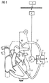
図1による概略図を参照して、本発明による脈動血液ポンプの基本原理は以下に説明される。脈動血液ポンプは、一方では第1の導管L1および第2の導管L2経由で血管に、ここでは大動脈AOに、他方では心腔に、ここでは左心室LVに、接続されている双方向ポンピングシステムから実質的に成る。双方向ポンピングシステムは、ポンプPとポンプPを駆動するモータMとから実質的に成る。特定の場合においてポンプおよび/またはモータが具体的にどのように構成され、互いに連結されるかは、本発明にとってあまり重要ではない。図1に示されている基本原理に不可欠であるのは、ポンプPが複動式ピストンシリンダ装置の方法で構成されていることであり、ピストンKはシリンダZの内部で行き来する方向に移動する。これにより、ピストンKにより分離されている背中合わせのポンピング室1および2内の容積V1およびV2が変化する。
With reference to the schematic diagram according to FIG. 1, the basic principle of a pulsating blood pump according to the present invention will be described below. The pulsating blood pump is connected on the one hand to the blood vessel via the first conduit L 1 and the second conduit L 2 , here to the aorta AO, on the other hand to the heart chamber, here to the left ventricle LV. Consists essentially of a pumping system. The bi-directional pumping system substantially consists of a pump P and a motor M that drives the pump P. It is not very important to the present invention how the pump and / or motor are specifically configured and connected to each other in certain cases. Essential to the basic principle shown in FIG. 1 is that the pump P is constructed in the manner of a double-acting piston-cylinder arrangement, and the piston K moves in the direction of traveling back and forth inside the cylinder Z. . As a result, the volumes V 1 and V 2 in the back-to-
モータM、およびしたがってポンプPは、制御手段Stにより、所定の心調律に従って、一方の方向に、また他方の方向に交互に動作する。ポンピングシステムを制御するための心調律データ(例えば、圧力、ECG、収縮、PPS等)は、制御手段Stと連結されているセンサ手段Sにより取得され、制御手段Stに送信され得る。このことは、圧力センサであってもよい、左心室LVの心房内にあるセンサSにより、ほんの概略的に図1に示されている。 The motor M and thus the pump P are alternately operated in one direction and in the other direction according to a predetermined cardiac rhythm by the control means St. Heart rhythm data (eg, pressure, ECG, contraction, PPS, etc.) for controlling the pumping system can be obtained by the sensor means S connected to the control means St and transmitted to the control means St. This is shown only schematically in FIG. 1 by a sensor S in the atrium of the left ventricle LV, which may be a pressure sensor.
ポンピングシステムを動作させるために必要なエネルギーは、エネルギー貯蔵デバイスEから利用可能にすることができ、当該エネルギー貯蔵デバイスは、例えば非接触で、トランスミッタTにより、継続的に、または好ましくは一時的に、のどちらかで、相応に充電される。 The energy required to operate the pumping system can be made available from the energy storage device E, which is, for example, contactless, continuously by the transmitter T, or preferably temporarily. The battery is charged accordingly.
このエネルギーを使用し、制御手段Stにより処理された心調律データを考慮して、収縮期の間にポンピング室1の容積V1が減少し血液がポンピング室1から外へ導管L1経由で左心室LV内へ相応に吐出されるように、ここでピストンKは心調律に従って変位する。したがって、血液が大動脈AOから外へ導管L2を通って第2のポンピング室2の増大している容積V2内に同時に吸引される。左心室LVは、このように、低下した大動脈圧に対抗して作用し、また、ポンピング室1から外へ移動した血液量は、左心室LVおよび大動脈弁を通って大動脈AO内へ流動する。後続の拡張期の間、ピストンKは反対方向に移動し、その結果、血液が左心室LVから外へ導管L1を通ってポンピング室1内に吸引され、同時に対応する量の血液が、第2のポンピング室2から外へ導管L2を通って大動脈AO内に吐出される。これにより、左心室LVの膨張が最小限になり、心臓の拡張に対抗し、その結果、心臓は回復することができる。同時に、大動脈AO内にそのように吐出された血液は大動脈AO内の血圧を上昇させるので、血液は器官内に、すなわち心臓内においても、かつ抹消血管内に確実に流れ込む。心室拡張サイズの減少により、心筋の壁応力が最小限になり、したがって心臓に血液がより効率的に供給されることが可能になる。
Using this energy and taking into account the cardiac rhythm data processed by the control means St, the volume V 1 of the
図2はこの基本原理の第1の変形形態を示す。ピストンKは、ここでは、異なる大きさの2つのピストン領域を備えた差動ピストンとして構成されている。したがって、方向RにおけるピストンKの運動時に、容積V1およびV2は同程度には変化しない。具体的に示されている例示的実施形態では、大動脈AOと第2のポンピング室2との間で吐出される量より少量の血液が、差動ピストンKに因り左心室LVとポンピング室1との間で行き来するよう吐出される。どの心臓機能が脈動血液ポンプにより主として支援されるべきかに応じて、差動ピストンのより大きなピストン領域が、心臓または血管のどちらかの側に存在し得る。しかし、差動ピストンKは、より小さいピストン領域の側において、導管L3経由でポンプPに接続されている付加コンプライアンス室Cを必要とする。コンプライアンス室Cは、差動ピストンKの変位方向に応じて正または負である、容積変位V2およびV1がもたらした差を吸収する。コンプライアンス室Cは患者体内の位置に配置され、そこではコンプライアンス室Cは、例えば腹部において、低い周囲圧力に晒されるのみであり、導管L3経由でポンプPに接続されている。導管L3およびコンプライアンス室C内には、液体すなわち詳細には血液ではないものが存在していることが好ましい。
FIG. 2 shows a first variant of this basic principle. The piston K is here configured as a differential piston with two piston regions of different sizes. Thus, during movement of piston K in direction R, volumes V 1 and V 2 do not change to the same extent. In the exemplary embodiment specifically shown, less blood than is discharged between the aorta AO and the
図3は、基本原理の第2の変形形態を示す。ここでは、第1のポンピング室1が、第1のコンプライアンス室C1と共に第1の複室を形成しており、第2のポンピング室2が、第2のコンプライアンス室C2と共に第2の複室を形成している。ポンピング室1および2はそれぞれ、膜M1およびM2により、コンプライアンス室C1およびC2から分離されており、その結果、ポンピング室1および2の容積V1およびV2はそれぞれ可変である。ポンプPの手段により、流体が心調律に従ってコンプライアンス室C1とC2との間で行き来するよう吐出され、2つのポンピング室1および2の可変容積V1およびV2が図1を参照して前述されている方法で変化する。ポンプPは、ここでは概略的に表されているだけであり、例として双方向回転ポンプであってもよい。この目的のために、ポンプPは、導管L4およびL5経由でコンプライアンス室C1およびC2に接続されている。導管L4、L5およびコンプライアンス室C1、C2内には、液圧装置の作動流体がいれられており、すなわち詳細には血液が入っていない。ポンプPは、このように、膜M1およびM2により血液循環から確実に遮断されている。このことは、ポンピングシステムに使用可能なポンプPの構造および効率性にとって有益である。同様に、それはポンピングシステムの疲労強度を大幅に向上させる。
FIG. 3 shows a second variant of the basic principle. Here, the
付加コンプライアンス室CVが設けられて、血液量V1およびV2の大きさが変化する場合に、容積変動を吸収することができる。図3は、コンプライアンス室C1とC2との間で吐出される流体の一部を吸収するそのような付加コンプライアンス室CVを示す。この付加コンプライアンス室CVは随意であり、そのコンプライアンス特性に関して可変的に調節可能であることが好ましい。コンプライアンス特性を調節するために、制御弁StVが使用される。調節は、埋込みの前にまたは好ましくは例えば遠隔制御によりやはり埋込み後に、のどちらかで、さらに必要に応じてまたは継続的に、のどちらかで、行うことができる。これにより、適用可能な場合、やはり動的に、ポンピング室1および2内に受容されている血液量を変化させることが可能になる。そのような対策の理由は、例えば、2つのポンピング室1および2の一方または他方の充填時に問題が起こること、またはポンピング室1および2の利用可能な容積が意図的に変えられることである可能性がある。このように、両ポンピング室1および2のための共通ポンプPにも関わらず、付属コンプライアンス室C1とC2との間で異なる量を吐出することが可能であり、差分量は付加コンプライアンス室CVにより吸収される。制御弁StVにより、このように、ポンピング室1および2の吸引量および駆出量を可変的に制御することが可能である。しかし、量の減少により、ポンピング室の一方に多量の血液が継続的に留まっているので連続的な血液凝集が懸念される、という結果が出てはならない。
When the additional compliance chamber C V is provided and the magnitudes of the blood volumes V 1 and V 2 change, the volume fluctuation can be absorbed. FIG. 3 shows such an additional compliance chamber C V that absorbs part of the fluid discharged between the compliance chambers C 1 and C 2 . This additional compliance chamber CV is optional and is preferably variably adjustable with respect to its compliance characteristics. A control valve StV is used to adjust the compliance characteristics. The adjustment can take place either before implantation or preferably after implantation, for example by remote control, and also as needed or continuously. This makes it possible to dynamically change the volume of blood received in the
導管L5に取り付けられている付加コンプライアンス室CVの代わりに、それはまた、導管L4に取り付けることができる。 Instead of additional compliance chamber C V, which is attached to the conduit L 5, it also can be attached to the conduit L 4.
最後に、図4は、図1に示されている基本原理のさらなる変形形態をさらに示す。ここでは、脈動血液ポンプの導管L1およびL2は、左心室LVおよび大動脈AOに接続されていないが、代わりに右心室RVおよび肺動脈PAに接続されている。 Finally, FIG. 4 further shows a further variant of the basic principle shown in FIG. Here, the pulsating blood pump conduits L 1 and L 2 are not connected to the left ventricle LV and the aorta AO, but instead are connected to the right ventricle RV and the pulmonary artery PA.
また、一方では心臓の左半分のために、他方では心臓の右半分のために、前述のタイプの2つの別個の脈動血液ポンプを同時に動作させる可能性がある。 It is also possible to operate two separate pulsating blood pumps of the aforementioned type simultaneously on the one hand for the left half of the heart and on the other hand for the right half of the heart.
Claims (8)
前記脈動血液ポンプを心腔(LV;RV)に接続する第1の導管(L1)と、
前記脈動血液ポンプを血管(AO;PA)に接続する第2の導管(L2)と、
第1の動作では前記第1の導管(L1)を通して血液を吸引しかつ同時に前記第2の導管(L2)を通して血液を駆出し、第2の動作では前記第2の導管(L2)を通して血液を吸引しかつ同時に前記第1の導管(L1)を通して血液を駆出するようにされている双方向ポンピングシステム(P;P、M)と、
所定の心調律に従って、心臓の拡張期の間に第1の動作を、心臓の収縮期の間に第2の動作を前記ポンピングシステム(P;P、M)に動作させるために設けられている制御手段(St)と、
を含むことを特徴とする血管外脈動血液ポンプ。 An extravascular pulsating blood pump,
A first conduit (L 1 ) connecting the pulsating blood pump to the heart chamber (LV; RV);
A second conduit (L 2 ) connecting the pulsating blood pump to a blood vessel (AO; PA);
In the first operation, blood is aspirated through the first conduit (L 1 ) and at the same time blood is expelled through the second conduit (L 2 ), and in the second operation, the second conduit (L 2 ). and; (P, M P), blood was aspirated and simultaneously the first conduit bidirectional pumping system that is adapted to ejection of blood through (L 1) through
According to a predetermined cardiac rhythm, the first operation during the diastole of the heart, the second operation during the cardiac systole the pumping system; provided in order to operate on (P P, M) Control means (St);
An extravascular pulsating blood pump comprising:
Applications Claiming Priority (3)
| Application Number | Priority Date | Filing Date | Title |
|---|---|---|---|
| DE102012207042.7 | 2012-04-27 | ||
| DE102012207042.7A DE102012207042B4 (en) | 2012-04-27 | 2012-04-27 | PULSATIONSBLUTPUMPE |
| PCT/EP2013/058648 WO2013160411A1 (en) | 2012-04-27 | 2013-04-25 | Pulsatile blood pump |
Publications (3)
| Publication Number | Publication Date |
|---|---|
| JP2015514530A JP2015514530A (en) | 2015-05-21 |
| JP2015514530A5 JP2015514530A5 (en) | 2016-06-02 |
| JP6058787B2 true JP6058787B2 (en) | 2017-01-11 |
Family
ID=48227262
Family Applications (1)
| Application Number | Title | Priority Date | Filing Date |
|---|---|---|---|
| JP2015507539A Active JP6058787B2 (en) | 2012-04-27 | 2013-04-25 | Pulsating blood pump |
Country Status (7)
| Country | Link |
|---|---|
| US (1) | US9555173B2 (en) |
| EP (1) | EP2841123B1 (en) |
| JP (1) | JP6058787B2 (en) |
| KR (1) | KR101926847B1 (en) |
| AU (1) | AU2013254650B2 (en) |
| DE (1) | DE102012207042B4 (en) |
| WO (1) | WO2013160411A1 (en) |
Families Citing this family (13)
| Publication number | Priority date | Publication date | Assignee | Title |
|---|---|---|---|---|
| WO2018226991A1 (en) | 2017-06-07 | 2018-12-13 | Shifamed Holdings, Llc | Intravascular fluid movement devices, systems, and methods of use |
| US11511103B2 (en) | 2017-11-13 | 2022-11-29 | Shifamed Holdings, Llc | Intravascular fluid movement devices, systems, and methods of use |
| DE102018201030A1 (en) | 2018-01-24 | 2019-07-25 | Kardion Gmbh | Magnetic coupling element with magnetic bearing function |
| US10722631B2 (en) | 2018-02-01 | 2020-07-28 | Shifamed Holdings, Llc | Intravascular blood pumps and methods of use and manufacture |
| EP3536955A1 (en) * | 2018-03-08 | 2019-09-11 | Berlin Heart GmbH | Drive device for a membrane fluid pump and operation method |
| DE102018211327A1 (en) | 2018-07-10 | 2020-01-16 | Kardion Gmbh | Impeller for an implantable vascular support system |
| JP2022524774A (en) | 2019-03-08 | 2022-05-10 | サマコア, インコーポレイテッド | Positive displacement shuttle pump heart and VAD |
| JP2022540616A (en) | 2019-07-12 | 2022-09-16 | シファメド・ホールディングス・エルエルシー | Intravascular blood pump and methods of manufacture and use |
| US11654275B2 (en) | 2019-07-22 | 2023-05-23 | Shifamed Holdings, Llc | Intravascular blood pumps with struts and methods of use and manufacture |
| WO2021062265A1 (en) | 2019-09-25 | 2021-04-01 | Shifamed Holdings, Llc | Intravascular blood pump systems and methods of use and control thereof |
| US11839708B2 (en) | 2019-10-19 | 2023-12-12 | SummaCor, Inc. | Linear cardiac assist pulsatile pump |
| DE102020102474A1 (en) | 2020-01-31 | 2021-08-05 | Kardion Gmbh | Pump for conveying a fluid and method for manufacturing a pump |
| CN116549762B (en) * | 2023-07-10 | 2023-10-31 | 北京悦唯医疗科技有限责任公司 | Left ventricle auxiliary device |
Family Cites Families (10)
| Publication number | Priority date | Publication date | Assignee | Title |
|---|---|---|---|---|
| US5314469A (en) * | 1992-03-11 | 1994-05-24 | Milwaukee Heart Research Foundation | Artificial heart |
| US20040230090A1 (en) * | 2002-10-07 | 2004-11-18 | Hegde Anant V. | Vascular assist device and methods |
| US7273446B2 (en) | 2003-10-31 | 2007-09-25 | Spence Paul A | Methods, devices and systems for counterpulsation of blood flow to and from the circulatory system |
| WO2007089500A2 (en) | 2006-01-30 | 2007-08-09 | Pong-Jeu Lu | Dual-pulsation bi-ventricular assist device |
| US20100268333A1 (en) * | 2009-04-16 | 2010-10-21 | Gohean Jeffrey R | System and method for controlling pump |
| DE102006035548B4 (en) * | 2006-07-27 | 2009-02-12 | Deutsches Zentrum für Luft- und Raumfahrt e.V. | artificial heart |
| JP5250755B2 (en) * | 2008-03-25 | 2013-07-31 | 株式会社サンメディカル技術研究所 | Assisted artificial heart pump drive device and assisted artificial heart system |
| EP2320968B1 (en) | 2008-08-05 | 2012-05-09 | Michigan Critical Care Consultants, Inc. | Apparatus and method for monitoring and controlling extracorporeal blood flow relative to patient fluid status |
| DE102010018233A1 (en) | 2010-04-23 | 2011-10-27 | Deutsches Zentrum für Luft- und Raumfahrt e.V. | Heart assist device |
| EP2388028A1 (en) * | 2010-05-20 | 2011-11-23 | Berlin Heart GmbH | Method for operating a pump system |
-
2012
- 2012-04-27 DE DE102012207042.7A patent/DE102012207042B4/en active Active
-
2013
- 2013-04-25 JP JP2015507539A patent/JP6058787B2/en active Active
- 2013-04-25 EP EP13719515.2A patent/EP2841123B1/en active Active
- 2013-04-25 US US14/396,718 patent/US9555173B2/en active Active
- 2013-04-25 KR KR1020147032328A patent/KR101926847B1/en active IP Right Grant
- 2013-04-25 WO PCT/EP2013/058648 patent/WO2013160411A1/en active Application Filing
- 2013-04-25 AU AU2013254650A patent/AU2013254650B2/en active Active
Also Published As
| Publication number | Publication date |
|---|---|
| KR20150008135A (en) | 2015-01-21 |
| WO2013160411A1 (en) | 2013-10-31 |
| DE102012207042A1 (en) | 2013-10-31 |
| KR101926847B1 (en) | 2018-12-07 |
| AU2013254650A1 (en) | 2014-11-13 |
| EP2841123B1 (en) | 2016-07-06 |
| EP2841123A1 (en) | 2015-03-04 |
| DE102012207042B4 (en) | 2017-09-07 |
| US20150133722A1 (en) | 2015-05-14 |
| JP2015514530A (en) | 2015-05-21 |
| AU2013254650B2 (en) | 2016-12-22 |
| US9555173B2 (en) | 2017-01-31 |
Similar Documents
| Publication | Publication Date | Title |
|---|---|---|
| JP6058787B2 (en) | Pulsating blood pump | |
| US9504773B2 (en) | Methods and systems for counterpulsation of blood flow to and from the circulatory system | |
| CA2916350C (en) | Artificial ventricles | |
| US5300113A (en) | Cardiac ventricular assistance device particularly for compensating for weakened heart muscle function and for maintaining the vital body functions | |
| WO2003068292A1 (en) | Physiologically compatible cardiac assist device and method | |
| JP2021500196A (en) | How to control the catheter pump system and catheter pump drive | |
| JP6895507B2 (en) | Intra-aortic dual balloon driven pumping catheter device | |
| CA2762200C (en) | Actuating mechanism for pneumatically-driven artificial heart | |
| US20180064864A1 (en) | Artificial Ventricles | |
| Moulopoulos | The limits of counterpulsation | |
| JP2018502691A (en) | An assembly comprising a suction line, a discharge line and a pump | |
| KR101105818B1 (en) | Emergency measure device using blood pump and method for using thereof | |
| CN114209977A (en) | Intracardiac pump, ventricular assist system and method for operating intracardiac assist system |
Legal Events
| Date | Code | Title | Description |
|---|---|---|---|
| A521 | Request for written amendment filed |
Free format text: JAPANESE INTERMEDIATE CODE: A523 Effective date: 20160406 |
|
| A621 | Written request for application examination |
Free format text: JAPANESE INTERMEDIATE CODE: A621 Effective date: 20160406 |
|
| A871 | Explanation of circumstances concerning accelerated examination |
Free format text: JAPANESE INTERMEDIATE CODE: A871 Effective date: 20160406 |
|
| A975 | Report on accelerated examination |
Free format text: JAPANESE INTERMEDIATE CODE: A971005 Effective date: 20160530 |
|
| A131 | Notification of reasons for refusal |
Free format text: JAPANESE INTERMEDIATE CODE: A131 Effective date: 20160607 |
|
| A521 | Request for written amendment filed |
Free format text: JAPANESE INTERMEDIATE CODE: A523 Effective date: 20160907 |
|
| TRDD | Decision of grant or rejection written | ||
| A01 | Written decision to grant a patent or to grant a registration (utility model) |
Free format text: JAPANESE INTERMEDIATE CODE: A01 Effective date: 20161115 |
|
| A61 | First payment of annual fees (during grant procedure) |
Free format text: JAPANESE INTERMEDIATE CODE: A61 Effective date: 20161207 |
|
| R150 | Certificate of patent or registration of utility model |
Ref document number: 6058787 Country of ref document: JP Free format text: JAPANESE INTERMEDIATE CODE: R150 |
|
| R250 | Receipt of annual fees |
Free format text: JAPANESE INTERMEDIATE CODE: R250 |
|
| R250 | Receipt of annual fees |
Free format text: JAPANESE INTERMEDIATE CODE: R250 |
|
| R250 | Receipt of annual fees |
Free format text: JAPANESE INTERMEDIATE CODE: R250 |
|
| R250 | Receipt of annual fees |
Free format text: JAPANESE INTERMEDIATE CODE: R250 |
|
| R250 | Receipt of annual fees |
Free format text: JAPANESE INTERMEDIATE CODE: R250 |