JP6057915B2 - Method and apparatus for applying a liquid reaction mixture to a cover layer - Google Patents
Method and apparatus for applying a liquid reaction mixture to a cover layer Download PDFInfo
- Publication number
- JP6057915B2 JP6057915B2 JP2013547847A JP2013547847A JP6057915B2 JP 6057915 B2 JP6057915 B2 JP 6057915B2 JP 2013547847 A JP2013547847 A JP 2013547847A JP 2013547847 A JP2013547847 A JP 2013547847A JP 6057915 B2 JP6057915 B2 JP 6057915B2
- Authority
- JP
- Japan
- Prior art keywords
- outer layer
- pipe
- reaction mixture
- openings
- opening
- Prior art date
- Legal status (The legal status is an assumption and is not a legal conclusion. Google has not performed a legal analysis and makes no representation as to the accuracy of the status listed.)
- Expired - Fee Related
Links
Images


Classifications
-
- B—PERFORMING OPERATIONS; TRANSPORTING
- B29—WORKING OF PLASTICS; WORKING OF SUBSTANCES IN A PLASTIC STATE IN GENERAL
- B29C—SHAPING OR JOINING OF PLASTICS; SHAPING OF MATERIAL IN A PLASTIC STATE, NOT OTHERWISE PROVIDED FOR; AFTER-TREATMENT OF THE SHAPED PRODUCTS, e.g. REPAIRING
- B29C44/00—Shaping by internal pressure generated in the material, e.g. swelling or foaming ; Producing porous or cellular expanded plastics articles
- B29C44/34—Auxiliary operations
- B29C44/36—Feeding the material to be shaped
- B29C44/46—Feeding the material to be shaped into an open space or onto moving surfaces, i.e. to make articles of indefinite length
- B29C44/461—Feeding the material to be shaped into an open space or onto moving surfaces, i.e. to make articles of indefinite length dispensing apparatus, e.g. dispensing foaming resin over the whole width of the moving surface
-
- B—PERFORMING OPERATIONS; TRANSPORTING
- B05—SPRAYING OR ATOMISING IN GENERAL; APPLYING FLUENT MATERIALS TO SURFACES, IN GENERAL
- B05D—PROCESSES FOR APPLYING FLUENT MATERIALS TO SURFACES, IN GENERAL
- B05D1/00—Processes for applying liquids or other fluent materials
- B05D1/26—Processes for applying liquids or other fluent materials performed by applying the liquid or other fluent material from an outlet device in contact with, or almost in contact with, the surface
-
- B—PERFORMING OPERATIONS; TRANSPORTING
- B05—SPRAYING OR ATOMISING IN GENERAL; APPLYING FLUENT MATERIALS TO SURFACES, IN GENERAL
- B05C—APPARATUS FOR APPLYING FLUENT MATERIALS TO SURFACES, IN GENERAL
- B05C5/00—Apparatus in which liquid or other fluent material is projected, poured or allowed to flow on to the surface of the work
- B05C5/02—Apparatus in which liquid or other fluent material is projected, poured or allowed to flow on to the surface of the work the liquid or other fluent material being discharged through an outlet orifice by pressure, e.g. from an outlet device in contact or almost in contact, with the work
- B05C5/0245—Apparatus in which liquid or other fluent material is projected, poured or allowed to flow on to the surface of the work the liquid or other fluent material being discharged through an outlet orifice by pressure, e.g. from an outlet device in contact or almost in contact, with the work for applying liquid or other fluent material to a moving work of indefinite length, e.g. to a moving web
-
- B—PERFORMING OPERATIONS; TRANSPORTING
- B29—WORKING OF PLASTICS; WORKING OF SUBSTANCES IN A PLASTIC STATE IN GENERAL
- B29C—SHAPING OR JOINING OF PLASTICS; SHAPING OF MATERIAL IN A PLASTIC STATE, NOT OTHERWISE PROVIDED FOR; AFTER-TREATMENT OF THE SHAPED PRODUCTS, e.g. REPAIRING
- B29C44/00—Shaping by internal pressure generated in the material, e.g. swelling or foaming ; Producing porous or cellular expanded plastics articles
- B29C44/34—Auxiliary operations
- B29C44/36—Feeding the material to be shaped
- B29C44/46—Feeding the material to be shaped into an open space or onto moving surfaces, i.e. to make articles of indefinite length
-
- B—PERFORMING OPERATIONS; TRANSPORTING
- B05—SPRAYING OR ATOMISING IN GENERAL; APPLYING FLUENT MATERIALS TO SURFACES, IN GENERAL
- B05B—SPRAYING APPARATUS; ATOMISING APPARATUS; NOZZLES
- B05B1/00—Nozzles, spray heads or other outlets, with or without auxiliary devices such as valves, heating means
- B05B1/02—Nozzles, spray heads or other outlets, with or without auxiliary devices such as valves, heating means designed to produce a jet, spray, or other discharge of particular shape or nature, e.g. in single drops, or having an outlet of particular shape
- B05B1/04—Nozzles, spray heads or other outlets, with or without auxiliary devices such as valves, heating means designed to produce a jet, spray, or other discharge of particular shape or nature, e.g. in single drops, or having an outlet of particular shape in flat form, e.g. fan-like, sheet-like
-
- B—PERFORMING OPERATIONS; TRANSPORTING
- B05—SPRAYING OR ATOMISING IN GENERAL; APPLYING FLUENT MATERIALS TO SURFACES, IN GENERAL
- B05C—APPARATUS FOR APPLYING FLUENT MATERIALS TO SURFACES, IN GENERAL
- B05C5/00—Apparatus in which liquid or other fluent material is projected, poured or allowed to flow on to the surface of the work
- B05C5/02—Apparatus in which liquid or other fluent material is projected, poured or allowed to flow on to the surface of the work the liquid or other fluent material being discharged through an outlet orifice by pressure, e.g. from an outlet device in contact or almost in contact, with the work
- B05C5/027—Coating heads with several outlets, e.g. aligned transversally to the moving direction of a web to be coated
-
- Y—GENERAL TAGGING OF NEW TECHNOLOGICAL DEVELOPMENTS; GENERAL TAGGING OF CROSS-SECTIONAL TECHNOLOGIES SPANNING OVER SEVERAL SECTIONS OF THE IPC; TECHNICAL SUBJECTS COVERED BY FORMER USPC CROSS-REFERENCE ART COLLECTIONS [XRACs] AND DIGESTS
- Y10—TECHNICAL SUBJECTS COVERED BY FORMER USPC
- Y10T—TECHNICAL SUBJECTS COVERED BY FORMER US CLASSIFICATION
- Y10T428/00—Stock material or miscellaneous articles
- Y10T428/31504—Composite [nonstructural laminate]
- Y10T428/31551—Of polyamidoester [polyurethane, polyisocyanate, polycarbamate, etc.]
- Y10T428/31605—Next to free metal
Description
本発明は、外層を連続的に動かしながら液体反応混合物を該外層に塗布するための外層に液体反応混合物を塗布する装置であって、該装置が、該外層の方向に設けられた複数の開口部b)を有し、また該外層の面に平行にまた該外層の移動方向に直角に該外層の上に設けられた少なくとも一本のパイプa)を有し、該パイプの外層端部の上に位置する側の外側開口部が、外層端部の方向に1〜50°のある角度で設けられている装置に関する。 The present invention is an apparatus for applying a liquid reaction mixture to an outer layer for applying the liquid reaction mixture to the outer layer while continuously moving the outer layer, the apparatus comprising a plurality of openings provided in the direction of the outer layer. Part b), and having at least one pipe a) provided on the outer layer parallel to the surface of the outer layer and perpendicular to the direction of movement of the outer layer, at the end of the outer layer of the pipe The present invention relates to an apparatus in which the upper outer opening is provided at an angle of 1-50 ° in the direction of the outer layer end.
本発明はまた、上記装置の複合材料の製造のための利用、また外層への液体反応混合物の塗布のための利用に関する。本発明はまた、外層に液体反応混合物を上記装置を用いて、該外層を連続的に動かしながら該液体反応混合物をこの外層に塗布する複合材料の製造方法に関する。 The invention also relates to the use of the above device for the production of composite materials and for the application of a liquid reaction mixture to the outer layer. The present invention also relates to a method for producing a composite material in which a liquid reaction mixture is applied to an outer layer using the above-mentioned apparatus, while the liquid reaction mixture is applied to the outer layer while continuously moving the outer layer.
複合材料の製造、特に金属外層とイソシアネート系発泡体材料製の芯材(通常、ポリウレタン(PUR)またはポリイソシアヌレート(PIR)発泡体材料、ともにPU発泡体と称す)とからなる複合材料(しばしばサンドイッチ材料とも呼ばれる)の製造は、現在、二枚ベルト装置の連続運転により大規模に実施されている。冷蔵庫の断熱のためのサンドイッチ材料に加えて、いろいろな建物の外面建設用の材料の重要性が増加している。シャッター型のドアも、サンドイッチ材料からより多く製造されるようになってきている。塗装鋼板に加えて、ステンレス鋼、銅またはアルミニウム板も外層として使用されている。 Manufacture of composite materials, especially composite materials consisting of an outer metal layer and a core made of an isocyanate-based foam material (usually called polyurethane (PUR) or polyisocyanurate (PIR) foam material, both PU foam)) (often The production of sandwich materials (also called sandwich materials) is currently carried out on a large scale by continuous operation of a two-belt device. In addition to sandwich materials for refrigerator insulation, the importance of various building exterior materials is increasing. More shutter-type doors are also being manufactured from sandwich materials. In addition to painted steel plates, stainless steel, copper or aluminum plates are also used as outer layers.
イソシアネート系発泡体の製造では、先ず発泡体の液体出発成分であるポリオール成分とイソシアネート成分が、例えば混合ヘッド中で混合され、アプリケーターにより外層に塗布され、これらの成分がここで相互に反応し発泡してその発泡体を形成する。外層への塗布がうまく進むように有孔パイプが外層の上に設けられ、これが通常アプリケーターとして用いられる。これらのパイプは、以下、塗布レーキ、あるいはより簡単にレーキとよぶことがある。 In the production of an isocyanate-based foam, a polyol component and an isocyanate component, which are liquid starting components of the foam, are first mixed in, for example, a mixing head and applied to the outer layer by an applicator, and these components react with each other and foam. To form the foam. A perforated pipe is provided on the outer layer for successful application to the outer layer, which is usually used as an applicator. These pipes may hereinafter be referred to as application rakes or more simply rakes.
この場合、アプリケーターを外層上で可動な状態に設けて、往復運動により外層の全面にこの反応混合物を塗布することもできる。 In this case, the reaction mixture can be applied to the entire surface of the outer layer by a reciprocating motion by providing the applicator in a movable state on the outer layer.
最近、外層上に固定した状態で設けられたパイプも使用されている。このような装置は、例えばWO2009/077490、WO2008/104492またはWO2008/018787に記載されている。 Recently, pipes provided in a fixed state on the outer layer have also been used. Such devices are described, for example, in WO2009 / 077490, WO2008 / 104492 or WO2008 / 018787.
これらの装置は、通常金属製であり、好ましくはスチール製である。このような装置は機械的に極めて安定であるが、例えば反応後にポリウレタンがその上に固化して汚れると洗浄に手間がかかる。 These devices are usually made of metal, preferably steel. Such an apparatus is mechanically very stable. However, for example, if polyurethane is solidified and contaminated after the reaction, it takes time for cleaning.
DE202009015838.1にはまた、固化析出が起こると交換可能なあるいは廃棄可能なプラスチック製アプリケーターが記載されている。これにより、装置停止時間を短縮することができる。 DE 202009015838.1 also describes a plastic applicator that can be replaced or discarded when solidification occurs. Thereby, the apparatus stop time can be shortened.
通常のアプリケーターでは、外層端部での反応混合物塗布が不満足であることがわかっている。これは、下の外層が複雑な形状をしている場合に特に顕著である。このような形状が存在する場合、そこに反応混合物が上から投入できないデッドスペースが生成する。アプリケーターの位置が外層の末端に近すぎる場合、反応混合物が外層に沿って流れ、このため製品のロスや装置の汚染を引き起こすことがある。この欠点を克服するためにアプリケーターを外層の末端から比較的離れた位置に置くと、反応混合物が末端に届かず、品質上の問題を引き起こす可能性がある。 In normal applicators, application of the reaction mixture at the outer layer edge has been found to be unsatisfactory. This is particularly noticeable when the lower outer layer has a complex shape. When such a shape exists, a dead space in which the reaction mixture cannot be introduced from above is generated. If the applicator is positioned too close to the end of the outer layer, the reaction mixture may flow along the outer layer, thus causing product loss and equipment contamination. If the applicator is placed relatively far from the end of the outer layer to overcome this drawback, the reaction mixture may not reach the end and may cause quality problems.
本発明の目的は、複合材料の製造方法、特に金属外層とPU発泡体芯材からなる複合材料の製造方法を改善し、これにより、凹凸のある外層の場合であっても、そのデッド領域に反応混合物をより均一な分布で直接塗布できるようにすることである。特にPU発泡体の液体出発化合物を外層上に均一に分布できるとともに、得られる複合材料の品質が優れていることが必要である。 The object of the present invention is to improve a method for producing a composite material, particularly a method for producing a composite material comprising a metal outer layer and a PU foam core material. It is to be able to apply the reaction mixture directly with a more uniform distribution. In particular, it is necessary that the liquid starting compound of the PU foam can be uniformly distributed on the outer layer and the quality of the resulting composite material is excellent.
驚くべきことに、本目的が、外層の端部の上に位置するアプリケーター(塗布装置)に、複数の開口部を外層端部の方向に対して1〜50°のある角度で設けることで達成されることが明らかとなった。 Surprisingly, this object is achieved by providing a plurality of openings at an angle of 1-50 ° with respect to the direction of the outer layer end in the applicator (applicator) located above the end of the outer layer. It became clear that
したがって、本発明の対象は、外層を連続的に動かしながら液体反応混合物を該外層に塗布するための外層に液体反応混合物を塗布する装置であって、該装置が、該外層の方向に設けられた複数の開口部b)を有し、また該外層の面に平行にまた該外層の移動方向に直角に該外層の上に設けられた少なくとも一本のパイプa)を有し、該パイプの外層端部の上に位置する側の外側開口部が、外層端部の方向に1〜50°のある角度で設けられている装置である。 Accordingly, an object of the present invention is an apparatus for applying a liquid reaction mixture to an outer layer for applying the liquid reaction mixture to the outer layer while continuously moving the outer layer, the apparatus being provided in the direction of the outer layer. A plurality of openings b) and at least one pipe a) provided on the outer layer parallel to the surface of the outer layer and perpendicular to the direction of movement of the outer layer, In the device, the outer opening on the side located on the outer layer end is provided at an angle of 1 to 50 ° in the direction of the outer layer end.
本発明のある好ましい実施様態では、外層端部の上に位置する外側開口部b)1〜4が、外層端部の方向に1〜50°のある角度で設けられている。 In a preferred embodiment of the invention, the outer openings b) 1 to 4 located above the outer layer end are provided at an angle of 1 to 50 ° in the direction of the outer layer end.
液体反応混合物の供給は、パイプa)の中央で行われることが好ましい。原理的には、この反応混合がこのパイプの一端で起こってもよい。この場合にはパイプ内に過剰な圧力の蓄積があるかもしれないので、この実施様態は好ましくない。 The liquid reaction mixture is preferably fed at the center of the pipe a). In principle, this reaction mixing may take place at one end of the pipe. This embodiment is not preferred because in this case there may be excessive pressure buildup in the pipe.
パイプa)の中央で液体反応混合物の供給を行う場合、開口部b)は、対称的であっても非対称的であってもよい。対称的な配列とは、供給の両側で開口部b)が同じように配置されていることを意味し、すなわち、各側に同数の開口部b)があり、それぞれ中央から同じ距離にあることを意味する。 When the liquid reaction mixture is fed at the center of the pipe a), the opening b) may be symmetric or asymmetric. Symmetrical arrangement means that the openings b) are arranged in the same way on both sides of the supply, i.e. there are the same number of openings b) on each side, each at the same distance from the center. Means.
開口部b)の非対称的な配列では、供給の両側で開口部b)が異なって設けられている。この場合に、ある角度で設けられる開口部b)が、相互に異なっていることが好ましい。この実施様態は、特に外層端部が異なる輪郭を持つ場合に使用される。この場合、1個、2個、3個のまたは4個の開口部b)を両側に、相互に違えて、外層端部の方向に1〜50°で設けることができる。この実施様態では、外層端部により複雑な形状を持つものにも、発泡体を供給することができる。したがってある実施様態においては、このアプリケーターが、一個の開口部b)を片側に持ち、3個の開口部b)を他側に持つことができる。 In an asymmetric arrangement of the openings b), the openings b) are provided differently on both sides of the supply. In this case, the openings b) provided at a certain angle are preferably different from one another. This embodiment is used particularly when the outer layer ends have different contours. In this case, one, two, three or four openings b) can be provided on both sides at 1 to 50 ° in the direction of the outer layer edge, differing from each other. In this embodiment, the foam can be supplied even to those having a complicated shape at the end of the outer layer. Thus, in one embodiment, the applicator can have one opening b) on one side and three openings b) on the other side.
この実施様態においては、このアプリケーターは、上述のように対称的でなく、そのため反応混合物を不均一に排出する。難しい形状のパネルを完全充填したい場合に、これが有利となる。これは、特にシャッター型ドア(セクショナルドア)用のパネルの製造で有利である。 In this embodiment, the applicator is not symmetrical as described above and therefore discharges the reaction mixture non-uniformly. This is advantageous when it is desired to completely fill a difficult-shaped panel. This is particularly advantageous in the manufacture of panels for shutter type doors (sectional doors).
開口部b)が対称的な配列と非対称的な配列の場合の両方で、パイプa)の中央に、即ち液体反応混合物が投入される位置に開口部b)を設けることができる。これにより、いろいろな形状に、即ちいろいろな板の幾何形状に適応できる。これは、屋根の形状の場合や、シャッター型ドアのパネル上にあるような小ビーズの場合に特に有利である。反応混合物がこの小ビーズに直接塗布されないと、その領域で、基材欠陥及び/又は空気混入の問題が発生することがある。 In both cases where the openings b) are symmetric and asymmetric, openings b) can be provided in the center of the pipe a), i.e. where the liquid reaction mixture is introduced. This makes it possible to adapt to various shapes, that is, various plate geometries. This is particularly advantageous in the case of roof shapes and small beads such as those on shutter-type door panels. If the reaction mixture is not applied directly to the beadlets, substrate defects and / or aeration problems may occur in that area.
ある角度で複数の開口部b)が設けられる場合、この角度が外層端部の方向に大きくすることが好ましい。これにより、パイプa)の構造(配置構成)の幅を狭くすることができる。これにより洗浄が容易となる。またこの実施様態でより広い領域の塗布が可能となる。外層に対するパイプa)の高さを調整することで、塗布幅を変更可能である。パイプa)を高く設けられるほど、塗布幅が広くなる。これにより、このパイプa)が普遍的に(総括的に)使用可能となる。塗布幅は高さで調整可能であるため、考慮すべきはパイプa)の塗布幅ではなく、塗布速度である。 When a plurality of openings b) are provided at an angle, it is preferable that this angle be increased in the direction of the outer layer end. Thereby, the width | variety of the structure (arrangement structure) of the pipe a) can be narrowed . This facilitates cleaning. Further, in this embodiment, a wider area can be applied. The application width can be changed by adjusting the height of the pipe a) relative to the outer layer. The higher the pipe a), the wider the application width. As a result, the pipe a) can be used universally (generally) . Since the coating width can be adjusted by the height, what should be considered is not the coating width of the pipe a) but the coating speed.
この点で、外側開口部b)の角度の大きさは、次式により決めることが好ましい。
小角度=大角度/ある角度で設けられた開口部の数
即ち、開口部b)が2個の場合、小角度の値は、大角度の1/2であり、開口部b)が3個の場合、小角度は、最大角度の1/3であり、開口部b)が4個の場合、小角度は、最大角度の1/4である。
In this respect, it is preferable that the angle of the outer opening b) is determined by the following equation.
Small angle = large angle / number of openings provided at a certain angle
That is, when there are two openings b), the value of the small angle is ½ of the large angle, and when there are three openings b), the small angle is 3 of the maximum angle, If there are four openings b), the small angle is 1/4 of the maximum angle.
開口部b)の相互距離は、好ましくは2〜200mmである。本発明の特定の実施様態では、ある角度で設けられた開口部b)間の距離が2mm未満であってもよい。しかしこの場合でも、この距離は通常は1mm以上である。 The mutual distance of the openings b) is preferably 2 to 200 mm. In a particular embodiment of the invention, the distance between the openings b) provided at an angle may be less than 2 mm. However, even in this case, this distance is usually 1 mm or more.
ある角度で設けられる開口部b)は、相互に、あるいはある角度で設けられない開口部b)から同じ距離で設けられてもよい。 The openings b) provided at a certain angle may be provided at the same distance from each other or from openings b) not provided at a certain angle.
ある角度で設けられる開口部b)を相互に同じ距離で設け、ある角度で設けられない開口部b)から異なる距離で、好ましくはより小さな離で設けることもできる。 It is also possible to provide openings b) provided at a certain angle at the same distance from each other and at different distances, preferably at a smaller distance from openings b) not provided at a certain angle.
この場合、開口部b)の角度が大きくなると、開口部b)の間の距離を小さく選ぶことが好ましい。 In this case, it is preferable to select a smaller distance between the openings b) as the angle of the openings b) increases.
開口部b)の直径は、0.1〜10mmの範囲にあることが好ましい。この孔径は、好ましくは1〜6mmであり、特に1.5〜4mmである。 The diameter of the opening b) is preferably in the range of 0.1 to 10 mm. This hole diameter is preferably 1 to 6 mm, in particular 1.5 to 4 mm.
これらの直径が、全体のパイプa)にわたって一定であってもよい。本発明の特定の実施様態では、開口部b)の直径が、パイプa)の長さ方向で変化してもよい。これは、特に個々の領域で、特に外層端部領域でどれほどの量の発泡体が必要であるかによる。 These diameters may be constant over the entire pipe a). In a particular embodiment of the invention, the diameter of the opening b) may vary in the length direction of the pipe a). This depends on how much foam is required, especially in the individual areas, especially in the outer edge areas.
原則として、孔径b)は、パイプa)全体にわたり変動可能である。 In principle, the pore diameter b) can be varied throughout the pipe a).
本発明のある実施様態では、開口部b)の径が外層端部の方向に減少する。本発明のもう一つの実施様態では、開口部b)の径が外層端部の方向に増加する。本発明のある実施様態では、ある角度で設けられた開口部b)が他のものより小さな直径をもつ。 In one embodiment of the invention, the diameter of the opening b) decreases in the direction of the outer layer end. In another embodiment of the invention, the diameter of the opening b) increases in the direction of the outer layer end. In one embodiment of the invention, the opening b) provided at an angle has a smaller diameter than the others.
本発明の他の好ましい実施様態では、液体反応混合物が各開口部から同じ速度で排出されるように開口部b)が設計される。これは、例えば開口部b)の直径を変化させて行うことができる。ある好ましい実施様態においては、これが開口部の長さを変化させて行われる。なお、この開口部の長さは、開口部b)が設けられているパイプa)の内側から反応混合物がアプリケーターから排出される点までの距離を意味するものとする。 In another preferred embodiment of the invention, the openings b) are designed so that the liquid reaction mixture is discharged from each opening at the same rate. This can be done, for example, by changing the diameter of the opening b). In one preferred embodiment, this is done by changing the length of the opening. The length of the opening means the distance from the inside of the pipe a) where the opening b) is provided to the point where the reaction mixture is discharged from the applicator.
排出速度を均一にするため、開口部b)の長さは、反応混合物の供給場所からパイプa)の末端領域へ向かって減少している。 In order to make the discharge rate uniform, the length of the opening b) decreases from the feeding location of the reaction mixture towards the end region of the pipe a).
パイプa)の外径を一定として、パイプa)の内径を中央から減少させることで、開口部b)の長さを変化させることができる。しかし、この実施様態は製造が難しいため好ましくない。 The length of the opening b) can be changed by reducing the inner diameter of the pipe a) from the center while keeping the outer diameter of the pipe a) constant. However, this embodiment is not preferred because it is difficult to manufacture.
パイプa)の径は、好ましくは0.2〜5cmである。 The diameter of the pipe a) is preferably 0.2-5 cm.
本発明のある実施様態では、開口部b)が設けられた側のパイプa)を、開口部b)の長さが大きくなるように変更することで、開口部bの長さを変えることができる。この実施様態を、以下により詳細に説明する。 In one embodiment of the present invention, the length of the opening b can be changed by changing the pipe a) on the side provided with the opening b) so that the length of the opening b) is increased. it can. This embodiment is described in more detail below.
本発明のある実施様態では、2個以上のパイプa)も使用することができ、特に2個のパイプa)を相互に並べて使用できる。これは、特に非常に広い外層の場合に有利である。 In one embodiment of the invention, two or more pipes a) can also be used, in particular two pipes a) can be used side by side. This is particularly advantageous for very wide outer layers.
パイプa)は金属製であってよい。なお、スチール、特にステンレス鋼が好ましい。この実施様態は、その高い機械的安定性に特徴がある。 Pipe a) may be made of metal. Steel, particularly stainless steel is preferred. This embodiment is characterized by its high mechanical stability.
この実施様態の場合、開口部b)の長さは、適当な長さと厚みの平坦な金属部品をパイプa)に溶接することで変更できる。この溶接金属部品を、例えば研磨により開口部の長さに段階的に調整する。開口部b)は、特に穿孔により設けられ、次いで好ましくはバリ取りされる。次いで、この装置を硬化させもよい。このために、他の製造方法も可能である。 In this embodiment, the length of the opening b) can be changed by welding a flat metal part with a suitable length and thickness to the pipe a). The weld metal part is adjusted stepwise to the length of the opening by, for example, polishing. The opening b) is provided in particular by drilling and then preferably deburred. The device may then be cured. For this reason, other manufacturing methods are possible.
装置の運転中に、反応生成物による汚れが起こる。したがって、この装置は、定期的に洗浄する必要があり、特に溶媒を用いて洗浄する必要がある。 During operation of the apparatus, contamination with reaction products occurs. Therefore, this apparatus needs to be periodically cleaned, particularly using a solvent.
本発明のもう一つの実施様態では、パイプa)がプラスチック製である。なお、熱可塑性樹脂が好ましい。安全の理由で発泡体の製造に易燃性炭化水素が発泡剤として使用されることが多いため、このプラスチックが静電気的に帯電されないようにする必要がある。 In another embodiment of the invention, the pipe a) is made of plastic. A thermoplastic resin is preferred. For reasons of safety, flammable hydrocarbons are often used as blowing agents in the production of foams, so it is necessary to prevent this plastic from being electrostatically charged.
このプラスチックは、好ましくはポリアミドまたはポリオキシメチレン(POM)であり、特にポリアミドである。機械的安定性を改善するため、これらのプラスチックを充填剤で強化してもよい。この一例がガラス繊維強化ポリアミドである。 This plastic is preferably polyamide or polyoxymethylene (POM), in particular polyamide. These plastics may be reinforced with fillers to improve mechanical stability. An example of this is glass fiber reinforced polyamide.
プラスチック製のパイプa)は、射出成型で製造することが好ましい。 The plastic pipe a) is preferably produced by injection molding.
プラスチックを使用する場合、金属を使用する場合と比べると重量が低下する。また、多数個を製造すると低コストとなる。この装置が汚れると、これを廃棄し新しい装置と交換できる。 When plastic is used, the weight is lower than when using metal. Moreover, when many pieces are manufactured, the cost becomes low. If this device becomes dirty, it can be discarded and replaced with a new device.
本発明のある実施様態では、開口部b)を備えたパイプa)が少なくとも2本、特に直線状と配置されたものが使用される。2〜4本のパイプを使用することが好ましく、特に好ましくは2〜3本、特に2本のパイプa)の使用が好ましい。多くのパイプa)を使用する場合、開口部b)は、外層端部上に位置する側のみにある角度で設けられる。 In one embodiment of the invention, at least two pipes a) with openings b) are used, in particular those arranged in a straight line. It is preferred to use 2 to 4 pipes, particularly preferably 2 to 3 and especially 2 pipes a). When many pipes a) are used, the opening b) is provided at an angle only on the side located on the outer layer end.
このアプリケーターは、下の外層の上に、高さが1〜40cmで、好ましくは10〜30cm、及び特に15〜25cmで設けられることが好ましい。正確な距離は、外層の形状に応じて決定する必要があり、したがって変動する。 The applicator is preferably provided on the lower outer layer with a height of 1 to 40 cm, preferably 10 to 30 cm and especially 15 to 25 cm. The exact distance needs to be determined according to the shape of the outer layer and therefore varies.
パイプa)、または相互に隣り合って設けられる複数のパイプa)は合計で、外層の幅と等しい長さをもっていてもよい。しかしながら、これは外層にそって流れた製品を与えるため、好ましくない。 The pipe a) or a plurality of pipes a) provided adjacent to each other may have a total length equal to the width of the outer layer. However, this is undesirable because it gives a product that flows along the outer layer.
したがって安全のためには、パイプa)長は、外層の幅より小さいことが好ましい。この場合、このパイプa)は、外層全体の中心に設けられる。塗布レーキは、外層の幅の少なくとも60%を、特に70%をカバーすることが好ましい。通常サンドイッチ材料の場合のように、外層の幅が1.20mである場合、各辺の幅の18cmが、塗布レーキでカバーされないだろう。この塗布レーキが、あるいは隣接して設けられる複数の塗布レーキが、外層の幅の少なくとも60%、特に少なくとも70%をカバーすることが好ましい。ある角度で設けられた孔b)があると、孔b)が設けられていないものと比べて、パイプa)の長さを短くすることができる。 Therefore, for safety, the length of the pipe a) is preferably smaller than the width of the outer layer. In this case, this pipe a) is provided at the center of the entire outer layer. The coating rake preferably covers at least 60% of the width of the outer layer, in particular 70%. If the width of the outer layer is 1.20 m, as is usually the case with sandwich materials, 18 cm of the width of each side will not be covered by the coating rake. It is preferred that this coating rake or a plurality of coating rakes provided adjacently cover at least 60%, in particular at least 70% of the width of the outer layer. If there is a hole b) provided at an angle, the length of the pipe a) can be shortened compared to the case where the hole b) is not provided.
この液体反応混合物は、イソシアネート系発泡体の製造用のもの、特にポリウレタン発泡体とポリイソシアヌレート発泡体の製造用のものであることが好ましい。周知の如く、これらは、ポリイソシアネートを発泡剤の存在下でイソシアネート基と反応する少なくとも2個の水素原子をもつ化合物と反応させて製造される。これらの成分は、通常の混合装置中で、例えば高圧混合ヘッドまたは低圧混合ヘッド中で混合され、パイプa)に送られる。 This liquid reaction mixture is preferably for the production of isocyanate foams, in particular for the production of polyurethane foams and polyisocyanurate foams. As is well known, these are prepared by reacting a polyisocyanate with a compound having at least two hydrogen atoms which reacts with isocyanate groups in the presence of a blowing agent. These components are mixed in a conventional mixing device, for example in a high-pressure mixing head or a low-pressure mixing head, and sent to pipe a).
これは通常、混合装置とパイプa)の間に設けられた連結部により行われる。この連結部は、好ましくはパイプ状のものである。多数のパイプを使用する場合、それぞれがこの供給部に連結される。これは、一つのパイプにより行われ、このパイプから、それぞれのパイプへの連結パイプが伸びている。 This is usually done by a connection provided between the mixing device and the pipe a). This connecting portion is preferably pipe-shaped. When multiple pipes are used, each is connected to this supply. This is done by a single pipe, from which a connecting pipe to each pipe extends.
供給パイプの直径は一定であることが好ましい。これは、必要な反応混合物の量により決まる。直径は、好ましくは4〜30mmであり、特に好ましくは6〜22mmである。 The diameter of the supply pipe is preferably constant. This depends on the amount of reaction mixture required. The diameter is preferably 4 to 30 mm, particularly preferably 6 to 22 mm.
本発明のアプリケーターは、イソシアネート系硬質発泡体用の液体出発原料が外層に塗布される速度が、2kg/min〜100kg/minとなるように、好ましくは8kg/min〜60kg/min、特に4kg/min〜50kg/minとなるように設計されることが好ましい。 The applicator of the present invention is preferably 8 kg / min to 60 kg / min, particularly 4 kg / min so that the rate at which the liquid starting material for the isocyanate-based rigid foam is applied to the outer layer is 2 kg / min to 100 kg / min. It is preferably designed to be min to 50 kg / min.
イソシアネート系硬質発泡体用の液体出発原料の25℃での粘度は、好ましくは50mPa・s〜2000mPa・sであり、特に好ましくは100mPa・s〜1000mPa・sである。 The viscosity at 25 ° C. of the liquid starting material for the isocyanate-based rigid foam is preferably 50 mPa · s to 2000 mPa · s, and particularly preferably 100 mPa · s to 1000 mPa · s.
柔軟または剛直な外層を外層として使用でき、好ましくは剛直な外層を、例えばせっこうボードパネル、ガラスマット、アルミ箔、アルミニウム板、銅板または鋼板など、好ましくはアルミ箔、アルミニウム板または鋼板、特に好ましくは鋼板を、外層として使用できる。鋼板は、塗装されていても未塗装であってもよい。鋼板は、例えばコロナ処理、アークまたはプラズマ処理または他の通常の方法で前処理されていてもよい。 A flexible or rigid outer layer can be used as the outer layer, preferably a rigid outer layer, such as a gypsum board panel, glass mat, aluminum foil, aluminum plate, copper plate or steel plate, preferably aluminum foil, aluminum plate or steel plate, particularly preferred Can use a steel plate as the outer layer. The steel plate may be painted or unpainted. The steel plate may be pretreated, for example by corona treatment, arc or plasma treatment or other conventional methods.
外層は、1〜60m/minの速度で輸送されていることが好ましく、より好ましくは2〜150m/min、好ましくは2〜50m/min、特に好ましくは2.5〜30m/min、特に2.5〜20m/minの速度で輸送されていることが好ましい。同時に、少なくとも発泡体系を塗布する時から、好ましくは接着促進剤を塗布する時点からすべての期間、この外層を水平の位置におく。 The outer layer is preferably transported at a speed of 1 to 60 m / min, more preferably 2 to 150 m / min, preferably 2 to 50 m / min, particularly preferably 2.5 to 30 m / min, particularly 2. It is preferably transported at a speed of 5 to 20 m / min. At the same time, the outer layer is placed in a horizontal position at least from the time of applying the foam system, preferably from the point of application of the adhesion promoter.
本発明の方法で板や箔を外層として用いる場合、外層を、ロールから、次々と引き出し、必要なら凹凸をつけ、加熱し、また必要ならポリウレタンフォームを受け入れやすくするために前処理し、必要なら接着促進剤を塗布し、これらにイソシアネート系硬質発泡体a)用の出発原料を本発明の垂直レーキから与え、二枚のベルトで硬化させ、最後に所望の長さに切断する。 When using a plate or foil as an outer layer in the method of the present invention, the outer layer is pulled out from the roll one after another, and if necessary, pre-treated to make the polyurethane foam easier to accept, and if necessary, pretreated with irregularities and heating. Adhesion promoters are applied and they are provided with starting materials for the isocyanate-based rigid foam a) from the vertical rake of the present invention, cured with two belts and finally cut to the desired length.
この板を所望の形状に凹凸をつけたり、端部を形成し、曲げ及び/又は圧延する金属ローラーにより、この外層を処理することが好ましい。 It is preferable to treat the outer layer with a metal roller that forms irregularities on the plate, forms end portions, and bends and / or rolls the plate.
通常の生成物は、イソシアネート系硬質発泡体として使用できる。これらは、例えばWO2009/077490に記載されている。 Usual products can be used as isocyanate-based rigid foams. These are described, for example, in WO2009 / 077490.
イソシアネート系硬質発泡体の接着を改善するため、接着促進剤(好ましくはポリウレタン系の接着促進剤)を、外層と発泡体の間に塗布することができる。この接着促進剤は、通常の方法であるいは既知の方法で塗布可能である。本発明のある好ましい実施様態では、この接着促進剤が回転ディスクにより塗布される。このような方法は、例えばWO2006/029786に記載されている、
本発明のアプリケーターは、一連の長所を持つ。
In order to improve the adhesion of the isocyanate-based rigid foam, an adhesion promoter (preferably a polyurethane-based adhesion promoter) can be applied between the outer layer and the foam. The adhesion promoter can be applied by a usual method or a known method. In one preferred embodiment of the invention, the adhesion promoter is applied by a rotating disk. Such a method is described, for example, in WO 2006/029786,
The applicator of the present invention has a series of advantages.
先行技術のアプリケーターでは、外層の凹凸が深く材料分布がこのために適度に調整されていないと、反応混合物を外層の塗布すると欠陥を起こしうるという問題をもっていた。これらの欠陥は、後で得られる複合材料の膨れにつながるため望ましくない。 Prior art applicators have had the problem that if the outer layer is deep and the material distribution is not properly adjusted for this reason, application of the reaction mixture to the outer layer can cause defects. These defects are undesirable because they lead to swelling of the composite material obtained later.
これまでは、凹凸をつけた直後に反応混合物を塗布され、この発泡体をこの凹凸に押し付ける必要があった。この結果、凹凸部で機械特性に劣る発泡体となった。特に、この凹凸に押し付けられた発泡体の圧縮強度が、複合材料の他の領域よりかなり小さくなる。 In the past, it was necessary to apply the reaction mixture immediately after making the irregularities and press the foam against the irregularities. As a result, the foam was inferior in mechanical properties at the uneven part. In particular, the compressive strength of the foam pressed against the irregularities is considerably smaller than other areas of the composite material.
外側開口部b)をある角度で設けることで、液体反応混合物をこの領域に入り込ませ、そこで発泡させることができる。これにより、複合材料の全領域で、発泡体の性質を均一とすることができる。 By providing the outer opening b) at an angle, the liquid reaction mixture can enter this region and foam there. Thereby, the property of a foam can be made uniform in the whole area | region of a composite material.
最適化された分布(必要な場所への材料の塗布、この場合不均一な材料供給が望ましい)により、基材の欠陥や押付ゾーン/領域の問題を除くことができる。 The optimized distribution (application of the material where needed, where a non-uniform material supply is desirable) can eliminate substrate defects and pressing zone / region problems.
したがって、本発明の対象はまた、外層を連続的に動かしながら液体反応混合物をこの外層にアプリケーターにより塗布する複合材料の製造方法であって、本発明にの装置が該アプリケーターとして用いられる方法である。 Accordingly, the subject of the invention is also a method for producing a composite material in which a liquid reaction mixture is applied to an outer layer by means of an applicator while continuously moving the outer layer, wherein the device according to the invention is used as the applicator. .
本発明の対象は、したがって、本発明の装置の液体反応混合物を外層へ塗布するための利用、また複合材料の製造のための利用である。 The subject of the invention is therefore the use of the device of the invention for applying the liquid reaction mixture to the outer layer and also for the production of composite materials.
本発明を図1〜4で、より詳細に説明する。 The present invention is described in more detail with reference to FIGS.
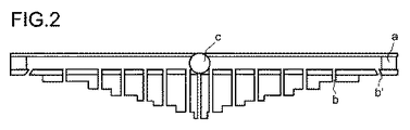
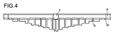
全ての図において、a)は、パイプa)を示し、b)は、直立して配された複数の開口部b)を示し、b’)は、ある角度で設けられた開口部b)を示し、c)は、反応混合物の供給部を示す。全ての図より、開口部b)の長さが外側に行くほど減少していることがわかる。 In all the figures, a) shows a pipe a), b) shows a plurality of openings b) arranged upright , and b ′) shows an opening b) provided at an angle. C) shows the supply part of the reaction mixture. It can be seen from all the figures that the length of the opening b) decreases as it goes outward.
図1は、それぞれの1個のある角度で設けられた開口部b)をもつ対称形アプリケーターを示す。 FIG. 1 shows a symmetrical applicator with an opening b) provided at an angle of one each.
図2は、図1と同じ配列であるが、孔b)が一つ、中央で、反応混合物の供給部の下に設けられているものを示す。 FIG. 2 shows the same arrangement as in FIG. 1, but with one hole b), in the middle, provided below the feed for the reaction mixture.
図3は、片側で1個のある角度で設けられた開口部b)をもち、他の側で2個のある角度で設けられた開口部b)をもつ非対称形アプリケーターを示す。 FIG. 3 shows an asymmetric applicator with an opening b) provided at one angle on one side and an opening b) provided at two angles on the other side.
図4は、それぞれ2個のある角度で設けられた開口部b)をもつ対称形アプリケーターを示す。 FIG. 4 shows a symmetrical applicator with openings b) each provided at two angles.
Claims (15)
この工程で、前記外層が連続的に移動され、
前記液体反応混合物の塗装装置が、少なくとも一本のパイプa)を有し、パイプa)には、前記外層に向けて少なくとも4個の開口部b)が設けられ、更に、反応混合物の供給部c)がパイプa)の中央に設けられ、及び
パイプa)は、前記外層の上側で、外層表面に対して平行に、及び前記外層の移動方向に対して直角方向に設けられている、複合材料の製造方法であって、
前記外層端部上に位置する外側の1〜4個の前記開口部b)が、前記外層に対して垂直方向から、前記外層端部の方向に1〜50°のある角度で設けられていることを特徴とする方法。 Applying the liquid reaction mixture to the outer layer using a liquid reaction mixture coating device;
In this step, the outer layer is continuously moved,
The liquid reaction mixture coating device has at least one pipe a), the pipe a) is provided with at least four openings b) towards the outer layer, and further a reaction mixture supply section c) is provided in the center of the pipe a), and the pipe a) is provided above the outer layer, parallel to the outer layer surface and perpendicular to the moving direction of the outer layer. A method of manufacturing a material,
Outer one to four openings b) located on the outer layer end are provided at an angle of 1 to 50 ° from the direction perpendicular to the outer layer toward the outer layer end. A method characterized by that.
Applications Claiming Priority (3)
| Application Number | Priority Date | Filing Date | Title |
|---|---|---|---|
| DE202011001109.7 | 2011-01-07 | ||
| DE202011001109U DE202011001109U1 (en) | 2011-01-07 | 2011-01-07 | Apparatus for applying liquid reaction mixtures to a cover layer |
| PCT/EP2012/050070 WO2012093129A1 (en) | 2011-01-07 | 2012-01-04 | Method and device for applying liquid reaction mixtures to a cover layer |
Publications (3)
| Publication Number | Publication Date |
|---|---|
| JP2014502920A JP2014502920A (en) | 2014-02-06 |
| JP2014502920A5 JP2014502920A5 (en) | 2016-12-08 |
| JP6057915B2 true JP6057915B2 (en) | 2017-01-11 |
Family
ID=43799294
Family Applications (1)
| Application Number | Title | Priority Date | Filing Date |
|---|---|---|---|
| JP2013547847A Expired - Fee Related JP6057915B2 (en) | 2011-01-07 | 2012-01-04 | Method and apparatus for applying a liquid reaction mixture to a cover layer |
Country Status (17)
| Country | Link |
|---|---|
| US (1) | US20130280538A1 (en) |
| EP (1) | EP2661346B1 (en) |
| JP (1) | JP6057915B2 (en) |
| KR (1) | KR101977124B1 (en) |
| CN (1) | CN103402726B (en) |
| AU (1) | AU2012204871A1 (en) |
| BR (1) | BR112013016688A2 (en) |
| CA (1) | CA2822483A1 (en) |
| DE (1) | DE202011001109U1 (en) |
| DK (1) | DK2661346T3 (en) |
| ES (1) | ES2616456T3 (en) |
| LT (1) | LT2661346T (en) |
| MX (1) | MX2013007482A (en) |
| PL (1) | PL2661346T3 (en) |
| PT (1) | PT2661346T (en) |
| RU (1) | RU2602531C2 (en) |
| WO (1) | WO2012093129A1 (en) |
Families Citing this family (16)
| Publication number | Priority date | Publication date | Assignee | Title |
|---|---|---|---|---|
| EP2614943A1 (en) | 2012-01-16 | 2013-07-17 | Bayer Intellectual Property GmbH | Device for applying a foaming reaction mixture |
| WO2013107739A1 (en) | 2012-01-16 | 2013-07-25 | Bayer Intellectual Property Gmbh | Device for applying a foaming reaction mixture |
| EP2614944A1 (en) | 2012-01-16 | 2013-07-17 | Bayer Intellectual Property GmbH | Device for applying a foaming reaction mixture |
| US9475220B2 (en) | 2013-02-13 | 2016-10-25 | Basf Se | Process for producing composite elements |
| WO2014124824A1 (en) * | 2013-02-13 | 2014-08-21 | Basf Se | Method for producing composite elements |
| RU2706619C2 (en) * | 2014-09-11 | 2019-11-19 | Хантсмэн Интернэшнл Ллс | Method of designing and manufacturing distribution element for applying viscous foaming liquid mixture on laminator |
| KR20180034549A (en) | 2015-07-24 | 2018-04-04 | 바스프 에스이 | Complex Facade with Building |
| DE102016000390A1 (en) * | 2016-01-14 | 2017-07-20 | Dürr Systems Ag | Perforated plate with increased hole spacing in one or both edge regions of a row of nozzles |
| DE102016000356A1 (en) * | 2016-01-14 | 2017-07-20 | Dürr Systems Ag | Perforated plate with reduced diameter in one or both edge regions of a row of nozzles |
| EP3482904A1 (en) | 2017-11-14 | 2019-05-15 | Covestro Deutschland AG | Variable device and method for applying a foamable reaction mixture to a moving cover layer |
| CN109721254B (en) * | 2019-02-21 | 2021-01-01 | 深圳市华星光电技术有限公司 | Nozzle and coating device |
| DE202019101681U1 (en) | 2019-03-25 | 2020-06-26 | Sulzer Mixpac Ag | Distribution head for a distribution device and distribution device |
| DE102019110091A1 (en) | 2019-04-17 | 2020-10-22 | Hennecke Gmbh | Method of manufacturing an insulation panel |
| EP4025420A1 (en) | 2019-09-02 | 2022-07-13 | Dow Global Technologies LLC | Apparatus and method for applying a foaming reaction mixture onto a laminator |
| EP3804939A1 (en) | 2019-10-11 | 2021-04-14 | Covestro Deutschland AG | Method and device for the preparation of foam composite elements |
| WO2023121907A1 (en) | 2021-12-20 | 2023-06-29 | Dow Global Technologies Llc | Apparatus and method for applying a foaming reaction mixture onto a laminator using a diverging nozzle |
Family Cites Families (19)
| Publication number | Priority date | Publication date | Assignee | Title |
|---|---|---|---|---|
| DE2038253A1 (en) * | 1970-07-31 | 1972-02-03 | Shell Internat Res Mij N V | Travelling polyurethane foam sprayer - with several nozzles travelling on one transverse rail |
| DE3045413C2 (en) * | 1980-12-02 | 1983-09-08 | Windmöller & Hölscher, 4540 Lengerich | Process for oxidizing an extruded molten polyethylene film |
| JPH0390645U (en) * | 1989-12-28 | 1991-09-17 | ||
| JP2505333B2 (en) * | 1991-12-11 | 1996-06-05 | 昭和高分子株式会社 | Foam resin coating device |
| JPH0751617A (en) * | 1993-08-11 | 1995-02-28 | Mitsubishi Heavy Ind Ltd | Coating method |
| JPH07246646A (en) * | 1994-03-08 | 1995-09-26 | Hiroshima Kasei Ltd | Manufacture of composite, multiple and irregular-shaped extruded product consisting mainly of thermoplastic elastomer |
| US5564448A (en) * | 1994-12-14 | 1996-10-15 | Eagle-Picher Industries, Inc. | Container washing apparatus and system |
| BR9605946A (en) * | 1995-03-29 | 1997-08-19 | Bosch Gmbh Robert | Perforated disc in particular for injection valves and process for the production of a perforated disc |
| DE19830860A1 (en) * | 1998-07-10 | 2000-01-13 | Gardena Kress & Kastner Gmbh | Method for adjusting the sprinkler image of a sprinkler and sprinkler |
| US6602554B1 (en) * | 2000-01-14 | 2003-08-05 | Illinois Tool Works Inc. | Liquid atomization method and system |
| DE102004044595A1 (en) * | 2004-09-13 | 2006-03-30 | Basf Ag | Process for the production of composite elements based on isocyanate-based foams |
| JP4902983B2 (en) * | 2005-11-01 | 2012-03-21 | ボイス ペ−パ− パテント ゲ−エムベ−ハ− | Coating apparatus and coating method |
| NL1032283C2 (en) | 2006-08-08 | 2008-02-14 | Opstalan B V | Body for applying a viscous mixture to a substrate, as well as a method for manufacturing an insulating element. |
| RU2466019C2 (en) | 2007-02-28 | 2012-11-10 | Басф Се | Method of making composite elements using isocyanate-based foam plastics |
| MX343958B (en) | 2007-12-17 | 2016-11-30 | Basf Se | Methods for producing composite elements based on foams based on isocyanate. |
| US8011602B2 (en) * | 2008-08-15 | 2011-09-06 | Eldon Coppersmith | Oscillating sprinkler that automatically produces a rectangular water distribution pattern |
| CN201243528Y (en) * | 2008-08-22 | 2009-05-27 | 李尧 | Porous type irrigation device |
| EP2233271A1 (en) * | 2009-03-25 | 2010-09-29 | Bayer MaterialScience AG | Sandwich compound element |
| DE202009015838U1 (en) | 2009-11-20 | 2010-02-18 | Basf Se | Apparatus for applying liquid reaction mixtures to a cover layer |
-
2011
- 2011-01-07 DE DE202011001109U patent/DE202011001109U1/en not_active Expired - Lifetime
-
2012
- 2012-01-04 DK DK12701984.2T patent/DK2661346T3/en active
- 2012-01-04 CA CA 2822483 patent/CA2822483A1/en not_active Abandoned
- 2012-01-04 ES ES12701984.2T patent/ES2616456T3/en active Active
- 2012-01-04 PT PT127019842T patent/PT2661346T/en unknown
- 2012-01-04 EP EP12701984.2A patent/EP2661346B1/en active Active
- 2012-01-04 JP JP2013547847A patent/JP6057915B2/en not_active Expired - Fee Related
- 2012-01-04 CN CN201280004647.0A patent/CN103402726B/en active Active
- 2012-01-04 LT LTEP12701984.2T patent/LT2661346T/en unknown
- 2012-01-04 US US13/977,977 patent/US20130280538A1/en not_active Abandoned
- 2012-01-04 PL PL12701984T patent/PL2661346T3/en unknown
- 2012-01-04 AU AU2012204871A patent/AU2012204871A1/en not_active Abandoned
- 2012-01-04 KR KR1020137020508A patent/KR101977124B1/en active IP Right Grant
- 2012-01-04 BR BR112013016688A patent/BR112013016688A2/en not_active IP Right Cessation
- 2012-01-04 RU RU2013136497/05A patent/RU2602531C2/en active
- 2012-01-04 MX MX2013007482A patent/MX2013007482A/en unknown
- 2012-01-04 WO PCT/EP2012/050070 patent/WO2012093129A1/en active Application Filing
Also Published As
| Publication number | Publication date |
|---|---|
| WO2012093129A1 (en) | 2012-07-12 |
| ES2616456T3 (en) | 2017-06-13 |
| RU2602531C2 (en) | 2016-11-20 |
| RU2013136497A (en) | 2015-02-20 |
| CN103402726A (en) | 2013-11-20 |
| KR101977124B1 (en) | 2019-05-10 |
| AU2012204871A1 (en) | 2013-07-11 |
| CN103402726B (en) | 2016-11-16 |
| BR112013016688A2 (en) | 2016-10-04 |
| KR20130133829A (en) | 2013-12-09 |
| US20130280538A1 (en) | 2013-10-24 |
| LT2661346T (en) | 2017-02-10 |
| DK2661346T3 (en) | 2017-02-27 |
| PL2661346T3 (en) | 2017-05-31 |
| PT2661346T (en) | 2017-02-21 |
| JP2014502920A (en) | 2014-02-06 |
| EP2661346B1 (en) | 2016-11-16 |
| DE202011001109U1 (en) | 2011-03-17 |
| EP2661346A1 (en) | 2013-11-13 |
| CA2822483A1 (en) | 2012-07-12 |
| MX2013007482A (en) | 2013-08-15 |
Similar Documents
| Publication | Publication Date | Title |
|---|---|---|
| JP6057915B2 (en) | Method and apparatus for applying a liquid reaction mixture to a cover layer | |
| CA2679240C (en) | Process for producing composite elements based on foams based on isocyanate | |
| CN101077600B (en) | Apparatus and method for producing a sandwich composite | |
| US7540932B2 (en) | Apparatus and process for the production of sandwich composite elements | |
| CA2707500C (en) | Methods for producing composite elements based on foams based on isocyanate | |
| US9724723B2 (en) | Device for applying a foaming reaction mixture | |
| US9242399B2 (en) | Sandwich composite elements | |
| US20110293915A1 (en) | High-pressure device | |
| JP3243571B2 (en) | Method and apparatus for producing foamed synthetic resin plate | |
| JP3760407B2 (en) | Method and apparatus for producing polyurethane foam with strand mat | |
| US9925701B2 (en) | Sandwich composite elements | |
| JP5457800B2 (en) | Insulation panel and method of manufacturing the same | |
| CA2505009C (en) | Method and device for applying a thick reactive coating on a body rotating about an axis | |
| KR101189476B1 (en) | Preparing method of sandwich panel use for fix type foam system and equipment thereof | |
| KR102438331B1 (en) | Foaming application apparatus in continuous building assembly pannel prodution line | |
| NZ733069A (en) | Casting bar for use in manufacture of composite panels | |
| US9381542B2 (en) | Methods for applying a foamable reaction mixture, high pressure device and device for producing sandwich composite elements | |
| WO2023121907A1 (en) | Apparatus and method for applying a foaming reaction mixture onto a laminator using a diverging nozzle | |
| JPS63199618A (en) | Manufacturing device for composite plate of phenolic resin foam | |
| CN114302810A (en) | Multi-layer panel member |
Legal Events
| Date | Code | Title | Description |
|---|---|---|---|
| A621 | Written request for application examination |
Free format text: JAPANESE INTERMEDIATE CODE: A621 Effective date: 20150105 |
|
| A977 | Report on retrieval |
Free format text: JAPANESE INTERMEDIATE CODE: A971007 Effective date: 20150903 |
|
| A131 | Notification of reasons for refusal |
Free format text: JAPANESE INTERMEDIATE CODE: A131 Effective date: 20151013 |
|
| A601 | Written request for extension of time |
Free format text: JAPANESE INTERMEDIATE CODE: A601 Effective date: 20160107 |
|
| A524 | Written submission of copy of amendment under section 19 (pct) |
Free format text: JAPANESE INTERMEDIATE CODE: A524 Effective date: 20160202 |
|
| A131 | Notification of reasons for refusal |
Free format text: JAPANESE INTERMEDIATE CODE: A131 Effective date: 20160726 |
|
| A524 | Written submission of copy of amendment under section 19 (pct) |
Free format text: JAPANESE INTERMEDIATE CODE: A524 Effective date: 20161018 |
|
| TRDD | Decision of grant or rejection written | ||
| A01 | Written decision to grant a patent or to grant a registration (utility model) |
Free format text: JAPANESE INTERMEDIATE CODE: A01 Effective date: 20161115 |
|
| A61 | First payment of annual fees (during grant procedure) |
Free format text: JAPANESE INTERMEDIATE CODE: A61 Effective date: 20161206 |
|
| R150 | Certificate of patent or registration of utility model |
Ref document number: 6057915 Country of ref document: JP Free format text: JAPANESE INTERMEDIATE CODE: R150 |
|
| R250 | Receipt of annual fees |
Free format text: JAPANESE INTERMEDIATE CODE: R250 |
|
| LAPS | Cancellation because of no payment of annual fees |