JP6056172B2 - Data processing apparatus, data processing method, and program - Google Patents
Data processing apparatus, data processing method, and program Download PDFInfo
- Publication number
- JP6056172B2 JP6056172B2 JP2012079580A JP2012079580A JP6056172B2 JP 6056172 B2 JP6056172 B2 JP 6056172B2 JP 2012079580 A JP2012079580 A JP 2012079580A JP 2012079580 A JP2012079580 A JP 2012079580A JP 6056172 B2 JP6056172 B2 JP 6056172B2
- Authority
- JP
- Japan
- Prior art keywords
- waveform
- state
- probability
- unit
- factor
- Prior art date
- Legal status (The legal status is an assumption and is not a legal conclusion. Google has not performed a legal analysis and makes no representation as to the accuracy of the status listed.)
- Active
Links
Images


Description
本技術は、データ処理装置、データ処理方法、及び、プログラムに関し、特に、例えば、家庭にある複数の電気機器それぞれの消費電力等を、容易かつ正確に求めることができるようにするデータ処理装置、データ処理方法、及び、プログラムに関する。 The present technology relates to a data processing device, a data processing method, and a program, and in particular, for example, a data processing device that makes it possible to easily and accurately determine the power consumption of each of a plurality of electrical devices in a home, The present invention relates to a data processing method and a program.
例えば、家庭内等にある家電(家庭用電化製品)等の電気機器の個々の消費電力や消費電流を、家庭内のユーザに提示する、消費電力等のいわゆる「見える化」を実現する方法としては、例えば、各コンセントに、スマートタップを取り付ける方法がある。 For example, as a method of realizing so-called “visualization” of power consumption, etc., presenting individual power consumption and current consumption of electrical equipment such as home appliances (home appliances) in the home to users in the home For example, there is a method of attaching a smart tap to each outlet.
スマートタップは、そのスマートタップが取り付けられたコンセント(に繋がっている家電)で消費されている電力を計測する計測機能と、外部との通信機能とを有する。 The smart tap has a measurement function for measuring the power consumed by an electrical outlet (home appliance connected to) the smart tap and a communication function with the outside.
スマートタップにおいて、計測機能で計測した(消費)電力を、通信機能で、ディスプレイ等に送信し、ディスプレイにおいて、スマートタップからの消費電力を表示することにより、各家電の消費電力の「見える化」を実現することができる。 In the smart tap, the power consumption measured by the measurement function is transmitted to the display, etc. using the communication function, and the power consumption from the smart tap is displayed on the display. Can be realized.
しかしながら、家庭内のすべてのコンセントに、スマートタップを取り付けることは、コストの面で、容易ではない。 However, attaching smart taps to all outlets in the home is not easy in terms of cost.
また、いわゆるビルトインのエアコン(エアコンディショナ)等の、家に備え付けの家電は、コンセントを介さずに、電力線に、直接接続されている場合があり、そのような家電については、スマートタップを用いることは、困難である。 In addition, home appliances such as a so-called built-in air conditioner (air conditioner) may be directly connected to a power line without going through an outlet, and a smart tap is used for such home appliances. That is difficult.
そこで、例えば、家庭等において、配電盤(分電盤)で計測した電流の情報から、その先に繋がっている家庭内の個々の家電の消費電力等を求めるNILM(Non-Intrusive Load Monitoring)と呼ばれる技術が注目されている。 Therefore, for example, in homes, it is called NILM (Non-Intrusive Load Monitoring), which calculates the power consumption of individual household appliances connected to the home based on the current information measured by the switchboard (distribution panel). Technology is drawing attention.
NILMでは、例えば、一箇所で計測した電流等を用いて、そこから先に繋がっている個々の家電(負荷)の消費電力が、個別に計測することなく求められる。 In NILM, for example, using the current measured at one place, the power consumption of each home appliance (load) connected from there can be obtained without separately measuring.
例えば、特許文献1には、一箇所で計測した電流と電圧から、有効電力及び無効電力を算出し、それぞれの変化量をクラスタリングすることで、電気機器の同定を行うNILMの技術が開示されている。
For example,
特許文献1に記載の技術では、家電のオン時とオフ時の有効電力及び無効電力が変化することを利用するために、有効電力及び無効電力の変化点が検出される。このため、変化点の検出に失敗すると、家電を正確に同定することが困難になる。
In the technique described in
また、最近の家電については、稼働状態をオンとオフの2状態で表現することが困難であり、オン時とオフ時の有効電力及び無効電力の変化を利用するだけでは、家電を正確に同定することが困難になっている。 In addition, it is difficult to represent the operating state in two states, on and off, for recent home appliances. By simply using changes in active power and reactive power when on and off, home appliances can be accurately identified. It has become difficult to do.
そこで、例えば、特許文献2及び3には、SVM(Support Vector Machine)等のLMC(Large Margin Classifier)を、家電の識別モデル(判別モデル、Classification)として用いるNILMの技術が記載されている。
Thus, for example,
しかしながら、識別モデルを用いたNILMでは、HMM(Hidden Markov Model)等の生成モデルとは違い、各家電について、既知の学習データを用意し、その学習データを用いた識別モデルの学習を、事前に済ませておく必要がある。 However, in NILM using an identification model, unlike generation models such as HMM (Hidden Markov Model), prepared learning data for each home appliance and learning the identification model using that learning data in advance. It is necessary to finish it.
このため、識別モデルを用いたNILMでは、既知の学習データを用いて識別モデルの学習を行っていない家電については、対応することが困難である。 For this reason, it is difficult for NILM using an identification model to deal with home appliances that have not learned the identification model using known learning data.
そこで、例えば、非特許文献1及び2には、既知の学習データを用いた事前の学習が必要な識別モデルではない、生成モデルであるHMMを用いたNILMの技術が記載されている。
Therefore, for example, Non-Patent
しかしながら、単純なHMMを用いたNILMでは、家電の数が増加すると、HMMの状態の数が膨大となり、実装することが困難となる。 However, in NILM using a simple HMM, as the number of home appliances increases, the number of HMM states becomes enormous, making it difficult to implement.
具体的には、例えば、個々の家電の稼働状態が、オンとオフの2状態である場合に、M個の家電の稼働状態(の組み合わせ)を表現するのに必要なHMMの状態の数は、2M個になり、状態の遷移確率の数は、状態の数の2乗である(2M)2個になる。 Specifically, for example, when the operating state of each home appliance is two states, on and off, the number of HMM states necessary to represent the operating state (combination) of M home appliances is , becomes 2 M pieces, the number of state transition probability is the square of the number of states (2 M) becomes two.
したがって、家庭内の家電の数Mが、最近では多いとはいえない、例えば、20個であったとしても、HMMの状態の数は、220=1,048,576個という膨大な数になり、遷移確率の数は、その2乗の1,099,511,627,776個というテラオーダのさらに膨大な数になる。 Therefore, the number M of household appliances in the home is not very large recently, for example, even if it is 20, the number of HMM states is a huge number of 2 20 = 1,048,576, and the transition probability The number of is the enormous number of the tera order of 1,099,511,627,776 of the square.
現在においては、稼働状態が、オンとオフの2状態だけではない家電、すなわち、モードや設定等によって消費電力(電流)が変動するエアコン等の家電(変動負荷家電)のような電気機器の個々の消費電力等を、容易かつ正確に求めることができるNILMの技術の提案が要請されている。 At present, individual appliances such as home appliances (power-changing home appliances) such as air conditioners whose power consumption (current) fluctuates depending on modes and settings, etc. There is a demand for a proposal for NILM technology that can easily and accurately determine the power consumption and other factors.
本技術は、このような状況に鑑みてなされたものであり、電気機器の個々の消費電力等を、容易かつ正確に求めることができるようにするものである。 The present technology has been made in view of such a situation, and makes it possible to easily and accurately obtain individual power consumption and the like of an electric device.
本技術の一側面のデータ処理装置、又は、プログラムは、複数の話者が発話した音声が重畳された音声信号の総和を表すデータを用いて、前記話者の発話状態を求める状態推定を行う状態推定部と、前記話者に固有の音声に関する固有波形を求める波形分離学習を、前記状態推定部による前記状態推定を用いて、前記音声が取り得る周波数帯域内の周波数成分に制限して行う波形分離学習部とを備えるデータ処理装置、又は、データ処理装置として、コンピュータを機能させるためのプログラム。 A data processing device or program according to one aspect of the present technology performs state estimation for obtaining a speech state of the speaker using data representing a sum of speech signals superimposed with speech uttered by a plurality of speakers. The state estimation unit and waveform separation learning for obtaining a specific waveform related to the voice unique to the speaker are performed by using the state estimation by the state estimation unit and limiting frequency components within a frequency band that the voice can take. A program for causing a computer to function as a data processing device or a data processing device including a waveform separation learning unit.
本技術の一側面のデータ処理方法は、複数の話者が発話した音声が重畳された音声信号の総和を表すデータを用いて、前記話者の発話状態を求める状態推定を行い、前記話者に固有の音声に関する固有波形を求める波形分離学習を、前記状態推定を用いて、前記音声が取り得る周波数帯域内の周波数成分に制限して行うステップを含むデータ処理方法である。 A data processing method according to one aspect of the present technology performs state estimation for obtaining a speech state of the speaker by using data representing a sum of speech signals superimposed with speech uttered by a plurality of speakers, and the speaker A data processing method including a step of performing waveform separation learning for obtaining a specific waveform related to a sound specific to a voice by using the state estimation to limit frequency components within a frequency band that can be taken by the voice .
本技術の一側面においては、複数の話者が発話した音声が重畳された音声信号の総和を表すデータを用いて、前記話者の発話状態を求める状態推定が行われ、前記話者に固有の音声に関する固有波形を求める波形分離学習が、前記状態推定を用いて、前記音声が取り得る周波数帯域内の周波数成分に制限して行われる。 In one aspect of the present technology, state estimation is performed to determine the utterance state of the speaker using data representing the sum of speech signals superimposed with speech uttered by a plurality of speakers. Waveform separation learning for obtaining a specific waveform related to the voice is performed by limiting the frequency components in the frequency band that the voice can take using the state estimation .
なお、データ処理装置は、独立した装置であっても良いし、1つの装置を構成している内部ブロックであっても良い。 Note that the data processing device may be an independent device or an internal block constituting one device.
また、プログラムは、伝送媒体を介して伝送することにより、又は、記録媒体に記録して、提供することができる。 The program can be provided by being transmitted via a transmission medium or by being recorded on a recording medium.
本技術の一側面によれば、電気機器の個々の消費電力等を、容易かつ正確に求めることができる。 According to one aspect of the present technology, it is possible to easily and accurately obtain individual power consumption of an electrical device.
[本技術の概要] [Outline of this technology]
図1は、本技術のデータ処理装置を適用した監視システムの一実施の形態の概要を説明する図である。 FIG. 1 is a diagram illustrating an overview of an embodiment of a monitoring system to which a data processing device of the present technology is applied.
各家庭において、電力会社から提供される電力は、配電盤(分電盤)に引き込まれ、配電盤から、家庭内の(コンセント等に接続された)家電等の電気機器に供給される。 In each household, electric power provided by an electric power company is drawn into a switchboard (distribution panel), and is supplied from the switchboard to electrical equipment such as home appliances (connected to an outlet or the like) in the home.
本技術を適用した監視システムは、配電盤の、家庭内に電力を供給している、いわば根元等の1箇所において、家庭内の1以上の家電で消費されている電流の総和を計測し、その電流の総和の系列(電流波形系列)から、家庭内の、例えば、エアコンや掃除機等の個々の家電で消費されている電力(電流)を分離する家電分離を行う。 The monitoring system to which this technology is applied measures the sum of the current consumed by one or more home appliances in the home at one location such as the root of the switchboard that supplies power to the home. The household appliance separation which isolate | separates the electric power (electric current) consumed by each household appliances, such as an air conditioner and a vacuum cleaner in a household, is performed from the series (current waveform series) of the sum of currents.
なお、監視システムに入力する入力データとしては、各家電で消費されている電流の総和そのものの他、各家電で消費されている電流の総和に関する総和データを採用することができる。 As input data to be input to the monitoring system, total data relating to the sum of currents consumed by each home appliance can be adopted in addition to the sum of currents consumed by each home appliance itself.
総和データとしては、加算が成立する値の総和を採用することができる。具体的には、総和データとしては、各家電で消費されている電流の総和そのものの他、例えば、各家電で消費されている電力の総和や、各家電で消費されている電流の波形をFFT(Fast Fourier Transform)等することによって得られる周波数成分の総和等を採用することができる。 As the summation data, the summation of values for which addition is established can be employed. Specifically, as the total data, in addition to the total current consumed by each home appliance itself, for example, the sum of the power consumed by each home appliance and the waveform of the current consumed by each home appliance The sum total of frequency components obtained by (Fast Fourier Transform) or the like can be adopted.
また、家電分離では、総和データから、個々の家電で消費されている電力の他、個々の家電で消費されている電流に関する情報を分離することができる。具体的には、家電分離では、総和データから、例えば、個々の家電で消費されている電流や、その周波数成分を分離することができる。 Moreover, in household appliance isolation | separation, the information regarding the electric current consumed by each household appliance other than the electric power consumed by each household appliance can be isolate | separated from total data. Specifically, in home appliance separation, for example, current consumed by individual home appliances and frequency components thereof can be separated from the total data.
以下の説明では、総和データとして、例えば、各家電で消費されている電流の総和を採用するとともに、家電分離において、例えば、総和データとしての電流の総和の波形から、個々の家電で消費されている電流の波形を分離することとする。 In the following description, for example, the sum of current consumed by each home appliance is adopted as the sum data, and in the home appliance separation, for example, from the waveform of the sum of current as sum data, consumed by each home appliance. The current waveform is separated.
図2は、家電分離で行われる波形分離学習の概要を説明する図である。 FIG. 2 is a diagram for explaining an outline of waveform separation learning performed in home appliance separation.
波形分離学習では、各時刻tの総和データとしての電流波形Ytが、各家電#mで消費されている電流の電流波形W(m)の加算値(総和)であるとして、電流波形Ytから、個々の家電#mで消費されている電流波形W(m)が求められる。 As the waveform separation learning, the current waveform Y t as the sum data for each time t is the sum of the current waveform W (m) of the current being consumed by each home #m (sum), the current waveform Y t from the current waveform W being consumed by the individual consumer electronics #m (m) is obtained.
図2では、家庭内に、5個の家電#1ないし#5があり、その5個の家電#1ないし#5のうちの、家電#1,#2,#4、及び、#5がオン状態(電力を消費する状態)になっており、家電#3がオフ状態(電力を消費しない状態)になっている。
In FIG. 2, there are five
そのため、図2では、総和データとしての電流波形Ytが、家電#1,#2,#4、及び、#5それぞれの消費電流W(1),W(2),W(4)、及び、W(5)の加算値(総和)になっている。
Therefore, in FIG. 2, the current waveform Y t as the sum data is the current consumption W (1) , W (2) , W (4) , and # 5 of the
[本技術を適用した監視システムの第1実施の形態] [First embodiment of a monitoring system to which the present technology is applied]
図3は、本技術を適用した監視システムの第1実施の形態の構成例を示すブロックである。 FIG. 3 is a block diagram illustrating a configuration example of the first embodiment of the monitoring system to which the present technology is applied.
図3において、監視システムは、データ取得部11、状態推定部12、モデル記憶部13、モデル学習部14、ラベル取得部15、及び、データ出力部16を有する。
In FIG. 3, the monitoring system includes a
データ取得部11は、総和データとしての電流波形Yの時系列(電流時系列)、及び、その電流波形Yに対応する電圧の波形(電圧波形)Vの時系列(電圧時系列)を取得し、状態推定部12、モデル学習部14、及び、データ出力部16に供給する。
The
すなわち、データ取得部11は、例えば、電流と電圧を計測する計測器(センサ)で構成される。
That is, the
データ取得部11は、例えば、配電盤等において、監視システムが設置されている家庭内の各家電で消費されている電流の総和としての電流波形Yを計測するとともに、対応する電圧波形Vを計測し、状態推定部12、モデル学習部14、及び、データ出力部16に供給する。
The
状態推定部12は、データ取得部11からの電流波形Yと、モデル記憶部13に記憶された、監視システムが設置されている家庭内の家電全体のモデルである全体モデル(のモデルパラメータ)φとを用いて、各家電の稼働状態を推定する状態推定を行う。そして、状態推定部12は、状態推定の推定結果としての各家電の稼働状態Γを、モデル学習部14、ラベル取得部15、及び、データ出力部16に供給する。
The state estimation unit 12 includes a current waveform Y from the
すなわち、図3において、状態推定部12は、評価部21、及び、推定部22を有する。
That is, in FIG. 3, the state estimation unit 12 includes an
評価部21は、モデル記憶部13に記憶された全体モデルφを構成する複数の家電モデル#1ないし#Mそれぞれの状態の各組み合わせにおいて、データ取得部11から(状態推定部12に)供給される電流波形Yが観測される程度を評価した評価値Eを求め、推定部22に供給する。
The
推定部22は、評価部21から供給される評価値Eを用い、モデル記憶部13に記憶された全体モデルφを構成する複数の家電モデル#1ないし#Mそれぞれにおいている状態、すなわち、家電モデル#mが表す家電(家電モデル#mによってモデル化された家電)の稼働状態Γを推定し、モデル学習部14、ラベル取得部15、及び、データ出力部16に供給する。
The
モデル記憶部13は、複数の家電全体のモデルである全体モデル(のモデルパラメータ)φを記憶する。
The
全体モデルφは、複数であるM個の、家電の(消費電流を表現する)モデルである家電モデル#1ないし#Mから構成される。
The overall model φ is composed of a plurality of M home
全体モデルのパラメータφには、家電モデル#mが表す家電の稼働状態ごとの消費電流を表す電流波形パラメータが含まれる。 The overall model parameter φ includes a current waveform parameter that represents current consumption for each operating state of the home appliance represented by home appliance model #m.
全体モデルのパラメータφには、その他、例えば、家電モデル#mが表す家電の稼働状態の遷移(変動)を表す状態変動パラメータ、家電モデル#mが表す家電の稼働状態の初期状態を表す初期状態パラメータ、及び、全体モデルにおいて観測(生成)される電流波形Yの観測値の分散に関する分散パラメータを含めることができる。 The overall model parameter φ includes, for example, a state variation parameter that represents the transition (variation) of the operating state of the home appliance represented by the home appliance model #m, and an initial state that represents the initial state of the home appliance operating state represented by the home appliance model #m. The parameter and a dispersion parameter related to the dispersion of the observed value of the current waveform Y observed (generated) in the overall model can be included.
モデル記憶部13に記憶された全体モデルのモデルパラメータφは、状態推定部12の評価部21と推定部22、ラベル取得部15、及び、データ出力部16で参照され、モデル学習部14の後述する波形分離学習部31、分散学習部32、及び、状態変動学習部33によって更新される。
The model parameters φ of the entire model stored in the
モデル学習部14は、データ取得部11から供給される電流波形Yと、状態推定部12(の推定部22)から供給される状態推定の推定結果(各家電の稼働状態)Γとを用いて、モデル記憶部13に記憶された全体モデルのモデルパラメータφを更新するモデル学習を行う。
The
すなわち、図3において、モデル学習部14は、波形分離学習部31、分散学習部32、及び、状態変動学習部33を有する。
That is, in FIG. 3, the
波形分離学習部31は、データ取得部11から(モデル学習部14に)供給される電流波形Yと、状態推定部12(の推定部22)から供給される各家電の稼働状態Γとを用いて、モデルパラメータφとしての電流波形パラメータを求める(更新する)波形分離学習を行い、その波形分離学習によって得られる電流波形パラメータによって、モデル記憶部13に記憶された電流波形パラメータを更新する。
The waveform
分散学習部32は、データ取得部11から(モデル学習部14に)供給される電流波形Yと、状態推定部12(の推定部22)から供給される各家電の稼働状態Γとを用いて、モデルパラメータφとしての分散パラメータを求める(更新する)分散学習を行い、その分散学習によって得られる分散パラメータによって、モデル記憶部13に記憶された分散パラメータを更新する。
The distributed
状態変動学習部33は、状態推定部12(の推定部22)から供給される各家電の稼働状態Γを用いて、モデルパラメータφとしての初期状態パラメータ、及び、状態変動パラメータを求める(更新する)状態変動学習を行い、その状態変動学習によって得られる初期状態パラメータ、及び、状態変動パラメータによって、モデル記憶部13に記憶された初期状態パラメータ、及び、状態変動パラメータをそれぞれ更新する。
The state
ラベル取得部15は、状態推定部12(の推定部22)から供給される各家電の稼働状態Γ、モデル記憶部13に記憶された全体モデルφ、及び、データ出力部16で得られる、各家電モデル#mが表す家電の消費電力U(m)等を、必要に応じて用いて、各家電モデル#mが表す家電を識別するための家電ラベルL(m)を取得し、データ出力部16に供給する。
The
データ出力部16は、データ取得部11から供給される電圧波形V、状態推定部12(の推定部22)から供給される各家電の稼働状態Γφ、及び、モデル記憶部13に記憶された全体モデルを用いて、各家電モデル#mが表す家電の消費電力U(m)を求め、図示せぬディスプレイに表示すること等によって、ユーザに提示する。
The data output unit 16 includes the voltage waveform V supplied from the
なお、データ出力部16において、各家電モデル#mが表す家電の消費電力U(m)は、ラベル取得部15から供給される家電ラベルL(m)とともに、ユーザに提示することができる。
In the data output unit 16, the power consumption U (m) of the home appliance represented by each home appliance model #m can be presented to the user together with the home appliance label L (m) supplied from the
以上のように構成される監視システムにおいて、モデル記憶部13に記憶される全体モデルとしては、例えば、FHMM(Factorial Hidden Markov Model)を採用することができる。
In the monitoring system configured as described above, for example, an FHMM (Factorial Hidden Markov Model) can be adopted as the overall model stored in the
図4は、FHMMを説明する図である。 FIG. 4 is a diagram for explaining the FHMM.
すなわち、図4Aは、通常のHMMのグラフィカルモデルを示しており、図4Bは、FHMMのグラフィカルモデルを示している。 That is, FIG. 4A shows a graphical model of a normal HMM, and FIG. 4B shows a graphical model of an FHMM.
通常のHMMでは、時刻tに、その時刻tにいる1つの状態Stにおいて、1つの観測値Ytが観測される。 In a typical HMM, at time t, in one state S t being in that time t, one observed value Y t is observed.
一方、FHMMでは、時刻tに、その時刻tにいる複数の状態S(1) t,S(2) t,・・・,S(M) tの組み合わせにおいて、1つの観測値Ytが観測される。 On the other hand, in FHMM, at time t, one observation value Y t is observed in a combination of a plurality of states S (1) t , S (2) t , ..., S (M) t at that time t. Is done.
FHMMは、Zoubin Ghahramaniらが提案した確率生成モデルであり、その詳細については、例えば、Zoubin Ghahramani, and Michael I. Jordan, Factorial Hidden Markov Models’, Machine Learning Volume 29, Issue 2-3 ,Nov./Dec. 1997(以下、文献Aともいう)に記載されている。 FHMM is a probability generation model proposed by Zoubin Ghahramani et al. For details, see, for example, Zoubin Ghahramani, and Michael I. Jordan, Factorial Hidden Markov Models', Machine Learning Volume 29, Issue 2-3, Nov./ Dec. 1997 (hereinafter also referred to as Document A).
図5は、FHMMによる家電分離の定式化の概要を説明する図である。 FIG. 5 is a diagram for explaining the outline of the formulation of home appliance separation by FHMM.
ここで、FHMMは、複数のHMMを有する構成になっている。FHMMが有する各HMMを、ファクタともいい、m番目のファクタを、ファクタ#mとも記載する。 Here, the FHMM has a configuration having a plurality of HMMs. Each HMM included in the FHMM is also referred to as a factor, and the m-th factor is also described as factor #m.
FHMMにおいて、時刻tにいる複数の状態S(1) tないしS(M) tの組み合わせとは、時刻tにいる各ファクタ#mの状態の組み合わせ(ファクタ#1の状態と、ファクタ#2の状態と、・・・、ファクタ#Mの状態とのセット)である。
In the FHMM, a combination of a plurality of states S (1) t to S (M) t at time t is a combination of the states of factor #m at time t (
図5は、ファクタの数Mが3のFHMMを示している。 FIG. 5 shows an FHMM having a factor number M of 3.
家電分離においては、例えば、1つのファクタが1つの家電に対応する(1つのファクタと1つの家電とを対応させる)。図5では、ファクタ#mが、家電#mに対応している。 In household appliance separation, for example, one factor corresponds to one household appliance (one factor corresponds to one household appliance). In FIG. 5, factor #m corresponds to home appliance #m.
FHMMにおいて、ファクタを構成する状態の数は、ファクタごとに任意であるが、図5では、3つのファクタ#1,#2,#3の状態の数は、いずれも、4個になっている。
In the FHMM, the number of states constituting the factor is arbitrary for each factor, but in FIG. 5, the number of states of the three
図5では、時刻t=t0において、ファクタ#1は、4つの状態#11,#12,#13,#14のうちの、状態#14(太線の丸印で示す)になっており(いて)、ファクタ#2は、4つの状態#21,#22,#23,#24のうちの、状態#21(太線の丸印で示す)になっている。また、時刻t=t0において、ファクタ#3は、4つの状態#31,#32,#33,#34のうちの、状態#33(太線の丸印で示す)になっている。
In FIG. 5, at time t = t0, the
家電分離においては、ファクタ#mの状態は、そのファクタ#mが対応する家電#mの稼働状態に対応する。 In home appliance separation, the state of factor #m corresponds to the operating state of home appliance #m to which factor #m corresponds.
例えば、家電#1に対応するファクタ#1において、状態#11は、家電#1のオフ状態に対応し、状態#14は、家電#1の、いわゆる通常モードのオン状態に対応する。また、例えば、家電#1に対応するファクタ#1において、状態#12は、家電#1の、いわゆるスリープモードのオン状態に対応し、状態#13は、家電#1の、いわゆる省エネモードのオン状態に対応する。
For example, in
FHMMにおいて、ファクタ#mの状態#miでは、各ファクタの状態ごとに固有の波形である固有波形W(m) #miが観測(生成)される。 In the FHMM, in the state #mi of the factor #m, a unique waveform W (m) #mi, which is a unique waveform for each state of each factor, is observed (generated).
図5において、ファクタ#1では、時刻t=t0にいる状態#14において、固有波形W(1) #14が観測され、ファクタ#2では、時刻t=t0にいる状態#21において、固有波形W(2) #21が観測される。さらに、ファクタ#3では、時刻t=t0にいる状態#33において、固有波形W(3) #33が観測される。
In FIG. 5, the characteristic waveform W (1) # 14 is observed in the
FHMMでは、各ファクタにいる状態において観測される固有波形を合成した合成波形が、FHMMにおいて観測される観測値として生成される。 In the FHMM, a combined waveform obtained by synthesizing the eigen waveform observed in each factor is generated as an observed value observed in the FHMM.
ここで、固有波形の合成としては、例えば、固有波形の総和(加算)を採用することができる。その他、固有波形の合成としては、例えば、固有波形の重み付け加算や、固有波形の論理和(固有波形の値が0と1の場合)等を採用することができるが、家電分離では、固有波形の総和が採用される。 Here, as the synthesis of the characteristic waveforms, for example, the total sum (addition) of the characteristic waveforms can be employed. In addition, for the synthesis of eigen waveforms, for example, weighted addition of eigen waveforms or logical sum of eigen waveforms (when eigen waveform values are 0 and 1) can be used. The sum of is adopted.
FHMMの学習では、FHMMにおいて、各時刻t=・・・,t0,t1,・・・の総和データとしての電流波形・・・,Yt0,Yt0+1,・・・が観測されるように、FHMMのモデルパラメータが求められる(更新される)。 In the FHMM learning, the current waveform as the sum data at each time t = ..., t0, t1,..., Y t0 , Y t0 + 1 ,. In addition, FHMM model parameters are obtained (updated).
モデル記憶部13(図3)に記憶される全体モデルφとして、以上のようなFHMMを採用する場合、全体モデルφを構成する家電モデル#mは、ファクタ#mに相当する。 When the above FHMM is adopted as the overall model φ stored in the model storage unit 13 (FIG. 3), the home appliance model #m constituting the overall model φ corresponds to a factor #m.
なお、FHMMのファクタの数Mとしては、家庭内に存在すると想定される家電の最大数よりもマージンとしての所定数だけ大きい値が採用される。 Note that as the factor M of the FHMM, a value larger by a predetermined number as a margin than the maximum number of home appliances assumed to be present in the home is adopted.
また、全体モデルφとしてのFHMMとしては、各ファクタが3以上の状態を有するFHMMが採用される。 In addition, as the FHMM as the overall model φ, an FHMM having a state where each factor is 3 or more is employed.
ファクタが2状態しか有しない場合には、そのファクタに対応する家電の稼働状態として、例えば、オフ状態とオン状態との2状態しか表現することができず、モードや設定等によって消費電力(電流)が変動するエアコン等の家電(以下、変動負荷家電ともいう)について、正確な消費電力等を求めることが困難になるからである。 When the factor has only two states, the home appliance operating state corresponding to the factor can express only two states, for example, an off state and an on state. This is because it is difficult to obtain accurate power consumption for home appliances such as air conditioners (hereinafter also referred to as fluctuating load home appliances) that fluctuate.
すなわち、全体モデルφとしてのFHMMとして、各ファクタが3以上の状態を有するFHMMを採用することにより、変動負荷家電について、正確な消費電力等を求めることが可能となる。 That is, by adopting an FHMM having a factor of 3 or more as the FHMM as the overall model φ, it is possible to obtain accurate power consumption and the like for the variable load home appliance.
全体モデルφとして、FHMMを採用する場合、FHMMにおいて観測される電流波形Ytの系列と、各ファクタ#mの状態S(m) tの組み合わせStの系列との同時分布P({St,Yt})は、マルコフ性を仮定することにより、式(1)で計算される。 Overall model phi, when adopting the FHMM, simultaneous distribution of the sequence of the current waveform Y t observed in FHMM, the combination S t a sequence of states S (m) t of each factor #m P ({S t , Y t }) is calculated by equation (1) by assuming Markov property.

ここで、同時分布P({St,Yt})は、時刻tにおいて、各ファクタ#mの状態S(m) tの組み合わせ(M個のファクタそれぞれの状態の組み合わせ)Stにおいて、電流波形Ytが観測される確率を表す。 Here, the joint distribution P ({S t, Y t }) at time t, at each factor state S (m) (combination of the M factors for each state) a combination of t of #m S t, the current This represents the probability that the waveform Y t is observed.
P(S1)は、最初の時刻t=1において、各ファクタ#mの状態S(m) 1の組み合わせS1にいる初期状態確率を表す。 P (S 1 ) represents the initial state probability of being in the combination S 1 of the state S (m) 1 of each factor #m at the first time t = 1.
P(St|St-1)は、時刻t-1に、状態の組み合わせSt-1にいて、時刻tに、状態の組み合わせStに遷移する遷移確率を表す。 P (S t | S t- 1) is the time t-1, the state of the combination S t-1 Niite, at time t, represents the transition probability of transition to a combination of state S t.
P(Yt|St)は、時刻tに、状態の組み合わせStにおいて、電流波形Ytが観測される観測確率を表す。 P (Y t | S t) is the time t, the combination S t state represents the observation probability of the current waveform Y t is observed.
時刻tにおける状態の組み合わせStは、M個のファクタ#1ないし#Mそれぞれの、時刻tにおける状態S(1) t,S(2) t,・・・,S(M) tの組み合わせであり、式St={S(1) t,S(2) t,・・・,S(M) t}で表現される。
State combinations S t of at time t, the M pieces of
なお、家電#mの稼働状態は、他の家電#m'とは独立に変動すると仮定し、ファクタ#mの状態S(m) tは、他のファクタ#m'の状態S(m') tとは独立に遷移することとする。 Note that the operating state of home appliance #m is assumed to fluctuate independently from other home appliances #m ′, and the state S (m) t of factor #m is the state S (m ′) of other factor #m ′. Transitions are independent of t .
また、FHMMのファクタ#mとしてのHMMの状態の数K(m)としては、他のファクタ#m'としてのHMMの状態の数K(m')とは独立な数を採用することができる。但し、ここでは、説明を簡単にするため、ファクタ#1ないし#Mの状態の数K(1)ないしK(M)は、式K(1)=K(2)=・・・=K(M)=Kで表される通り、同一の数Kであることとする。
In addition, as the number K (m) of the HMM states as the factor #m of the FHMM, a number independent of the number K (m ′) of the HMM states as the other factor #m ′ can be adopted. . However, here, for simplicity of explanation, the numbers K (1) to K (M) of the states of
FHMMにおいて、式(1)の同時分布P({St,Yt})の計算に必要な初期状態確率P(S1)、遷移確率P(St|St-1)、及び、観測確率P(Yt|St)は、以下のように計算することができる。 In FHMM, initial state probability P (S 1 ), transition probability P (S t | S t-1 ), and observation necessary for calculating simultaneous distribution P ({S t , Y t }) of equation (1) The probability P (Y t | S t ) can be calculated as follows.
すなわち、初期状態確率P(S1)は、式(2)に従って計算することができる。 That is, the initial state probability P (S 1 ) can be calculated according to the equation (2).
ここで、P(S(m) 1)は、ファクタ#mの状態S(m) 1が、最初の時刻t=1にいる状態(初期状態)である初期状態確率を表す。 Here, P (S (m) 1 ) represents the initial state probability that the state S (m) 1 of the factor #m is the first state (initial state) at time t = 1.
初期状態確率P(S(m) 1)は、例えば、ファクタ#mのk番目(k=1,2,・・・,K)の状態の初期状態確率を、k行目のコンポーネントとするK行の列ベクトル(K行1列の行列)である。 The initial state probability P (S (m) 1 ) is, for example, K with the initial state probability of the k-th (k = 1, 2,..., K) state of factor #m as the k-th row component. A column vector of rows (a matrix of K rows and 1 column).
遷移確率P(St|St-1)は、式(3)に従って計算することができる。 The transition probability P (S t | S t−1 ) can be calculated according to equation (3).
ここで、P(S(m) t|S(m) t-1)は、ファクタ#mにおいて、時刻t-1に状態S(m) t-1にいて、時刻tに状態S(m) tに遷移する遷移確率を表す。 Here, P (S (m) t | S (m) t-1) , in factor #m, the time t-1 to the state S (m) t-1 Niite, time t to the state S (m) This represents the transition probability of transition to t .
遷移確率P(S(m) t|S(m) t-1)は、例えば、ファクタ#mのk番目の状態#kから、k'番目(k'=1,2,・・・,K)の状態#k'に遷移する遷移確率を、k行k'列目のコンポーネントとするK行K列の行列(正方行列)である。 The transition probability P (S (m) t | S (m) t−1 ) is, for example, k′th (k ′ = 1, 2,..., K from the kth state #k of the factor #m. ) In the K-th row and K-th column as a component (square matrix).
観測確率P(Yt|St)は、式(4)に従って計算することができる。 The observation probability P (Y t | S t ) can be calculated according to equation (4).
ここで、ダッシュ(’)は転置を表し、上付きの−1は、逆数(逆行列)を表す。また、|C|は、Cの絶対値(行列式)(determinant演算)を表す。 Here, a dash (') represents transposition, and a superscript -1 represents an inverse (inverse matrix). | C | represents the absolute value (determinant) of C (determinant operation).
また、Dは、観測値Ytの次元を表す。 Also, D is represents the dimension of the observed value Y t.
例えば、図3のデータ取得部11は、電圧が、負の値から正の値に変化するときのゼロ交差のあるタイミングを、電流の位相が0になっているタイミングとして、所定のサンプリング間隔で、1周期分(日本では、1/50又は1/60秒)の電流をサンプリングし、そのサンプリング値をコンポーネントとする列ベクトルを、1時刻分の電流波形Ytとして出力する。
For example, the
データ取得部11が1周期分の電流をサンプリングするサンプリングの回数がD回であるとすると、電流波形Ytは、D行の列ベクトルである。
Assuming that the number of times that the
式(4)の観測確率P(Yt|St)によれば、観測値Ytは、平均値(平均ベクトル)がμtで、分散(共分散行列)がCの正規分布に従う。 According to the observation probability P (Y t | S t ) in Expression (4), the observed value Y t follows a normal distribution with an average value (average vector) of μ t and a variance (covariance matrix) of C.
平均値μtは、例えば、電流波形Ytと同様のD行の列ベクトルであり、分散Cは、例えば、D行D列の行列(対角成分が分散の行列)である。 Mean value mu t is, for example, a column vector D line similar to the current waveform Y t, dispersion C, for example, a D line D columns of the matrix (a matrix of diagonal components dispersed).
平均値μtは、図5で説明した固有波形W(m)を用い、式(5)で表される。 Mean value mu t uses a unique waveform W (m) described in FIG. 5, represented by the formula (5).
ここで、ファクタ#mの状態#kの固有波形を、W(m) kと表すこととすると、ファクタ#mの状態#kの固有波形W(m) kは、例えば、電流波形Ytと同様のD行の列ベクトルである。 Here, if the eigen waveform of state #k with factor #m is expressed as W (m) k , eigen waveform W (m) k of state #k with factor #m is, for example, current waveform Y t and It is a column vector of similar D rows.
また、固有波形W(m)は、ファクタ#mの各状態#1,#2,・・・,#Kの固有波形W(m) 1,W(m) 2,・・・,W(m) Kの集まりであり、ファクタ#mの状態#kの固有波形W(m) kである列ベクトルを、k列目のコンポーネントとするD行K列の行列である。 The characteristic waveform W (m) is the characteristic waveform W (m) 1 , W (m) 2 , ..., W (m ) A matrix of D rows and K columns having a column vector that is a collection of K and a natural waveform W (m) k of state #k with factor #m as a component of the kth column.
さらに、S*(m) tは、時刻tにいるファクタ#mの状態を表し、以下、S*(m) tを、時刻tのファクタ#mの現在状態ともいう。時刻tのファクタ#mの現在状態S*(m) tは、例えば、式(6)に示すように、K行のうちの1行のみのコンポーネントが0で、他の行のコンポーネントが0のK行の列ベクトルである。 Further, S * (m) t represents the state of factor #m at time t, and hereinafter, S * (m) t is also referred to as the current state of factor #m at time t. Current state S * (m) t factors #m of time t, for example, as shown in equation (6), in component 0 of only one row of the K line, the other line component is 0 It is a column vector of K rows.
時刻tにいるファクタ#mの状態が、状態#kである場合、時刻tのファクタ#mの現在状態S*(m) tとしてのK行の列ベクトルS*(m) tは、k行目のコンポーネントだけが1とされ、他のコンポーネントは0とされる。 If the state of factor #m at time t is state #k, the column vector S * (m) t of K rows as the current state S * (m) t of factor #m at time t is k rows Only the eye component is set to 1, and the other components are set to 0.
式(5)によれば、時刻tにいる各ファクタ#mの状態#kの固有波形W(m) kの総和が、時刻tの電流波形Ytの平均値μtとして求められる。 According to the equation (5), the total sum of the characteristic waveforms W (m) k of the state #k of each factor #m at time t is obtained as the average value μ t of the current waveform Y t at time t.
FHMMのモデルパラメータφは、式(2)の初期状態確率P(S(m) 1)、式(3)の遷移確率P(S(m) t|S(m) t-1)、式(4)の分散C、及び、式(5)の固有波形W(m)(=W(m) 1,W(m) 2,・・・,W(m) K)であり、図3のモデル学習部14では、これらのFHMMのモデルパラメータφが求められる。
The model parameters φ of the FHMM are the initial state probability P (S (m) 1 ) in equation (2), the transition probability P (S (m) t | S (m) t-1 ) in equation ( 3 ), dispersion C 4), and a formula (5 unique waveform W in) (m) (= W ( m) 1, W (m) 2, ···, W (m) K), the model of Figure 3 The
すなわち、波形分離学習部31は、波形分離学習によって、固有波形W(m)を、電流波形パラメータとして求める。分散学習部32では、分散学習によって、分散Cを、分散パラメータとして求める。状態変動学習部33は、状態変動学習によって、初期状態確率P(S(m) 1)、及び、遷移確率P(S(m) t|S(m) t-1)を、それぞれ、初期状態パラメータ、及び、状態変動パラメータとして求める。
That is, the waveform
ここで、前述したように、例えば、個々の家電の稼働状態が、オンとオフの2状態であっても、通常のHMMによって、20個の家電の稼働状態(の組み合わせ)を表現する場合には、HMMの状態の数は、220=1,048,576個になり、遷移確率の数は、その2乗の1,099,511,627,776個になる。 Here, as described above, for example, even when the operating state of each home appliance is two states of ON and OFF, when the operating state (combination) of 20 home appliances is expressed by a normal HMM The number of HMM states is 2 20 = 1,048,576, and the number of transition probabilities is 1,099,511,627,776 of the square.
一方、FHMMによれば、稼働状態がオンとオフの2状態しかないM個の家電は、各ファクタが2状態の、M個のファクタによって表現することができる。したがって、各ファクタにおいて、状態の数は、2個であり、遷移確率の数は、その2乗の4個であるから、FHMMによって、M=20個の家電(ファクタ)の稼働状態を表現する場合には、FHMMの状態の数(総数)は、40=2×20個という少ない数で済み、遷移確率の数も、80=4×20個という少ない数で済む。 On the other hand, according to FHMM, M home appliances that have only two states of operation on and off can be represented by M factors each having two states. Therefore, in each factor, the number of states is two, and the number of transition probabilities is four of the squares. Therefore, the operating state of M = 20 home appliances (factors) is expressed by FHMM. In this case, the number of FHMM states (total number) may be as small as 40 = 2 × 20, and the number of transition probabilities may be as small as 80 = 4 × 20.
FHMMの学習、すなわち、FHMMのモデルパラメータφとしての初期状態確率P(S(m) 1)、遷移確率P(S(m) t|S(m) t-1)、分散C、及び、固有波形W(m)の更新は、例えば、文献Aに記載されているように、EM(Expectation-Maximization)アルゴリズムに従って行うことができる。 FHMM learning, that is, initial state probability P (S (m) 1 ), transition probability P (S (m) t | S (m) t-1 ), variance C, and eigenvalue as model parameter φ of FHMM The update of the waveform W (m) can be performed according to an EM (Expectation-Maximization) algorithm as described in Document A, for example.
EMアルゴリズムによるFHMMの学習では、式(7)の条件付き完全データ対数尤度の期待値Q(φnew|φ)を最大化するために、Eステップの処理とMステップの処理とが、交互に繰り返される。 In FHMM learning using the EM algorithm, the processing of the E step and the processing of the M step are alternated in order to maximize the expected value Q (φ new | φ) of the conditional complete data log likelihood of Equation (7). Repeated.
![]()
![]()
ここで、条件付き完全データ対数尤度の期待値Q(φnew|φ)とは、モデルパラメータφの下で、完全データ{St,Yt}が観測される場合において、新たなモデルパラメータφnewの下で、完全データ{St,Yt}が観測される対数尤度log(P({St,Yt}|φnew))の期待値を意味する。 Here, the expected value Q (φ new | φ) of the conditional complete data log likelihood is a new model parameter when the complete data {S t , Y t } is observed under the model parameter φ. Under φ new , it means the expected value of log likelihood log (P ({S t , Y t } | φ new )) at which complete data {S t , Y t } is observed.
EMアルゴリズムのEステップの処理では、式(7)の条件付き完全データ対数尤度の期待値Q(φnew|φ)(に相当する値)が求められ、EMアルゴリズムのMステップの処理では、Eステップの処理で求められた期待値Q(φnew|φ)を、より大にする新たなモデルパラメータφnewが求められ、モデルパラメータφが、(期待値Q(φnew|φ)をより大にする)新たなモデルパラメータφnewに更新される。 In the processing of the E step of the EM algorithm, the expected value Q (φ new | φ) of the conditional complete data log likelihood of the equation (7) is obtained (the value corresponding to), and in the processing of the M step of the EM algorithm, A new model parameter φ new is obtained that increases the expected value Q (φ new | φ) obtained in the processing of the E step, and the model parameter φ is calculated from (expected value Q (φ new | φ) To a new model parameter φ new .
図6は、監視システム(図3)が行う、EMアルゴリズムに従ったFHMMの学習の処理(学習処理)を説明するフローチャートである。 FIG. 6 is a flowchart for explaining FHMM learning processing (learning processing) according to the EM algorithm performed by the monitoring system (FIG. 3).
ステップS11において、モデル学習部14は、モデル記憶部13に記憶されたFHMMのモデルパラメータφとしての初期状態確率P(S(m) 1)、遷移確率P(S(m) t|S(m) t-1)、分散C、及び、固有波形W(m)を初期化し、処理は、ステップS12に進む。
In step S <b> 11, the
ここで、初期状態確率P(S(m) 1)としてのK行の列ベクトルのk行目のコンポーネント、すなわち、ファクタ#mのk番目の初期状態確率π(m) kは、例えば、1/Kに初期化される。 Here, the k-th row component of the column vector of K rows as the initial state probability P (S (m) 1 ), that is, the k-th initial state probability π (m) k of the factor #m is, for example, 1 Initialized to / K.
遷移確率P(S(m) t|S(m) t-1)としてのK行K列の行列のi行j列目のコンポーネント(i,j=1,2,・・・,K)、すなわち、ファクタ#mにおいて、i番目の状態#iからj番目の状態#jに遷移する遷移確率P(m) i,jは、例えば、乱数を用いて、式P(m) i,1+P(m) i,2+・・・+P(m) i,K=1を満たすように、初期化される。 The i-th row and j-th column components (i, j = 1,2,..., K) of the K-row and K-column matrix as the transition probability P (S (m) t | S (m) t−1 ), That is, in the factor #m, the transition probability P (m) i, j for transition from the i-th state #i to the j-th state #j is expressed by the expression P (m) i, 1 + P using a random number, for example. (m) i, 2 +... + P (m) Initialized to satisfy i, K = 1.
分散CとしてのD行D列の行列は、例えば、乱数を用いて、対角成分を設定し、他の成分(コンポーネント)を0としたD行D列の対角行列に初期化される。 The matrix of D rows and D columns as the variance C is initialized to a diagonal matrix of D rows and D columns in which diagonal components are set using, for example, random numbers and other components (components) are set to 0.
固有波形W(m)としてのD行K列の行列のk列目の列ベクトル、すなわち、ファクタ#mの状態#kの固有波形W(m) kとしてのD行の列ベクトルの各コンポーネントは、例えば、乱数を用いて初期化される。 The column vector of the kth column of the matrix of D rows and K columns as the eigen waveform W (m) , that is, each component of the column vector of the D row as the eigen waveform W (m) k of the state #k with factor #m For example, initialization is performed using a random number.
ステップS12では、データ取得部11が、所定の時間T分の電流波形を取得し、各時刻t=1,2・・・,Tの電流波形を、計測波形Y1,Y2,・・・,YTとして、状態推定部12、及び、モデル学習部14に供給して、処理は、ステップS13に進む。
In step S12, the
ここで、データ取得部11は、時刻t=1,2・・・,Tの電流波形とともに、電圧波形も取得する。データ取得部11は、時刻t=1,2・・・,Tの電圧波形を、データ出力部16に供給する。
Here, the
データ出力部16では、データ取得部11からの電圧波形が、消費電力の算出に用いられる。
In the data output unit 16, the voltage waveform from the
ステップS13では、状態推定部12が、データ取得部11からの計測波形Y1ないしYTを用いて、Eステップの処理を行い、処理は、ステップS14に進む。
In step S13, the state estimation unit 12 performs an E step process using the measured waveforms Y 1 to Y T from the
すなわち、ステップS13では、状態推定部12は、データ取得部11からの計測波形Y1ないしYTを用いて、モデル記憶部13に記憶されたFHMMの各ファクタ#mの各状態にいる状態確率等を求める状態推定を行い、その状態推定の推定結果を、モデル学習部14、及び、データ出力部16に供給する。
That is, in step S13, the state estimation unit 12 uses the measured waveforms Y 1 to Y T from the
ここで、図5で説明したように、家電分離においては、ファクタ#mの状態は、そのファクタ#mが対応する家電#mの稼働状態に対応する。したがって、FHMMのファクタ#mの状態#kにいる状態確率は、家電#mの稼働状態が状態#kである程度を表すので、そのような状態確率を求める状態推定は、家電の稼働状態を求めている(推定している)、ということができる。 Here, as described with reference to FIG. 5, in the home appliance separation, the state of factor #m corresponds to the operating state of home appliance #m to which factor #m corresponds. Therefore, the state probability of being in state #k with factor #m of FHMM represents the operating state of home appliance #m to some extent with state #k, so state estimation to determine such state probability requires the operating state of home appliances. (Estimated).
ステップS14では、モデル学習部14は、データ取得部11からの計測波形Y1ないしYT、及び、状態推定部12からの状態推定の推定結果を用いて、Mステップの処理を行い、処理は、ステップS15に進む。
In step S14, the
すなわち、ステップS14では、モデル学習部14は、データ取得部11からの計測波形Y1ないしYT、及び、状態推定部12からの状態推定の推定結果を用いて、モデル記憶部13に記憶された、各ファクタが3以上の状態を有するFHMMの学習を行うことにより、モデル記憶部13に記憶されたFHMMのモデルパラメータφとしての初期状態確率π(m) k、遷移確率P(m) i,j、分散C、及び、固有波形W(m)を更新する。
That is, in step S <b> 14, the
ステップS15では、モデル学習部14は、モデルパラメータφの収束条件が満たされているかどうかを判定する。
In step S15, the
ここで、モデルパラメータφの収束条件としては、例えば、Eステップ及びMステップの処理があらかじめ設定された所定の回数だけ繰り返されたことや、FHMMにおいて、計測波形Y1ないしYTが観測される尤度の、モデルパラメータφの更新前と更新後との間の変化量が、あらかじめ設定された閾値以内であること等を採用することができる。 Here, as the convergence condition of the model parameter φ, for example, the processing of the E step and the M step is repeated a predetermined number of times, or the measurement waveforms Y 1 to Y T are observed in the FHMM. It can be adopted that the amount of change in likelihood between before and after updating the model parameter φ is within a preset threshold.
ステップS15で、モデルパラメータφの収束条件が満たされていないと判定された場合、処理は、ステップS13に戻り、以下、同様の処理が繰り返される。 When it is determined in step S15 that the convergence condition of the model parameter φ is not satisfied, the process returns to step S13, and the same process is repeated thereafter.
また、ステップS15において、モデルパラメータφの収束条件が満たされると判定された場合、学習処理は、終了する。 In step S15, when it is determined that the convergence condition of the model parameter φ is satisfied, the learning process ends.
図7は、図3の監視システムが、図6のステップS13で行うEステップの処理を説明するフローチャートである。 FIG. 7 is a flowchart for explaining the processing of step E performed by the monitoring system of FIG. 3 in step S13 of FIG.
ステップS21において、評価部21は、モデル記憶部13に記憶された全体モデルφとしてのFHMMの分散C、及び、固有波形W(m)、並びに、データ取得部11からの計測波形Yt={Y1,Y2,・・・,YT}を用い、各時刻t={1,2,・・・,T}の、状態の各組み合わせStについて、式(4)の観測確率P(Yt|St)を、評価値Eとして求め、推定部22に供給して、処理は、ステップS22に進む。
In step S <b> 21, the
ステップS22では、推定部22が、評価部21からの観測確率P(Yt|St)、及び、モデル記憶部13に記憶された全体モデルφとしてのFHMMの遷移確率P(m) i,j(及び初期状態確率π(m))を用いて、計測波形Y1,Y2,・・・,Ytを観測し、時刻tに、状態の組み合わせ(時刻tにいるファクタ#1の状態と、ファクタ#2の状態と、・・・、ファクタ#Mの状態との組み合わせ)zにいる前向き確率αt,zを求め、処理は、ステップS23に進む。
In step S22, the
ここで、HMMの前向き確率の求め方については、例えば、C.M. ビショップ, 「パターン認識と機械学習 下 ベイズ理論による統計的予測」, シュプリンガー・ジャパン, 2008(以下、文献Bともいう)の336ページに記載されている。 Here, how to calculate the forward probability of HMM, for example, see page 336 of CM Bishop, “Statistical prediction based on Bayesian theory under pattern recognition and machine learning”, Springer Japan, 2008 (hereinafter also referred to as Reference B). Have been described.
前向き確率αt,zは、例えば、1時刻前の前向き確率αt-1,wを用いた漸化式αt,z=Σαt-1,wP(z|w)P(Yt|z)に従って求めることができる。
Forward probability alpha t, z, for example,
漸化式αt,z=Σαt-1,wP(z|w)P(Yt|z)において、Σは、wを、FHMMの状態の組み合わせのすべてに変えてとるサメーションを表す。 In the recurrence formula α t, z = Σα t-1, w P (z | w) P (Y t | z), Σ represents a summation that changes w to all the combinations of states of FHMM. .
また、漸化式αt,z=Σαt-1,wP(z|w)P(Yt|z)において、wは、1時刻前の時刻t-1にいる状態の組み合わせを表す。P(z|w)は、時刻t-1に、状態の組み合わせwにいて、時刻tに状態の組み合わせzに遷移する遷移確率を表し、P(Yt|z)は、時刻tに、状態の組み合わせzにおいて、計測波形Ytを観測する観測確率を表す。 In the recurrence formula α t, z = Σα t−1, w P (z | w) P (Y t | z), w represents a combination of states at time t−1 one time before. P (z | w) represents the transition probability of being in the state combination w at time t-1 and transitioning to the state combination z at time t, and P (Y t | z) is the state at time t. Represents the observation probability of observing the measured waveform Y t in the combination z.
なお、前向き確率αt,zの初期値、すなわち、時刻t=1のときの前向き確率α1,zとしては、状態の組み合わせzを構成する各ファクタ#mの状態#kの初期状態確率π(m) kの積が採用される。 The initial value of the forward probability α t, z , that is, the forward probability α 1, z at time t = 1, is the initial state probability π of the state #k of each factor #m constituting the state combination z (m) The product of k is adopted.
ステップS23では、推定部22が、評価部21からの観測確率P(Yt|St)、及び、モデル記憶部13に記憶された全体モデルφとしてのFHMMの遷移確率P(m) i,jを用いて、時刻tに、状態の組み合わせzにいて、その後、計測波形Yt,Yt+1,・・・,YTを観測する後ろ向き確率βt,zを求め、処理は、ステップS24に進む。
In step S 23, the
ここで、HMMの後ろ向き確率の求め方については、例えば、上述の文献Bの336ページに記載されている。 Here, how to obtain the backward probability of the HMM is described, for example, on page 336 of the above-mentioned document B.
後ろ向き確率βt,zは、例えば、1時刻後の後ろ向き確率βt+1,wを用いた漸化式βt,z=ΣP(Yt|z)P(w|z)βt+1,wに従って求めることができる。 The backward probability β t, z is, for example, a recurrence formula β t, z = ΣP (Y t | z) P (w | z) β t + 1 using the backward probability β t + 1, w after one time. , w .
漸化式βt,z=ΣP(Yt|z)P(w|z)βt+1,wにおいて、Σは、wを、FHMMの状態の組み合わせのすべてに変えてとるサメーションを表す。 In the recursion formula β t, z = ΣP (Y t | z) P (w | z) β t + 1, w , Σ represents a summation that takes w to be changed to all combinations of FHMM states .
また、漸化式βt,z=ΣP(Yt|z)P(w|z)βt+1,wにおいて、wは、1時刻後の時刻t+1にいる状態の組み合わせを表す。P(w|z)は、時刻tに、状態の組み合わせzにいて、時刻t+1に状態の組み合わせwに遷移する遷移確率を表し、P(Yt|z)は、時刻tに、状態の組み合わせzにおいて、計測波形Ytを観測する観測確率を表す。
In the recurrence formula β t, z = ΣP (Y t | z) P (w | z) β t + 1, w , w represents a combination of states at time t + 1 one time later. P (w | z) represents the transition probability of being in state combination z at time t and transitioning to state combination w at
なお、後ろ向き確率βt,zの初期値、すなわち、時刻t=Tのときの後ろ向き確率βT,zとしては、1が採用される。 Note that 1 is adopted as the initial value of the backward probability β t, z , that is, the backward probability β T, z at time t = T.
ステップS24では、推定部22は、前向き確率αt,zと後ろ向き確率βt,zを用いて、式(8)に従い、全体モデルφとしてのFHMMにおいて、時刻tに、状態の組み合わせzにいる事後確率γt,zを求め、処理は、ステップS25に進む。
In step S24, the
ここで、式(8)の右辺の分母のΣは、wを、時刻tに取り得る状態の組み合わせStのすべてに変えてとるサメーションを表す。 Here, Σ of the denominator of the right side of the equation (8) represents the summation of Nikki changing the w, all combinations S t of possible states at time t.
式(8)によれば、事後確率γt,zは、前向き確率αt,zと後ろ向き確率βt,zとの積αt,zβt,zを、その積αt,wβt,wの、FHMMが取り得る状態の組み合わせw∈Stについての総和Σαt,wβt,wで正規化することにより求められる。 According to equation (8), the posterior probability γ t, z is obtained by calculating the product α t, z β t, z of the forward probability α t, z and the backward probability β t, z as the product α t, w β t. , of w, obtained by normalizing the sum Σα t, w β t, w of the combination W∈S t of possible states is FHMM.
ステップS25では、推定部22は、事後確率γt,zを用い、ファクタ#mにおいて、時刻tに、状態S(m) tにいる事後確率<S(m) t>と、時刻tに、ファクタ#mにおいて、状態S(m) tにいて、他のファクタ#nにおいて、状態S(n) tにいる事後確率<S(m) tS(n) t'>とを求め、処理は、ステップS26に進む。
In step S25, the
ここで、事後確率<S(m) t>は、式(9)に従って求められる。 Here, the posterior probability <S (m) t > is obtained according to Equation (9).
式(9)によれば、ファクタ#mにおいて、時刻tに、状態S(m) tにいる事後確率<S(m) t>は、時刻tに、状態の組み合わせzにいる事後確率γt,zを、ファクタ#mの状態を含まない状態の組み合わせzについて周辺化することにより求められる。 According to Equation (9), the posterior probability <S (m) t > in state S (m) t at time t in factor #m is the posterior probability γ t in state combination z at time t. , z is obtained by marginalizing a state combination z not including the state of factor #m.
なお、事後確率<S(m) t>は、例えば、時刻tに、ファクタ#mのK個の状態のうちのk番目の状態いる状態確率(事後確率)を、k行目のコンポーネントとするK行の列ベクトルであることとする。 The posterior probability <S (m) t > is, for example, the state probability (posterior probability) of the kth state among the K states of factor #m at time t as the component of the kth row. Let it be a column vector of K rows.
事後確率<S(m) tS(n) t'>は、式(10)に従って求められる。 The posterior probability <S (m) t S (n) t ′> is obtained according to equation (10).
式(10)によれば、時刻tに、ファクタ#mにおいて、状態S(m) tにいて、他のファクタ#nにおいて、状態S(n) tにいる事後確率<S(m) tS(n) t'>は、時刻tに、状態の組み合わせzにいる事後確率γt,zを、ファクタ#mの状態と、ファクタ#nの状態との両方を含まない状態の組み合わせzについて周辺化することにより求められる。 According to equation (10), at time t, the factor #m, state S (m) t Niite, in other factors #n, posterior probability being in state S (n) t <S ( m) t S (n) t ′> is the posterior probability γ t, z that is in the state combination z at time t with respect to the state combination z that does not include both the state of factor #m and the state of factor #n. It is calculated by making it.
なお、事後確率<S(m) tS(n) t'>は、例えば、時刻tに、ファクタ#mの状態#kと、他のファクタ#nの状態#k'とにいる状態確率(事後確率)を、k行k'列目のコンポーネントとするK行K列の行列であることとする。 Note that the posterior probability <S (m) t S (n) t ′> is, for example, the state probability (at time t) in the state #k of factor #m and the state #k ′ of other factor #n ( The a posteriori probability) is a matrix of K rows and K columns with components of k rows and k 'columns.
ステップS26では、推定部22は、前向き確率αt,z、後ろ向き確率βt,z、遷移確率P(z|w)、及び、評価部21からの観測確率P(Yt|St)を用いて、ファクタ#mにおいて、時刻t-1に、状態S(m) t-1にいて、次の時刻tに、状態S(m) tにいる事後確率<S(m) t-1S(m) t'>を求める。
In step S26, the
そして、推定部22は、事後確率<S(m) t>,<S(m) tS(n) t'>、及び、<S(m) t-1S(m) t'>を、状態推定の推定結果として、モデル学習部14、ラベル取得部15、及び、データ出力部16に供給し、Eステップの処理からリターンする。
Then, the
ここで、事後確率<S(m) t-1S(m) t'>は、式(11)に従って求められる。 Here, the posterior probability <S (m) t−1 S (m) t ′> is obtained according to Equation (11).
式(11)の事後確率<S(m) t-1S(m) t'>の算出にあたり、状態の組み合わせwから状態の組み合わせzに遷移する遷移確率P(z|w)は、式(3)に従い、状態の組み合わせwを構成するファクタ#1の状態#i(1)から状態の組み合わせzを構成するファクタ#1の状態#j(1)への遷移確率P(1) i(1),j(1)、状態の組み合わせwを構成するファクタ#2の状態#i(2)から状態の組み合わせzを構成するファクタ#2の状態#j(2)への遷移確率P(2) i(2),j(2)、・・・、及び、状態の組み合わせwを構成するファクタ#Mの状態#i(M)から状態の組み合わせzを構成するファクタ#Mの状態#j(M)への遷移確率P(M) i(M),j(M)の積P(1) i(1),j(1)×P(2) i(2),j(2)×・・・×P(M) i(M),j(M)として求められる。
In calculating the posterior probability <S (m) t-1 S (m) t '> in equation (11), the transition probability P (z | w) of transition from the state combination w to the state combination z is expressed by the equation (11) 3) According to 3), the transition probability P (1) i (1 ) from the state #i (1) of the
なお、事後確率<S(m) t-1S(m) t'>は、例えば、ファクタ#mにおいて、時刻t-1に状態#iにいて、次の時刻tに状態jにいる状態確率(事後確率)を、i行j列目のコンポーネントとするK行K列の行列であることとする。 The posterior probability <S (m) t-1 S (m) t '> is, for example, the state probability of being in state #i at time t-1 and in state j at the next time t in factor #m. It is assumed that (a posteriori probability) is a matrix of K rows and K columns with a component of i rows and j columns.
図8は、FHMMの前向き確率αt,z、及び、後ろ向き確率βt,zと、(通常の)HMMの前向き確率αt,i、及び、後ろ向き確率βt,jとの関係を説明する図である。 Figure 8 is a forward probability alpha t, z of FHMM, and will be described with backward probability beta t, z, forward probability of (normal) HMM alpha t, i, and the relationship between the backward probability beta t, j FIG.
FHMMについては、そのFHMMと等価なHMMを構成することができる。 As for the FHMM, an HMM equivalent to the FHMM can be configured.
あるFHMMと等価なHMMは、そのFHMMの各ファクタの状態の組み合わせzに相当する状態を有する。 An HMM equivalent to a certain FHMM has a state corresponding to a combination z of states of the factors of the FHMM.
そして、FHMMの前向き確率αt,z、及び、後ろ向き確率βt,zは、そのFHMMと等価なHMMの前向き確率αt,i、及び、後ろ向き確率βt,jに一致する。 Then, the forward probability α t, z and the backward probability β t, z of the FHMM coincide with the forward probability α t, i and the backward probability β t, j of the HMM equivalent to the FHMM.
図8Aは、2つの状態#1及び#2を有するファクタ#1と#2からなるFHMMを示している。
FIG. 8A shows an FHMM composed of
図8AのFHMMでは、ファクタ#1の状態#kとファクタ#2の状態#k'との組み合わせz=[k,k']として、ファクタ#1の状態#1とファクタ#2の状態#1との組み合わせ[1,1]、ファクタ#1の状態#1とファクタ#2の状態#2との組み合わせ[1,2]、ファクタ#1の状態#2とファクタ#2の状態#1との組み合わせ[2,1]、及び、ファクタ#1の状態#2とファクタ#2の状態#2との組み合わせ[2,2]の4通りがある。
In the FHMM of FIG. 8A, the combination # of the
図8Bは、図8AのFHMMと等価なHMMを示している。 FIG. 8B shows an HMM equivalent to the FHMM of FIG. 8A.
図8BのHMMは、図8AのFHMMの状態の4つの組み合わせ[1,1],[1,2],[2,1]、及び、[2,2]それぞれに相当する4つの状態#(1,1),#(1,2),#(2,1)、及び、#(2,2)を有する。 The HMM in FIG. 8B has four states # (1), [1,2], [2,1], and [2,2] corresponding to the four combinations of the states of the FHMM in FIG. 8A, respectively. 1, 1), # (1, 2), # (2, 1), and # (2, 2).
そして、図8AのFHMMの前向き確率αt,z={αt,[1,1],αt,[1,2],αt,[2,1],αt,[2,2]}は、図8BのHMMの前向き確率αt,i={αt,(1,1),αt,(1,2),αt,(2,1),αt,(2,2)}と一致する。 Then, the forward probability α t, z = {α t, [1,1] , α t, [1,2] , α t, [2,1] , α t, [2,2] of the FHMM in FIG. 8A } Is the forward probability α t, i = {α t, (1,1) , α t, (1,2) , α t, (2,1) , α t, (2,2 ) } Matches.
同様に、図8AのFHMMの後ろ向き確率βt,z={βt,[1,1],βt,[1,2],βt,[2,1],βt,[2,2]}は、図8BのHMMの前向き確率βt,i={βt,(1,1),βt,(1,2),βt,(2,1),βt,(2,2)}と一致する。 Similarly, the backward probability β t, z = {β t, [1,1] , β t, [1,2] , β t, [2,1] , β t, [2,2 of the FHMM in FIG. 8A ] } Is the forward probability β t, i = {β t, (1,1) , β t, (1,2) , β t, (2,1) , β t, (2, 2) Matches}.
例えば、上述の式(8)の右辺の分母、つまり、積αt,wβt,wの、FHMMが取り得る状態の組み合わせw∈Stについての総和Σαt,wβt,wは、図8AのFHMMについては、式Σαt,wβt,w=αt,[1,1]βt,[1,1]+αt,[1,2]βt,[1,2]+αt,[2,1]βt,[2,1]+αt,[2,2]βt,[2,2]で表される。 For example, the sum Σα t, w β t, w of the denominator of the right side of the above equation (8), that is, the combination w∈S t of the states α T, w β t, w that the FHMM can take is For the FHMM of FIG. 8A, the formula Σα t, w β t, w = α t, [1,1] β t, [1,1] + α t, [1,2] β t, [1,2] + α t, [2,1] β t, [2,1] + α t, [2,2] β t, [2,2]
図9は、図3の監視システムが、図6のステップS14で行うMステップの処理を説明するフローチャートである。 FIG. 9 is a flowchart for explaining the processing of the M step performed in step S14 of FIG. 6 by the monitoring system of FIG.
ステップS31において、波形分離学習部31は、データ取得部11からの計測波形Yt、並びに、推定部22からの事後確率<S(m) t>、及び、<S(m) tS(n) t'>を用いて、波形分離学習を行うことにより、固有波形W(m)の更新値W(m)newを求め、その更新値W(m)newによって、モデル記憶部13に記憶された固有波形W(m)を更新して、処理は、ステップS32に進む。
In step S31, the waveform
すなわち、波形分離学習部31は、波形分離学習として、式(12)を計算することにより、固有波形W(m)の更新値W(m)newを求める。
That is, the waveform
ここで、Wnewは、D行K列の行列であるファクタ#mの固有波形W(m)の更新値W(m)newが、ファクタ(のインデクス)#m順に、左から右方向に並んだD行K×M列の行列である。D行K×M列の行列である固有波形(の更新値)Wnewの(m-1)K+k列の列ベクトルは、ファクタ#mの状態#kの固有波形W(m) k(の更新値)になっている。 Here, W new is a D-row and K-column matrix, and the updated value W (m) new of the characteristic waveform W (m) of factor #m is arranged from left to right in the order of factor (index) #m. It is a matrix of D rows and K x M columns. The column vector of the (m-1) K + k columns of the eigen waveform (updated value) W new that is a matrix of D rows and K × M columns is the eigen waveform W (m) k ( Update value).
<St'>は、K行の列ベクトルである事後確率<S(m) t>が、ファクタ#m順に、上から下方向に並んだK×M行の列ベクトルを転置したK×M列の行ベクトルである。K×M列の行ベクトルである事後確率<St'>の(m-1)K+k列目のコンポーネントは、時刻tに、ファクタ#mの状態#kにいる状態確率になっている。 <S t '> is a K × M column vector in which the posterior probability <S (m) t >, which is a column vector of K rows, is transposed from top to bottom in order of factor #m A row vector of columns. The (m-1) K + k column component of the posterior probability <S t '>, which is a row vector of K × M columns, has the state probability of being in state #k with factor #m at time t. .
<StSt'>は、K行K列の行列である事後確率<S(m) tS(n) t'>が、ファクタ#m順に、上から下方向に並び、かつ、ファクタ#n順に、左から右方向に並んだK×M行K×M列の行列である。K×M行K×M列の行列である事後確率<StSt'>の(m-1)K+k行(n-1)K+k'列目のコンポーネントは、時刻tに、ファクタ#mの状態#kと、他のファクタ#nの状態#k'とにいる状態確率になっている。 <S t S t '> is a matrix of K rows and K columns, the posterior probabilities <S (m) t S (n) t '> are arranged in the order of factor #m from top to bottom, and factor # A matrix of K × M rows and K × M columns arranged in order from left to right in n order. The component of the (m-1) K + k row (n-1) K + k 'column of the posterior probability <S t S t '> which is a matrix of K × M rows and K × M columns is at time t. It is the state probability of being in state #k with factor #m and state #k ′ with other factor #n.
上付のアスタリスク(*)は、逆行列、又は、擬似逆行列を表す。 The superscript asterisk (*) represents an inverse matrix or a pseudo inverse matrix.
式(12)を計算する波形分離学習によれば、計測波形Ytと式(5)の平均値μt=ΣW(m)S*(m) tとの誤差が、なるべく小さくなるように、計測波形Ytが、固有波形W(m)に分離される。 According to the waveform separation learning for calculating Equation (12), the error between the measured waveform Y t and the average value μ t = ΣW (m) S * (m) t of Equation (5) is as small as possible. The measurement waveform Y t is separated into the natural waveform W (m) .
ステップS32では、分散学習部32が、データ取得部11からの計測波形Yt、推定部22からの事後確率<S(m) t>、及び、及び、モデル記憶部13に記憶された固有波形W(m)を用いて、分散学習を行うことにより、分散Cの更新値Cnewを求め、モデル記憶部13に記憶された分散Cを更新して、処理は、ステップS33に進む。
In step S < b > 32, the
すなわち、分散学習部32は、分散学習として、式(13)を計算することにより、分散Cの更新値Cnewを求める。
That is, the distributed learning
ステップS33では、状態変動学習部33が、推定部22からの事後確率<S(m) t>、及び、<S(m) t-1S(m) t'>を用いて、状態変動学習を行うことにより、遷移確率P(m) i,jの更新値P(m) i,j new、及び、初期状態確率π(m)の更新値π(m)newを求め、その更新値P(m) i,j new、及び、π(m)newによって、モデル記憶部13に記憶された遷移確率P(m) i,j、及び、初期状態確率π(m)を更新して、Mステップの処理からリターンする。
In step S33, the state
すなわち、状態変動学習部33は、状態変動学習として、式(14)、及び、式(15)を計算することにより、それぞれ、遷移確率P(m) i,jの更新値P(m) i,j new、及び、初期状態確率π(m)の更新値π(m)newを求める。
That is, the state
![]()
![]()
ここで、<S(m) t-1,iS(m) t,j>は、K行K列の行列である事後確率<S(m) t-1S(m) t'>のi行j列目のコンポーネントであり、ファクタ#mにおいて、時刻t-1に状態#iにいて、次の時刻tに状態#jにいる状態確率を表す。 Where <S (m) t-1, i S (m) t, j > is the i of the posterior probability <S (m) t-1 S (m) t '> which is a matrix of K rows and K columns. This is a component in the row j column, and represents the state probability of being in the state #i at the time t-1 and in the state #j at the next time t in the factor #m.
<S(m) t-1,i>は、K行の列ベクトル事後確率<S(m) t-1>のi行目のコンポーネントであり、時刻t-1に、ファクタ#mの状態#iいる状態確率を表す。 <S (m) t-1, i > is a component of the i -th row of column vector posterior probability <S (m) t-1 > of K row, and at time t-1, state # of factor #m i represents the state probability.
π(m)(π(m)new)は、ファクタ#mの状態#kの初期状態確率π(m) k(の更新値π(m) k new)を、k行目のコンポーネントとするK行の列ベクトルである。 π (m) (π (m) new ) is K with the initial state probability π (m) k (updated value π (m) k new ) of state #k with factor #m as the component in the k-th row A column vector of rows.
図10は、監視システム(図3)が行う、家電#mの情報を提示する情報提示処理を説明するフローチャートである。 FIG. 10 is a flowchart for explaining an information presentation process for presenting information on home appliance #m, which is performed by the monitoring system (FIG. 3).
ステップS41において、データ出力部16は、データ取得部11からの電圧波形(電流波形である計測波形Ytに対応する電圧波形)Vt、状態推定部12からの状態推定の推定結果としての事後確率<S(m) t>、及び、モデル記憶部13に記憶された固有波形W(m)を用いて、各ファクタ#mの消費電力U(m)を求め、処理は、ステップS42に進む。
In step S41, the data output unit 16, the posterior of the estimation result of the state estimation from (voltage waveform corresponding to the measured waveform Y t is a current waveform) V t, the state estimation unit 12 the voltage waveform from the
ここで、データ出力部16は、時刻tの電圧波形Vtと、時刻tのファクタ#mに対応する家電#mの消費電流Atとを用いて、時刻tのファクタ#mに対応する家電#mの消費電力U(m)を求める。 Here, home appliance data output unit 16, by using the voltage waveform V t at time t, the current consumption A t of the corresponding home appliance #m on factors #m time t, corresponding to a factor #m time t Obtain the power consumption U (m) of #m.
データ出力部16において、時刻tのファクタ#mに対応する家電#mの消費電流Atは、以下のようにして求められる。 In the data output unit 16, the current consumption At of the home appliance #m corresponding to the factor #m at time t is obtained as follows.
すなわち、データ出力部16は、例えば、ファクタ#mにおいて、事後確率<S(m) t>が最大の状態#kの固有波形W(m)を、時刻tのファクタ#mに対応する家電#mの消費電流Atとして求める。 That is, for example, the data output unit 16 uses the characteristic waveform W (m) of the state #k with the maximum posterior probability <S (m) t > for the factor #m as the home appliance # corresponding to the factor #m at the time t. calculated as the current consumption a t of m.
また、データ出力部16は、例えば、K行の列ベクトルである事後確率<S(m) t>のコンポーネントである、時刻tのファクタ#mの各状態の状態確率を重みとして用いた、ファクタ#mの各状態の固有波形W(m) 1,W(m) 2,・・・,W(m) Kの重み付け加算値を、時刻tのファクタ#mに対応する家電#mの消費電流Atとして求める。 Also, the data output unit 16 uses, for example, a factor that uses a state probability of each state of factor #m at time t as a weight, which is a component of a posteriori probability <S (m) t > that is a column vector of K rows. Current consumption of home appliance #m corresponding to factor #m at time t with the weighted addition value of eigen waveform W (m) 1 , W (m) 2 ,..., W (m) K in each state of #m Calculate as At.
なお、FHMMの学習が進行し、ファクタ#mが、家電#mを適切に表現する家電モデルとなると、時刻tのファクタ#mの各状態の状態確率は、時刻tの家電#mの稼働状態に対応する状態の状態確率がほぼ1になり、残りのK-1個の状態の状態確率はほぼ0となる。 If FHMM learning progresses and factor #m becomes a home appliance model that appropriately represents home appliance #m, the state probability of each state of factor #m at time t is the operating state of home appliance #m at time t The state probability of the state corresponding to is approximately 1, and the state probability of the remaining K-1 states is approximately 0.
その結果、ファクタ#mにおいて、事後確率<S(m) t>が最大の状態#kの固有波形W(m)と、時刻tのファクタ#mの各状態の状態確率を重みとして用いた、ファクタ#mの各状態の固有波形W(m) 1,W(m) 2,・・・,W(m) Kの重み付け加算値とは、ほぼ同一となる。 As a result, in the factor #m, the characteristic waveform W (m) of the state #k having the maximum posterior probability <S (m) t > and the state probability of each state of the factor #m at the time t are used as weights. The weighted addition values of the characteristic waveforms W (m) 1 , W (m) 2 ,..., W (m) K in each state of factor #m are substantially the same.
ステップS42では、ラベル取得部15が、各家電モデル#mが表す家電#m、すなわち、FHMMの各ファクタ#mに対応する家電#mを識別する家電ラベルL(m)を取得し、データ出力部16に供給して、処理は、ステップS43に進む。
In step S42, the
ここで、ラベル取得部15では、例えば、データ出力部16において求められる各ファクタ#mに対応する家電#mの消費電流Atや、消費電力U(m)、その消費電力U(m)から認識される家電#mの使用時間帯を表示し、その消費電流Atや、消費電力U(m)、使用時間帯にあてはまる家電の名称を、ユーザに入力してもらうことで、ユーザにより入力された家電の名称を、家電ラベルL(m)として取得することができる。
Here, the
また、ラベル取得部15では、例えば、様々な家電について、その消費電力や、電流波形(消費電流)、使用時間帯等の属性と、家電の名称とを対応付けて登録したデータベースを事前に用意しておき、データベースにおいて、データ出力部16で求められる各ファクタ#mに対応する家電#mの消費電流Atや、消費電力U(m)、その消費電力U(m)から認識される家電#mの使用時間帯に対応付けられている家電の名称を、家電ラベルL(m)として取得することができる。
In addition, in the
なお、ラベル取得部15において、既に、家電ラベルL(m)が取得され、データ出力部16に供給されている家電#mに対応するファクタ#mについては、ステップS42の処理をスキップすることができる。
Note that the
ステップS43では、データ出力部16が、各ファクタ#mの消費電力U(m)を、そのファクタ#mの家電ラベルL(m)とともに、図示せぬディスプレイに表示すること等により、ユーザに提示して、情報提示処理は終了する。 In step S43, the data output unit 16 presents the power consumption U (m) of each factor #m to the user by displaying it on a display (not shown ) together with the home appliance label L (m) of the factor #m. Then, the information presentation process ends.
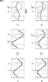
図11は、図10の情報提示処理で行われる消費電力U(m)の表示例を示す図である。 FIG. 11 is a diagram illustrating a display example of the power consumption U (m) performed in the information presentation process of FIG.
データ出力部16では、例えば、図11に示すように、各ファクタ#mに対応する家電#mの消費電力U(m)の時系列が、その家電#mの名称等の家電ラベルL(m)とともに、図示せぬディスプレイに表示される。 In the data output unit 16, for example, as shown in FIG. 11, the time series of the power consumption U (m) of the home appliance #m corresponding to each factor #m is converted into the home appliance label L (m ) And displayed on a display (not shown ) .
以上のように、監視システムでは、各ファクタが3以上の状態を有するFHMMによって、各家電の稼働状態をモデル化するFHMMの学習が行われるので、モードや設定等によって消費電力(電流)が変動するエアコン等の変動負荷家電について、正確な消費電力等を求めることができる。 As described above, in the monitoring system, the FHMM that models the operating state of each home appliance is learned by the FHMM having a factor of 3 or more, so the power consumption (current) varies depending on the mode and settings. Accurate power consumption and the like can be obtained for variable load home appliances such as air conditioners.
また、監視システムでは、配電盤等の1箇所で、家庭内の各家電で消費されている電流の総和を計測することにより、家庭内の各家電の消費電力を求めることができるので、各コンセントにスマートタップを取り付ける場合に比較して、コスト、及び、労力のいずれの面からも、容易に、家庭内の各家電の消費電力の「見える化」を実現することができる。 In addition, in the monitoring system, the power consumption of each household appliance in the home can be obtained by measuring the total current consumed by each household appliance at one location such as a switchboard. Compared with the case where a smart tap is attached, “visualization” of the power consumption of each home appliance in the home can be easily realized from both the cost and labor aspects.
そして、家庭内の各家電の消費電力の「見える化」によれば、例えば、家庭での節電の意識を高めることができる。 According to “visualization” of the power consumption of each home appliance in the home, for example, it is possible to raise awareness of power saving at home.
なお、監視システムで得られる家庭内の各家電の消費電力については、例えば、サーバ等で収集し、各家庭の家電の消費電力から、家電の使用時間帯、ひいていは、生活パターンを推定し、マーケティング等に役立てることができる。 In addition, the power consumption of each household electrical appliance obtained by the monitoring system is collected by, for example, a server, and the usage time zone of the household electrical appliance and the life pattern are estimated from the power consumption of each household electrical appliance. Can be used for marketing, etc.
[本技術を適用した監視システムの第2実施の形態] [Second embodiment of the monitoring system to which the present technology is applied]
図12は、本技術を適用した監視システムの第2実施の形態の構成例を示すブロックである。 FIG. 12 is a block diagram illustrating a configuration example of the second embodiment of the monitoring system to which the present technology is applied.
なお、図中、図3の場合と対応する部分については、同一の符号を付してあり、以下では、その説明は、適宜省略する。 In the figure, portions corresponding to those in FIG. 3 are denoted by the same reference numerals, and description thereof will be omitted below as appropriate.
図12の監視システムは、データ取得部11ないしデータ出力部16を有する点で、図3の監視システムと共通する。
The monitoring system of FIG. 12 is common to the monitoring system of FIG. 3 in that the
但し、図12の監視システムは、モデル学習部14の分散学習部32に代えて、個別分散学習部52が設けられている点で、図3の監視システムと相違する。
However, the monitoring system of FIG. 12 is different from the monitoring system of FIG. 3 in that an individual distributed learning
図3の分散学習部32では、分散学習において、全体モデルとしてのFHMMについて、1の分散Cが求められるが、図12の個別分散学習部52では、分散学習において、全体モデルとしてのFHMMについて、ファクタ#mごと、又は、各ファクタ#mの状態#kごとに、個別の分散(以下、個別分散ともいう)σ(m)が求められる。
In the distributed learning
ここで、個別分散σ(m)が、各ファクタ#mの状態#kごとに個別の分散である場合、個別分散σ(m)は、例えば、ファクタ#mの状態#kの分散σ(m) kを、k列目のコンポーネントとするK列の行ベクトルである。 Here, when the individual variance σ (m) is an individual variance for each state #k of each factor #m, the individual variance σ (m) is, for example, the variance σ (m (m ) A row vector of K columns, where k is a component of the kth column.
なお、以下では、説明を簡単にするため、個別分散σ(m)が、ファクタ#mごとに個別の分散である場合、個別分散σ(m)としてのK列の行ベクトルのすべてのコンポーネントσ(m) 1,σ(m) 2,・・・,σ(m) Kを、ファクタ#mに共通の同一の値(ファクタ#mについての分散としての同一のスカラ値、又は、(共分散)行列)とすることで、ファクタ#mごとに個別の個別分散σ(m)を、各ファクタ#mの状態#kごとに個別の個別分散σ(m)と同一に扱うこととする。 In the following, in order to simplify the description, when the individual variance σ (m) is an individual variance for each factor #m, all components σ of the row vector of K columns as the individual variance σ (m) (m) 1 , σ (m) 2 ,..., σ (m) K is the same value common to factor #m (the same scalar value as the variance for factor #m or (covariance ) Matrix), the individual individual variance σ (m) for each factor #m is treated the same as the individual individual variance σ (m) for each state #k of each factor #m.
個別分散σ(m)としてのK列の行ベクトルのk列目のコンポーネントであるファクタ#mの状態#kの分散σ(m) kは、分散としてのスカラ値、又は、共分散行列としてのD行D列の行列である。 Individual variance sigma variance sigma (m) k states #k factors #m is k-th column component row vector of K rows of a (m) is a scalar value as a dispersion, or, as a covariance matrix D-by-D matrix.
個別分散学習部52において、個別分散σ(m)が求められる場合、評価部21では、その個別分散σ(m)を用い、式(4)に代えて、式(16)に従って、観測確率P(Yt|St)が求められる。
When the individual variance σ (m) is obtained in the individual
ここで、式(16)のΣtは、式(17)に従って求められる。 Here, sigma t of formula (16) is determined according to equation (17).
S*(m) tは、式(6)に示したように、時刻tにいるファクタ#mの状態を表し、K行のうちの1行のみのコンポーネントが0で、他の行のコンポーネントが0のK行の列ベクトルである。 S * (m) t represents the state of factor #m at time t, as shown in equation (6), where only one of the K rows has 0 component and the other row has components It is a column vector of 0 K rows.
個別分散学習部52において、個別分散σ(m)は、以下のようにして求められる。
In the individual
すなわち、実際に計測(観測)される計測波形Ytに対する全体モデルφとしてのFHMMの分散σの期待値<σ>は、式(18)に示すように、計測波形Ytとしての電流波形と、全体モデルφとしてのFHMMにおいて生成(観測)される生成波形Y^tとしての電流波形との自乗誤差|Yt-Y^t|2の期待値<|Yt-Y^t|2>に等しい。 That is, the expected value <σ> of the variance σ of the FHMM as the overall model φ with respect to the measurement waveform Y t that is actually measured (observed) is the current waveform as the measurement waveform Y t as shown in Equation (18). Expected value of square error | Y t -Y ^ t | 2 <| Y t -Y ^ t | 2 > with current waveform as generated waveform Y ^ t generated (observed) in FHMM as overall model φ be equivalent to.
![]()
![]()
分散σの期待値<σ>は、各ファクタ#mの状態#kごとに個別の個別分散σ(m)の期待値σ(m)<S(m) t>のファクタ#mについての総和σ(1)<S(1) t>+σ(2)<S(2) t>+・・・+σ(M)<S(M) t>に等価である。 Expected value <σ> of variance σ is the sum σ of expected values σ (m) <S (m) t > of factor #m of individual individual variance σ (m) for each state #k of factor #m (1) <S (1) t > + σ (2) <S (2) t > +... + Σ (M) <S (M) t > is equivalent.
また、計測波形Ytと生成波形Y^tとの自乗誤差|Yt-Y^t|2の期待値<|Yt-Y^t|2>は、計測波形Ytと、個別波形W(m)の期待値W(m)<S(m) t>のファクタ#mについての総和W(1)<S(1) t>+W(2)<S(2) t>+・・・+W(M)<S(M) t>との自乗誤差|Yt-(W(1)<S(1) t>+W(2)<S(2) t>+・・・+W(M)<S(M) t>)|2に等価である。 Also, the expected value <| Y t -Y ^ t | 2 > of the squared error | Y t -Y ^ t | 2 between the measured waveform Y t and the generated waveform Y ^ t is the measured waveform Y t and the individual waveform W the sum of the expected value W (m) factor #m of <S (m) t> of (m) W (1) < S (1) t> + W (2) <S (2) t> + ··・ Square error with + W (M) <S (M) t > | Y t- (W (1) <S (1) t > + W (2) <S (2) t > + ... + W (M) <S (M ) t>) | is equivalent to 2.
したがって、式(18)は、式(19)と等価である。 Therefore, equation (18) is equivalent to equation (19).
式(19)を満たす個別分散σ(m)=σ(m)newは、個別分散σ(m)が負ではないという制約がある制約付き2次計画法により、式(20)に従って求めることができる。 Individual variance σ (m) = σ (m) new satisfying equation (19) can be obtained according to equation (20) by constrained quadratic programming with a constraint that individual variance σ (m) is not negative. it can.
個別分散学習部52は、式(20)に従って、個別分散σ(m)の更新値σ(m)newを求め、その更新値σ(m)newによって、モデル記憶部13に記憶された個別分散σ(m)を更新する。
The individual
以上のように、個別分散学習部52において、ファクタ#mごと、又は、各ファクタ#mの状態#kごとの個別分散σ(m)を求める場合には、1の分散Cを用いる場合よりも、全体モデルφとしてのFHMMの、家電を表現する表現能力が向上するとともに、推定部22での状態推定の精度が向上するので、より正確な消費電力等を求めることができる。
As described above, in the individual
特に、例えば、吸引の状態によって消費電流がばらつく掃除機等の変動負荷家電について、個別分散σ(m)を用いることにより、より正確な消費電力を求めることができる。 In particular, more accurate power consumption can be obtained by using the individual variance σ (m) for a variable load home appliance such as a vacuum cleaner whose current consumption varies depending on the suction state.
図12の監視システムでは、分散Cに代えて、個別分散σ(m)が用いられることを除き、図3の監視システムと同様の処理(図6の学習処理や、図10の情報提示処理)が行われる。 In the monitoring system of FIG. 12, processing similar to that of the monitoring system of FIG. 3 (learning processing of FIG. 6 and information presentation processing of FIG. 10 ) is performed except that individual variance σ (m) is used instead of variance C. Is done.
図13は、図12の監視システムが、図6のステップS13で行うEステップの処理を説明するフローチャートである。 FIG. 13 is a flowchart for explaining the process of step E performed by the monitoring system of FIG. 12 in step S13 of FIG.
ステップS61において、評価部21は、モデル記憶部13に記憶された全体モデルφとしてのFHMMの個別分散σ(m)、及び、固有波形W(m)、並びに、データ取得部11からの計測波形Yt={Y1,Y2,・・・,YT}を用い、各時刻t={1,2,・・・,T}の、状態の各組み合わせStについて、(式(4)ではなく)式(16)及び式(17)に従って、観測確率P(Yt|St)を求め、推定部22に供給して、処理は、ステップS62に進む。
In step S <b> 61, the
以下、ステップS62ないしS66では、図7のステップS22ないしS26とそれぞれ同様の処理が行われる。 Thereafter, in steps S62 to S66, the same processes as those in steps S22 to S26 of FIG. 7 are performed.
図14は、図12の監視システムが、図6のステップS14で行うMステップの処理を説明するフローチャートである。 FIG. 14 is a flowchart for explaining the process of the M step performed in step S14 of FIG. 6 by the monitoring system of FIG.
ステップS71において、波形分離学習部31は、図9のステップS31と同様に、波形分離学習によって、固有波形W(m)の更新値W(m)newを求め、その更新値W(m)newによって、モデル記憶部13に記憶された固有波形W(m)を更新して、処理は、ステップS72に進む。
In step S71, the waveform
ステップS72では、個別分散学習部52が、データ取得部11からの計測波形Yt、推定部22からの事後確率<S(m) t>、及び、及び、モデル記憶部13に記憶された固有波形W(m)を用いて、分散学習としての式(20)に従って、個別分散σ(m)の更新値σ(m)newを求める。
In step S < b > 72, the individual
そして、個別分散学習部52は、、個別分散σ(m)の更新値σ(m)newによって、モデル記憶部13に記憶された個別分散σ(m)を更新し、処理は、ステップS72からステップS73に進む。
Then, the individual
ステップS73では、状態変動学習部33は、図9のステップS33と同様に、状態変動学習によって、遷移確率P(m) i,jの更新値P(m) i,j new、及び、初期状態確率π(m)の更新値π(m)newを求め、その更新値P(m) i,j new、及び、π(m)newによって、モデル記憶部13に記憶された遷移確率P(m) i,j、及び、初期状態確率π(m)を更新して、Mステップの処理からリターンする。
In step S73, the state
[本技術を適用した監視システムの第3実施の形態] [Third embodiment of a monitoring system to which the present technology is applied]
図15は、本技術を適用した監視システムの第3実施の形態の構成例を示すブロックである。 FIG. 15 is a block diagram illustrating a configuration example of the third embodiment of the monitoring system to which the present technology is applied.
なお、図中、図3の場合と対応する部分については、同一の符号を付してあり、以下では、その説明は、適宜省略する。 In the figure, portions corresponding to those in FIG. 3 are denoted by the same reference numerals, and description thereof will be omitted below as appropriate.
図15の監視システムは、データ取得部11ないしデータ出力部16を有する点で、図3の監視システムと共通する。
The monitoring system in FIG. 15 is common to the monitoring system in FIG. 3 in that the
但し、図15の監視システムは、状態推定部12の推定部22に代えて、近似推定部42が設けられている点で、図3の監視システムと相違する。
However, the monitoring system of FIG. 15 is different from the monitoring system of FIG. 3 in that an
近似推定部42は、1時刻に状態が遷移するファクタの数を制限する状態遷移制限の下で、事後確率(状態確率)<S(m) t>等を求める。
The
ここで、例えば、事後確率<S(m) t>は、式(9)に従い、事後確率γt,zを周辺化することで求められる。 Here, for example, the posterior probability <S (m) t > is obtained by peripheralizing the posterior probability γ t, z according to the equation (9).
事後確率γt,zは、式(8)に従い、前向き確率αt,zと後ろ向き確率βt,zを用い、FHMMの各ファクタの状態の組み合わせzすべてについて求められる。 The posterior probability γ t, z is obtained for all combinations z of the states of each factor of the FHMM using the forward probability α t, z and the backward probability β t, z according to equation (8).
ところで、FHMMの各ファクタの状態の組み合わせzの数は、KM通りだけ存在し、ファクタの数Mの増加に対して、指数のオーダで増加する。 Incidentally, the number of combinations z status of each factor FHMM is present only K M Street, with an increase in the number M of factors, increasing the order of the exponent.
したがって、FHMMが、ある程度の数のファクタを有する場合に、各ファクタの状態の組み合わせzすべてについて、前向き確率αt,z、及び、後ろ向き確率βt,z、さらには、事後確率γt,zを、文献Aに記載されているように厳密に計算するのでは、計算量が膨大になる。 Therefore, when the FHMM has a certain number of factors, the forward probability α t, z and the backward probability β t, z and further the posterior probability γ t, z for all the state combinations z of each factor. Is strictly calculated as described in Document A, the calculation amount is enormous.
そこで、FHMMの状態推定については、例えば、Gibbs Samplingや、Completely Factorized Variational Approximation、Structured Variational Approximation等の近似推定手法が文献Aにおいて提案されている。しかしながら、これらの近似推定手法では、計算量が依然として大きいことや、近似による精度の低下が著しいことがある。 Thus, for estimation of the state of the FHMM, for example, an approximation estimation method such as Gibbs Sampling, Completely Factorized Variational Approximation, or Structured Variational Approximation is proposed in Document A. However, in these approximate estimation methods, the amount of calculation is still large, and the accuracy may be significantly reduced due to the approximation.
ところで、家庭内のすべての家電の稼働状態が、各時刻に変化(変動)する可能性は、停電等の異常なケースを除けば、極めて低い。 By the way, the possibility that the operating states of all household appliances in the home change (fluctuate) at each time is extremely low except for an abnormal case such as a power failure.
そこで、近似推定部42は、1時刻に状態が遷移するファクタの数を制限する状態遷移制限の下で、事後確率<S(m) t>等を求める。
Therefore, the
状態遷移制限としては、1時刻に状態が遷移するファクタの数を、例えば、1個や数個等以下に制限することを採用することができる。 As the state transition restriction, it is possible to adopt limiting the number of factors that cause a state transition at one time to one or several or less.
状態遷移制限によれば、事後確率<S(m) t>等を求めるのに用いられる事後確率γt,z、ひいては、前向き確率αt,z、及び、後ろ向き確率βt,zを、厳密に計算する必要がある状態の組み合わせzの数が、大幅に削減され、さらに、その削減される状態の組み合わせは、生じる可能性が極めて低い組み合わせであるため、事後確率(状態確率)<S(m) t>等の精度を大きく損なうことなく、計算量を大幅に少なくすることができる。 According to the state transition restriction, the posterior probability γ t, z used for obtaining the posterior probability <S (m) t >, etc., and hence the forward probability α t, z and the backward probability β t, z are strictly Since the number of state combinations z that need to be calculated in is greatly reduced, and the reduced state combinations are very unlikely to occur, posterior probabilities (state probabilities) <S ( m) The amount of calculation can be greatly reduced without significantly degrading the accuracy such as t >.
近似推定部42において、1時刻に状態が遷移するファクタの数を制限する状態遷移制限の下で、事後確率<S(m) t>等を求める方法としては、Eステップの処理に、パーティクルフィルタを適用する方法、すなわち、FHMMの状態の組み合わせzに、パーティクルフィルタを適用する方法がある。
As a method of obtaining the posterior probability <S (m) t > and the like under the state transition restriction that restricts the number of factors that cause state transition at one time in the
ここで、パーティクルフィルタについては、例えば、上述の文献Bの364ページに記載されている。 Here, the particle filter is described, for example, on page 364 of the above-mentioned document B.
また、本実施の形態では、状態遷移制限として、1時刻に状態が遷移するファクタの数を、例えば、1個以下に制限することを採用することとする。 In the present embodiment, as the state transition restriction, it is assumed that the number of factors causing a state transition at one time is limited to, for example, one or less.
FHMMの状態の組み合わせzに、パーティクルフィルタを適用する場合、パーティクルフィルタのp番目のパーティクルSpは、FHMMの状態のある組み合わせを表現する。 The combination z states FHMM, when applying the particle filter, p-th particle S p of the particle filter, to represent some combination of state of the FHMM.
ここで、パーティクルSpは、そのパーティクルSpが表現する、ファクタ#1の状態S(1) p、ファクタ#2の状態S(2) p、・・・、ファクタ#Mの状態S(M) pの組み合わせであり、式Sp={S(1) p,S(2) p,・・・,S(M) p}で表現される。
Here, the particle S p, the particles S p is expressed,
また、FHMMの状態の組み合わせzに、パーティクルフィルタを適用する場合、状態の組み合わせStにおいて、計測波形Ytが観測される式(4)の観測確率P(Yt|St)に代えて、パーティクルSp(が表現する状態の組み合わせ)において、計測波形Ytが観測される観測確率P(Yt|Sp)が用いられる。 Further, the combination z states FHMM, when applying the particle filter, in combination S t states, observation probability P of formula measurement waveform Y t is observed (4) | instead of (Y t S t) , The observation probability P (Y t | S p ) at which the measurement waveform Y t is observed is used in the particle S p (a combination of states represented by).
観測確率P(Yt|Sp)は、例えば、式(21)に従って計算することができる。 The observation probability P (Y t | S p ) can be calculated, for example, according to the equation (21).
式(21)の観測確率P(Yt|Sp)は、平均値(平均ベクトル)が、μtではなく、μpである点で、式(4)の観測確率P(Yt|St)と異なっている。 Wherein the observation probability P (21) (Y t | S p) is the mean value (mean vector) is the mu t rather, mu is a point p, the observation probability P (Y t of formula (4) | S t ) is different.
平均値μpは、平均値μtと同様に、電流波形Ytと同様のD行の列ベクトルであり、固有波形W(m)を用いて、式(22)で表される。 I mean mu p, as well as the average value mu t, a column vector of D rows similar to the current waveform Y t, using a unique waveform W (m), the formula (22).
ここで、S*(m) pは、パーティクルSpとしての状態の組み合わせを構成する状態のうちの、ファクタ#mの状態を表し、以下、パーティクルSpのファクタ#mの状態S*(m) pともいう。パーティクルSpのファクタ#mの状態S*(m) pは、例えば、式(23)に示すように、K行のうちの1行のみのコンポーネントが0で、他の行のコンポーネントが0のK行の列ベクトルである。 Here, S * (m) p is of the states constituting the combination of the states of the particles S p, represents the state of the factor #m, following the state of factor #m particles S p S * (m ) Also called p . State S * (m) p factors #m particles S p, for example, as shown in equation (23), with component 0 of only one row of the K line, the other line component is 0 It is a column vector of K rows.
パーティクルSpとしての状態の組み合わせを構成するファクタ#mの状態が、状態#kである場合、パーティクルSpのファクタ#mの状態S*(m) pとしてのK行の列ベクトルS*(m) pは、k行目のコンポーネントだけが1とされ、他のコンポーネントは0とされる。 If the state of factor #m that constitutes the combination of states as particles S p is state #k, column vector S * ( K rows as factors S * (m) p of factor #m of particles S p m) For p , only the component in the k-th row is set to 1, and the other components are set to 0.
式(22)によれば、パーティクルSpとしての状態の組み合わせを構成する各ファクタ#mの状態#kの固有波形W(m) kの総和が、時刻tの電流波形Ytの平均値μpとして求められる。 According to equation (22), the particles S sum of unique waveform W (m) k states #k of each factor #m constituting the combination of the states of the p has an average value of the current waveform Y t at time t mu Calculated as p .
図16は、FHMMの状態の組み合わせzに、パーティクルフィルタを適用して、前向き確率αt,pを求める方法を説明する図である。 FIG. 16 is a diagram for explaining a method of obtaining the forward probability α t, p by applying a particle filter to the combination z of FHMM states.
なお、図16では(後述する図17及び図18でも同様)、例えば、FHMMのファクタの数が4個であり、各ファクタが、オン状態とオフ状態とを稼働状態として表す2個の状態を有することとする。 In FIG. 16 (the same applies to FIGS. 17 and 18 to be described later), for example, the number of FHMM factors is four, and each factor represents two states representing an on state and an off state as operating states. I will have it.
評価部21は、モデル記憶部13に記憶された全体モデルφとしてのFHMMの分散C、及び、固有波形W(m)、並びに、データ取得部11からの計測波形Yt={Y1,Y2,・・・,YT}を用い、各時刻t={1,2,・・・,T}の、各パーティクルSp={S1,S2,・・・,SR}としての状態の組み合わせについて、式(21)の観測確率P(Yt|Sp)を求め、近似推定部42に供給する。
The
そして、近似推定部42は、評価部21からの観測確率P(Yt|Sp)、及び、モデル記憶部13に記憶された全体モデルφとしてのFHMMの遷移確率P(m) i,j(及び初期状態確率π(m))を用いて、計測波形Y1,Y2,・・・,Ytを観測し、時刻tに、パーティクルSpとしての状態の組み合わせにいる前向き確率αt,pを求める。
Then, the
前向き確率αt,pは、例えば、1時刻前の前向き確率αt-1,rを用いた漸化式αt,p=Σαt-1,rP(Sp|r)P(Yt|Sp)に従って求めることができる。
Forward probability alpha t, p are, for example,
漸化式αt,p=Σαt-1,rP(Sp|r)P(Yt|Sp)において、rは、1時刻に状態が遷移するファクタの数を1状態以下に制限する状態遷移制限の下で、時刻tのパーティクルSpとしての状態の組み合わせに遷移することができる時刻t-1のパーティクルとしての状態の組み合わせrを表す。 In the recurrence formula α t, p = Σα t-1, r P (S p | r) P (Y t | S p ), r limits the number of factors that change state at one time to 1 state or less under the state transition restrictions that represents the combination r state as time t-1 of particles can transition to a combination of states of the particles S p of time t.
したがって、状態の組み合わせrとなり得るのは、パーティクルSpとしての状態の組み合わせと同一の状態の組み合わせと、パーティクルSpとしての状態の組み合わせとは1個だけ状態が異なる状態の組み合わせとなる。 Therefore, can become a combination of state r is a combination of the same state and the combination of the states of the particles S p, only one state is a combination of state different from the combination of the states of the particles S p.
漸化式αt,p=Σαt-1,rP(Sp|r)P(Yt|Sp)において、Σは、状態の組み合わせrすべてについてとるサメーションを表す。 In the recurrence formula α t, p = Σα t−1, r P (S p | r) P (Y t | S p ), Σ represents the summation taken for all the combinations r of states.
また、漸化式αt,p=Σαt-1,rP(Sp|r)P(Yt|Sp)において、P(Sp|r)は、時刻t-1にパーティクルとしての状態の組み合わせrにいて、時刻tにパーティクルSpとしての状態の組み合わせに遷移する遷移確率を表し、全体モデルφとしてのFHMMの遷移確率P(m) i,jを用い、式(3)に従って求められる。 In addition, in the recurrence formula α t, p = Σα t-1, r P (S p | r) P (Y t | S p ), P (S p | r) is expressed as a particle at time t−1. state combinations r Niite represents the transition probability of transition to the combination of the states of the particles S p at time t, using transition probability P (m) i, j of the FHMM for the entire model phi, according to equation (3) Desired.
なお、前向き確率αt,pの初期値としては、例えば、状態の組み合わせすべての中から、パーティクルSpとして、ランダムに選択される状態の組み合わせを構成する各ファクタ#mの状態#kの初期状態確率π(m) kの積が採用される。 As the initial value of the forward probability alpha t, p, for example, from combination of the states of all, as particles S p, the state #k of each factor #m constituting the combination of conditions selected randomly initial A product of state probabilities π (m) k is adopted.
近似推定部42は、FHMMが取り得る状態の組み合わせのすべてではなく、パーティクルSpとしての状態の組み合わせについてだけ、前向き確率αt,pを求める。
時刻tに存在するパーティクルSpの数をR個とすると、R個の前向き確率αt,pが求められる。 When the number of particles S p present in the time t and the R, R-number of forward probability α t, p is required.
近似推定部42は、時刻tのR個のパーティクルSp={S1,S2,・・・,SR}について、前向き確率αt,pを求めると、その前向き確率αt,pに基づいて、R個のパーティクルSp={S1,S2,・・・,SR}の中からのパーティクルのサンプリングを行う。
When the
すなわち、近似推定部42は、R個のパーティクルSp={S1,S2,・・・,SR}の中から、前向き確率αt,pの大きい順に、所定数であるP個のパーティクルSp={S1,S2,・・・,SP}をサンプリングし、そのP個のパーティクルSpだけを、時刻tのパーティクルとして残す。
That is, the
なお、P≧Rの場合は、R個のパーティクルSpすべてがサンプリングされる。 In the case of P ≧ R, R-number of particles S p all is sampled.
また、パーティクルSpをサンプリングする個数Pは、FHMMが取り得る状態の組み合わせの数よりも小さい値であり、例えば、監視システムに許容される計算コスト等に基づいて設定される。 The number P of sampling particles S p is a value smaller than the number of combinations of possible states is FHMM, for example, is set based on the calculated cost, and the like which are acceptable to the monitoring system.
近似推定部42は、時刻tのP個のパーティクルSp={S1,S2,・・・,SP}をサンプリングすると、そのP個のパーティクルSp={S1,S2,・・・,SP}それぞれについて、1時刻後である時刻t+1のパーティクルを、状態遷移制限の下で予測する。
1時刻に状態が遷移するファクタの数を1状態以下に制限する状態遷移制限の下では、時刻t+1のパーティクルSqとしては、パーティクルSpとしての状態の組み合わせと同一の状態の組み合わせと、パーティクルSpとしての状態の組み合わせとは1個だけ状態が異なる状態の組み合わせとが予測される。
Under the state
上述したように、FHMMのファクタの数が4個であり、各ファクタが、オン状態とオフ状態とを稼働状態として表す2個の状態を有する場合には、時刻tのあるパーティクルSpについては、その時刻tのパーティクルSpとしての状態の組み合わせと同一の1通りの状態の組み合わせと、時刻tのパーティクルSpとしての状態の組み合わせとは1個だけ状態が異なる4通りの状態の組み合わせとの、合計で5通りの組み合わせが、時刻t+1のパーティクルSqとして予測される。
As described above, a four number of factors FHMM, each factor is, if having two states representing an ON state and an OFF state as operating states, for particles S p with time t , a combination of the states of the
近似推定部42は、時刻t+1のパーティクルSq={S1,S2,・・・,SQ}の予測後、その時刻t+1のパーティクルSqについて、時刻tのパーティクルSpの場合と同様に、前向き確率αt+1,qを求め、以下、同様にして、各時刻t=1,2,・・・,Tの前向き確率を求める。
After predicting the particle S q = {S 1 , S 2 ,..., S Q } at
以上のように、近似推定部42は、各ファクタ#mの状態の組み合わせを、パーティクルとして、1時刻後のパーティクルを、状態遷移制限の下で予測し、前向き確率αt,zに基づいて、所定数のパーティクルをサンプリングすることを繰り返しながら、各時刻tについて、パーティクルとしての状態の組み合わせzの前向き確率αt,zを求める。
As described above, the
図17は、FHMMの状態の組み合わせzに、パーティクルフィルタを適用して、後ろ向き確率βt,pを求める方法を説明する図である。 FIG. 17 is a diagram for explaining a method of obtaining a backward probability β t, p by applying a particle filter to a combination z of FHMM states.
近似推定部42は、評価部21からの観測確率P(Yt|St)、及び、モデル記憶部13に記憶された全体モデルφとしてのFHMMの遷移確率P(m) i,jを用いて、時刻tに、パーティクルSpとしての状態の組み合わせにいて、その後、計測波形Yt,Yt+1,・・・,YTを観測する後ろ向き確率βt,pを求める。
The
後ろ向き確率βt,pは、例えば、1時刻後の後ろ向き確率βt+1,rを用いた漸化式βt,p=ΣP(Yt|Sp)P(r|Sp)βt+1,rに従って求めることができる。 The backward probability β t, p is, for example, a recurrence formula β t, p = ΣP (Y t | S p ) P (r | S p ) β t using the backward probability β t + 1, r after one time It can be found according to + 1, r .
漸化式βt,p=ΣP(Yt|Sp)P(r|Sp)βt+1,rにおいて、rは、1時刻に状態が遷移するファクタの数を1状態以下に制限する状態遷移制限の下で、時刻tのパーティクルSpとしての状態の組み合わせから遷移することができる時刻t+1のパーティクルとしての状態の組み合わせrを表す。 In the recurrence formula β t, p = ΣP (Y t | S p ) P (r | S p ) β t + 1, r , r limits the number of factors that change state at one time to 1 state or less under the state transition restrictions that represents the combination r state as time t + 1 of particles can transition from a combination of conditions as particles S p of time t.
したがって、状態の組み合わせrとなり得るのは、パーティクルSpとしての状態の組み合わせと同一の状態の組み合わせと、パーティクルSpとしての状態の組み合わせとは1個だけ状態が異なる状態の組み合わせとなる。 Therefore, can become a combination of state r is a combination of the same state and the combination of the states of the particles S p, only one state is a combination of state different from the combination of the states of the particles S p.
漸化式βt,p=ΣP(Yt|Sp)P(r|Sp)βt+1,rにおいて、Σは、状態の組み合わせrすべてについてとるサメーションを表す。 In the recurrence formula β t, p = ΣP (Y t | S p ) P (r | S p ) β t + 1, r , Σ represents the summation taken for all the state combinations r.
また、漸化式βt,p=ΣP(Yt|Sp)P(r|Sp)βt+1,rにおいて、P(r|Sp)は、時刻tにパーティクルSpとしての状態の組み合わせにいて、時刻t+1にパーティクルとしての状態の組み合わせrに遷移する遷移確率を表し、全体モデルφとしてのFHMMの遷移確率P(m) i,jを用い、式(3)に従って求められる。
Furthermore, a recurrence formula beta t, p = .SIGMA.P in | | (S p r) β t + 1, r, P (Y t S p) P (r | S p) is the time t as a particle S p In the state combination, it represents the transition probability of transition to the state combination r as a particle at
なお、後ろ向き確率βt,pの初期値βT,pとしては、1が採用される。 Note that 1 is adopted as the initial value β T, p of the backward probability β t, p .
近似推定部42は、前向き確率αt,pと同様に、FHMMが取り得る状態の組み合わせのすべてではなく、パーティクルSpとしての状態の組み合わせについてだけ、後ろ向き確率βt,pを求める。
時刻tに存在するパーティクルSpの数をR個とすると、R個の後ろ向き確率βt,pが求められる。 When the number of particles S p present in the time t and the R, R-number of backward probability β t, p is required.
近似推定部42は、時刻tのR個のパーティクルSp={S1,S2,・・・,SR}について、後ろ向き確率βt,pを求めると、その後ろ向き確率βt,pに基づいて、R個のパーティクルSp={S1,S2,・・・,SR}の中からのパーティクルのサンプリングを行う。
When the
すなわち、近似推定部42は、前向き確率αt,pの場合と同様に、R個のパーティクルSp={S1,S2,・・・,SR}の中から、後ろ向き確率βt,pの大きい順に、所定数であるP個のパーティクルSp={S1,S2,・・・,SP}をサンプリングし、そのP個のパーティクルSpだけを、時刻tのパーティクルとして残す。
That is, the
近似推定部42は、時刻tのP個のパーティクルSp={S1,S2,・・・,SP}をサンプリングすると、そのP個のパーティクルSp={S1,S2,・・・,SP}それぞれについて、1時刻前である時刻t-1のパーティクルを、状態遷移制限の下で予測する。
1時刻に状態が遷移するファクタの数を1状態以下に制限する状態遷移制限の下では、時刻t-1のパーティクルSqとしては、パーティクルSpとしての状態の組み合わせと同一の状態の組み合わせと、時刻tのパーティクルSpとしての状態の組み合わせとは1個だけ状態が異なる状態の組み合わせとが予測される。
Under the state
上述したように、FHMMのファクタの数が4個であり、各ファクタが、オン状態とオフ状態とを稼働状態として表す2個の状態を有する場合には、時刻tのあるパーティクルSpについては、その時刻tのパーティクルSpとしての状態の組み合わせと同一の1通りの状態の組み合わせと、時刻tのパーティクルSpとしての状態の組み合わせとは1個だけ状態が異なる4通りの状態の組み合わせとの、合計で5通りの組み合わせが、時刻t-1のパーティクルSqとして予測される。
As described above, a four number of factors FHMM, each factor is, if having two states representing an ON state and an OFF state as operating states, for particles S p with time t , a combination of the states of the
近似推定部42は、時刻t-1のパーティクルSq={S1,S2,・・・,SQ}について、時刻tのパーティクルSpの場合と同様に、後ろ向き確率βt+1,qを求め、以下、同様にして、各時刻t=T,T-1,・・・,1の後ろ向き確率を求める。
以上のように、近似推定部42は、各ファクタ#mの状態の組み合わせを、パーティクルとして、1時刻前のパーティクルを、状態遷移制限の下で予測し、後ろ向き確率βt,zに基づいて、所定数のパーティクルをサンプリングすることを繰り返しながら、各時刻tについて、パーティクルとしての状態の組み合わせzの後ろ向き確率βt,zを求める。
As described above, the
図18は、FHMMの状態の組み合わせzに、パーティクルフィルタを適用して、事後確率γt,pを求める方法を説明する図である。 FIG. 18 is a diagram for explaining a method for obtaining a posteriori probability γ t, p by applying a particle filter to a combination z of FHMM states.
近似推定部42は、各時刻tにおいて、前向き確率αt,pが求められたパーティクル(以下、前向きパーティクルともいう)Spとしての状態の組み合わせと、後ろ向き確率βt,p'が求められたパーティクル(以下、後ろ向きパーティクルともいう)Sp'としての状態の組み合わせとが、同一の状態の組み合わせzである場合、その状態の組み合わせzについて、前向き確率αt,zと後ろ向き確率βt,zを用いて、式(23)に従い、全体モデルφとしてのFHMMにおいて、時刻tに、状態の組み合わせzにいる事後確率γt,zを求める。
ここで、式(24)の右辺の分母のΣは、wを、時刻tの前向きパーティクルSpと後ろ向きパーティクルSp'との両方に共通に残っている状態の組み合わせSp∩Sp'のすべてに変えてとるサメーションを表す。 Here, Σ of the denominator of the right side of the equation (24), w a 'state that both the remaining common combination S p ∩S p' forward particles S p and backward particles S p of time t It represents a summation that takes everything.
なお、時刻tに前向きパーティクルSpとして残っていない状態の組み合わせzの前向き確率αt,z、及び、時刻tに後ろ向きパーティクルSp'として残っていない状態の組み合わせzの後ろ向き確率βt,zは、例えば、いずれも、0とされる。 Incidentally, forward probability alpha t, z combinations z state does not remain as a positive particle S p at time t, and, backward probabilities of combinations z state does not remain as a backward particles S p 'at time t beta t, z For example, both are set to 0.
したがって、時刻tの前向きパーティクルSpと後ろ向きパーティクルSp'との両方に共通に残っている状態の組み合わせSp∩Sp'以外の状態の組み合わせの事後確率γt,zは、0となる。 Therefore, the posterior probability γ t, z of the combination of the states other than the combination S p ∩S p ′ of the state remaining in common to both the forward particle S p and the backward particle S p ′ at time t is 0. .
図15の監視システムでは、FHMMの状態の組み合わせzに、パーティクルフィルタを適用することにより、状態遷移制限の下で、事後確率<S(m) t>等を求めることを除き、図3の監視システムと同様の処理が行われる。 In the monitoring system of FIG. 15, the monitoring of FIG. 3 is performed except that the posterior probability <S (m) t > is obtained under the state transition restriction by applying a particle filter to the state combination z of the FHMM. Processing similar to the system is performed.
図19、及び、図20は、図15の監視システムが、図6のステップS13で行うEステップの処理を説明するフローチャートである。 FIGS. 19 and 20 are flowcharts for explaining the processing of the E step performed in step S13 of FIG. 6 by the monitoring system of FIG.
なお、図20は、図19に続くフローチャートである。 FIG. 20 is a flowchart following FIG.
ステップS81において、近似推定部42は、時刻(を表す変数)tを、前向き確率についての初期値としての1に初期化して、処理は、ステップS82に進む。
In step S81, the
ステップS82では、近似推定部42は、FHMMが取り得る状態の組み合わせの中から、所定の数の状態の組み合わせを、例えば、ランダムに、パーティクルSpとして選択(サンプリング)する。なお、ステップS82では、FHMMが取り得る状態の組み合わせすべてを、パーティクルSpとして選択することができる。
At step S82, the
近似推定部42は、パーティクルSpとしての状態の組み合わせについて、前向き確率αt,pの初期値α1,pを求め、処理は、ステップS82からステップS83に進む。
The
ステップS83では、時刻tが、計測波形Yt={Y1,Y2,・・・,YT}の系列の最後の時刻(系列長)Tに等しいかどうかを判定する。 In step S83, it is determined whether or not the time t is equal to the last time (sequence length) T of the sequence of the measurement waveform Y t = {Y 1 , Y 2 ,..., Y T }.
ステップS83において、時刻tが、計測波形Ytの系列の最後の時刻Tに等しくないと判定された場合、すなわち、時刻tが時刻T未満である場合、処理は、ステップS84に進み、近似推定部42は、所定の条件としての状態遷移制限の下で、パーティクルSpとしての状態の組み合わせについて、1時刻後である時刻t+1のパーティクルを予測し、処理は、ステップS85に進む。
If it is determined in step S83 that time t is not equal to the last time T of the series of measurement waveforms Y t , that is, if time t is less than time T, the process proceeds to step S84 and approximate estimation is performed.
ステップS85では、近似推定部42は、時刻tを1だけインクリメントして、処理は、ステップS86に進む。
In step S85, the
ステップS86では、評価部21は、モデル記憶部13に記憶された全体モデルφとしてのFHMMの分散C、及び、固有波形W(m)、並びに、データ取得部11からの計測波形Yt={Y1,Y2,・・・,YT}を用い、時刻tの、各パーティクルSp={S1,S2,・・・,SR}としての状態の組み合わせについて、式(21)の観測確率P(Yt|Sp)を求める。評価部21は、観測確率P(Yt|Sp)を、近似推定部42に供給して、処理は、ステップS86からステップS87に進む。
In step S86, the
ステップS87では、近似推定部42は、評価部21からの観測確率P(Yt|Sp)、及び、モデル記憶部13に記憶された全体モデルφとしてのFHMMの遷移確率P(m) i,jを用いて、計測波形Y1,Y2,・・・,Ytを観測し、時刻tに、パーティクルSpとしての状態の組み合わせにいる前向き確率αt,pを求め、処理は、ステップS88に進む。
In step S87, the
ステップS88では、近似推定部42は、前向き確率αt,pに基づき、パーティクルSpの中から、前向き確率αt,pの大きい順に、所定数のパーティクルをサンプリングし、時刻tのパーティクルとして残す。
In step S88, the
その後、処理は、ステップS88からステップS83に戻り、以下、同様の処理が繰り返される。 Thereafter, the process returns from step S88 to step S83, and the same process is repeated thereafter.
そして、ステップS83において、時刻tが、計測波形Ytの系列の最後の時刻Tに等しいと判定された場合、処理は、図20のステップS91に進む。 If it is determined in step S83 that the time t is equal to the last time T in the series of measurement waveforms Y t , the process proceeds to step S91 in FIG.
ステップS91では、近似推定部42は、時刻tを、後ろ向き確率についての初期値としてのTに初期化して、処理は、ステップS92に進む。
In step S91, the
ステップS92では、近似推定部42は、FHMMが取り得る状態の組み合わせの中から、所定の数の状態の組み合わせを、例えば、ランダムに、パーティクルSpとして選択する。なお、ステップS92では、FHMMが取り得る状態の組み合わせすべてを、パーティクルSpとして選択することができる。
In step S92, the
近似推定部42は、パーティクルSpとしての状態の組み合わせについて、後ろ向き確率βt,pの初期値αT,pを求め、処理は、ステップS92からステップS93に進む。
The
ステップS93では、時刻tが、計測波形Yt={Y1,Y2,・・・,YT}の系列の最初の時刻1に等しいかどうかを判定する。
In step S93, it is determined whether or not the time t is equal to the
ステップS93において、時刻tが、計測波形Ytの系列の最初の時刻1に等しくないと判定された場合、すなわち、時刻tが時刻1より大である場合、処理は、ステップS94に進み、近似推定部42は、所定の条件としての状態遷移制限の下で、パーティクルSpとしての状態の組み合わせについて、1時刻前である時刻t-1のパーティクルを予測し、処理は、ステップS95に進む。
If it is determined in step S93 that the time t is not equal to the
ステップS95では、近似推定部42は、時刻tを1だけデクリメントして、処理は、ステップS96に進む。
In step S95, the
ステップS96では、評価部21は、モデル記憶部13に記憶された全体モデルφとしてのFHMMの分散C、及び、固有波形W(m)、並びに、データ取得部11からの計測波形Yt={Y1,Y2,・・・,YT}を用い、時刻tの、各パーティクルSp={S1,S2,・・・,SR}としての状態の組み合わせについて、式(21)の観測確率P(Yt|Sp)を求める。評価部21は、観測確率P(Yt|Sp)を、近似推定部42に供給して、処理は、ステップS96からステップS97に進む。
In step S <b> 96, the
ステップS97では、近似推定部42は、評価部21からの観測確率P(Yt|St)、及び、モデル記憶部13に記憶された全体モデルφとしてのFHMMの遷移確率P(m) i,jを用いて、時刻tに、パーティクルSpとしての状態の組み合わせにいて、その後、計測波形Yt,Yt+1,・・・,YTを観測する後ろ向き確率βt,pを求め、処理は、ステップS98に進む。
In step S97, the
ステップS98では、近似推定部42は、後ろ向き確率βt,pに基づき、パーティクルSpの中から、後ろ向き確率βt,pの大きい順に、所定数のパーティクルをサンプリングし、時刻tのパーティクルとして残す。
In step S98, the
その後、処理は、ステップS98からステップS93に戻り、以下、同様の処理が繰り返される。 Thereafter, the processing returns from step S98 to step S93, and the same processing is repeated thereafter.
そして、ステップS93において、時刻tが、計測波形Ytの系列の最初の時刻1に等しいと判定された場合、処理は、ステップS99に進む。
If it is determined in step S93 that the time t is equal to the
ステップS99では、近似推定部42は、前向き確率αt,z(=αt,p)と後ろ向き確率βt,z(=βt,p)を用いて、式(24)に従い、全体モデルφとしてのFHMMにおいて、時刻tに、状態の組み合わせzにいる事後確率γt,zを求め、処理は、ステップS100に進む。
In step S99, the
以下、ステップS100及びS101では、図7のステップS25及びS26とそれぞれ同様の処理が行われ、事後確率<S(m) t>,<S(m) tS(n) t'>、及び、<S(m) t-1S(m) t>が求められる。
る。
Thereafter, in steps S100 and S101, the same processing as in steps S25 and S26 of FIG. 7 is performed, and the posterior probabilities <S (m) t >, <S (m) t S (n) t ′>, and <S (m) t-1 S (m) t > is obtained.
The
以上のように、近似推定部42において、FHMMの状態の組み合わせzに、パーティクルフィルタを適用することで、状態遷移制限の下で、事後確率<S(m) t>等を求めることにより、可能性が低い状態の組み合わせについての計算を省略し、事後確率<S(m) t>等の計算の効率化を図ることができる。
As described above, the
[本技術を適用した監視システムの第4実施の形態] [Fourth embodiment of a monitoring system to which the present technology is applied]
図21は、本技術を適用した監視システムの第4実施の形態の構成例を示すブロックである。 FIG. 21 is a block diagram illustrating a configuration example of the fourth embodiment of the monitoring system to which the present technology is applied.
なお、図中、図3の場合と対応する部分については、同一の符号を付してあり、以下では、その説明は、適宜省略する。 In the figure, portions corresponding to those in FIG. 3 are denoted by the same reference numerals, and description thereof will be omitted below as appropriate.
図21の監視システムは、データ取得部11ないしデータ出力部16を有する点で、図3の監視システムと共通する。
The monitoring system in FIG. 21 is common to the monitoring system in FIG. 3 in that it has a
但し、図21の監視システムは、モデル学習部14の波形分離学習部31に代えて、制約付き分離学習部51が設けられている点で、図3の監視システムと相違する。
However, the monitoring system of FIG. 21 is different from the monitoring system of FIG. 3 in that a restricted
図3の分離学習部31では、特に制約なしで、固有波形W(m)が求められるが、制約付き波形分離学習部51は、家電(家電分離)に特有の所定の制約の下で、固有波形W(m)を求める。
In the
ここで、図3の分離学習部31では、Mステップにおいて、固有波形W(m)の算出にあたり、特に、制約は課されていない。
Here, in the
そのため、図3の分離学習部31では、計測波形Ytが、複数の電流波形を重畳した波形であることのみを考慮して、波形分離学習により、固有波形W(m)が算出される。
Therefore, the
すなわち、図3の分離学習部31の波形分離学習では、計測波形Ytが、複数の電流波形を重畳した波形であるとして、その複数の電流波形としての固有波形W(m)に分離される。
That is, in the waveform separation learning of the
固有波形W(m)の算出に、何らの制約もない場合、波形分離学習の解の自由度(冗長性)、すなわち、計測波形Ytから分離することができる複数の電流波形の自由度は、非常に高ため、家電の電流波形としては不適切な電流波形としての固有波形W(m)が求められることがあり得る。 If there are no restrictions on the calculation of the eigen waveform W (m), the degree of freedom (redundancy) of the solution for waveform separation learning, that is, the degree of freedom for multiple current waveforms that can be separated from the measured waveform Y t is Since it is very high, a natural waveform W (m) as a current waveform that is inappropriate as the current waveform of home appliances may be required.
そこで、制約付き波形分離学習部51では、家電に特有の所定の制約の下で、波形分離学習を行うことで、家電の電流波形としては不適切な電流波形としての固有波形W(m)が求められることを防止し、家電の正確な電流波形としての固有波形W(m)を求める。
Therefore, the constrained waveform
ここで、所定の制約の下で行われる波形分離学習を、制約付き波形分離学習ともいう。 Here, the waveform separation learning performed under a predetermined restriction is also referred to as restricted waveform separation learning.
図21の監視システムでは、制約付き波形分離学習が行われることを除き、図3の監視システムと同様の処理が行われる。 In the monitoring system of FIG. 21, processing similar to that of the monitoring system of FIG. 3 is performed except that constrained waveform separation learning is performed.
制約付き波形分離学習において、家電に特有の制約としては、例えば、負荷制約や基底波形制約がある。 In restricted waveform separation learning, examples of restrictions unique to home appliances include load restrictions and base waveform restrictions.
負荷制約は、家電#mの電流波形としての固有波形W(m)と、家電#mにかかる電圧の電圧波形、すなわち、電流波形である計測波形Ytに対応する電圧波形Vtとの乗算により求められる家電の消費電力U(m)が、負の値にならない(家電#mが発電をしない)という制約である。 The load constraint is the multiplication of the intrinsic waveform W (m) as the current waveform of the home appliance #m and the voltage waveform V t corresponding to the voltage waveform of the voltage applied to the home appliance #m, that is, the measurement waveform Y t that is the current waveform. This is a restriction that the power consumption U (m) of the home appliance calculated by the above does not become a negative value (the home appliance #m does not generate power).
基底波形制約は、家電#mの各稼働状態の消費電流の電流波形である固有波形W(m)は、その家電#mについて、基底波形としてあらかじめ用意された複数の波形の1個以上の組み合わせで表現されるという制約である。 The base waveform constraint is the current waveform of the current consumption in each operating state of the home appliance #m. The unique waveform W (m) is a combination of one or more waveforms prepared in advance as the base waveform for the home appliance #m. It is a restriction that it is expressed by.
図22は、図21の監視システムが、負荷制約を課して行う図6のステップS14のMステップの処理を説明するフローチャートである。 FIG. 22 is a flowchart for explaining the process of step M14 in step S14 of FIG. 6 performed by the monitoring system of FIG.
ステップS121において、制約付き波形分離学習部51は、データ取得部11からの計測波形Yt、並びに、推定部22からの事後確率<S(m) t>、及び、<S(m) tS(n) t'>を用い、負荷制約の下で、波形分離学習を行うことにより、固有波形W(m)の更新値W(m)newを求め、その更新値W(m)newによって、モデル記憶部13に記憶された固有波形W(m)を更新して、処理は、ステップS122に進む。
In step S121, the constrained waveform
すなわち、制約付き波形分離学習部51は、負荷制約の下での波形分離学習として、式(25)を、制約付きの2次計画法を用いて解くことにより、固有波形W(m)の更新値W(m)newを求める。
That is, the constrained waveform
ここで、式(25)では、固有波形W(m)の更新値W(m)newとなる固有波形Wに、負荷制約としての式0≦V'Wを満たす制約が課されている。 Here, in Formula (25), the unique waveform W to be updated value W (m) new new unique waveform W (m), constraints satisfying the expression 0 ≦ V'W as load constraints are imposed.
Vは、計測波形Ytとしての電流波形に対応する電圧波形Vtを表すD行の列ベクトルであり、V'は、列ベクトルVを転置した行ベクトルである。 V is a column vector of D rows representing the voltage waveform V t corresponding to the current waveform as the measurement waveform Y t , and V ′ is a row vector obtained by transposing the column vector V.
なお、式(25)の固有波形の更新値Wnew、事後確率<St'>、及び、<StSt'>は、式(12)で説明したそれと一致する。 The updated value W new , the posterior probability <S t '>, and <S t S t '> in the equation (25) are the same as those described in the equation (12).
すなわち、固有波形の更新値Wnewは、D行K×M列の行列であり、その(m-1)K+k列の列ベクトルは、ファクタ#mの状態#kの固有波形W(m) kの更新値になっている。 That is, the update value W new of the eigen waveform is a matrix of D rows and K × M columns, and the column vector of (m−1) K + k columns is the eigen waveform W (m ) The updated value of k .
事後確率<St'>は、K×M列の行ベクトルであり、その(m-1)K+k列目のコンポーネントは、時刻tに、ファクタ#mの状態#kにいる状態確率になっている。 The posterior probability <S t '> is a row vector of K × M columns, and its (m-1) K + k column component is the state probability of being in state #k with factor #m at time t. It has become.
事後確率<StSt'>は、K×M行K×M列の行列であり、その(m-1)K+k行(n-1)K+k'列目のコンポーネントは、時刻tに、ファクタ#mの状態#kと、他のファクタ#nの状態#k'とにいる状態確率になっている。 The posterior probability <S t S t '> is a matrix of K × M rows and K × M columns, and the (m−1) K + k rows (n−1) K + k ′ column components are time t is the state probability of being in state #k of factor #m and in state #k ′ of other factor #n.
なお、式(25)の固有波形Wは、固有波形の更新値Wnewと同様のD行K×M列の行列であり、式(25)の右辺のargmin{X}のXを最小にする固有波形Wが、固有波形の更新値Wnewとして、2次計画法により求められる。 The characteristic waveform W in Expression (25) is a matrix of D rows and K × M columns similar to the update value W new of the characteristic waveform, and minimizes X of argmin {X} on the right side of Expression (25). The natural waveform W is obtained by quadratic programming as the update value W new of the natural waveform.
ステップS122及びS123では、図9のステップS32及びS33と同様の処理が行われる。 In steps S122 and S123, processing similar to that in steps S32 and S33 in FIG. 9 is performed.
図23は、負荷制約を説明する図である。 FIG. 23 is a diagram for explaining the load constraint.
すなわち、図23Aは、負荷制約のない波形分離学習により求められる電流波形としての固有波形W(m)を示しており、図23Bは、負荷制約の下で行われた波形分離学習により求められる電流波形としての固有波形W(m)を示している。 That is, FIG. 23A shows an eigen waveform W (m) as a current waveform obtained by waveform separation learning without load restriction, and FIG. 23B shows a current obtained by waveform separation learning performed under load restriction. The characteristic waveform W (m) is shown as a waveform.
なお、図23では、ファクタの数Mを2個として、ファクタ#1のある状態#kの固有波形W(1) kと、ファクタ#2のある状態#k'の固有波形W(2) k'とを示してある。
In FIG. 23, assuming that the number of factors M is two, the characteristic waveform W (1) k of state #k with
図23A及び図23Bでは、ファクタ#1の固有波形W(1) kである電流波形は、いずれも、電圧波形Vtと同相になっている。 In Figure 23A and 23B, the current waveform is unique waveform W (1) k factor # 1, both have become the voltage waveform V t and phase.
しかしながら、図23Aでは、負荷制約がされていないため、ファクタ#2の固有波形W(2) k'である電流波形は、電圧波形Vtと逆相になっている。
However, in FIG. 23A, since the load is not restricted, the current waveform that is the intrinsic waveform W (2) k ′ of
一方、図23Bでは、負荷制約が課された結果、ファクタ#2の固有波形W(2) k'である電流波形は、電圧波形Vtと同相になっている。
On the other hand, in FIG 23B, a result of the load are imposed, the current waveform is a
計測波形Ytは、図23Aに示したファクタ#1の固有波形W(1) kと、ファクタ#2の固有波形W(2) k'とに分離することもできるし、図23Bに示したファクタ#1の固有波形W(1) kと、ファクタ#2の固有波形W(2) k'とに分離することもできる。 The measured waveform Y t can be separated into the characteristic waveform W (1) k of factor # 1 shown in FIG. 23A and the characteristic waveform W (2) k ′ of factor # 2 as shown in FIG. 23B. It is also possible to separate the characteristic waveform W (1) k of factor # 1 and the characteristic waveform W (2) k ′ of factor # 2.
しかしながら、計測波形Ytを、図23Aに示したファクタ#1の固有波形W(1) kと、ファクタ#2の固有波形W(2) k'とに分離した場合には、固有波形W(2) k'が電圧波形Vtと逆相になっているファクタ#2に対応する家電#2は、発電を行っていることになり、適切な家電分離を行うことが困難となるおそれがある。
However, when the measurement waveform Y t is separated into the characteristic waveform W (1) k of factor # 1 and the characteristic waveform W (2) k ′ of factor # 2 shown in FIG. 23A, the characteristic waveform W ( Appliances # 2 2) k 'corresponds to a
一方、負荷制約を課した場合には、計測波形Ytは、図23Bに示したファクタ#1の固有波形W(1) kと、ファクタ#2の固有波形W(2) k'とに分離される。 On the other hand, when a load constraint is imposed, the measurement waveform Y t is separated into the characteristic waveform W (1) k of factor # 1 and the characteristic waveform W (2) k ′ of factor # 2 shown in FIG. 23B. Is done.
図23Bの固有波形W(1) k、及び、固有波形W(2) k'は、いずれも、電圧波形Vtと同相になっており、したがって、負荷制約によれば、ファクタ#1に対応する家電#1、及び、ファクタ#2に対応する家電#2が、いずれも、電力を消費する負荷であるとして、適切な家電分離を行うことができる。
Both the natural waveform W (1) k and the natural waveform W (2) k ′ in FIG. 23B are in phase with the voltage waveform V t, and therefore correspond to
図24は、基底波形制約を説明する図である。 FIG. 24 is a diagram for explaining the base waveform restriction.
図24において、Yは、D行の列ベクトルである計測波形Ytが、時刻t順に、左から右方向に並んだD行T列の行列である。D行T列の行列である計測波形Yのt列目の列ベクトルは、時刻tの計測波形Ytになっている。 In FIG. 24, Y is a matrix of D rows and T columns in which measured waveforms Y t that are column vectors of D rows are arranged from left to right in the order of time t. Column vector of t th column of D rows and T is a matrix of rows measurement waveform Y is adapted to measure the waveform Y t at time t.
図24において、Wは、D行K列の行列であるファクタ#mの固有波形W(m)が、ファクタ#m順に、左から右方向に並んだD行K×M列の行列である。D行K×M列の行列である固有波形Wの(m-1)K+k列の列ベクトルは、ファクタ#mの状態#kの固有波形W(m) kになっている。 In FIG. 24, W is a matrix of D rows and K × M columns in which the intrinsic waveform W (m) of factor #m, which is a matrix of D rows and K columns, is arranged in the order of factor #m from left to right. The column vector of (m−1) K + k columns of the eigen waveform W that is a matrix of D rows and K × M columns is the eigen waveform W (m) k of the state #k with the factor #m.
図24において、Fは、K×Mを表す。 In FIG. 24, F represents K × M.
図24において、<St>は、K行の列ベクトルである時刻tの事後確率<S(m) t>がファクタ#m順に上から下方向に並んだF=K×M行の列ベクトルが、時刻t順に、左から右方向に並んだをK×M行T列の行列である。K×M行T列の行列である事後確率<St>の(m-1)K+k行t列目のコンポーネントは、時刻tに、ファクタ#mの状態#kにいる状態確率になっている。 In FIG. 24, <S t > is a column vector of F = K × M rows in which posterior probabilities <S (m) t > at time t, which are column vectors of K rows, are lined up from top to bottom in the order of factor #m. Is a matrix of K × M rows and T columns arranged from left to right in order of time t. The component of the (m-1) K + k rows and t columns of the posterior probability <S t > that is a matrix of K × M rows and T columns becomes the state probability of being in state #k with factor #m at time t. ing.
波形分離学習では、FHMMにおいて、図24に示すように、固有波形Wと事後確率<St>との積W×<St>が、計測波形Yとして観測されることとして、固有波形Wが求められる。 In the waveform separation learning, as shown in FIG. 24, in the FHMM, the product W × <S t > of the eigen waveform W and the posterior probability <S t > is observed as the measured waveform Y. Desired.
基底波形制約は、上述したように、家電#mの各稼働状態の消費電流の電流波形である固有波形W(m)が、その家電#mについて、基底波形としてあらかじめ用意された複数の波形の1個以上の組み合わせで表現されるという制約であるため、基底波形制約を課した波形分離学習では、図24に示すように、固有波形Wが、所定の数Nの基底波形Bと、所定の係数Aとの積B×Aで表されることとして、固有波形Wが求められる。 As described above, the base waveform constraint is that the specific waveform W (m) , which is the current waveform of the consumption current of each operating state of the home appliance #m, has a plurality of waveforms prepared in advance as base waveforms for the home appliance #m. In the waveform separation learning that imposes the base waveform restriction, as shown in FIG. 24, the eigen waveform W includes a predetermined number N of base waveforms B, a predetermined number of combinations, and the like. The characteristic waveform W is obtained as represented by the product B × A with the coefficient A.
ここで、所定の数Nの基底波形Bのうちの、n番目の基底波形Bを、Bnと表すこととすると、Bnは、例えば、波形のサンプル値をコンポーネントとするD行の列ベクトルであり、基底波形Bは、D行の列ベクトルである基底波形Bnが、インデクスn順に、左から右方向に並んだD行N列の行列である。 Here, among the base waveform B of a predetermined number N, the n-th base waveform B, When be expressed as B n, B n, for example, a column vector of D rows and component sample values of the waveform The base waveform B is a matrix of D rows and N columns in which the base waveform B n, which is a column vector of D rows, is arranged from left to right in the order of index n.
係数Aは、N行K×M列の行列であり、n行(m-1)K+k列目のコンポーネントは、固有波形W(m) kを、N個の基底波形B1,B2,・・・,BNの組み合わせ(重畳)で表現するのに、n番目の基底波形Bnに乗算される係数になっている。 The coefficient A is a matrix of N rows and K × M columns, and the component in the nth row (m−1) K + k column is the eigen waveform W (m) k and the N base waveforms B 1 and B 2. ,..., B N are coefficients that are multiplied by the nth base waveform B n to represent the combination (superimposition).
ここで、固有波形W(m) kを、N個の基底波形B1ないしBNの組み合わせで表現するのに、N個の基底波形B1ないしBNと乗算される係数としての、例えば、N行の列ベクトルを、係数A(m) kと表し、その係数A(m) kを、ファクタ#mのK個の状態#1ないし#Kの順に、左から右方向に並べたN行K列の行列を、係数A(m)と表すこととすると、係数Aは、係数A(m)を、ファクタ#m順に、左から右方向に並べた行列である。 Here, the unique waveform W (m) k, to express a combination of N base waveform B 1 to B N, as coefficients to the N base waveform B 1 not being multiplied with the B N, for example, An N-row column vector is represented as a coefficient A (m) k, and the coefficient A (m) k is arranged in N rows in the order of K states # 1 to #K in factor #m from left to right. a matrix of K rows, when it represents a coefficient a (m), the coefficient a is a coefficient a (m), factor #m turn, is a matrix arranged from left to right.
基底波形Bは、例えば、画像処理等で用いられるICA(Independent Component Analysis)やNMF(Non-negative Matrix Factorization)等の基底抽出を、計測波形Yを対象に行うことにより用意(取得)することができる。 The base waveform B may be prepared (obtained) by performing base extraction such as ICA (Independent Component Analysis) and NMF (Non-negative Matrix Factorization) used in image processing, etc. on the measurement waveform Y. it can.
また、メーカ等が、家電の基底波形を、サイト等で公開している場合には、基底波形Bは、サイトにアクセスすることにより用意することができる。 In addition, when a manufacturer or the like publishes a base waveform of a home appliance on a site or the like, the base waveform B can be prepared by accessing the site.
図25は、図21の監視システムが、基底波形制約を課して行う図6のステップS14のMステップの処理を説明するフローチャートである。 FIG. 25 is a flowchart for explaining the process of step M in step S14 in FIG. 6 performed by the monitoring system in FIG.
ステップS131において、制約付き波形分離学習部51は、データ取得部11からの計測波形Yt、並びに、推定部22からの事後確率<S(m) t>、及び、<S(m) tS(n) t'>を用い、基底波形制約の下で、波形分離学習を行うことにより、固有波形W(m)の更新値W(m)newを求め、その更新値W(m)newによって、モデル記憶部13に記憶された固有波形W(m)を更新して、処理は、ステップS132に進む。
In step S131, the constrained waveform
すなわち、制約付き波形分離学習部51は、基底波形制約の下での波形分離学習として、式(26)を、制約付きの2次計画法を用いて解くことにより、固有波形Wを、基底波形Bの組み合わせで表現するための係数Anewを求める。
That is, the constrained waveform
ここで、式(26)では、固有波形Wが、所定の数Nの基底波形Bと、所定の係数Aとの積B×Aで表されること、及び、係数Aを最小化すること(minA)が、基底波形制約として課されている。 Here, in the equation (26), the natural waveform W is expressed by a product B × A of a predetermined number N of base waveforms B and a predetermined coefficient A, and the coefficient A is minimized ( minA) is imposed as a base waveform constraint.
係数Aを最小化すること(minA)とは、係数AであるN行K×M列の行列の各コンポーネントの値(大きさ)を最小化することを意味し、ひいては、係数AであるN行K×M列の行列を、なるべくスパースにすることを意味する。 Minimizing the coefficient A (minA) means minimizing the value (magnitude) of each component of the matrix of N rows and K × M, which is the coefficient A, and hence N that is the coefficient A. This means that the matrix of rows K x M is made as sparse as possible.
係数AであるN行K×M列の行列を、なるべくスパースにすることにより、固有波形W(m) kは、なるべく少ない数の基底波形Bnの組み合わせで表されることとなる。 By making the matrix of N rows and K × M columns, which is the coefficient A, as sparse as possible, the natural waveform W (m) k is represented by a combination of as few base waveforms B n as possible.
制約付き波形分離学習部51は、式(26)に従って、係数Anewを求めると、式(27)に従い、係数Anewと基底波形Bとを用いて、固有波形W(m)の更新値W(m)newを求める。
When the constrained waveform
![]()
![]()
ステップS132及びS133では、図9のステップS32及びS33と同様の処理が行われる。 In steps S132 and S133, processing similar to that in steps S32 and S33 in FIG. 9 is performed.
家電で消費される消費電流が、基底波形の1以上の組み合わせの波形になる場合には、基底波形制約を課すことにより、家電で消費される消費電流としてあり得ない電流の波形が、固有波形として求められることを防止して、家電に適切な固有波形を求めることができる。 When the current consumed by home appliances is a combination of one or more of the base waveforms, by imposing a base waveform constraint, the waveform of the current that cannot be consumed by home appliances is an intrinsic waveform. Therefore, it is possible to obtain a proper waveform suitable for home appliances.
なお、以上においては、負荷制約と、基底波形制約とを、別個に課すこととしたが、負荷制約と、基底波形制約とは、同時に課すことができる。 In the above description, the load constraint and the base waveform constraint are imposed separately. However, the load constraint and the base waveform constraint can be imposed simultaneously.
負荷制約と基底波形制約とを同時に課す場合には、制約付き波形分離学習部51は、Mステップにおいて、負荷制約、及び、基底波形制約の下での波形分離学習として、式(28)を、制約付きの2次計画法を用いて解くことにより、固有波形Wを、基底波形Bの組み合わせで表現するための係数Anewであって、固有波形Wを用いて求められる家電の消費電力を負の値にしない係数Anewを求める。
When imposing both the load constraint and the base waveform constraint at the same time, the constrained waveform
そして、制約付き波形分離学習部51は、式(28)に従って求められた係数Anewと、基底波形Bとを用い、式(29)に従って、固有波形W(m)の更新値W(m)newを求める。
Then, the constrained waveform
![]()
![]()
[本技術を適用した監視システムの第5実施の形態] [Fifth embodiment of a monitoring system to which the present technology is applied]
図26は、本技術を適用した監視システムの第5実施の形態の構成例を示すブロックである。 FIG. 26 is a block diagram illustrating a configuration example of the fifth embodiment of the monitoring system to which the present technology is applied.
なお、図中、図3の場合と対応する部分については、同一の符号を付してあり、以下では、その説明は、適宜省略する。 In the figure, portions corresponding to those in FIG. 3 are denoted by the same reference numerals, and description thereof will be omitted below as appropriate.
図26の監視システムは、データ取得部11ないしデータ出力部16を有する点で、図3の監視システムと共通する。
The monitoring system of FIG. 26 is common to the monitoring system of FIG. 3 in that the
但し、第1に、図26の監視システムは、モデル学習部14の分散学習部32に代えて、図12の個別分散学習部52が設けられている点で、図3の監視システムと相違する。
First, however, the monitoring system of FIG. 26 differs from the monitoring system of FIG. 3 in that an individual distributed learning
第2に、図26の監視システムは、状態推定部12の推定部22に代えて、図15の近似推定部42が設けられている点で、図3の監視システムと相違する。
Second, the monitoring system of FIG. 26 is different from the monitoring system of FIG. 3 in that an
第3に、図26の監視システムは、モデル学習部14の波形分離学習部31に代えて、図21の制約付き分離学習部51が設けられている点で、図3の監視システムと相違する。
Third, the monitoring system of FIG. 26 is different from the monitoring system of FIG. 3 in that a constrained
したがって、図26の監視システムでは、ファクタ#mごと、又は、各ファクタ#mの状態#kごとに、個別の分散(個別分散)σ(m)を求める個別分散学習が行われる。 Therefore, in the monitoring system of FIG. 26, individual variance learning for obtaining individual variance (individual variance) σ (m) is performed for each factor #m or for each state #k of each factor #m.
さらに、図26の監視システムでは、1時刻に状態が遷移するファクタの数を制限する状態遷移制限の下で、事後確率(状態確率)<S(m) t>等を求める近似推定が行われる。 Furthermore, in the monitoring system of FIG. 26, approximate estimation is performed to obtain posterior probabilities (state probabilities) <S (m) t > and the like under a state transition restriction that restricts the number of factors that cause a state transition at one time. .
また、図26の監視システムでは、制約付き波形分離学習により、固有波形W(m)が求められる。 In the monitoring system of FIG. 26, the natural waveform W (m) is obtained by constrained waveform separation learning.
なお、監視システムでは、個別分散学習、近似推定、及び、制約付き波形分離学習のそれぞれを単独で行うことや、個別分散学習、近似推定、及び、制約付き波形分離学習のすべてを行うことの他、個別分散学習、近似推定、及び、制約付き波形分離学習のうちの任意の2つを行うことが可能である。 In the monitoring system, each of individual dispersion learning, approximate estimation, and constrained waveform separation learning is performed independently, or individual dispersion learning, approximate estimation, and constrained waveform separation learning are all performed. Any two of individual distributed learning, approximate estimation, and constrained waveform separation learning can be performed.
[家電分離以外への監視システムの適用] [Application of monitoring system other than home appliance separation]
以上、FHMMの学習を行う監視システムにおいて、総和データとしての電流波形を監視(モニタ)して、家電分離を行う場合について説明したが、FHMMの学習を行う監視システムは、その他、1以上の信号が重畳されている重畳信号を監視して、その重畳信号に重畳されている信号を分離する任意のアプリケーションに適用することができる。 As described above, in the monitoring system that learns FHMM, the case where the current waveform as the total data is monitored (monitored) and the household appliances are separated has been described. However, the monitoring system that learns FHMM has one or more other signals. Can be applied to any application that monitors a superimposed signal and separates the signal superimposed on the superimposed signal.
図27は、FHMMの学習を行う監視システムによる話者分離の概要を説明する図である。 FIG. 27 is a diagram for explaining the outline of speaker separation by the monitoring system that performs FHMM learning.
FHMMの学習を行う監視システムによれば、家電分離で計測波形Ytとして用いた電流波形に代えて、複数の話者の発話が重畳されている音声信号を用いることで、その複数の話者の発話が重畳されている音声信号から、各話者の音声を分離する話者分離を行うことができる。 According to the monitoring system that performs FHMM learning, instead of the current waveform used as the measurement waveform Y t in the home appliance separation, the voice signal on which the utterances of a plurality of speakers are superimposed is used. Thus, speaker separation can be performed to separate the voices of the speakers from the speech signal on which the utterances are superimposed.
FHMMの学習を行う監視システムにおいて、話者分離を行う場合にも、家電分離の場合と同様に、個別分散学習や、近似推定、制約付き波形分離学習を行うことができる。 In a monitoring system that performs FHMM learning, individual distributed learning, approximate estimation, and constrained waveform separation learning can be performed when speaker separation is performed as in the case of household appliance separation.
話者分離において、ファクタ#mごと、又は、各ファクタ#mの状態#kごとの個別分散σ(m)を用いる場合には、1の分散Cを用いる場合よりも、FHMMの表現能力が向上するので、話者分離の精度を向上させることができる。 In speaker separation, when using individual variance σ (m) for each factor #m or each state #k of each factor #m, the FHMM's ability to express is improved compared to using variance C of 1. Therefore, the accuracy of speaker separation can be improved.
また、複数の話者のすべての発話状態が、各時刻に変化する可能性は極めて低いことから、1時刻に、発話状態が変化する話者を、1人や数人以下に制限しても、話者分離の精度に、大きな影響はない。 In addition, since it is very unlikely that all utterance states of multiple speakers will change at each time, even if the number of speakers whose utterance state changes at one time is limited to one or several people There is no significant effect on the accuracy of speaker separation.
そこで、話者分離では、1時刻に状態が遷移するファクタの数を、例えば、1個以下に制限する(発話状態が変化する話者を1人以下に制限する)状態遷移制限の下で、事後確率<S(m) t>等を求める近似推定を行うことができる。そして、状態遷移制限の下で、事後確率<S(m) t>等を求める近似推定によれば、事後確率<S(m) t>等を求めるのに用いられる事後確率γt,zを、厳密に計算する必要がある状態の組み合わせzの数が、大幅に削減されるので、計算量を大幅に少なくすることができる。 Therefore, in speaker separation, the number of factors that change state at one time is limited to, for example, one or less (restricting the number of speakers whose utterance state changes to one or less), Approximate estimation for obtaining the posterior probability <S (m) t > and the like can be performed. Then, under the state transition limit, according to the approximate estimate to determine the posterior probability <S (m) t> like, the posterior probability gamma t, z used for determining the posterior probability <S (m) t> etc. Since the number of state combinations z that need to be strictly calculated is greatly reduced, the amount of calculation can be greatly reduced.
さらに、話者分離において、個別波形W(m)は、人の音声の波形であるから、その周波数成分は、人の音声が取り得る周波数帯域に存在する。したがって、話者分離で行う制約付き波形分離学習では、個別波形W(m)の周波数成分を、人の音声が取り得る周波数帯域内の周波数成分に制限するという、人の音声に特有の制約を採用することができる。この場合、人の音声の波形として、適切な固有波形W(m)を求めることができる。 Further, in the speaker separation, the individual waveform W (m) is a human voice waveform, and therefore the frequency component exists in a frequency band that can be taken by the human voice. Therefore, in constrained waveform separation learning performed by speaker separation, the frequency component of the individual waveform W (m) is limited to the frequency component within the frequency band that can be taken by human speech. Can be adopted. In this case, an appropriate natural waveform W (m) can be obtained as the waveform of human speech.
なお、話者分離において、制約付き波形分離学習で課す制約としては、その他、例えば、家電分離の場合と同様に、基底波形制約を採用することができる。 In the speaker separation, as the constraints imposed by the constrained waveform separation learning, for example, a base waveform constraint can be adopted as in the case of home appliance separation.
[本技術を適用した監視システムの第6実施の形態] [Sixth embodiment of a monitoring system to which the present technology is applied]
図28は、本技術を適用した監視システムの第6実施の形態の構成例を示すブロックである。 FIG. 28 is a block diagram illustrating a configuration example of the sixth embodiment of the monitoring system to which the present technology is applied.
なお、図中、図3の場合と対応する部分については、同一の符号を付してあり、以下では、その説明は、適宜省略する。 In the figure, portions corresponding to those in FIG. 3 are denoted by the same reference numerals, and description thereof will be omitted below as appropriate.
図28の監視システムは、データ取得部11ないしデータ出力部16を有する点で、図3の監視システムと共通する。
The monitoring system of FIG. 28 is common to the monitoring system of FIG. 3 in that the
但し、第1に、図28の監視システムは、状態推定部12において、評価部21及び推定部22に代えて、評価部71及び推定部72が、それぞれ設けられている点で、図3の監視システムと相違する。
However, firstly, the monitoring system of FIG. 28 is different from the state estimation unit 12 in that an evaluation unit 71 and an
第2に、図28の監視システムは、モデル学習部14において、波形分離学習部31に代えて、制約付き分離学習部81が設けられており、分散学習部32及び状態変動学習部33が設けられていない点で、図3の監視システムと相違する。
Secondly, in the monitoring system of FIG. 28, the
図3の監視システムでは、FHMMを、全体モデルφとして用いて、家電分離を行うが、図28の監視システムでは、FHMMではないモデル、すなわち、例えば、固有波形W(m)のみをモデルパラメータとして有するモデル(以下、波形モデルともいう)を、全体モデルφとして用いて、家電分離を行う。 In the monitoring system of FIG. 3, household appliances are separated using the FHMM as the overall model φ. However, in the monitoring system of FIG. 28, a model that is not an FHMM, that is, only the eigen waveform W (m) , for example, is used as a model parameter. The home appliance separation is performed using the model (hereinafter also referred to as a waveform model) having the model as the overall model φ.
したがって、図28では、モデル記憶部13には、波形モデルが、全体モデルφとして記憶される。ここで、波形モデルは、固有波形W(m)をモデルパラメータとして有するが、かかる波形モデルにおいては、1つの固有波形W(m)が、家電モデル#mに相当する。
Therefore, in FIG. 28, the waveform model is stored in the
状態推定部12は、評価部71及び推定部72を有し、データ取得部11から供給される総和データとしての計測波形Yt、及び、モデル記憶部13に記憶された波形モデルを用いて、複数としてのM個の家電#1,#2,・・・,#mの稼働状態を求める状態推定を行う。
The state estimation unit 12 includes an evaluation unit 71 and an
すなわち、評価部71は、モデル記憶部13に記憶された全体モデルφとしての波形モデルを構成する各家電モデル#mにおいて、データ取得部11から供給される電流波形Yが観測される程度を評価した評価値Eを求め、推定部72に供給する。
That is, the evaluation unit 71 evaluates the degree to which the current waveform Y supplied from the
推定部72は、評価部71から供給される評価値Eを用い、各家電モデル#mが表す家電の各時刻tの稼働状態C(m) t,kを、例えば、整数計画法によって推定し、モデル学習部14、ラベル取得部15、及び、データ出力部16に供給する。
The
ここで、推定部72は、例えば、式(30)の整数計画問題を、整数計画法によって解くことにおり、家電#mの稼働状態C(m) t,kを推定する。
Here, for example, the
ここで、式(30)において、Eは、計測波形Ytと、全体モデルφとしての波形モデルにおいて観測される総和データとしての電流波形ΣΣW(m) kC(m) t,kとの誤差を表し、推定部72では、この誤差Eを最小化する(minimize)稼働状態C(m) t,kが求められる。
Here, in Expression (30), E is an error between the measured waveform Y t and the current waveform ΣΣW (m) k C (m) t, k as the total data observed in the waveform model as the overall model φ. In the
また、式(30)において、固有波形W(m) kは、家電#mの稼働状態C(m) t,kに固有の電流の波形である固有波形を表し、計測波形Ytと同様に、D行の列ベクトルである。 Further, in Equation (30), the specific waveform W (m) k represents a specific waveform that is a current waveform specific to the operating state C (m) t, k of the home appliance #m, and is similar to the measurement waveform Y t. , D column vector.
さらに、式(30)において、K(m)は、家電#mの稼働状態C(m) t,kの数(種類数)を表す。 Furthermore, in the equation (30), K (m) represents the number of operating states C (m) t, k (number of types) of the home appliance #m.
稼働状態C(m) t,kは、0以上の整数で、スカラ値であり、時刻tの家電#mの稼働状態を表す。稼働状態C(m) t,kは、例えば、家電#mのモード(設定)に相当し、家電#mにおいて、オンとなることができるモードが、例えば、1個以下に制限されていることとする。 Operating state C (m) t, k is an integer greater than or equal to 0, is a scalar value, and represents the operating state of home appliance #m at time t. The operating state C (m) t, k corresponds to, for example, the mode (setting) of the household appliance #m, and the mode that can be turned on in the household appliance #m is limited to, for example, one or less. And
家電#mにおいて、オンとなることができるモードが1個以下に制限されていることは、式(31)で表される。 In household appliance #m, the fact that the number of modes that can be turned on is limited to one or less is expressed by equation (31).
![]()
![]()
式(31)によれば、0以上の整数である稼働状態C(m) t,kが取り得る値は、0又は1となる。 According to the equation (31), the possible value of the operating state C (m) t, k that is an integer of 0 or more is 0 or 1.
なお、家電の稼働状態を、整数計画法によって推定することについては、例えば、「電気機器の非侵入型稼働状態モニタリングシステム」、稲垣伸吉、江上司、鈴木達也(名古屋大学)、中村久栄、伊藤公一((株)トーエネック)、第42回計測自動制御学会離散事象システム研究会,pp.33-38,Dec 20,2008,大阪大学に記載されている。 For estimating the operating status of home appliances using integer programming, for example, “Non-intrusive operating status monitoring system for electrical equipment”, Shinkichi Inagaki, Tsukasa Egami, Tatsuya Suzuki (Nagoya University), Hisae Nakamura, Ito Koichi (Toenec Co., Ltd.), 42nd Society of Instrument and Control Engineers Discrete Event System Study Group, pp.33-38, Dec 20, 2008, Osaka University.
以上のように、推定部72が、式(30)を解くことにより、家電#mの稼働状態C(m) t,kを推定する場合、評価部71は、データ取得部11から供給される計測波形Yt、及び、モデル記憶部13に記憶された波形モデルの固有波形W(m) kを用いて、式(30)の誤差Eを求め、評価値Eとして、推定部72に供給する。
As described above, when the
モデル学習部14において、制約付き波形分離学習部81は、図21の制約付き波形分離学習部51と同様に、家電に特有の所定の制約の下での波形分離学習(制約付き波形分離学習)を行うことで、家電の電流波形としては不適切な電流波形としての固有波形W(m) kが求められることを防止し、家電の正確な電流波形としての固有波形W(m) kを求める。
In the
すなわち、制約付き波形分離学習部81は、データ取得部11から供給される計測波形Yt、並びに、推定部72から供給される家電#mの稼働状態C(m) t,kを用い、例えば、負荷制約の下で、波形分離学習を行うことにより、固有波形W(m) kの更新値W(m)new kを求め、その更新値W(m)new kによって、モデル記憶部13に記憶された固有波形W(m) kを更新する。
That is, the constrained waveform
すなわち、制約付き波形分離学習部81は、負荷制約の下での波形分離学習として、例えば、式(32)の2次計画問題を、2次計画法によって解くことにより、固有波形W(m) kの更新値W(m)new kを求める。
That is, the constrained waveform
ここで、式(32)では、固有波形W(m) kの更新値W(m)new kとなる固有波形Wに、負荷制約としての式0≦V'Wを満たす制約が課されている。 Here, in the equation (32), a constraint that satisfies the equation 0 ≦ V′W as a load constraint is imposed on the eigen waveform W that becomes the updated value W (m) new k of the eigen waveform W (m) k . .
式(32)において、Vは、計測波形Ytとしての電流波形に対応する電圧波形Vtを表すD行の列ベクトルであり、V'は、列ベクトルVを転置した行ベクトルである。 In Equation (32), V is a column vector of D rows representing the voltage waveform V t corresponding to the current waveform as the measurement waveform Y t , and V ′ is a row vector obtained by transposing the column vector V.
また、稼働状態C(m) t,kがオン、オフを表す家電#mのモードを、モード#kということとすると、式(32)において、Wは、(m-1)K+k列の列ベクトルが、家電#mのモード#k(がオンのとき)の固有波形になっているD行K×M列の行列である。なお、Kは、ここでは、例えば、K(1),K(2),・・・,K(M)の中の最大値を表すこととする。 Further, assuming that the mode of home appliance #m indicating that the operating state C (m) t, k is on or off is mode #k, in formula (32), W is the (m−1) K + k sequence. Is a matrix of D rows and K × M columns, which is an eigen waveform of mode #k of home appliance #m (when ON). Here, K represents, for example, the maximum value among K (1), K (2),..., K (M).
固有波形の更新値Wnewは、D行K×M列の行列であり、その(m-1)K+k列の列ベクトルは、ファクタ#mの状態#kの固有波形W(m) kの更新値になっている。 The updated value W new of the eigen waveform is a matrix of D rows and K × M columns, and the column vector of (m−1) K + k columns is the eigen waveform W (m) k of state #k with factor #m. Is the updated value.
また、式(32)において、Ctは、(m-1)K+k行のコンポーネントが、稼働状態C(m) t,kになっているK×M行の列ベクトルである。 In Expression (32), C t is a column vector of K × M rows in which (m−1) K + k rows of components are in the operating state C (m) t, k .
なお、制約付き波形分離学習部81では、その他の制約を課すことができる。すなわち、制約付き波形分離学習部81では、例えば、図21の制約付き波形分離学習部51と同様に、負荷制約に代えて、基底波形制約を課すことや、負荷制約及び基底波形制約の両方を課すことができる。
The restricted waveform
図29は、図28の監視システムが行う波形モデルの学習の処理(学習処理)を説明するフローチャートである。 FIG. 29 is a flowchart for explaining the learning process (learning process) of the waveform model performed by the monitoring system of FIG.
ステップS151において、モデル学習部14は、モデル記憶部13に記憶された全体モデルのモデルパラメータφとしての固有波形W(m) kを初期化し、処理は、ステップS152に進む。
In step S151, the
ここで、固有波形W(m) kとしてのD行の列ベクトルの各コンポーネントは、例えば、乱数を用いて初期化される。 Here, each component of the column vector of D rows as the eigen waveform W (m) k is initialized using, for example, a random number.
ステップS152では、データ取得部11が、所定の時間T分の電流波形を取得し、各時刻t=1,2・・・,Tの電流波形を、計測波形Y1,Y2,・・・,YTとして、状態推定部12、及び、モデル学習部14に供給して、処理は、ステップS153に進む。
In step S152, the
ここで、データ取得部11は、時刻t=1,2・・・,Tの電流波形とともに、電圧波形も取得する。データ取得部11は、時刻t=1,2・・・,Tの電圧波形を、データ出力部16に供給する。
Here, the
データ出力部16では、情報提示処理(図10)において、データ取得部11からの電圧波形が、消費電力の算出に用いられる。
In the data output unit 16, in the information presentation process (FIG. 10), the voltage waveform from the
ステップS153では、状態推定部12の評価部71が、データ取得部11からの計測波形Y1ないしYT、及び、モデル記憶部13に記憶された波形モデルの固有波形W(m) kを用いて、各家電#mの稼働状態C(m) t,kを求めるための式(30)の評価値Eとしての誤差Eを求める。
In step S153, the evaluation unit 71 of the state estimation unit 12 uses the measurement waveforms Y 1 to Y T from the
さらに、評価部71は、誤差Eを、推定部72に供給し、処理は、ステップS153からステップS154に進む。
Furthermore, the evaluation unit 71 supplies the error E to the
ステップS154では、推定部72は、評価部71からの式(30)の誤差Eを最小化することにより、各家電#mの稼働状態C(m) t,kを推定し、モデル学習部14、ラベル取得部15、及び、データ出力部16に供給して、処理は、ステップS155に進む。
In step S154, the
ステップS155では、モデル学習部14の制約付き波形分離学習部81は、データ取得部11から供給される計測波形Yt、並びに、推定部72から供給される家電#mの稼働状態C(m) t,kを用い、負荷制約等の所定の制約の下で、波形分離学習を行うことにより、固有波形W(m) kの更新値W(m)new kを求める。
In step S155, the constrained waveform
すなわち、制約付き波形分離学習部81は、例えば、負荷制約の下での波形分離学習として、式(32)を解くことにより、固有波形W(m) kの更新値W(m)new kを求める。
That is, the constrained waveform
そして、制約付き波形分離学習部81は、固有波形W(m) kの更新値W(m)new kによって、モデル記憶部13に記憶された固有波形W(m) kを更新し、処理は、ステップS155からステップS156に進む。
Then, the constrained waveform
ステップS156では、モデル学習部14は、モデルパラメータφの収束条件が満たされているかどうかを判定する。
In step S156, the
ここで、モデルパラメータφの収束条件としては、例えば、ステップS154の稼働状態C(m) t,kの推定と、ステップS155の制約付き波形分離学習による固有波形W(m) kの更新とがあらかじめ設定された所定の回数だけ繰り返されたことや、式(30)の誤差Eの、モデルパラメータφの更新前と更新後との間の変化量が、あらかじめ設定された閾値以内であること等を採用することができる。 Here, the convergence condition of the model parameter φ includes, for example, the estimation of the operating state C (m) t, k in step S154 and the update of the eigen waveform W (m) k by constrained waveform separation learning in step S155. It has been repeated a predetermined number of times set in advance, the change amount of the error E in the equation (30) between before and after the update of the model parameter φ is within a preset threshold value, etc. Can be adopted.
ステップS156で、モデルパラメータφの収束条件が満たされていないと判定された場合、処理は、ステップS153に戻り、以下、ステップS153ないしS156の処理が繰り返される。 If it is determined in step S156 that the convergence condition of the model parameter φ is not satisfied, the process returns to step S153, and thereafter, the processes of steps S153 to S156 are repeated.
ステップS153ないしS156の処理が繰り返し行われることにより、ステップS154の稼働状態C(m) t,kの推定と、ステップS155の制約付き波形分離学習による固有波形W(m) kの更新とが交互に繰り返され、ステップS154で求められる稼働状態C(m) t,kと、ステップS155で求められる固有波形W(m) k(の更新値)とは、精度が増していく。 By repeatedly performing the processing of steps S153 to S156 , the estimation of the operating state C (m) t, k in step S154 and the update of the eigen waveform W (m) k by constrained waveform separation learning in step S155 are alternately performed. The operation state C (m) t, k obtained in step S154 and the natural waveform W (m) k (updated value) obtained in step S155 increase in accuracy.
その後、ステップS156において、モデルパラメータφの収束条件が満たされると判定された場合、学習処理は、終了する。 Thereafter, when it is determined in step S156 that the convergence condition of the model parameter φ is satisfied, the learning process ends.
なお、状態推定部12では、整数計画法や、FHMMを用いない任意のその他の方法で、家電の稼動状態を推定することができる。 In addition, in the state estimation part 12, the operation state of a household appliance can be estimated by the integer programming method and the arbitrary other methods which do not use FHMM.
[本技術を適用したコンピュータの説明] [Description of computer to which this technology is applied]
次に、上述した一連の処理は、ハードウェアにより行うこともできるし、ソフトウェアにより行うこともできる。一連の処理をソフトウェアによって行う場合には、そのソフトウェアを構成するプログラムが、汎用のコンピュータ等にインストールされる。 Next, the series of processes described above can be performed by hardware or software. When a series of processing is performed by software, a program constituting the software is installed in a general-purpose computer or the like.
そこで、図30は、上述した一連の処理を実行するプログラムがインストールされるコンピュータの一実施の形態の構成例を示している。 Therefore, FIG. 30 illustrates a configuration example of an embodiment of a computer in which a program for executing the series of processes described above is installed.
プログラムは、コンピュータに内蔵されている記録媒体としてのハードディスク105やROM103に予め記録しておくことができる。
The program can be recorded in advance on a
あるいはまた、プログラムは、リムーバブル記録媒体111に格納(記録)しておくことができる。このようなリムーバブル記録媒体111は、いわゆるパッケージソフトウエアとして提供することができる。ここで、リムーバブル記録媒体111としては、例えば、フレキシブルディスク、CD-ROM(Compact Disc Read Only Memory),MO(Magneto Optical)ディスク,DVD(Digital Versatile Disc)、磁気ディスク、半導体メモリ等がある。
Alternatively, the program can be stored (recorded) in the
なお、プログラムは、上述したようなリムーバブル記録媒体111からコンピュータにインストールする他、通信網や放送網を介して、コンピュータにダウンロードし、内蔵するハードディスク105にインストールすることができる。すなわち、プログラムは、例えば、ダウンロードサイトから、ディジタル衛星放送用の人工衛星を介して、コンピュータに無線で転送したり、LAN(Local Area Network)、インターネットといったネットワークを介して、コンピュータに有線で転送することができる。
In addition to installing the program from the
コンピュータは、CPU(Central Processing Unit)102を内蔵しており、CPU102には、バス101を介して、入出力インタフェース110が接続されている。
The computer incorporates a CPU (Central Processing Unit) 102, and an input /
CPU102は、入出力インタフェース110を介して、ユーザによって、入力部107が操作等されることにより指令が入力されると、それに従って、ROM(Read Only Memory)103に格納されているプログラムを実行する。あるいは、CPU102は、ハードディスク105に格納されたプログラムを、RAM(Random Access Memory)104にロードして実行する。
The
これにより、CPU102は、上述したフローチャートにしたがった処理、あるいは上述したブロック図の構成により行われる処理を行う。そして、CPU102は、その処理結果を、必要に応じて、例えば、入出力インタフェース110を介して、出力部106から出力、あるいは、通信部108から送信、さらには、ハードディスク105に記録等させる。
Thus, the
なお、入力部107は、キーボードや、マウス、マイク等で構成される。また、出力部106は、LCD(Liquid Crystal Display)やスピーカ等で構成される。
The
ここで、本明細書において、コンピュータがプログラムに従って行う処理は、必ずしもフローチャートとして記載された順序に沿って時系列に行われる必要はない。すなわち、コンピュータがプログラムに従って行う処理は、並列的あるいは個別に実行される処理(例えば、並列処理あるいはオブジェクトによる処理)も含む。 Here, in the present specification, the processing performed by the computer according to the program does not necessarily have to be performed in time series in the order described as the flowchart. That is, the processing performed by the computer according to the program includes processing executed in parallel or individually (for example, parallel processing or object processing).
また、プログラムは、1のコンピュータ(プロセッサ)により処理されるものであっても良いし、複数のコンピュータによって分散処理されるものであっても良い。さらに、プログラムは、遠方のコンピュータに転送されて実行されるものであっても良い。 Further, the program may be processed by one computer (processor) or may be distributedly processed by a plurality of computers. Furthermore, the program may be transferred to a remote computer and executed.
さらに、本明細書において、システムとは、複数の構成要素(装置、モジュール(部品)等)の集合を意味し、すべての構成要素が同一筐体中にあるか否かは問わない。したがって、別個の筐体に収納され、ネットワークを介して接続されている複数の装置、及び、1つの筐体の中に複数のモジュールが収納されている1つの装置は、いずれも、システムである。 Furthermore, in this specification, the system means a set of a plurality of components (devices, modules (parts), etc.), and it does not matter whether all the components are in the same housing. Accordingly, a plurality of devices housed in separate housings and connected via a network and a single device housing a plurality of modules in one housing are all systems. .
なお、本技術の実施の形態は、上述した実施の形態に限定されるものではなく、本技術の要旨を逸脱しない範囲において種々の変更が可能である。 The embodiments of the present technology are not limited to the above-described embodiments, and various modifications can be made without departing from the gist of the present technology.
例えば、本技術は、1つの機能をネットワークを介して複数の装置で分担、共同して処理するクラウドコンピューティングの構成をとることができる。 For example, the present technology can take a configuration of cloud computing in which one function is shared by a plurality of devices via a network and is jointly processed.
また、上述のフローチャートで説明した各ステップは、1つの装置で実行する他、複数の装置で分担して実行することができる。 In addition, each step described in the above flowchart can be executed by being shared by a plurality of apparatuses in addition to being executed by one apparatus.
さらに、1つのステップに複数の処理が含まれる場合には、その1つのステップに含まれる複数の処理は、1つの装置で実行する他、複数の装置で分担して実行することができる。 Further, when a plurality of processes are included in one step, the plurality of processes included in the one step can be executed by being shared by a plurality of apparatuses in addition to being executed by one apparatus.
11 データ取得部, 12 状態推定部, 13 モデル記憶部, 14 モデル学習部, 15 ラベル取得部, 16 データ出力部, 21 評価部, 22 推定部, 31 波形分離学習部, 32 分散学習部, 33 状態変動学習部, 42 推定部, 51 制約付き波形分離学習部, 52 個別分散学習部, 71 評価部, 72 推定部, 81 制約付き波形分離学習部, 101 バス, 102 CPU, 103 ROM, 104 RAM, 105 ハードディスク, 106 出力部, 107 入力部, 108 通信部, 109 ドライブ, 110 入出力インタフェース, 111 リムーバブル記録媒体
DESCRIPTION OF
Claims (7)
前記話者に固有の音声に関する固有波形を求める波形分離学習を、前記状態推定部による前記状態推定を用いて、前記音声が取り得る周波数帯域内の周波数成分に制限して行う波形分離学習部と
を備えるデータ処理装置。 A state estimation unit that performs state estimation to obtain the speech state of the speaker, using data representing the sum of speech signals superimposed with speech uttered by a plurality of speakers;
A waveform separation learning unit that performs waveform separation learning for obtaining a unique waveform related to speech unique to the speaker , using the state estimation by the state estimation unit to limit frequency components within a frequency band that the speech can take ; A data processing apparatus comprising:
請求項1に記載のデータ処理装置。 The data according to claim 1, wherein the waveform separation learning unit obtains the natural waveform under a base waveform constraint in which the natural waveform is expressed by one or more combinations of a plurality of base waveforms prepared for the speech. Processing equipment.
請求項1または2に記載のデータ処理装置。 The state estimation unit solves the integer programming problem for obtaining the utterance state that minimizes an error with respect to the data of the weighted addition value of the eigen waveform weighting the utterance state of the plurality of speakers. The data processing apparatus according to claim 1 or 2 , wherein an utterance state is obtained.
請求項1ないし3のいずれかに記載のデータ処理装置。 The waveform separation learning unit solves a quadratic programming problem for obtaining the characteristic waveform that minimizes an error with respect to the data of the weighted addition value of the characteristic waveform weighted by the utterance state of the plurality of speakers. the data processing apparatus according to any one of claims 1 to 3 determine said specific waveform.
前記波形分離学習部において、前記の話者の前記発話状態を重みとする前記固有波形の重み付け加算値の、前記データに対する誤差を最小にする前記固有波形を求める2次計画問題を解くことにより、前記固有波形を求めることと
を、交互に行う
請求項1ないし4のいずれかに記載のデータ処理装置。 In the state estimation unit, by solving the integer programming problem for obtaining the utterance state that minimizes an error with respect to the data of the weighted addition value of the eigen waveform weighting the utterance state of the plurality of speakers, the Asking for utterance status,
In the waveform separation learning unit, by solving the quadratic programming problem for obtaining the characteristic waveform that minimizes the error with respect to the data of the weighted addition value of the characteristic waveform weighted by the utterance state of the speaker, wherein the determining the specific waveform data processing apparatus according to any one of claims 1 to 4 carried out alternately.
前記話者に固有の音声に関する固有波形を求める波形分離学習を、前記状態推定を用いて、前記音声が取り得る周波数帯域内の周波数成分に制限して行う
ステップを含むデータ処理方法。 Using data representing the sum of speech signals superimposed with speech uttered by a plurality of speakers, performing state estimation to determine the speech state of the speakers,
A data processing method including a step of performing waveform separation learning for obtaining a specific waveform related to a voice specific to the speaker by using the state estimation to limit frequency components within a frequency band that the voice can take .
前記話者に固有の音声に関する固有波形を求める波形分離学習を、前記状態推定部による前記状態推定を用いて、前記音声が取り得る周波数帯域内の周波数成分に制限して行う波形分離学習部と
して、コンピュータを機能させるためのプログラム。 A state estimation unit that performs state estimation to obtain the speech state of the speaker, using data representing the sum of speech signals superimposed with speech uttered by a plurality of speakers;
A waveform separation learning unit that performs waveform separation learning for obtaining a unique waveform related to speech unique to the speaker , using the state estimation by the state estimation unit to limit frequency components within a frequency band that the speech can take ; Program to make the computer function.
Priority Applications (16)
| Application Number | Priority Date | Filing Date | Title |
|---|---|---|---|
| JP2012079580A JP6056172B2 (en) | 2012-03-30 | 2012-03-30 | Data processing apparatus, data processing method, and program |
| US14/389,604 US9767415B2 (en) | 2012-03-30 | 2013-03-29 | Data processing apparatus, data processing method, and program |
| EP13716073.5A EP2831759A2 (en) | 2012-03-30 | 2013-03-29 | Data processing apparatus, data processing method, and program |
| CA2865873A CA2865873A1 (en) | 2012-03-30 | 2013-03-29 | Data processing apparatus, data processing method, and program |
| PCT/JP2013/002181 WO2013145778A2 (en) | 2012-03-30 | 2013-03-29 | Data processing apparatus, data processing method, and program |
| CN201380016155.8A CN104205090A (en) | 2012-03-30 | 2013-03-29 | Data processing apparatus, data processing method and program |
| SG11201405498XA SG11201405498XA (en) | 2012-03-30 | 2013-03-29 | Data processing apparatus, data processing method, and program |
| EP13716072.7A EP2831758B1 (en) | 2012-03-30 | 2013-03-29 | Data processing apparatus, data processing method, and program |
| KR1020147026147A KR102065801B1 (en) | 2012-03-30 | 2013-03-29 | Data processing apparatus, data processing method, and program |
| US14/387,307 US10452986B2 (en) | 2012-03-30 | 2013-03-29 | Data processing apparatus, data processing method, and program |
| RU2014138479/08A RU2598601C2 (en) | 2012-03-30 | 2013-03-29 | Data processing device, data processing method and software |
| AU2013238679A AU2013238679B2 (en) | 2012-03-30 | 2013-03-29 | Data processing apparatus, data processing method, and program |
| MX2014011325A MX353420B (en) | 2012-03-30 | 2013-03-29 | Data processing apparatus, data processing method, and program. |
| PCT/JP2013/002182 WO2013145779A2 (en) | 2012-03-30 | 2013-03-29 | Data processing apparatus, data processing method, and program |
| MYPI2014702710A MY178816A (en) | 2012-03-30 | 2013-03-29 | Data processing apparatus, data processing method, and program |
| ZA2014/06584A ZA201406584B (en) | 2012-03-30 | 2014-09-08 | Data processing apparatus, data processing method, and program |
Applications Claiming Priority (1)
| Application Number | Priority Date | Filing Date | Title |
|---|---|---|---|
| JP2012079580A JP6056172B2 (en) | 2012-03-30 | 2012-03-30 | Data processing apparatus, data processing method, and program |
Publications (3)
| Publication Number | Publication Date |
|---|---|
| JP2013210230A JP2013210230A (en) | 2013-10-10 |
| JP2013210230A5 JP2013210230A5 (en) | 2015-03-19 |
| JP6056172B2 true JP6056172B2 (en) | 2017-01-11 |
Family
ID=49528202
Family Applications (1)
| Application Number | Title | Priority Date | Filing Date |
|---|---|---|---|
| JP2012079580A Active JP6056172B2 (en) | 2012-03-30 | 2012-03-30 | Data processing apparatus, data processing method, and program |
Country Status (1)
| Country | Link |
|---|---|
| JP (1) | JP6056172B2 (en) |
Families Citing this family (3)
| Publication number | Priority date | Publication date | Assignee | Title |
|---|---|---|---|---|
| EP3093950A4 (en) * | 2014-01-08 | 2017-09-20 | Informetis Corporation | Signal processing system, signal processing method, and signal processing program |
| CN104569575B (en) * | 2014-12-09 | 2017-09-29 | 威凯检测技术有限公司 | Household electrical appliance input power method of testing and device based on IEC standard |
| WO2023228298A1 (en) * | 2022-05-25 | 2023-11-30 | 三菱電機株式会社 | Power consumption estimation device, program, and power consumption estimation method |
Family Cites Families (5)
| Publication number | Priority date | Publication date | Assignee | Title |
|---|---|---|---|---|
| JP2000039899A (en) * | 1998-07-23 | 2000-02-08 | Hitachi Ltd | Speech recognition apparatus |
| JP2003099085A (en) * | 2001-09-25 | 2003-04-04 | National Institute Of Advanced Industrial & Technology | Method and device for separating sound source |
| WO2006080149A1 (en) * | 2005-01-25 | 2006-08-03 | Matsushita Electric Industrial Co., Ltd. | Sound restoring device and sound restoring method |
| JP4380596B2 (en) * | 2005-06-01 | 2009-12-09 | 日本電信電話株式会社 | Structure estimation method and apparatus for business process model |
| JP5598200B2 (en) * | 2010-09-16 | 2014-10-01 | ソニー株式会社 | Data processing apparatus, data processing method, and program |
-
2012
- 2012-03-30 JP JP2012079580A patent/JP6056172B2/en active Active
Also Published As
| Publication number | Publication date |
|---|---|
| JP2013210230A (en) | 2013-10-10 |
Similar Documents
| Publication | Publication Date | Title |
|---|---|---|
| JP5669051B2 (en) | Method and monitor device for monitoring electrical equipment | |
| KR102065801B1 (en) | Data processing apparatus, data processing method, and program | |
| JP5888375B2 (en) | Data processing apparatus, data processing method, and program | |
| JP7322997B2 (en) | data converter | |
| Ohtsuka et al. | Forecasting electricity demand in Japan: A Bayesian spatial autoregressive ARMA approach | |
| Capra et al. | An accelerated-time model for response curves | |
| Nott et al. | Bayesian variable selection and the Swendsen-Wang algorithm | |
| WO2017122798A1 (en) | Target value estimation system, target value estimation method, and target value estimation program | |
| JP5071851B2 (en) | Prediction device using time information, prediction method, prediction program, and recording medium recording the program | |
| JP6056172B2 (en) | Data processing apparatus, data processing method, and program | |
| JP2018528511A (en) | Optimizing output efficiency in production systems | |
| JP4433323B2 (en) | Information processing apparatus, information processing method, and program | |
| JP2019066339A (en) | Diagnostic device, diagnostic method and diagnostic system each using sound | |
| JP2009104273A (en) | Information processor, information processing method, and program | |
| JP2021125136A (en) | Optimization device and optimization method | |
| Dong et al. | Nonparametric interaction selection | |
| JP2009104275A (en) | Information processor, information processing method, and program | |
| JP2024032154A (en) | Abnormality prediction processing device, abnormality prediction processing method, and abnormality prediction processing program | |
| Su et al. | Local functional coefficient autoregressive model for multistep prediction of chaotic time series | |
| Xiong | Essays in big data and forecasting methods in financial econometrics | |
| Mori et al. | Integration of graphical modeling with fuzzy clustering for casual relationship of electric load forecasting | |
| EP2053549A2 (en) | Information processing |
Legal Events
| Date | Code | Title | Description |
|---|---|---|---|
| A521 | Written amendment |
Free format text: JAPANESE INTERMEDIATE CODE: A523 Effective date: 20130712 |
|
| A521 | Written amendment |
Free format text: JAPANESE INTERMEDIATE CODE: A523 Effective date: 20150129 |
|
| A621 | Written request for application examination |
Free format text: JAPANESE INTERMEDIATE CODE: A621 Effective date: 20150129 |
|
| A131 | Notification of reasons for refusal |
Free format text: JAPANESE INTERMEDIATE CODE: A131 Effective date: 20151001 |
|
| A521 | Written amendment |
Free format text: JAPANESE INTERMEDIATE CODE: A523 Effective date: 20151125 |
|
| A131 | Notification of reasons for refusal |
Free format text: JAPANESE INTERMEDIATE CODE: A131 Effective date: 20160426 |
|
| A521 | Written amendment |
Free format text: JAPANESE INTERMEDIATE CODE: A523 Effective date: 20160617 |
|
| TRDD | Decision of grant or rejection written | ||
| A01 | Written decision to grant a patent or to grant a registration (utility model) |
Free format text: JAPANESE INTERMEDIATE CODE: A01 Effective date: 20161108 |
|
| A61 | First payment of annual fees (during grant procedure) |
Free format text: JAPANESE INTERMEDIATE CODE: A61 Effective date: 20161121 |
|
| R151 | Written notification of patent or utility model registration |
Ref document number: 6056172 Country of ref document: JP Free format text: JAPANESE INTERMEDIATE CODE: R151 |
|
| R250 | Receipt of annual fees |
Free format text: JAPANESE INTERMEDIATE CODE: R250 |
|
| R250 | Receipt of annual fees |
Free format text: JAPANESE INTERMEDIATE CODE: R250 |