JP6055314B2 - Paper feeder - Google Patents
Paper feeder Download PDFInfo
- Publication number
- JP6055314B2 JP6055314B2 JP2013002548A JP2013002548A JP6055314B2 JP 6055314 B2 JP6055314 B2 JP 6055314B2 JP 2013002548 A JP2013002548 A JP 2013002548A JP 2013002548 A JP2013002548 A JP 2013002548A JP 6055314 B2 JP6055314 B2 JP 6055314B2
- Authority
- JP
- Japan
- Prior art keywords
- paper
- paper feed
- fence
- feed fence
- slide shaft
- Prior art date
- Legal status (The legal status is an assumption and is not a legal conclusion. Google has not performed a legal analysis and makes no representation as to the accuracy of the status listed.)
- Active
Links
- 230000007246 mechanism Effects 0.000 claims description 40
- 230000001105 regulatory effect Effects 0.000 claims description 28
- 230000002093 peripheral effect Effects 0.000 claims description 27
- 238000003780 insertion Methods 0.000 claims description 11
- 230000037431 insertion Effects 0.000 claims description 11
- 239000013598 vector Substances 0.000 description 4
- 239000011347 resin Substances 0.000 description 3
- 229920005989 resin Polymers 0.000 description 3
- 230000000694 effects Effects 0.000 description 2
- 210000003811 finger Anatomy 0.000 description 2
- 229910052751 metal Inorganic materials 0.000 description 2
- 239000002184 metal Substances 0.000 description 2
- 238000000034 method Methods 0.000 description 2
- 238000007639 printing Methods 0.000 description 2
- 229910000831 Steel Inorganic materials 0.000 description 1
- 229910052782 aluminium Inorganic materials 0.000 description 1
- XAGFODPZIPBFFR-UHFFFAOYSA-N aluminium Chemical compound [Al] XAGFODPZIPBFFR-UHFFFAOYSA-N 0.000 description 1
- 238000005452 bending Methods 0.000 description 1
- 238000005516 engineering process Methods 0.000 description 1
- 239000000463 material Substances 0.000 description 1
- 238000012986 modification Methods 0.000 description 1
- 230000004048 modification Effects 0.000 description 1
- 239000011435 rock Substances 0.000 description 1
- 238000007788 roughening Methods 0.000 description 1
- 229910001220 stainless steel Inorganic materials 0.000 description 1
- 239000010935 stainless steel Substances 0.000 description 1
- 239000010959 steel Substances 0.000 description 1
- 210000003813 thumb Anatomy 0.000 description 1
Images


Classifications
-
- B—PERFORMING OPERATIONS; TRANSPORTING
- B65—CONVEYING; PACKING; STORING; HANDLING THIN OR FILAMENTARY MATERIAL
- B65H—HANDLING THIN OR FILAMENTARY MATERIAL, e.g. SHEETS, WEBS, CABLES
- B65H1/00—Supports or magazines for piles from which articles are to be separated
- B65H1/04—Supports or magazines for piles from which articles are to be separated adapted to support articles substantially horizontally, e.g. for separation from top of pile
-
- B—PERFORMING OPERATIONS; TRANSPORTING
- B65—CONVEYING; PACKING; STORING; HANDLING THIN OR FILAMENTARY MATERIAL
- B65H—HANDLING THIN OR FILAMENTARY MATERIAL, e.g. SHEETS, WEBS, CABLES
- B65H2301/00—Handling processes for sheets or webs
- B65H2301/40—Type of handling process
- B65H2301/42—Piling, depiling, handling piles
- B65H2301/422—Handling piles, sets or stacks of articles
- B65H2301/4222—Squaring-up piles
-
- B—PERFORMING OPERATIONS; TRANSPORTING
- B65—CONVEYING; PACKING; STORING; HANDLING THIN OR FILAMENTARY MATERIAL
- B65H—HANDLING THIN OR FILAMENTARY MATERIAL, e.g. SHEETS, WEBS, CABLES
- B65H2402/00—Constructional details of the handling apparatus
- B65H2402/30—Supports; Subassemblies; Mountings thereof
- B65H2402/32—Sliding support means
-
- B—PERFORMING OPERATIONS; TRANSPORTING
- B65—CONVEYING; PACKING; STORING; HANDLING THIN OR FILAMENTARY MATERIAL
- B65H—HANDLING THIN OR FILAMENTARY MATERIAL, e.g. SHEETS, WEBS, CABLES
- B65H2405/00—Parts for holding the handled material
- B65H2405/10—Cassettes, holders, bins, decks, trays, supports or magazines for sheets stacked substantially horizontally
- B65H2405/12—Parts to be handled by user
- B65H2405/121—Locking means
-
- B—PERFORMING OPERATIONS; TRANSPORTING
- B65—CONVEYING; PACKING; STORING; HANDLING THIN OR FILAMENTARY MATERIAL
- B65H—HANDLING THIN OR FILAMENTARY MATERIAL, e.g. SHEETS, WEBS, CABLES
- B65H2511/00—Dimensions; Position; Numbers; Identification; Occurrences
- B65H2511/10—Size; Dimensions
- B65H2511/12—Width
-
- B—PERFORMING OPERATIONS; TRANSPORTING
- B65—CONVEYING; PACKING; STORING; HANDLING THIN OR FILAMENTARY MATERIAL
- B65H—HANDLING THIN OR FILAMENTARY MATERIAL, e.g. SHEETS, WEBS, CABLES
- B65H2511/00—Dimensions; Position; Numbers; Identification; Occurrences
- B65H2511/20—Location in space
- B65H2511/22—Distance
-
- B—PERFORMING OPERATIONS; TRANSPORTING
- B65—CONVEYING; PACKING; STORING; HANDLING THIN OR FILAMENTARY MATERIAL
- B65H—HANDLING THIN OR FILAMENTARY MATERIAL, e.g. SHEETS, WEBS, CABLES
- B65H2551/00—Means for control to be used by operator; User interfaces
- B65H2551/20—Display means; Information output means
- B65H2551/29—Means displaying permanently a particular information, e.g. mark, ruler
Description
本発明は、画像形成装置に設けられる給紙装置に係り、特に給紙フェンスのロック力を高めつつ、給紙フェンスの位置を変更する際の操作性を向上させた給紙装置に関する。 The present invention relates to a sheet feeding device provided in an image forming apparatus, and more particularly to a sheet feeding device that improves operability when changing the position of a sheet feeding fence while increasing the locking force of the sheet feeding fence.
一般的に、孔版印刷装置等の画像形成装置は、用紙を画像形成部に供給する給紙装置が備えられている。 In general, an image forming apparatus such as a stencil printing apparatus includes a paper feeding device that supplies paper to an image forming unit.
このような給紙装置としては、用紙を積載した給紙台の全体が装置本体の内部に引出し自在に収納されるタイプのものや、用紙を積載する給紙台の一部が装置本体の開口から外に突出しているタイプのものがある。 As such a sheet feeding device, a type in which the entire sheet feeding table on which sheets are loaded is retractably stored inside the apparatus main body, or a part of the sheet feeding table on which sheets are loaded is an opening of the apparatus body. There is a type that protrudes outside.
給紙装置は、給紙方向に対して垂直な紙幅方向の用紙位置を規制する給紙フェンスを備えている。この給紙フェンスは、用紙サイズに応じて紙幅方向に手動で移動可能とされると共に、その移動された位置で用紙の端部を支持するように、所定のロック力で保持する給紙フェンスロック機構を備えている。 The paper feeding device includes a paper feeding fence that regulates the paper position in the paper width direction perpendicular to the paper feeding direction. The paper feed fence can be manually moved in the paper width direction according to the paper size, and the paper feed fence lock is held with a predetermined locking force so as to support the end of the paper at the moved position. It has a mechanism.
給紙フェンスロック機構を備えた給紙装置は、種々提案されている。 Various paper feeding devices having a paper feeding fence lock mechanism have been proposed.
例えば、特許文献1には、スタック載置台上に載置された印刷用紙の側縁間の幅を規制する一対のフェンスは夫々独立して移動可能であり、フェンスの移動を案内するスライド台にはフェンスの移動を抑止し得る偏芯カムを備えたロックレバーが設けられた給紙装置が提案されている。
For example, in
ところで、A3サイズ等の大判用紙を給紙台にセットする際には、用紙重量が重いため、何回かに分けて用紙束を積載する場合がある。その場合に、各々の用紙一束ごとに積載端面がずれ易く、給紙フェンスを介して用紙端面を叩いて端面を揃える必要があった。 By the way, when a large sheet of A3 size or the like is set on the sheet feed table, the sheet weight may be heavy, and the sheet bundle may be stacked several times. In that case, the stacking end face is likely to be displaced for each bundle of sheets, and it is necessary to hit the end face of the sheet through the paper feed fence to align the end face.
そのため、一方の給紙フェンスのロック力(規制力)が、用紙を揃える際の衝撃に抗しきれない場合には、給紙の左右位置がずれるという問題を生じる。 For this reason, when the locking force (regulatory force) of one paper feed fence cannot resist the impact when aligning the paper, there arises a problem that the right and left positions of the paper feed are shifted.
上記先行技術において、用紙端面を揃える際の力に対抗するためにフェンスのロック力を強くする場合には、ロック機構が備える偏芯カムの偏芯量を増やし、偏芯カムが係合される回転軸との摩擦力を高める必要がある。 In the above prior art, when the fence locking force is increased to counteract the force when aligning the sheet end faces, the eccentric amount of the eccentric cam provided in the locking mechanism is increased and the eccentric cam is engaged. It is necessary to increase the frictional force with the rotating shaft.
そのため、ロック力に比例してロックさせる際のレバーの操作力が大きくなってしまい、操作性が低下するという不都合があった。 For this reason, the lever operating force when locking is increased in proportion to the locking force, and the operability is lowered.
本発明は、上記課題に鑑みてなされたものであり、給紙フェンスのロック力を高めつつ、給紙フェンスの位置を変更する際の操作性を向上させることのできる給紙装置を提供することを目的とする。 The present invention has been made in view of the above problems, and provides a paper feeding device capable of improving the operability when changing the position of the paper feeding fence while increasing the locking force of the paper feeding fence. With the goal.
上記目的を達成するため、本発明に係る給紙装置の第1の態様は、用紙を載置する給紙台と、給紙方向に対して垂直な紙幅方向の用紙位置を規制する給紙フェンスを備えた給紙装置において、前記給紙フェンスを起立状態で支持すると共に、前記紙幅方向に摺動されるスライダー部材と、前記スライダー部材が有する挿通孔を介して挿通され、該スライダー部材を前記紙幅方向に摺動可能に支持するスライド軸と、前記スライド軸に遊嵌される孔部を有し、前記スライダー部材の前記給紙フェンスから用紙の幅方向に離間する位置に設けられる板状の規制部材を有する給紙フェンスロック機構とを備え、前記給紙フェンスロック機構は、前記用紙位置を規制する規制時において前記規制部材に加わる所定の付勢力によって、当該規制部材が前記スライド軸に向かって傾倒することで、前記孔部の内周部の一部が前記スライド軸の表面に押圧されて当該スライダー部材の前記スライド軸に沿った動きを規制し、前記用紙位置を変更する規制解除時において前記付勢力を解除させて当該スライダー部材の前記スライド軸に沿った動きの規制を解除することを特徴とする。 In order to achieve the above object, a first aspect of a paper feeding device according to the present invention includes a paper feeding table on which paper is placed, and a paper feeding fence that regulates the paper position in the paper width direction perpendicular to the paper feeding direction. And a slider member that is slid in the paper width direction and is inserted through an insertion hole of the slider member, and the slider member is inserted into the sheet feeding device. A slide shaft that is slidably supported in the paper width direction, and a hole that is loosely fitted to the slide shaft, and is a plate-like shape that is provided at a position spaced apart from the paper feed fence of the slider member in the paper width direction. A paper feed fence lock mechanism having a restriction member, and the paper feed fence lock mechanism is moved forward by a predetermined biasing force applied to the restriction member at the time of restriction for restricting the paper position. By tilting toward the slide shaft, a part of the inner peripheral portion of the hole is pressed against the surface of the slide shaft to restrict the movement of the slider member along the slide shaft and change the paper position. When the restriction is released, the urging force is released to release the restriction of the movement of the slider member along the slide shaft.
本発明に係る給紙装置の第2の態様は、前記給紙フェンスロック機構は、前記スライダー部材の上下方向の一端側に固定され、前記規制部材の上下方向の一端部が係合されて該規制部材が回動される際の支点となる係合孔を有する支点板と、前記支点板および前記スライド軸の上下方向の他端側に位置し、前記規制部材を前記給紙フェンスに近接する方向に前記付勢力を付加するバネ部材と、前記規制部材の上下方向の他端側に設けられ、前記バネ部材の前記付勢力に抗して前記給紙フェンスから離間する方向に、前記規制部材を前記支点板の係合孔を支点として回動させるレバー部材とから構成されることを特徴とする。 According to a second aspect of the paper feeding device of the present invention, the paper feeding fence lock mechanism is fixed to one end in the vertical direction of the slider member, and one end in the vertical direction of the regulating member is engaged with the slider. A fulcrum plate having an engagement hole serving as a fulcrum when the regulating member is rotated, and the fulcrum plate and the slide shaft are positioned on the other end side in the vertical direction, and the regulating member is close to the paper feed fence. A spring member that applies the urging force in a direction, and a regulating member that is provided on the other end side in the vertical direction of the regulating member and that separates from the paper feed fence against the urging force of the spring member. And a lever member that rotates about the engaging hole of the fulcrum plate as a fulcrum.
本発明によれば以下の効果を奏することができる。 According to the present invention, the following effects can be obtained.
すなわち、第1の態様に係る給紙装置によれば、用紙位置を規制する規制時において規制部材に加わる所定の付勢力によって、当該規制部材が前記スライド軸に向かって傾倒することで、孔部の内周部の一部が前記スライド軸の表面に押圧されて当該スライダー部材のスライド軸に沿った動きを規制し、用紙位置を変更する規制解除時において付勢力を解除させて当該スライダー部材の前記スライド軸に沿った動きの規制を解除する給紙フェンスロック機構を備えるので、規制部材が有する孔部の内周部の一部がスライド軸の表面に押圧されることで発生する摩擦力で給紙フェンスをロックすることができる。従って、偏芯カム等を用いたロック機構を備える給紙装置に比してロックさせる際のレバーの操作力が大きくなることを回避でき、給紙フェンスのロック力を高めつつ、給紙フェンスの位置を変更する際の操作性を向上させることができる。 That is, according to the sheet feeding device according to the first aspect, the restriction member is tilted toward the slide shaft by the predetermined biasing force applied to the restriction member at the time of restriction for restricting the paper position, so that the hole portion A part of the inner peripheral portion of the slider member is pressed against the surface of the slide shaft to restrict the movement of the slider member along the slide shaft. Since the paper feed fence lock mechanism that releases the restriction of the movement along the slide shaft is provided, the frictional force generated when a part of the inner peripheral portion of the hole of the restriction member is pressed against the surface of the slide shaft. The paper feed fence can be locked. Therefore, it is possible to avoid an increase in lever operating force when locking compared to a paper feeding device having a locking mechanism using an eccentric cam or the like, and while increasing the paper feeding fence locking force, The operability when changing the position can be improved.
第2の態様に係る給紙装置によれば、給紙フェンスロック機構は、スライダー部材の上下方向の一端側に固定され、規制部材の上下方向の一端部が係合されて該規制部材が回動される際の支点となる係合孔を有する支点板と、支点板およびスライド軸の上下方向の他端側に位置し、規制部材を給紙フェンスに近接する方向に付勢力を付加するバネ部材と、規制部材の上下方向の他端側に設けられ、バネ部材の付勢力に抗して給紙フェンスから離間する方向に、規制部材を支点板の係合孔を支点として回動させるレバー部材とから構成されているので、比較的簡易な構成により、給紙フェンスのロック力を高めつつ、給紙フェンスの位置を変更する際の操作性を向上させる給紙装置を実現することができる。 According to the sheet feeding device according to the second aspect, the sheet feeding fence lock mechanism is fixed to one end side in the vertical direction of the slider member, and the one end portion in the vertical direction of the regulating member is engaged so that the regulating member rotates. A fulcrum plate having an engagement hole that is a fulcrum when moved, and a spring that is positioned on the other end side in the vertical direction of the fulcrum plate and the slide shaft and applies a biasing force in the direction close to the paper feed fence A lever that is provided on the other end side of the member and the restricting member in the vertical direction and rotates the restricting member around the engaging hole of the fulcrum plate in a direction away from the paper feed fence against the biasing force of the spring member Therefore, it is possible to realize a paper feeding device that improves the operability when changing the position of the paper feed fence while increasing the locking force of the paper feed fence with a relatively simple configuration. .
また、用紙の端部を揃える場合などにおいて、給紙フェンス側に用紙束を押すなどの力が加わった際に、給紙フェンスと共にスライダー部材が用紙から離間される方向に押され、その押圧力により、支点板の係合孔を支点に規制部材が給紙フェンス側に傾倒する回動力が発生される。これにより、規制部材が有する孔部の内周部(周縁部)の一部がスライド軸の表面に押圧される力が強まり、それに伴い孔部の内周部とスライド軸の表面との摩擦力が高まって、給紙フェンスのロック力を一層向上させるという効果を奏することができる。 Also, when aligning the edges of the paper, when a force such as pushing a bundle of paper is applied to the paper feed fence, the slider member is pushed in the direction away from the paper together with the paper feed fence. As a result, the rotational force is generated such that the restricting member tilts toward the paper feed fence with the engagement hole of the fulcrum plate as a fulcrum. Thereby, the force by which a part of the inner peripheral portion (peripheral portion) of the hole of the restricting member is pressed against the surface of the slide shaft increases, and accordingly, the frictional force between the inner peripheral portion of the hole and the surface of the slide shaft. As a result, the effect of further improving the locking force of the paper feed fence can be obtained.
以下、本発明の一例としての実施の形態を図面に基づいて詳細に説明する。ここで、添付図面において同一の部材には同一の符号を付しており、また、重複した説明は省略されている。なお、ここでの説明は本発明が実施される最良の形態であることから、本発明は当該形態に限定されるものではない。 Hereinafter, an embodiment as an example of the present invention will be described in detail with reference to the drawings. Here, in the accompanying drawings, the same reference numerals are given to the same members, and duplicate descriptions are omitted. In addition, since description here is the best form by which this invention is implemented, this invention is not limited to the said form.
〈給紙装置の全体構成〉
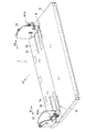
図1に示すように、本実施の形態に係る給紙装置1は、用紙を載置する給紙台2と、給紙方向a1に対して垂直な紙幅方向b1,b2の用紙位置を規制する一対の給紙フェンス10を備えている。
<Overall configuration of paper feeder>
As shown in FIG. 1, the
給紙台2は、樹脂等で成形され、給紙フェンス10を紙幅方向b1,b2に移動させる際の案内溝3a、3bが形成されている。
The paper feed table 2 is formed of resin or the like, and
また、案内溝3aに沿って目盛り4が刻設され、位置合わせの基準とされている。
Further, a scale 4 is engraved along the
各給紙フェンス10は、給紙フェンス10を所望の位置で固定する給紙フェンスロック機構A1a、A1bを備えている。
Each of the
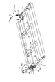
また、図1〜図5等に示すように、給紙装置1は、給紙フェンス10を起立状態で支持すると共に、紙幅方向b1、b2に摺動されるスライダー部材11と、スライダー部材11が有する挿通孔11aを介して挿通され、スライダー部材11を紙幅方向b1、b2に摺動可能に支持するスライド軸20とを備えている。
As shown in FIGS. 1 to 5 and the like, the
給紙フェンスロック機構A1a、A1bは、スライダー部材11の給紙フェンス10から離間する位置に設けられている。
The paper feed fence lock mechanisms A1a and A1b are provided at positions away from the
スライダー部材11は、図4、図5等に示すように、挿通孔11aが穿設された筒状部11Aと、この筒状部11Aの一端側(図4、図5上では左端側)から上方に延設される垂直部11Bと、この垂直部11Bからさらに上方に延設され、後述するビス19を介して給紙フェンス10と係合される係合部11Cとを備えている。
As shown in FIGS. 4 and 5, the
なお、スライダー部材11の垂直部11Bには、給紙フェンスロック機構A1a、A1bの一部を構成する凸部11b(詳細については後述する)が形成されている。
The
スライダー部材11はアルミダイキャスト或いは樹脂等で成形され、挿通孔11aの内径は、スライド軸20の直径よりも若干大きく形成されている。
The
給紙台2の内部には、図2に示すように、金属板等で構成されるフレーム50が設けられ、スライド軸20はフレーム50の一部を構成する桁材51、52の間に固定されている。
As shown in FIG. 2, a
スライド軸20は例えば直径8mm程度のステンレス製の棒材で構成される。
The
そして、スライダー部材11の筒状部11Aが有する挿通孔11aに、このスライド軸20が挿通されている。
The
これにより、スライダー部材11は、挿通孔11aに挿通されたスライド軸20に沿って紙幅方向b1、b2にスムーズに摺動可能とされる。そして、このスライダー部材11の摺動に伴って給紙フェンス10も紙幅方向b1,b2(図1参照)に移動される。従って、給紙フェンスロック機構A1a、A1bによるロック力が解除された状態において、紙幅に合わせた位置に給紙フェンス10を移動させることが可能となる。
Thereby, the
なお、本実施の形態において、図4,図5等に示すように、スライダー部材11の係合部11Cは、後述する摘み部17と共に、ビス19によって給紙フェンス10に螺合されるようになっている。
In this embodiment, as shown in FIGS. 4 and 5, etc., the engaging
また、給紙フェンスロック機構A1a、A1bは、スライド軸20に遊嵌される孔部12cを有する規制部材12を備え、用紙位置を規制する規制時において規制部材12が有する孔部12cの角張った内周部(周縁部)12d、12eをスライド軸20の表面に所定の押圧力F1、F2(F1’、F2’)で押圧させ(図6(a)、(b)参照)、用紙位置を変更する規制解除時において押圧力を解除させるようになっている。押圧力F1、F2(F1’、F2’)等の詳細については後述する。
Further, the paper feed fence lock mechanisms A1a and A1b are provided with a regulating
〈給紙フェンスロック機構の具体的構成〉
次に、図3〜図5等を参照して、給紙フェンスロック機構A1a、A1bの具体的構成について説明する。
<Specific configuration of paper feed fence lock mechanism>
Next, a specific configuration of the paper feed fence lock mechanisms A1a and A1b will be described with reference to FIGS.
なお、本実施の形態における給紙フェンスロック機構A1a、A1bは、同じ構造を備えている。以降は、代表して給紙フェンスロック機構A1aについて詳細を説明する。 The paper feed fence lock mechanisms A1a and A1b in the present embodiment have the same structure. Hereinafter, as a representative, details of the paper feed fence lock mechanism A1a will be described.
給紙フェンスロック機構A1aは、SECC(電気亜鉛めっき鋼板)等を折り曲げ加工して形成される板状の規制部材12と、スライダー部材11が有する筒状部11Aの上下方向の一端側(図上は下端側)に固定され、規制部材12の上下方向の一端部(図上は下端部)12aが係合されて規制部材12が回動される際の支点となる係合孔13aを有する支点板13と、支点板13およびスライド軸20の上下方向の他端側(図上は上方)に位置し、用紙位置を規制する規制時において規制部材12を給紙フェンス10に近接する方向に付勢するバネ部材としてのコイルスプリング14と、規制部材12の上下方向の他端側(図上は上端側)12aに設けられ、コイルスプリング14の付勢力に抗して給紙フェンス10から離間する方向に、規制部材12を支点板13の係合孔13aを支点として回動させるレバー部材16とを備えている。
The paper feed fence lock mechanism A1a includes a plate-
本実施の形態において、レバー部材16は、図4、図5等に示すように、正面から観た断面形状が略L形とされる樹脂成形品等で形成される。
In the present embodiment, the
また、スライダー部材11の垂直部11Bにおいて、給紙フェンス10側とは反対側の面には、スライド軸20と平行となるように突出された凸部11aが一体的に設けられている。また、規制部材12には、凸部11aが挿通される挿通孔12fが形成されている(図4、図5参照)。
Further, in the
凸部11aには、規制部材12が挿通孔12fを介して係合され、規制部材12をスライダー部材11側に付勢するようにコイルスプリング14が凸部11aに挿通され、コイルスプリング14を凸部11aに係止する係止部材としてのEリング(E型止め輪)が凸部11aの端部に係合されている。
The restricting
また、レバー部材16と対向する位置にあって、規制部材12を給紙フェンス10から離間する方向に回動させる際に、レバー部材16と共に操作者の指で摘まれる金属板等の折り曲げ加工品等で形成される摘み部17が設けられている。
Further, when the regulating
図4に示すように、本実施の形態において、摘み部17は、ビス19によって、スライダー部材11の係合部11Cおよび給紙フェンス10に固定されている。このビス19によって、スライダー部材11と給紙フェンス10とが一体的に固定されている。
As shown in FIG. 4, in the present embodiment, the
また、前出の支点板13は、ビス18によって、スライダー部材11に固定されている。さらに、前出のレバー部材16は、ビス21によって、規制部材12の上端において水平方向に延設される上端部12bに固定されている。
The
〈給紙フェンスロック機構の動作〉
次に、図6〜図8等を参照して、上記構成の給紙フェンスロック機構A1a、A1bの動作について説明する。
<Operation of feeding fence lock mechanism>
Next, the operation of the paper feed fence locking mechanisms A1a and A1b configured as described above will be described with reference to FIGS.
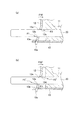
まず、図6を参照して、給紙フェンスロック機構A1a、A1bのロック状態について説明する。 First, the locked state of the paper feed fence lock mechanisms A1a and A1b will be described with reference to FIG.
ここで、図6は、本実施形態に係る給紙装置1が備える給紙フェンスロック機構A1a、A1bの動作を示す説明図であり、図6(a)はコイルスプリング14の付勢力のみの場合の動作、図6(b)は給紙フェンス10を介して用紙からの押圧力F3が加わった場合の動作を示す。
Here, FIG. 6 is an explanatory view showing the operation of the paper feed fence lock mechanisms A1a and A1b provided in the
図6(a)に示すように、図4、図5等に示すコイルスプリング14の付勢力のみが規制部材12に加わる場合には、この付勢力により、支点板13の係合孔13aを支点に規制部材12を給紙フェンス10側に傾倒させる回動力F10が発生する。
As shown in FIG. 6A, when only the urging force of the
これにより、規制部材12が有する孔部12cの角張った内周部(周縁部)12d、12eが、スライド軸20の表面に接触される。そして、回動力F10により、内周部(周縁部)12d、12eとスライド軸20の表面との接触部には、ベクトルF1、F2によって示される押圧力が加わる。
As a result, the angular inner peripheral portions (peripheral portions) 12 d and 12 e of the
この押圧力(ベクトルF1、F2)に伴って発生する内周部(周縁部)12d、12eとスライド軸20の表面との接触部における摩擦力により、給紙フェンス10はロックされた状態となる。
The
次に、図6(b)を参照して、給紙フェンス10を介して用紙からの押圧力F3が加わった場合の動作について説明する。
Next, with reference to FIG. 6B, the operation when the pressing force F3 from the sheet is applied via the
具体的には、例えばA3サイズ等の大判用紙を給紙台2(図1参照)にセットする際には、用紙重量が重いため、何回かに分けて用紙束を積載する場合がある。その場合に、各々の用紙一束ごとに積載端面がずれ易く、用紙端面を叩いて端面を揃える必要がある。 Specifically, for example, when a large sheet of A3 size or the like is set on the sheet feed tray 2 (see FIG. 1), the sheet weight may be heavy, and the sheet bundle may be stacked several times. In that case, the stacking end face tends to be displaced for each bundle of sheets, and it is necessary to hit the end face of the sheets and align the end faces.
そして、給紙フェンス10側に用紙束を押す力が加わった際に、給紙フェンス10と共にスライダー部材11および支点板13に用紙から離間される方向に押圧力F3が発生する。
When a force pushing the sheet bundle is applied to the
この押圧力F3により、支点板13の係合孔13aを支点に規制部材13を給紙フェンス10側に傾倒させる回動力F10’が発生する。
The pressing force F3 generates a rotational force F10 'that tilts the regulating
これにより、規制部材12が有する孔部12cの角張った内周部(周縁部)12d、12eが、スライド軸20の表面により強く押圧される。即ち、回動力F10’により、内周部(周縁部)12d、12eとスライド軸20の表面との接触部には、ベクトルF1’、F2’によって示される押圧力が加わる。
Accordingly, the angular inner peripheral portions (peripheral portions) 12 d and 12 e of the
この押圧力(ベクトルF1’、F2’)に伴って発生する内周部(周縁部)12d、12eとスライド軸20の表面との接触部におけるより強い摩擦力により、給紙フェンス10をより強固にロックされた状態とすることができる。
Due to the stronger frictional force at the contact portion between the inner peripheral portions (peripheral portions) 12d, 12e and the surface of the
次に、図7および図8を参照して、実施形態に係る給紙装置1が備える給紙フェンスロック機構A1a、A1bのロックを解除する際の操作について説明する。
Next, with reference to FIG. 7 and FIG. 8, an operation for releasing the lock of the paper feed fence lock mechanisms A1a and A1b included in the
給紙フェンスロック機構A1a、A1bのロックを解除する際には、図7に示すように、レバー部材16を給紙フェンス10から離間する方向に手動で動かすように操作する。
When unlocking the paper feed fence lock mechanisms A1a and A1b, the
実際には、例えば、図7上、摘み部17の左端側に左手の人差し指を触れさせ、親指でレバー部材16を摘み部17側に寄せるように摘む力F4を加えることで、レバー部材16を容易に動かすことができる。
Actually, for example, in FIG. 7, the
そして、図8に示すように、支点板13の係合孔13aを支点に規制部材13を給紙フェンス10から離間する方向に傾倒させる力F5が加えられる。
Then, as shown in FIG. 8, a force F <b> 5 is applied to tilt the regulating
これにより、規制部材12が有する孔部12cの角張った内周部(周縁部)12d、12eと、スライド軸20の表面との接触状態が解除される。従って、図7のように、レバー部材16を摘んだ状態を保持した状態で、給紙フェンス10を紙幅方向b1(b2)に移動させて、用紙の幅に合った位置にスムーズに移動させることができる。
Thereby, the contact state between the angular inner peripheral portions (peripheral portions) 12d and 12e of the
このように、本実施の形態に係る給紙装置1が備える給紙フェンスロック機構A1a、A1bによれば、偏芯カム等を用いたロック機構を備える給紙装置に比してロックさせる際のレバーの操作力が大きくなることを回避でき、給紙フェンスのロック力を高めつつ、給紙フェンスの位置を変更する際の操作性を向上させることができる。
As described above, according to the paper feed fence lock mechanisms A1a and A1b provided in the
以上本発明者によってなされた発明を実施の形態に基づき具体的に説明したが、本明細書で開示された実施の形態はすべての点で例示であって開示された技術に限定されるものではないと考えるべきである。すなわち、本発明の技術的な範囲は、前記の実施の形態における説明に基づいて制限的に解釈されるものでなく、あくまでも特許請求の範囲の記載にしたがって解釈すべきであり、特許請求の範囲の記載技術と均等な技術および特許請求の範囲内でのすべての変更が含まれる。 Although the invention made by the present inventor has been specifically described based on the embodiments, the embodiments disclosed herein are illustrative in all respects and are not limited to the disclosed technology. Should not be considered. That is, the technical scope of the present invention should not be construed restrictively based on the description in the above embodiment, but should be construed according to the description of the scope of claims. All the modifications within the scope of the claims and the equivalent technique to the described technique are included.
例えば、本実施の形態では、図1に示すように、左右両側に給紙フェンスロック機構A1a、A1bを備えた給紙フェンス10を設ける場合について示したが、これに限られず、左右の何れか一方の給紙フェンス10のみに給紙フェンスロック機構を設け、他方は固定式の給紙フェンスとしても良い。
For example, in the present embodiment, as shown in FIG. 1, the case where the
また、図1に示すように、給紙台2を備えた、いわゆる手差し式の給紙装置に限らず、トレー式の給紙装置において給紙フェンスロック機構A1a、A1bを備えた給紙フェンス10を設けるようにしても良い。
Further, as shown in FIG. 1, the
また、スライド軸20の表面を粗面化したり、複数の溝を刻設するなどして、規制部材12が有する孔部12cの内周部(周縁部)12d、12eが接触した際の摩擦力を高めるようにしても良い。
Further, the frictional force when the inner peripheral portions (peripheral portions) 12d and 12e of the
A1a、A1b…給紙フェンスロック機構
1…給紙装置
2…給紙台
3a、3b…案内溝
4…目盛り
10…給紙フェンス
11…スライダー部材
11A…筒状部
11B…垂直部
11C…係合部
11a…凸部
11a…挿通孔
12…規制部材
12c…孔部
12d…内周部(周縁部)
12f…挿通孔
13…支点板
13a…係合孔
14…コイルスプリング(バネ部材)
16…レバー部材
17…摘み部
18、19、21…ビス
20…スライド軸
50…フレーム
51…桁材
F1、F2(F1’、F2’)、F3…押圧力
F10…回動力
A1a, A1b ... Feed
12f ...
DESCRIPTION OF
Claims (2)
前記給紙フェンスを起立状態で支持すると共に、前記紙幅方向に摺動されるスライダー部材と、
前記スライダー部材が有する挿通孔を介して挿通され、該スライダー部材を前記紙幅方向に摺動可能に支持するスライド軸と、
前記スライド軸に遊嵌される孔部を有し、前記スライダー部材の前記給紙フェンスから用紙の幅方向に離間する位置に設けられる板状の規制部材を有する給紙フェンスロック機構と
を備え、
前記給紙フェンスロック機構は、
前記スライダー部材の上下方向の一端側に固定され、前記規制部材の上下方向の一端部が係合されて該規制部材が回動される際の支点となる係合孔を有する支点板と、
前記支点板および前記スライド軸の上下方向の他端側に位置し、前記規制部材を前記給紙フェンスに近接する方向に所定の付勢力を付加するバネ部材と
を備え、
前記給紙フェンスロック機構は、前記用紙位置を規制する規制時において前記バネ部材により前記規制部材に加わる前記所定の付勢力によって、当該規制部材が前記支点板の前記係合孔を支点として前記給紙フェンス側に向かって傾倒することで、前記孔部の内周部の一部が前記スライド軸の表面に押圧されて当該スライダー部材の前記スライド軸に沿った動きを規制し、
前記用紙位置を変更する規制解除時において前記付勢力を解除させて当該スライダー部材の前記スライド軸に沿った動きの規制を解除することを特徴とする給紙装置。 In a paper feeding device having a paper feeding table for placing paper and a paper feeding fence for regulating the paper position in the paper width direction perpendicular to the paper feeding direction,
A slider member that supports the paper feed fence in an upright state and is slid in the paper width direction;
A slide shaft that is inserted through an insertion hole of the slider member and supports the slider member slidably in the paper width direction;
A paper feed fence lock mechanism having a plate-like restricting member provided in a position spaced apart from the paper feed fence of the slider member in the width direction of the paper, having a hole portion loosely fitted to the slide shaft,
The paper feed fence lock mechanism is
A fulcrum plate fixed to one end side in the vertical direction of the slider member, and having an engagement hole serving as a fulcrum when the one end portion in the vertical direction of the regulating member is engaged and the regulating member is rotated;
A spring member that is positioned on the other end side in the vertical direction of the fulcrum plate and the slide shaft, and that applies a predetermined urging force to the regulating member in a direction close to the paper feed fence;
With
The feeding fence lock mechanism is configured to cause the regulating member to use the engagement hole of the fulcrum plate as a fulcrum by the predetermined urging force applied to the regulating member by the spring member at the time of regulating the paper position. By tilting toward the paper fence side , a part of the inner peripheral portion of the hole is pressed against the surface of the slide shaft to regulate the movement of the slider member along the slide shaft,
A sheet feeding device that releases the urging force and releases the restriction of the movement of the slider member along the slide shaft when the restriction for changing the paper position is released.
前記規制部材の上下方向の他端側に設けられ、前記バネ部材の前記付勢力に抗して前記給紙フェンスから離間する方向に、前記規制部材を前記支点板の係合孔を支点として回動させるレバー部材
を備えることを特徴とする請求項1に記載の給紙装置。 The paper feed fence lock mechanism is
Provided on the other end in the vertical direction of the restricting member, the restricting member is rotated about the engaging hole of the fulcrum plate in a direction away from the paper feed fence against the biasing force of the spring member. Lever member to be moved
The sheet feeding device according to claim 1, further comprising:
Priority Applications (3)
| Application Number | Priority Date | Filing Date | Title |
|---|---|---|---|
| JP2013002548A JP6055314B2 (en) | 2013-01-10 | 2013-01-10 | Paper feeder |
| CN201310741593.2A CN103922162B (en) | 2013-01-10 | 2013-12-27 | Paper feeding device |
| US14/146,247 US8925915B2 (en) | 2013-01-10 | 2014-01-02 | Sheet supply device |
Applications Claiming Priority (1)
| Application Number | Priority Date | Filing Date | Title |
|---|---|---|---|
| JP2013002548A JP6055314B2 (en) | 2013-01-10 | 2013-01-10 | Paper feeder |
Publications (2)
| Publication Number | Publication Date |
|---|---|
| JP2014133630A JP2014133630A (en) | 2014-07-24 |
| JP6055314B2 true JP6055314B2 (en) | 2016-12-27 |
Family
ID=51060407
Family Applications (1)
| Application Number | Title | Priority Date | Filing Date |
|---|---|---|---|
| JP2013002548A Active JP6055314B2 (en) | 2013-01-10 | 2013-01-10 | Paper feeder |
Country Status (3)
| Country | Link |
|---|---|
| US (1) | US8925915B2 (en) |
| JP (1) | JP6055314B2 (en) |
| CN (1) | CN103922162B (en) |
Families Citing this family (4)
| Publication number | Priority date | Publication date | Assignee | Title |
|---|---|---|---|---|
| JP6167091B2 (en) * | 2014-10-06 | 2017-07-19 | 京セラドキュメントソリューションズ株式会社 | Paper feeding device and image forming apparatus |
| JP7098407B2 (en) * | 2018-04-27 | 2022-07-11 | キヤノン株式会社 | Sheet accommodating device and image forming device |
| JP7420573B2 (en) | 2020-01-30 | 2024-01-23 | 理想科学工業株式会社 | seat support device |
| CN114263326B (en) * | 2021-12-29 | 2024-04-19 | 中联重科新材料科技有限公司 | Terrace isolation system and construction method thereof |
Family Cites Families (15)
| Publication number | Priority date | Publication date | Assignee | Title |
|---|---|---|---|---|
| JPS55176242U (en) * | 1979-06-07 | 1980-12-17 | ||
| JPS60109944U (en) * | 1983-12-28 | 1985-07-25 | 沖電気工業株式会社 | Platen with sprocket wheel |
| JPS6332844U (en) * | 1986-08-14 | 1988-03-03 | ||
| JPS6365631U (en) * | 1986-10-21 | 1988-04-30 | ||
| US5170682A (en) * | 1988-08-19 | 1992-12-15 | Petersen Manufacturing Co., Inc. | Quick action bar clamp |
| US5022137A (en) * | 1988-08-19 | 1991-06-11 | Petersen Manufacturing Co., Inc. | Method of operating a quick-action bar clamp |
| JPH05319585A (en) * | 1992-05-14 | 1993-12-03 | Ricoh Co Ltd | Paper feeding tray |
| US5194431A (en) | 1992-07-08 | 1993-03-16 | Wisconsin Alumni Research Foundation | 24-cyclopropane vitamin D derivatives |
| JP2582470Y2 (en) * | 1993-03-16 | 1998-10-08 | 株式会社セコニック | Large capacity paper feeder |
| EP0663624A3 (en) * | 1994-01-14 | 1996-03-20 | Mita Industrial Co Ltd | Paper regulating mechanism and paper cassette. |
| JP2002362760A (en) * | 2001-04-06 | 2002-12-18 | Ricoh Co Ltd | Paper feeder |
| KR100423465B1 (en) * | 2002-04-11 | 2004-03-18 | 삼성전자주식회사 | apparatus for guiding a printing paper in an office machine |
| JP2008297040A (en) * | 2007-05-30 | 2008-12-11 | Kyocera Mita Corp | Paper feed unit of image forming device |
| JP2010052886A (en) * | 2008-08-28 | 2010-03-11 | Kyocera Mita Corp | Paper feeding cassette |
| JP5219720B2 (en) * | 2008-10-01 | 2013-06-26 | キヤノン株式会社 | Sheet feeding apparatus and image forming apparatus |
-
2013
- 2013-01-10 JP JP2013002548A patent/JP6055314B2/en active Active
- 2013-12-27 CN CN201310741593.2A patent/CN103922162B/en active Active
-
2014
- 2014-01-02 US US14/146,247 patent/US8925915B2/en active Active
Also Published As
| Publication number | Publication date |
|---|---|
| CN103922162B (en) | 2016-05-11 |
| JP2014133630A (en) | 2014-07-24 |
| US20140191464A1 (en) | 2014-07-10 |
| CN103922162A (en) | 2014-07-16 |
| US8925915B2 (en) | 2015-01-06 |
Similar Documents
| Publication | Publication Date | Title |
|---|---|---|
| JP6055314B2 (en) | Paper feeder | |
| CN107458896B (en) | Sheet feeding device and image forming apparatus | |
| JP4713451B2 (en) | Sliding mechanism, paper guide, paper stacking device, manual paper feed tray, and image forming apparatus | |
| US8430399B1 (en) | Paper tray | |
| US7634212B2 (en) | Position adjustable control panel for image forming device | |
| JP6269611B2 (en) | Page floating suppression device, page turning device, and page turning method | |
| JP4997125B2 (en) | Printer | |
| US8500058B2 (en) | Paper roll fixing device of printer | |
| JP2006206319A (en) | Paper feeder and image forming device having the paper feeder | |
| JP2010168164A (en) | Paper feeding cassette | |
| JP4967042B2 (en) | Operating device, information processing apparatus, and image forming apparatus | |
| US7543812B2 (en) | Media registration devices | |
| JP2007153458A (en) | Paper feeding cassette | |
| JP5306504B2 (en) | Image forming apparatus | |
| JP4045574B2 (en) | Paper ruler | |
| JP2019144466A (en) | Image forming apparatus | |
| JP2008135095A (en) | Guide device of optical pickup | |
| JP2012233940A (en) | Image forming device | |
| JP2016101997A (en) | Paper feeder and image forming device | |
| JP2017043446A (en) | Paper discharge device | |
| JP2005219933A (en) | Printed matter storage device | |
| JP2015163553A (en) | Sheet feeding device and image forming system | |
| JP2010100367A (en) | Paper feeding cassette, paper feeder and image forming device | |
| JP2018016426A (en) | Sheet storage device and image forming apparatus | |
| JP2000044077A (en) | Paper sheet housing device |
Legal Events
| Date | Code | Title | Description |
|---|---|---|---|
| A621 | Written request for application examination |
Free format text: JAPANESE INTERMEDIATE CODE: A621 Effective date: 20151102 |
|
| A977 | Report on retrieval |
Free format text: JAPANESE INTERMEDIATE CODE: A971007 Effective date: 20160727 |
|
| A131 | Notification of reasons for refusal |
Free format text: JAPANESE INTERMEDIATE CODE: A131 Effective date: 20160802 |
|
| A521 | Request for written amendment filed |
Free format text: JAPANESE INTERMEDIATE CODE: A523 Effective date: 20160927 |
|
| TRDD | Decision of grant or rejection written | ||
| A01 | Written decision to grant a patent or to grant a registration (utility model) |
Free format text: JAPANESE INTERMEDIATE CODE: A01 Effective date: 20161115 |
|
| A61 | First payment of annual fees (during grant procedure) |
Free format text: JAPANESE INTERMEDIATE CODE: A61 Effective date: 20161202 |
|
| R150 | Certificate of patent or registration of utility model |
Ref document number: 6055314 Country of ref document: JP Free format text: JAPANESE INTERMEDIATE CODE: R150 |
|
| R250 | Receipt of annual fees |
Free format text: JAPANESE INTERMEDIATE CODE: R250 |
|
| R250 | Receipt of annual fees |
Free format text: JAPANESE INTERMEDIATE CODE: R250 |
|
| R250 | Receipt of annual fees |
Free format text: JAPANESE INTERMEDIATE CODE: R250 |
|
| R250 | Receipt of annual fees |
Free format text: JAPANESE INTERMEDIATE CODE: R250 |
|
| R250 | Receipt of annual fees |
Free format text: JAPANESE INTERMEDIATE CODE: R250 |