JP6052704B2 - INPUT DEVICE, INPUT OPERATION ANALYSIS METHOD, INPUT OPERATION ANALYSIS PROGRAM - Google Patents
INPUT DEVICE, INPUT OPERATION ANALYSIS METHOD, INPUT OPERATION ANALYSIS PROGRAM Download PDFInfo
- Publication number
- JP6052704B2 JP6052704B2 JP2012154605A JP2012154605A JP6052704B2 JP 6052704 B2 JP6052704 B2 JP 6052704B2 JP 2012154605 A JP2012154605 A JP 2012154605A JP 2012154605 A JP2012154605 A JP 2012154605A JP 6052704 B2 JP6052704 B2 JP 6052704B2
- Authority
- JP
- Japan
- Prior art keywords
- tip
- bending
- piezoelectric
- handle shaft
- sensor
- Prior art date
- Legal status (The legal status is an assumption and is not a legal conclusion. Google has not performed a legal analysis and makes no representation as to the accuracy of the status listed.)
- Expired - Fee Related
Links
- 238000004458 analytical method Methods 0.000 title claims description 23
- PWPJGUXAGUPAHP-UHFFFAOYSA-N lufenuron Chemical compound C1=C(Cl)C(OC(F)(F)C(C(F)(F)F)F)=CC(Cl)=C1NC(=O)NC(=O)C1=C(F)C=CC=C1F PWPJGUXAGUPAHP-UHFFFAOYSA-N 0.000 title 1
- 238000005452 bending Methods 0.000 claims description 131
- 230000006870 function Effects 0.000 claims description 63
- 239000013598 vector Substances 0.000 claims description 43
- 239000010408 film Substances 0.000 claims description 32
- 239000010409 thin film Substances 0.000 claims description 20
- 238000009826 distribution Methods 0.000 claims description 15
- 241000870659 Crassula perfoliata var. minor Species 0.000 description 48
- 238000001514 detection method Methods 0.000 description 35
- 238000003860 storage Methods 0.000 description 34
- 238000000034 method Methods 0.000 description 32
- 238000004891 communication Methods 0.000 description 30
- 238000006073 displacement reaction Methods 0.000 description 29
- 239000003990 capacitor Substances 0.000 description 23
- 239000000463 material Substances 0.000 description 23
- 238000010586 diagram Methods 0.000 description 21
- 210000004209 hair Anatomy 0.000 description 19
- 230000000694 effects Effects 0.000 description 14
- 239000003973 paint Substances 0.000 description 10
- 230000015572 biosynthetic process Effects 0.000 description 9
- 238000003786 synthesis reaction Methods 0.000 description 9
- 238000004040 coloring Methods 0.000 description 8
- 239000003921 oil Substances 0.000 description 8
- 238000010422 painting Methods 0.000 description 6
- 230000003321 amplification Effects 0.000 description 5
- 238000003199 nucleic acid amplification method Methods 0.000 description 5
- 238000006243 chemical reaction Methods 0.000 description 4
- 230000002093 peripheral effect Effects 0.000 description 4
- 239000002033 PVDF binder Substances 0.000 description 3
- 238000004519 manufacturing process Methods 0.000 description 3
- 229920002981 polyvinylidene fluoride Polymers 0.000 description 3
- HBBGRARXTFLTSG-UHFFFAOYSA-N Lithium ion Chemical compound [Li+] HBBGRARXTFLTSG-UHFFFAOYSA-N 0.000 description 2
- 230000001133 acceleration Effects 0.000 description 2
- 230000005540 biological transmission Effects 0.000 description 2
- 239000003086 colorant Substances 0.000 description 2
- 239000004973 liquid crystal related substance Substances 0.000 description 2
- 229910001416 lithium ion Inorganic materials 0.000 description 2
- 230000007935 neutral effect Effects 0.000 description 2
- 238000003825 pressing Methods 0.000 description 2
- 229920005989 resin Polymers 0.000 description 2
- 239000011347 resin Substances 0.000 description 2
- 230000035945 sensitivity Effects 0.000 description 2
- 239000000758 substrate Substances 0.000 description 2
- 230000006399 behavior Effects 0.000 description 1
- 230000001680 brushing effect Effects 0.000 description 1
- 238000004364 calculation method Methods 0.000 description 1
- 230000007423 decrease Effects 0.000 description 1
- 238000000151 deposition Methods 0.000 description 1
- 238000005516 engineering process Methods 0.000 description 1
- 239000000835 fiber Substances 0.000 description 1
- 239000011521 glass Substances 0.000 description 1
- 230000012447 hatching Effects 0.000 description 1
- 238000005304 joining Methods 0.000 description 1
- 238000010030 laminating Methods 0.000 description 1
- 229910052751 metal Inorganic materials 0.000 description 1
- 239000002184 metal Substances 0.000 description 1
- 230000003287 optical effect Effects 0.000 description 1
- 229920000642 polymer Polymers 0.000 description 1
- 239000002952 polymeric resin Substances 0.000 description 1
- 229920002379 silicone rubber Polymers 0.000 description 1
- 230000002194 synthesizing effect Effects 0.000 description 1
- 229920003002 synthetic resin Polymers 0.000 description 1
Images


Landscapes
- User Interface Of Digital Computer (AREA)
Description
本発明は、タッチパネルを備えた入力装置、および、入力操作解析方法、入力操作解析プログラムに関する。 The present invention relates to an input device including a touch panel, an input operation analysis method, and an input operation analysis program.
近年、スマートフォン(高機能携帯電話機)やタブレット型の情報端末のような、いわゆるタッチパネル方式の入力装置を備えた電子機器が急速に普及している。このような入力装置を備えた電子機器は従来から知られており、例えば金融機関の現金自動預け払い機(ATM)や、自動券売機、カーナビゲーションシステム、携帯ゲーム機、パーソナルコンピュータの周辺機器として使用されるペンタブレット等、広範な製品分野において使用されている。 In recent years, electronic devices including a so-called touch panel type input device such as a smartphone (high-performance mobile phone) and a tablet-type information terminal have been rapidly spread. Electronic devices equipped with such an input device have been known in the past. For example, as a peripheral device of an automatic teller machine (ATM), automatic ticket vending machine, car navigation system, portable game machine, personal computer of a financial institution. It is used in a wide range of product fields such as used pen tablets.
タッチパネル方式の入力装置は、概略、液晶や有機EL等の表示装置と、その前面(視野側)に配置された、または、表示装置と一体的に形成されたタッチセンサーと、を有し、ユーザが表示装置に表示された文字情報や画像を認識して、任意の表示領域にスタイラスペンや指を接触させることにより、所望の入力操作を行うことができる。 A touch panel type input device generally includes a display device such as a liquid crystal display or an organic EL, and a touch sensor disposed on the front surface (view side) or integrally formed with the display device. Recognizes character information and images displayed on the display device, and makes a desired input operation by bringing a stylus pen or a finger into contact with an arbitrary display area.
ここで、タッチパネルへの入力方法は大別して指先等を使用する方式と、入力ペンを使用する方式が知られている。前者においては、タッチパネルの背面に表示された画像等を認識し、所望の機能を実現するためのアイコン画像等を直感的に選択して入力する場合に適している。一方、後者においては、文字入力や描画入力等、細かな入力作業を行う場合に適している。さらに、入力ペンを用いてタッチパネルに入力を行う場合、入力の強さ(いわゆる筆圧)を検出することができる入力装置も知られている。 Here, the input method to the touch panel is roughly classified into a method using a fingertip or the like and a method using an input pen. The former is suitable for recognizing an image or the like displayed on the back of the touch panel and intuitively selecting and inputting an icon image or the like for realizing a desired function. On the other hand, the latter is suitable for performing fine input operations such as character input and drawing input. Furthermore, an input device that can detect the input strength (so-called writing pressure) when performing input on a touch panel using an input pen is also known.
なお、入力ペンを用いてタッチパネルに入力操作を行う技術については、例えば特許文献1や特許文献2に記載されている。これらの特許文献には、硬質のペン先を備えたスタイラスペン(入力ペン)において、ペン本体の内部に筆圧を検出するための圧電素子を備えた構成が開示されている。
For example,
上述したような入力ペンを使用した入力方式において、硬質のペン先を備えた入力ペンでの操作感は、実際に紙やキャンバス等に絵筆や毛筆等を使って絵や図形、文字等を描く際の操作感とは異なっている。このような操作感の差異は、主に、入力ペンのタッチパネル表面における反力や摩擦力の相違に起因するものである。そのため、タッチパネルを備えた電子機器に対して、上述したような入力ペンを用いて絵や図形、文字等を手書きで入力する際に、ユーザは違和感を覚えることが多いという問題を有している。 In the input method using the input pen as described above, the operation feeling with the input pen having a hard pen tip is actually drawn with a paintbrush or brush on a paper or canvas etc. It is different from the operation feeling. Such a difference in operational feeling is mainly caused by a difference in reaction force and frictional force on the touch panel surface of the input pen. Therefore, there is a problem that a user often feels uncomfortable when inputting a picture, a figure, a character, or the like by hand using an input pen as described above for an electronic device having a touch panel. .
なお、近年、絵筆の穂先の形状に成形したシリコンゴム上に静電気植毛技術を用いて加工したペン先を備えた入力ペン(筆型デバイス)により、穂先の撓りを検出する方式が提案されているが、その操作感は実際の絵筆と同等のレベルを実現するには至っていない。 In recent years, a method has been proposed for detecting the deflection of the tip of a brush using an input pen (brush-type device) having a pen tip processed using electrostatic flocking technology on silicon rubber molded into the shape of the tip of a paint brush. However, the feeling of operation has not yet reached the same level as an actual paint brush.
そこで、本発明は、上述した問題点に鑑み、タッチパネル表面への入力操作において、実際に絵筆や毛筆等を用いて絵や文字等を描く際と同等の操作感を実現するとともに、筆使いや筆運びに応じた筆の特徴を再現することができる入力装置、および、入力操作解析方法、入力操作解析プログラムを提供することを目的とする。 Therefore, in view of the above-described problems, the present invention realizes an operation feeling equivalent to that when actually drawing a picture, a character, or the like using a paintbrush or a brush in an input operation on the touch panel surface. It is an object of the present invention to provide an input device, an input operation analysis method, and an input operation analysis program that can reproduce the characteristics of the brush according to the brush stroke.
本発明に係る入力装置は、
柄軸と、
前記柄軸の先端部に設けられ、当該柄軸の先端部の撓りに応じて電圧を出力する複数のセンサーであって、かつ、それぞれが平面状の部分を有する圧電フィルムを含み、各圧電フィルムの前記平面状の部分が互いに交差する向きに配置されている複数のセンサーと、
前記複数のセンサーが出力した複数の電圧に基づいて前記柄軸の先端部の撓り状態を取得する制御部と、
を備える
ことを特徴とする。
An input device according to the present invention includes:
The handle axis,
Each of the piezoelectric elements includes a plurality of sensors that are provided at the tip of the handle shaft and output a voltage according to the bending of the tip of the handle shaft , each having a planar portion. A plurality of sensors arranged in a direction in which the planar portions of the film intersect each other ;
A control unit for acquiring a bending state of a tip portion of the handle shaft based on a plurality of voltages output by the plurality of sensors;
It is characterized by providing.
本発明に係る入力操作解析方法は、
柄軸と、前記柄軸の先端部に設けられ、当該柄軸の先端部の撓りに応じて電圧を出力するセンサーと、を備える入力装置における入力操作解析方法であって、
前記センサーは、それぞれが平面状の部分を有する圧電フィルムを含み、各圧電フィルムの前記平面状の部分が互いに交差する向きに配置されている複数のセンサーを含み、
前記複数のセンサーのそれぞれにより出力された各電圧に応じた前記柄軸の先端部の前記撓り状態を示す各ベクトルを合成して複数の合成ベクトルを生成し、生成した前記複数の合成ベクトルに基づいて、前記柄軸の先端部の撓り量および撓り方向を、撓り状態として取得する、
ことを特徴とする。
The input operation analysis method according to the present invention includes:
And handle shaft, provided at the distal end portion of the handle shaft, an input operation analyzing method in the input device comprising a sensor for outputting a voltage in accordance with the flexure of the tip portion of the handle shaft,
The sensor includes a plurality of sensors each including a piezoelectric film having a planar portion, and the planar portions of each piezoelectric film are arranged in a direction intersecting each other,
A plurality of combined vectors are generated by combining each vector indicating the bending state of the tip end portion of the handle axis corresponding to each voltage output by each of the plurality of sensors, and the generated plurality of combined vectors Based on the bending amount and the bending direction of the tip end portion of the handle shaft as a bending state,
It is characterized by that.
本発明に係る入力操作解析プログラムは、
柄軸と、前記柄軸の先端部に設けられ、当該柄軸の先端部の撓りに応じて電圧を出力するセンサーと、を備える入力装置における入力操作の解析を、コンピュータに実行させるプログラムであって、
前記センサーは、それぞれが平面状の部分を有する圧電フィルムを含み、各圧電フィルムの前記平面状の部分が互いに交差する向きに配置されている複数のセンサーを含み、
前記コンピュータに、
前記複数のセンサーのそれぞれにより出力された各電圧に応じた前記柄軸の先端部の前記撓り状態を示す各ベクトルを合成して複数の合成ベクトルを生成させ、生成した前記複数の合成ベクトルに基づいて、前記柄軸の先端部の撓り量および撓り方向を、撓り状態として取得させる、
ことを特徴とする。
An input operation analysis program according to the present invention includes:
And handle shaft, provided at the distal end portion of the handle shaft, the analysis of the input operation in the input device comprising a sensor for outputting a voltage in accordance with the flexure of the tip portion of the handle shaft, a program for causing a computer to execute There,
The sensor includes a plurality of sensors each including a piezoelectric film having a planar portion, and the planar portions of each piezoelectric film are arranged in a direction intersecting each other,
In the computer,
Combining each vector indicating the bending state of the tip of the handle axis according to each voltage output by each of the plurality of sensors to generate a plurality of combined vectors, the generated plurality of combined vectors Based on the bending amount and the bending direction of the tip end portion of the handle shaft, as a bending state,
It is characterized by that.
本発明によれば、タッチパネル表面への入力操作において、実際に絵筆や毛筆等を用いて絵や文字等を描く際と同等の操作感を実現することができる。 According to the present invention, in the input operation on the touch panel surface, it is possible to realize an operation feeling equivalent to that when actually drawing a picture, a character, or the like using a paintbrush or a brush.
以下、本発明に係る入力装置、および、入力操作解析方法、入力操作解析プログラムについて、実施形態を示して詳しく説明する。 Hereinafter, an input device, an input operation analysis method, and an input operation analysis program according to the present invention will be described in detail with reference to embodiments.
<描画システム>
まず、本発明に係る入力装置を備えた描画システムについて説明する。ここでは、描画システムに適用されるタッチパネル型の入力装置を備えた電子機器として、タブレット型の情報端末(タブレット端末)を示すが、本発明はこれに限定されるものではない。例えば、タッチパネル型の表示装置を備えたノート型やデスクトップ型のパーソナルコンピュータに適用するものであってもよいし、ペンタブレット等の入力装置が接続されたパーソナルコンピュータに適用するものであってもよい。また、以下に示す実施形態においては、電子絵筆を用いて絵を描く(絵画を制作する)場合について説明するが、本発明はこれに限定されるものではなく、例えば、毛筆を用いて文字等を描いたり記入したりする場合であっても良好に適用することができる。
<Drawing system>
First, a drawing system provided with an input device according to the present invention will be described. Here, a tablet information terminal (tablet terminal) is shown as an electronic device including a touch panel type input device applied to a drawing system, but the present invention is not limited to this. For example, the present invention may be applied to a notebook or desktop personal computer equipped with a touch panel display device, or may be applied to a personal computer to which an input device such as a pen tablet is connected. . Further, in the embodiment described below, the case of drawing a picture using an electronic paintbrush (creating a picture) will be described, but the present invention is not limited to this, for example, a character using a brush, etc. Even when drawing or filling in, it can be applied well.
図1は、本発明が適用される描画システムの一実施形態を示す概略構成図である。図2は、本実施形態に係る描画システムに適用されるタブレット端末の一構成例を示す機能ブロック図である。 FIG. 1 is a schematic configuration diagram showing an embodiment of a drawing system to which the present invention is applied. FIG. 2 is a functional block diagram illustrating a configuration example of a tablet terminal applied to the drawing system according to the present embodiment.
本発明が適用される描画システムは、例えば図1に示すように、大別して、タッチパネル型の表示部101を備えたタブレット端末100と、一般的な絵画の制作に用いられる絵筆と同等の外観を有する電子絵筆200と、を有している。
For example, as shown in FIG. 1, the drawing system to which the present invention is applied is roughly divided into a
(タブレット端末)
タブレット端末100は、図2に示すように、概略、表示部101と、タッチパネル102と、地磁気センサー103と、記憶部104と、通信機能部105と、CPU106と、電源供給部107と、電源スイッチ108と、を有している。
(Tablet terminal)
As shown in FIG. 2, the
表示部101は、例えば液晶表示装置や有機EL表示装置等の表示装置であって、図1に示すように、矩形状を有する表示領域に、少なくともタッチパネル102への電子絵筆200による入力操作に応じた描線や彩色等が表示される。また、表示部101には、タッチパネル102への電子絵筆200による入力操作に関連する種々の設定メニューや情報が画像や文字の形態で表示される。
The display unit 101 is, for example, a display device such as a liquid crystal display device or an organic EL display device. As shown in FIG. The drawn lines and colors are displayed. The display unit 101 displays various setting menus and information related to the input operation with the
タッチパネル102は、上記表示部101の表示領域の前面(視野側)に配置され、または、当該表示部101と一体的に設けられ、電子絵筆200によるタッチパネル102への入力操作に伴う接触位置(すなわち入力位置)の座標情報が検出される。この入力位置の座標情報は、時間に関連付けられて収集され、後述するように、入力位置の変化に要した時間に基づいて、電子絵筆200の移動速度や加速度が算出される。この移動速度や加速度は、電子絵筆200の筆使いや筆運びに関連した情報として取得される。また、タッチパネル102は、例えば表示部101に表示された種々の設定メニューや情報をユーザーが認識することにより、任意の設定情報が入力される。ここで、タッチパネル102は、少なくとも電子絵筆200の入力位置を検出できるものであればよく、抵抗膜方式や静電容量方式、光学方式等、種々の方式を適用することができる。
The
地磁気センサー103は、地球の磁場の向きを計測することにより、タブレット端末100の回転方向や傾斜方向に関する情報(端末姿勢情報)を取得する。この端末姿勢情報は、後述する電子絵筆200から送信される電子絵筆200の回転方向や傾斜方向に関する情報(絵筆姿勢情報)とともに、タブレット端末100に対する電子絵筆200の相対的な回転角度や傾斜角度を算出する際に用いられる。
The geomagnetic sensor 103 acquires information (terminal attitude information) related to the rotation direction and tilt direction of the
記憶部104は、タッチパネル102により検出された入力位置の座標情報やタッチパネル102を介して入力された各種の設定情報、地磁気センサー103により取得された端末姿勢情報、後述する電子絵筆200から送信される各種データ、表示部101に表示する画像情報等を一時保存するランダムアクセスメモリ(RAM)を有する。また、記憶部104は、表示部101やタッチパネル102、地磁気センサー103、記憶部104、通信機能部105における各種機能を実行するための制御プログラムや、後述する本実施形態に係る描画制御動作を実行するための制御プログラムを格納する読み出し専用メモリ(ROM)を含むものであってもよい。CPU106は、これらの制御プログラムに従って処理を実行することにより、タブレット端末100に対する電子絵筆200の相対的な位置関係や傾斜状態等を常時把握するとともに、入力操作時における電子絵筆200の運筆状態(運筆方向やフットプリントの形状、筆圧分布)を随時判別して、当該運筆状態に応じた描線や彩色を表示部101に表示させる制御を行う。加えて、CPU106は、上記の運筆状態を判別して、電子絵筆200の運筆時の操作感を、予め入力された設定情報(操作感設定情報)に基づく所望の状態に近似させるために、穂先に所定の曲げ応力を生じさせる制御を行う。なお、これらの制御プログラムは、CPU106に予め組み込まれているものであってもよい。また、記憶部104は、例えば一部の構成が、メモリカード等のリムーバブル記憶媒体としての形態を有し、タブレット端末100に対して着脱可能に構成されているものであってもよい。
The
通信機能部105は、少なくとも後述する電子絵筆200から送信される、電子絵筆200の運筆状態に関連するデータ(圧電センサーの検出電圧)や、電子絵筆200の絵筆姿勢情報(地磁気センサーの検出信号)を受信する。また、通信機能部105は、予め設定された電子絵筆200の運筆時の操作感に関する設定情報に基づいて、上記のCPU106により生成された、運筆時に穂先に所定の曲げ応力を生じさせるための操作感制御情報を送信する。さらに、通信機能部105は、電子絵筆200に対して、上記の各種データの送受信に必要な通信制御に関連する情報を送受信する。ここで、通信機能部105を介して、電子絵筆200との間で運筆状態に関連するデータや絵筆姿勢情報、操作感制御情報等を送受信する手法としては、例えば各種の無線通信方式や、通信ケーブルを介した有線による通信方式等を適用することができる。無線通信方式により上記データを送受信する場合には、例えば近距離無線規格であるブルートゥース(Bluetooth(登録商標))の仕様を良好に適用することができる。
The
電源供給部107は、一般的なタブレット端末に適用されるリチウムイオン電池等の二次電池や、市販の乾電池等の一次電池、あるいは、商用電源等からなる動作電源を備え、電源スイッチ108をオンまたはオフ操作することにより、表示部101やタッチパネル102、地磁気センサー103、記憶部104、通信機能部105、CPU106等の各構成に対して、電源電圧が供給、または、その供給が遮断される。
The
(電子絵筆)
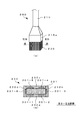
図3は、本実施形態に係る描画システムに適用される電子絵筆の一構成例を示す要部構成図である。図3(a)は、本実施形態に係る電子絵筆の筆先部分を示す概略斜視図であり、図3(b)は、図3(a)に示したIIIB−IIIB線(本明細書では、図中に示したローマ数字の「3」に対応する符号として便宜的に「III」を用いる)に沿った穂先の断面を示す図である。図4は、本実施形態に係る描画システムに適用される電子絵筆を示す要部分解図である。図4(a)は、本実施形態に係る電子絵筆に適用される穂先の構造を説明するための分解斜視図であり、図4(b)は、図4(a)に示したIVB−IVB線(本明細書では、図中に示したローマ数字の「4」に対応する符号として便宜的に「IV」を用いる)から見た矢視図である。
(Electronic paint brush)
FIG. 3 is a main part configuration diagram showing a configuration example of an electronic paintbrush applied to the drawing system according to the present embodiment. FIG. 3A is a schematic perspective view showing a brush tip portion of the electronic paintbrush according to the present embodiment, and FIG. 3B is a IIIB-IIIB line (in this specification, shown in FIG. 3A). It is a figure which shows the cross section of the tip along the point which uses "III" as a code | symbol corresponding to the Roman numeral "3" shown in the figure for convenience. FIG. 4 is an essential part exploded view showing an electronic paintbrush applied to the drawing system according to the present embodiment. FIG. 4A is an exploded perspective view for explaining the structure of a tip applied to the electronic paintbrush according to the present embodiment, and FIG. 4B is an IVB-IVB shown in FIG. It is an arrow view seen from a line (in this specification, "IV" is used for convenience as a symbol corresponding to the Roman numeral "4" shown in the figure).
本実施形態に係る電子絵筆200は、例えば図3(a)に示すように、概略、軸に沿って延在した形状を有する棒状の柄軸210と、柄軸210の一端側の端部である固定用基部210aに取り付けられた穂先230と、を有している。ここで、本実施形態においては、電子絵筆200は、一般の絵画の制作に用いられる平筆と同等の外観および構成を有している。
An
穂先230は、図3(a)および図4(a)に示すように、柄軸210の延在方向と同方向(図面上下方向)に複数の筆毛が配向されて束ねられている。穂先230の一端側は、固定用基部210aに挿入されて柄軸210に固定された固定端を構成し、他端側は、タッチパネル102に接触することにより所望の撓りを生じるように自由端(または可動端)を構成している。ここで、穂先230を構成する各筆毛は、一般的な絵筆等に使用される動物の体毛や樹脂繊維等を適用することができ、筆毛を束ねた穂先230の状態で、適度な可撓性を有するように、筆毛の材質や寸法(細さや長さ等)、本数、束ね方等が設定されている。
As shown in FIGS. 3 (a) and 4 (a), the
本実施形態に係る平筆型の電子絵筆200においては、図3(a)、(b)に示すように、穂先230の断面が略長方形または略矩形を有している。また、穂先230中には、図3(b)および図4(a)、(b)に示すように、6個の圧電センサー201−1〜201−6(全ての圧電センサー201−1〜201−6を指す場合には「圧電センサー201」と表記する)が柄軸210または筆毛と同方向に配向され、かつ、各圧電センサー201−1〜201−6が所定の位置関係および相対角度を有した状態で束ねられている。
In the flat brush type
具体的には、穂先230は、例えば図3(b)および図4(a)、(b)に示すように、断面形状が長方形状になるように筆毛が角柱状に束ねられ、その長辺と短辺(または、隣接する2辺)が略直角をなす中心毛束231と、断面形状が長方形状になるように筆毛が角柱状に束ねられ、中心毛束231の各辺に沿って配置される外周毛束232a〜232dと、を有している。そして、これらの中心毛束231と各外周毛束232a〜232dとの境界には、圧電センサー201−1〜201−6が挟持されるように配置されている。すなわち、図3(b)および図4(b)に示すように、長方形状の断面を有する中心毛束231において、対向する一対の長辺(図面下辺および上辺)の各々に沿って、各2箇所に圧電センサー201−1、201−2および201−4、201−5が配置され、また、対向する一対の短辺(図面右辺および左辺)の各々に沿って、各1箇所に圧電センサー201−3および201−6が配置されている。ここで、各圧電センサー201−1〜201−6は、後述するように、短冊状の平面を有するフィルム部材からなり、それぞれの平面が上記の境界面に沿って延在するように配置されている。これにより、圧電センサー201−1、201−2および201−4、201−5と、圧電センサー201−3および201−6とは、それぞれの平面が相対的に直交する方向を向くように配置される。そして、図4(a)、(b)に示すように、各長辺側に配置された各2個の圧電センサー201−1、201−2および201−4、201−5は、それぞれ外周毛束232aおよび232cにより被覆された状態で中心毛束231に束ねられ、また、各短辺側に配置された各1個の圧電センサー201−3および201−6は、それぞれ外周毛束232bおよび232dにより被覆された状態で中心毛束231に束ねられている。これにより、図3(b)および図4(a)に示すように、断面が長方形または矩形を有する穂先230が形成される。
Specifically, for example, as shown in FIG. 3B and FIGS. 4A and 4B, the
なお、本実施形態においては、穂先230中に6個の圧電センサー201−1〜201−6が配置され、かつ、圧電センサー201−1、201−2および201−4、201−5と、圧電センサー201−3および201−6とが、相対的に直交する方向を向くように配置された構成について説明したが、本発明はこれに限定されるものではない。すなわち、上述した描画システムに適用される電子絵筆は、少なくとも穂先230中に複数の圧電センサーが配置され、それらの圧電センサーのうちの、任意の一対の圧電センサーの平面が相対的に異なる2方向を向くように配置されているものであれば、圧電センサーの個数や配置を任意に設定することができる。ここで、本発明に適用される描画制御方法においては、後述するように、複数の圧電センサーの平面を相対的に異なる2方向に向けて配置することにより、穂先230の撓り状態に応じて入力操作時の電子絵筆200の運筆状態をベクトル合成処理により判別する手法を用いている。したがって、CPU106におけるベクトル合成処理の処理負担を軽減するためには、複数の圧電センサーの平面が相対的に直交する方向を向くように配置された構成を適用することがより好ましい。しかしながら、後述する手法によれば、複数の圧電センサーの複数の平面が互いに交差する向きに配置されていれば、電子絵筆200の運筆状態を検出することができる。
In the present embodiment, six piezoelectric sensors 201-1 to 201-6 are disposed in the
次いで、上述したような電子絵筆200の機能構成について説明する。
図5は、本実施形態に係る描画システムに適用される電子絵筆の一構成例を示す機能ブロック図である。
Next, the functional configuration of the
FIG. 5 is a functional block diagram showing a configuration example of an electronic paintbrush applied to the drawing system according to the present embodiment.
電子絵筆200は、図5に示すように、概略、圧電センサー201と、差動増幅部202と、フィルタ/ADC203と、地磁気センサー204と、記憶部205と、通信機能部206と、CPU207と、電源供給部208と、電源スイッチ209と、ブリッジ回路241と、駆動電源部242と、駆動制御スイッチ243と、を有している。
As shown in FIG. 5, the
圧電センサー201(201−1〜201−6)は、上述したように、穂先230中に複数個配置され、電子絵筆200の穂先230をタブレット端末100に接触させる入力操作において、当該穂先230の撓りに応じて同様に撓ることにより、圧電効果により発生する電圧が取り出されて、後述するブリッジ回路241に出力される。また、圧電センサー201は、後述するブリッジ回路241を介して印加される電圧に基づいて、逆圧電効果により穂先230に所望の曲げ応力が付与される。圧電センサー201(201−1〜201−6)は、適度な可撓性を有するように、材料や厚さ等が設定されていて、例えば、薄い平板状に形成されている。
As described above, a plurality of piezoelectric sensors 201 (201-1 to 201-6) are arranged in the
差動増幅部202は、後述するブリッジ回路241から出力される2つの電圧の差分を増幅することにより、穂先230の撓りに応じた、所定の電圧レベルを有するセンサー電圧(検出電圧)を生成して出力する。また、フィルタ/ADC203は、ハイパスフィルタおよびローパスフィルタからなるフィルタ回路と、アナログ−デジタル変換回路(ADC)とを有している。フィルタ回路は、上記差動増幅部202から出力される圧電センサー201の検出電圧からノイズ成分を除去し、ADCは、ノイズ除去された検出電圧をアナログ信号からデジタル信号に変換する。デジタル信号に変換された検出電圧は、CPU207に取り込まれる。
The
なお、本実施形態においては、フィルタ/ADC203に設けられたハードウェアとしてのフィルタ回路やADCを用いて、ノイズ成分の除去処理およびアナログ−デジタル変換処理を行う場合について説明したが、この構成に限定されるものではない。すなわち、CPU207に内蔵されたソフトウェアとしてのデジタルフィルタ機能やADC機能を使用して、ノイズ除去処理やアナログ−デジタル変換処理を行うものであってもよい。これによれば、電子絵筆200に内蔵されるハードウェア構成を削減することができ、電子絵筆200の小型化やコストの削減を図ることができる。
In the present embodiment, the case of performing noise component removal processing and analog-digital conversion processing using a filter circuit or ADC as hardware provided in the filter /
地磁気センサー204は、上述したタブレット端末100と同様に、地球の磁場の向きを計測することにより、電子絵筆200の回転方向や傾斜方向に関する情報(絵筆姿勢情報)を取得する。この絵筆姿勢情報は、後述する通信機能部206を介して、上述したタブレット端末100に送信されて、端末姿勢情報とともに、タブレット端末100に対する電子絵筆200の相対的な回転角度や傾斜角度を算出する際に用いられる。
Similar to the
記憶部205は、圧電センサー201により取得された検出電圧や、地磁気センサー204により取得された絵筆姿勢情報、電子絵筆200の穂先230の形状(平筆型)に関する筆種別情報、運筆時の操作感を任意の状態に近似させるための操作感制御情報等を一時保存するランダムアクセスメモリ(RAM)を有する。また、記憶部205は、圧電センサー201や差動増幅部202、フィルタ/ADC203、地磁気センサー204、記憶部205、通信機能部206、ブリッジ回路241、駆動電源部242、駆動制御スイッチ243における各種機能を実行するための制御プログラムや、後述する本実施形態に係る描画制御動作を実行するための制御プログラムを格納する読み出し専用メモリ(ROM)を含むものであってもよい。CPU207は、これらの制御プログラムに従って処理を実行することにより、電子絵筆200の絵筆姿勢情報を常時把握するとともに、タブレット端末100への入力操作時における電子絵筆200の運筆状態に関する情報を収集して、タブレット端末100に所定のタイミング(随時、あるいは、任意のタイミング)で送信する制御を行う。加えて、CPU207は、タブレット端末100から送信された操作感制御情報に基づいて、タブレット端末100への入力操作時に、駆動電源部242および駆動制御スイッチ243を制御して圧電センサー201に所定の曲げ応力を発生させて、穂先230の撓り状態を制御する。なお、これらの制御プログラムは、CPU207に予め組み込まれているものであってもよい。
The
通信機能部206は、少なくとも上述した電子絵筆200の穂先230に混在するように配置された圧電センサー201により得られた検出電圧や、地磁気センサー204により得られた検出信号を、上述したタブレット端末100に送信する。圧電センサー201により得られた検出電圧は、上述したタブレット端末100において、電子絵筆200の運筆状態を判別するための各種データ(穂先230の撓り量やその撓り方向、その先端荷重)を算出するために使用される。また、地磁気センサー204により得られた検出信号は、タブレット端末100に対する電子絵筆200の絵筆姿勢情報(相対的な位置関係や傾斜状態等)を把握するために使用される。また、通信機能部105は、上述したタブレット端末100から送信される、運筆時の穂先の撓り状態を制御する操作感制御情報を受信する。また、通信機能部206は、タブレット端末100に対して、上記の各種データの送信に必要な通信制御に関連する情報を送受信する。
The
電源供給部208は、電子絵筆200を用いた入力操作において支障とならないように、軽量大容量のリチウムイオン電池等の二次電池や、市販のボタン電池等の一次電池等からなる動作電源を備えている。そして、電源スイッチ209をオンまたはオフ操作することにより、圧電センサー201や差動増幅部202、フィルタ/ADC203、地磁気センサー204、記憶部205、通信機能部206、CPU207等の各構成に対して、電源供給部208から電源電圧が供給、または、その供給が遮断される。なお、タブレット端末100との間で各種データ等を送受信する手法として、電子絵筆200とタブレット端末100が通信ケーブル(例えばUSBケーブル等)を介して接続されている場合には、動作電源として、タブレット端末100の電源供給部107から電力が供給されるものであってもよい。また、この場合には、動作電源として、商用電源を適用することもできる。
The
次に、本実施形態に係る電子絵筆に適用されるブリッジ回路について具体的に説明する。
図6は、本実施形態に係る電子絵筆に適用されるブリッジ回路の構成例を示す回路図である。図6(a)は、圧電センサーを含むブリッジ回路の第1の構成例を示す等価回路であり、図6(b)は、同ブリッジ回路の第2の構成例を示す等価回路である。ここで、図6(a)、(b)において、同等の構成については同一の符号を付して示す。
Next, the bridge circuit applied to the electronic paintbrush according to the present embodiment will be specifically described.
FIG. 6 is a circuit diagram illustrating a configuration example of a bridge circuit applied to the electronic paintbrush according to the present embodiment. FIG. 6A is an equivalent circuit showing a first configuration example of a bridge circuit including a piezoelectric sensor, and FIG. 6B is an equivalent circuit showing a second configuration example of the bridge circuit. Here, in FIG. 6 (a), (b), about the same structure, the same code | symbol is attached | subjected and shown.
本実施形態に適用されるブリッジ回路の第1の構成例は、いわゆるCCブリッジ回路を有し、例えば図6(a)に示すように、可変コンデンサC1とコンデンサC2とからなる直列回路と、コンデンサCpとコンデンサC2とからなる直列回路とが、駆動電圧Vcが印加される接点Paと接地電位に接続された接点Pbとの間に並列に接続されている。ここで、可変コンデンサC1とコンデンサC2とは接点Pcを介して接続され、コンデンサCpとコンデンサC2とは接点Pdを介して接続されている。また、図中、Vpは圧電センサーの歪みによって発生する電圧であり、コンデンサCpは圧電センサーのキャパシタンスである。すなわち、圧電センサーの発生電圧VpおよびコンデンサCpは圧電センサーの等価回路を構成する。また、駆動電圧Vcは、駆動電源部242から駆動制御スイッチ243を介して所定のタイミングで供給される。
The first configuration example of the bridge circuit applied to the present embodiment has a so-called CC bridge circuit. For example, as shown in FIG. 6A, a series circuit including a variable capacitor C1 and a capacitor C2, and a capacitor A series circuit composed of Cp and a capacitor C2 is connected in parallel between a contact point Pa to which the drive voltage Vc is applied and a contact point Pb connected to the ground potential. Here, the variable capacitor C1 and the capacitor C2 are connected via a contact Pc, and the capacitor Cp and the capacitor C2 are connected via a contact Pd. In the figure, Vp is a voltage generated by distortion of the piezoelectric sensor, and a capacitor Cp is the capacitance of the piezoelectric sensor. That is, the voltage Vp generated by the piezoelectric sensor and the capacitor Cp constitute an equivalent circuit of the piezoelectric sensor. The drive voltage Vc is supplied from the drive
このような回路構成を有するブリッジ回路において、接点PdおよびPcの電圧V1、V2は、コンデンサCp、C1、C2、発生電圧Vp、駆動電圧Vcを用いて、それぞれ次式(11)、(12)で表すことができる。 In the bridge circuit having such a circuit configuration, the voltages V1 and V2 of the contacts Pd and Pc are expressed by the following equations (11) and (12) using capacitors Cp, C1 and C2, a generated voltage Vp, and a drive voltage Vc, respectively. Can be expressed as

ここで、センサー電圧Vsを、Vs:=V1−V2と定義し、可変コンデンサC1の容量が圧電センサーのコンデンサCpの容量と等しくなるように回路のバランスを設定する(C1=Cp)と、センサー電圧Vsは、次式(13)のように表すことができる。ここで、K2は、次式(14)のように表される。なお、上記のように定義されたセンサー電圧Vsは、上述した差動増幅部202において上記の電圧V1、V2の差分を演算し、所定の電圧レベルに増幅することにより得られる。
Here, the sensor voltage Vs is defined as Vs: = V1-V2, and the balance of the circuit is set so that the capacitance of the variable capacitor C1 is equal to the capacitance of the capacitor Cp of the piezoelectric sensor (C1 = Cp). The voltage Vs can be expressed as the following formula (13). Here, K2 is expressed as the following equation (14). The sensor voltage Vs defined as described above is obtained by calculating the difference between the voltages V1 and V2 in the
また、本実施形態に適用されるブリッジ回路の第2の構成例は、いわゆるRCブリッジ回路を有し、例えば図6(b)に示すように、抵抗R1と抵抗R2とからなる直列回路と、コンデンサCpとコンデンサC2とからなる直列回路とが、駆動電圧Vcが印加される接点Paと接地電位に接続された接点Pbとの間に並列に接続されている。ここで、抵抗R1と抵抗R2とは接点Pcを介して接続され、コンデンサCpとコンデンサC2とは接点Pdを介して接続されている。すなわち、本構成例に係るブリッジ回路は、上述した第1の構成例に係るブリッジ回路(図6(a))において、可変コンデンサC1とコンデンサC2とからなる直列回路を、抵抗R1と抵抗R2とからなる直列回路に置き換えた回路構成を有している。 Further, the second configuration example of the bridge circuit applied to the present embodiment includes a so-called RC bridge circuit, for example, as illustrated in FIG. 6B, a series circuit including a resistor R1 and a resistor R2, A series circuit composed of a capacitor Cp and a capacitor C2 is connected in parallel between a contact Pa to which the drive voltage Vc is applied and a contact Pb connected to the ground potential. Here, the resistor R1 and the resistor R2 are connected via a contact Pc, and the capacitor Cp and the capacitor C2 are connected via a contact Pd. That is, the bridge circuit according to this configuration example includes a series circuit including the variable capacitor C1 and the capacitor C2 in the bridge circuit according to the first configuration example described above (FIG. 6A). The circuit configuration is replaced by a series circuit consisting of
このような回路構成を有するブリッジ回路において、接点PdおよびPcの電圧V1、V2は、コンデンサCp、C2、抵抗R1、R2、発生電圧Vp、駆動電圧Vcを用いて、それぞれ次式(21)、(22)で表すことができる。 In the bridge circuit having such a circuit configuration, the voltages V1 and V2 of the contacts Pd and Pc are expressed by the following equations (21), respectively using capacitors Cp and C2, resistors R1 and R2, a generated voltage Vp, and a drive voltage Vc. (22).
ここで、上述した第1の構成例と同様に、センサー電圧Vsを、Vs:=V1−V2と定義し、コンデンサCpとコンデンサC2の比が抵抗R1と抵抗R2の比と等しくなるように素子定数を設定する(C2/Cp=R2/R1)と、センサー電圧Vsは、次式(23)のように表すことができる。ここで、K2は、次式(24)のように表される。 Here, similarly to the above-described first configuration example, the sensor voltage Vs is defined as Vs: = V1−V2, and the ratio of the capacitor Cp and the capacitor C2 is equal to the ratio of the resistor R1 and the resistor R2. When a constant is set (C2 / Cp = R2 / R1), the sensor voltage Vs can be expressed as the following equation (23). Here, K2 is expressed as the following equation (24).
上述した第1および第2の構成例に係るブリッジ回路241においては、上記の(13)、(14)式、または、(23)、(24)式から明らかなように、センサー電圧Vsは駆動電圧Vcの影響が取り除かれ、圧電センサー201の歪みに比例する信号(発生電圧Vp)に、定数(ゲインK2)が乗算された分圧の形で取り出すことができる。すなわち、本構成例に係るブリッジ回路241によれば、圧電センサーの圧電効果を利用して、圧電センサー201の撓りに応じて発生する電圧Vp(すなわち、発生電圧Vpに依存するセンサー電圧Vs)を検出することにより、圧電センサー201の撓り状態を取得することができるセンシング機能が実現される。また、本構成例に係るブリッジ回路241によれば、圧電センサーの逆圧電効果を利用して、駆動電圧Vcに基づく印加電圧Va(=Vc−V1)を圧電センサー201に印加することにより、この印加電圧Vaに応じた曲げ応力を圧電センサー201に付与することができるアクチュエータ機能が実現される。そして、これらのセンシング機能とアクチュエータ機能は、上述したブリッジ回路241に接続された同一の圧電センサー201において、同時並行的に実現される。すなわち、圧電センサー201−1〜201−6の各々を、検出器として機能させるとともに、アクチュエータとしても機能させることができる(セルフセンシング・アクチュエータ機能)。
In the bridge circuit 241 according to the first and second configuration examples described above, the sensor voltage Vs is driven as is apparent from the above equations (13), (14), or (23), (24). The influence of the voltage Vc is removed, and a signal (generated voltage Vp) proportional to the distortion of the
図5に示した駆動電源部242は、上述した電源供給部208と同等の、または、当該電源供給部208と同一の電源を備えている。ここで、駆動電源部242から供給される駆動電圧Vcは、CPU207から出力される電圧値制御信号に基づいて、その電圧値が任意に設定される。そして、CPU207から出力されるタイミング制御信号に基づいて、駆動制御スイッチ243を任意のタイミングでオンまたはオフ動作させることにより、上述したブリッジ回路241に対して、電圧値が設定された駆動電圧Vcが供給、または、その供給が遮断される。
The drive
次に、上述した構成を有する描画システムにおける入力操作解析方法および描画制御方法について説明する。
<入力操作解析方法>
まず、本実施形態に係る電子絵筆を適用した入力操作解析方法について説明する。
Next, an input operation analysis method and a drawing control method in the drawing system having the above-described configuration will be described.
<Input operation analysis method>
First, an input operation analysis method using the electronic paintbrush according to the present embodiment will be described.
図7は、本実施形態に係る描画システムに適用される電子絵筆を用いた入力操作の一例を示す概念図である。図7(a)は、電子絵筆の穂先の先端部分を平面視した場合の概略図であり、図7(b)は、入力操作時の穂先の撓り状態を示す概略斜視図である。ここで、図7(b)においては、図示を簡明にするために、穂先を構成する筆毛を省略し、圧電センサーの撓り状態のみを示した。図8は、本実施形態に適用される電子絵筆を特定方向に移動させた場合の穂先の撓り状態を解析するための説明図である。ここで、図8においては、図示を簡明にするために、穂先を構成する外周毛束を省略し、圧電センサーの撓り状態も示した。 FIG. 7 is a conceptual diagram illustrating an example of an input operation using an electronic paint brush applied to the drawing system according to the present embodiment. FIG. 7A is a schematic view when the tip of the tip of the electronic paintbrush is viewed in plan, and FIG. 7B is a schematic perspective view showing a bent state of the tip during an input operation. Here, in FIG.7 (b), in order to simplify illustration, the brush which comprises a tip was abbreviate | omitted and only the bending state of the piezoelectric sensor was shown. FIG. 8 is an explanatory diagram for analyzing the bending state of the tip when the electronic paintbrush applied to the present embodiment is moved in a specific direction. Here, in FIG. 8, in order to simplify the illustration, the outer peripheral hair bundle constituting the tip is omitted, and the bending state of the piezoelectric sensor is also shown.
上述したように、本実施形態に適用される電子絵筆200は、穂先230の中に、複数個の柔軟な構造の圧電センサー201−1〜201−6が配置されている。そして、図7(a)、(b)に示すように、電子絵筆200の穂先230をタブレット端末100のタッチパネル102の表面(入力面)に接触させて移動させる入力操作時に、電子絵筆200の筆使いや筆運びに応じた穂先230の撓り状態に追従して、各圧電センサー201−1〜201−6も変形するように構成されている。
As described above, in the
なお、以下の説明においては、図7(a)に示すように、タッチパネル102を視野側から平面視してx−y座標を規定した場合に、電子絵筆200の穂先230の先端部分を、例えば図中矢印の運筆方向に移動させた場合について説明する。具体的には、タッチパネル102の長辺をx軸、短辺をy軸とする。ここでは、説明を簡明にするために、便宜的に、電子絵筆200の穂先230の断面形状である長方形状の長辺をy軸方向に平行に設定し、短辺をx軸方向に平行に設定し、かつ、電子絵筆200の柄軸210をタッチパネル102の表面に対して垂直になるように保持した状態で、穂先230をタッチパネル102にやや押し付け気味にして、図7(a)、(b)中の矢印方向に平行移動させた場合を例にして説明する。なお、実際の入力操作においては、タッチパネル102に対する電子絵筆200の傾斜角度や穂先230の回転角度、穂先230の押し付け具合等、複数のパラメータを考慮して入力操作の解析が行われる。
In the following description, as shown in FIG. 7A, when the
上述した電子絵筆200の穂先230をタッチパネル102に接触させた初期状態においては、穂先230の先端部分(すなわち、タッチパネル102との接触領域)の形状は、図7(a)に示すように、穂先230の断面形状と略同一の長方形状(または矩形形状)を有している。この初期状態から、電子絵筆200を図7(a)、(b)中の矢印方向に移動させた(運筆した)場合の、穂先230の先端部分の変位について解析する。ここで、本実施形態においては、穂先230の先端部分の形状が長方形状(矩形形状)を有しているので、その四隅の頂点について変位方向と変位量が判明すれば、穂先230の先端部分全体の変位を推定することができる。
In the initial state in which the
すなわち、本実施形態においては、電子絵筆200の穂先230の内部に、短冊状の平面が相対的に直交するように短冊状の平面が配置された各圧電センサー201−1〜201−6の出力電圧を個別に検出することにより、x方向およびy方向の穂先230の撓り方向と撓り量が独立して検出される。そして、これらの変位成分をベクトル合成することにより、穂先230の先端部分の形状を規定する四隅の頂点の変位方向と変位量を推定して、穂先230の先端部分全体の変位状態、すなわち電子絵筆200の運筆状態を判別する。
In other words, in the present embodiment, the outputs of the piezoelectric sensors 201-1 to 201-6 in which the strip-shaped planes are arranged in the
具体的には、例えば図7(a)に示した運筆方向に電子絵筆200を移動させた場合、図8(a)〜(d)に示すように、圧電センサー201−1、201−2、201−4、201−5は、それぞれ−x方向に所定の撓りを生じ、また、圧電センサー201−3、201−6は、それぞれ+y方向に所定の撓りを生じる。これらの圧電センサー201−1〜201−6の撓りは、穂先230全体の撓り状態に対応している。
Specifically, for example, when the
これにより、図8(a)に示すように、穂先230の先端部分の長方形状(矩形形状)について、図中左上の頂点ULの変位方向と変位量は、当該頂点ULを構成する図面上側の短辺に対して平行になるように平面が配置された圧電センサー201−6と、当該頂点ULを構成する図面左側の長辺に対して平行になるように平面が配置された圧電センサー201−1とにおいて独立して検出された穂先230の撓り方向と撓り量からなる変位成分(ベクトルV6、V1)を、ベクトル合成することによりベクトルV16として表すことができる。すなわち、穂先230の先端部分の頂点ULの筆毛はベクトルV16のように撓っているものと推定することができる。
As a result, as shown in FIG. 8A, the displacement direction and displacement amount of the vertex UL at the upper left in the figure for the rectangular shape (rectangular shape) of the tip portion of the
他の頂点についても同様に、図8(b)に示すように、図中左下の頂点LLの変位方向と変位量は、当該頂点LLを構成する短辺に対して平行になるように配置された圧電センサー201−3と、同長辺に対して平行になるように配置された圧電センサー201−2とにおいて独立して検出された穂先230の撓り方向と撓り量からなる変位成分(ベクトルV3、V2)を、ベクトル合成することによりベクトルV23として表すことができる。また、図8(c)に示すように、図中右上の頂点URの変位方向と変位量は、当該頂点URを構成する短辺に対して平行になるように配置された圧電センサー201−6と、同長辺に対して平行になるように配置された圧電センサー201−5とにおいて独立して検出された穂先230の撓り方向と撓り量からなる変位成分(ベクトルV6、V5)を、ベクトル合成することによりベクトルV56として表すことができる。また、図8(d)に示すように、図中右下の頂点LRの変位方向と変位量は、当該頂点LRを構成する短辺に対して平行になるように配置された圧電センサー201−3と、同長辺に対して平行になるように配置された圧電センサー201−4とにおいて独立して検出された穂先230の撓り方向と撓り量からなる変位成分(ベクトルV3、V4)を、ベクトル合成することによりベクトルV34として表すことができる。すなわち、穂先230の先端部分の各頂点LL、UR、LRの筆毛は、各々ベクトルV23、V56、V34のように撓っているものと推定することができる。
Similarly, for the other vertices, as shown in FIG. 8B, the displacement direction and the displacement amount of the lower left vertex LL in the figure are arranged so as to be parallel to the short side constituting the vertex LL. Displacement component consisting of the bending direction and the amount of bending of the
よって、これらのベクトルV16、V23、V34、V56を用いることにより、穂先230の先端部分の長方形状の四隅の変位が推定される。また、この長方形状の四隅や圧電センサー201−1〜201−6の配置位置以外の位置(例えば長方形状の内部)における穂先230の撓り方向と撓り量は、上述した圧電センサー201−1〜201−6の配置位置における撓り方向と撓り量を、当該圧電センサー201−1〜201−6間で線形補間を行うことにより推定することができる。
Therefore, by using these vectors V16, V23, V34, and V56, the displacement of the four corners of the rectangular shape of the tip portion of the
次に、本実施形態に係る電子絵筆に適用される圧電センサーについて説明する。
図9は、本実施形態に適用される圧電センサーの一構成例を示す概略図である。図9(a)は、圧電センサーの概略構造を示す断面図であり、図9(b)は、その斜視図であり、図9(c)は、圧電センサーの撓り方向と発生電荷の極性との関係を示す概略図である。なお、図9(c)においては、図示の都合上、ハッチングの一部を省略して示す。図10は、圧電センサーの検出原理(撓り量と先端荷重との関係)を説明するための図である。
Next, a piezoelectric sensor applied to the electronic paintbrush according to the present embodiment will be described.
FIG. 9 is a schematic diagram illustrating a configuration example of a piezoelectric sensor applied to the present embodiment. FIG. 9A is a cross-sectional view showing a schematic structure of the piezoelectric sensor, FIG. 9B is a perspective view thereof, and FIG. 9C is a bending direction of the piezoelectric sensor and the polarity of generated charges. It is the schematic which shows the relationship. In FIG. 9C, a part of hatching is omitted for convenience of illustration. FIG. 10 is a diagram for explaining the detection principle of the piezoelectric sensor (the relationship between the amount of bending and the tip load).
本実施形態に適用される圧電センサー201(201−1〜201−6)は、例えば図9(a)、(b)に示すように、所定の方向(図面左右方向)に延在する短冊状の圧電フィルム21の両面(図面上面および下面)に薄膜電極22aおよび22bが形成された圧電体20と、当該圧電体20が一面側(図面上面側)に形成された絶縁性の弾性基材23と、を有している。圧電フィルム21は、例えばポリフッ化ビニリデン(PVDF)等の高分子樹脂材料を適用することができる。ポリフッ化ビニリデンは、延伸加工することにより圧電性が発現するので、高分子圧電フィルムとして適用することができる。このような圧電フィルム21は厚み方向に分極する特性を有しているので、圧電フィルム21の両面に金属膜からなる薄膜電極22aおよび22bを蒸着形成することにより圧電体20を形成し、さらに、この圧電体20を弾性基材23に接合することにより積層構造を有する圧電センサー201が形成される。この弾性基材23は、設計上のその必要がなければ、用いなくてもよい。そして、図9(a)、(b)に示すように、圧電センサー201の延在方向(短冊の長手方向)の一端側(図面左方側)を、上述した固定用基部210aを介して柄軸210に固定することにより、本実施形態と等価の構造を有する、柔軟な片持ち梁構造の圧電センサー201が形成される。このような圧電センサー201において、薄膜電極22b側を接地し、薄膜電極22a側を電圧検出器(上述したブリッジ回路241、差動増幅部202およびフィルタ/ADC203に相当する)に接続することにより、圧電センサー201の撓り量に応じて圧電フィルム21において発生した電荷を電圧成分(上述した発生電圧Vpに対応する)として検出することができる。また、このような構造を有する圧電センサー201においては、図9(c)に示すように、圧電センサー201の延在方向の他端側(図面右方側)が図面上方に変位するか、図面下方に変位するかによって、薄膜電極22aおよび22bに発生する電荷の極性が異なるという特性を有しているので、薄膜電極22aに接続された電圧検出器により検出された、電荷または出力電圧(上述した発生電圧Vp)の極性に基づいて、圧電センサー201の撓り方向を判別することもできる。
The piezoelectric sensor 201 (201-1 to 201-6) applied to the present embodiment is a strip shape extending in a predetermined direction (left-right direction in the drawing) as shown in FIGS. 9A and 9B, for example. A
具体的には、圧電センサーの撓り量の検出原理は、一般に次のように説明される。
まず、圧電センサー201を含むブリッジ回路241において、圧電センサー201の撓りに応じて発生した電荷に基づく電圧値Vを測定する。これにより、上記電圧値Vとブリッジ回路241に搭載されたコンデンサ容量Cに基づいて、圧電センサー201で発生した電荷量Qは、次式(31)のように表すことができる。
Q=C・V ・・・(31)
Specifically, the principle of detecting the bending amount of the piezoelectric sensor is generally explained as follows.
First, in the bridge circuit 241 including the
Q = C · V (31)
一方、この発生電荷量Qは、圧電体内部の応力σに比例するので、次式(32)のように表すことができる。ここで、d31は圧電定数であり、Sは圧電体の面積である。
Q=d31・σ・S ・・・(32)
On the other hand, since this generated charge amount Q is proportional to the stress σ inside the piezoelectric body, it can be expressed as the following equation (32). Here, d31 is a piezoelectric constant, and S is the area of the piezoelectric body.
Q = d31 · σ · S (32)
また、本実施形態に適用される圧電センサー201は、上述したように、圧電フィルム
21と弾性基材23を積層して接着した「組合せ梁構造」と見なすことができるので、圧
電体内部に発生する応力σは、片持ち梁構造の圧電センサー201の先端に加重される力
に比例する。ここで、組合せ梁の理論により、圧電体内部に発生する応力σは、次式(3
3)のように表される。
Further, as described above, the
It is expressed as 3).
ここで、Eは圧電センサー201全体のヤング率(縦弾性係数)であり、yは圧電セン
サー201全体の中立軸(圧電センサー201が変形した場合であっても、固定端である
基部側からの長さが変化しない軸線)からの距離である。また、Ejは圧電センサー201各層のヤング率(縦弾性係数)であり、Ijは圧電センサー201各層の断面2次モーメントである。また、Mは図10(a)に示すように、長さLの片持ち梁構造の圧電センサー201の先端に力Fが加重された場合の曲げモーメントであって、次式(34)のように表される。
M=F・L ・・・(34)
Here, E is the Young's modulus (longitudinal elastic modulus) of the entire
M = F · L (34)
上記の(32)、(33)、(34)式により、圧電センサー201の先端に加重された力(先端荷重)Fは、次式(35)のように表される。
By the above equations (32), (33), and (34), the force (tip load) F applied to the tip of the
一方、組合せ梁の理論により、図10(b)に示すように、圧電センサー201の先端に力Fが加重された場合に生じる撓り量δは、次式(36)のように表される。
On the other hand, as shown in FIG. 10B, the bending amount δ generated when the force F is applied to the tip of the
このような検出原理を用いて、穂先230の撓りに伴って、圧電センサー201の薄膜電極22aおよび22b間に生じる電圧を検出することにより、圧電センサー201の他端側(図9、図10の右方側)の変位に基づく撓り量およびその撓り方向、並びに、先端荷重を算出(推定)することができる。
Using such a detection principle, by detecting the voltage generated between the thin film electrodes 22a and 22b of the
次いで、上記の原理により得られた圧電センサー201の撓り量δおよびその撓り方向、並びに、先端荷重Fに基づいて、電子絵筆200を任意の方向に移動(運筆)させた場合のフットプリント(ここでは、穂先230の先端部分をタッチパネルに接触させた際に、穂先230の先端部分の頂点UL、LL、UR、LRにより形成される矩形状の領域に対応する)の形状と、当該フットプリントの領域内における筆圧分布を推定する手法について説明する。
Next, a footprint when the
図11は、本実施形態に係る入力操作解析方法により推定される電子絵筆の運筆状態を説明するための図である。図11(a)〜(c)の各上図は、電子絵筆の運筆状態とフットプリントの形状を示す概略斜視図であり、同各下図は、上図に示したフットプリントを平面視した場合の概略図である。また、図11(d)は、図11(a)〜(c)に示した運筆状態におけるフットプリントの形状と筆圧分布の関係を示す概略図である。なお、ここでは、図7および図8において説明を簡明にするために電子絵筆200を平行移動させた場合の運筆状態とは異なり、電子絵筆200を任意の傾斜角度で、かつ、穂先230を任意の回転角度で押し付けながら移動させた場合を例にして説明する。この例においては、電子絵筆を用いた実際の入力操作時における運筆状態に近似するものとなる。
FIG. 11 is a diagram for explaining the stroke state of the electronic paintbrush estimated by the input operation analysis method according to the present embodiment. 11A to 11C are schematic perspective views showing the stroke state of the electronic paintbrush and the shape of the footprint, and the lower figures are a plan view of the footprint shown in the upper figure. FIG. FIG. 11D is a schematic diagram showing the relationship between the shape of the footprint and the writing pressure distribution in the handwriting state shown in FIGS. Here, in order to simplify the description in FIGS. 7 and 8, the
具体的には、図11(a)に示すように、タッチパネル102の表面に電子絵筆200の穂先230の先端部分を接触させ、次いで、例えば図11(b)に示すように、電子絵筆200を任意の回転角度および傾斜角度で、例えば図11(c)に示すように、任意の運筆方向に移動させた場合、上述した圧電センサー201により検出された撓り量δと撓り方向に基づいて、フットプリントの形状が推定される。すなわち、図11(a)に示した状態では、フットプリント10の形状は、電子絵筆200の穂先230がタブレット端末100に接触していない状態の、穂先230の先端部分の形状と略同一の長方形状を有している。そして、図11(b)に示した状態では、フットプリント11の形状を規定する四隅の頂点UL、LL、UR、LRのうち、頂点ULを除く3つの頂点LL、UR、LRが、図中矢印で示すように、それぞれ所定の位置に変位して、不等辺の矩形形状に変形する。そして、図11(c)に示した状態では、フットプリント11の形状を規定する四隅の頂点UL、LL、UR、LRのすべてがそれぞれ所定の位置に変位して、図11(b)に示した矩形形状を有するフットプリント11が、図中矢印で示すように、任意の方向(運筆方向)に平行移動される。ここで、フットプリント11の形状を規定する四隅の頂点UL、LL、UR、LRは、図8に示したように、電子絵筆200の穂先230の先端部分の形状を規定する四隅の頂点に対応する。したがって、当該穂先230中に配置された各圧電センサー201の撓り量δとその方向からなるベクトルを合成することにより、フットプリント10、11の形状を規定する四隅の頂点UL、LL、UR、LRの位置が推定されるので、これらの頂点間を結線することにより得られる矩形形状がフットプリント10、11の形状として規定される。
Specifically, as shown in FIG. 11 (a), the tip of the
また、電子絵筆200の穂先230がタブレット端末100に接触した際の圧力(接触圧)は、穂先230中に配置された各圧電センサー201により検出された先端荷重Fに基づいて算出される。すなわち、上述したようにして形状が設定されたフットプリント11において、当該形状を規定する四隅の頂点UL、LL、UR、LRにおける接触圧は、各圧電センサー201により検出された先端荷重Fを、図8に示した場合と同様にベクトル合成して、合成ベクトルの大きさに基づいて算出(推定)される。そして、各頂点UL、LL、UR、LRにおける接触圧の値に基づいて、上記の矩形形状を有するフットプリント11の領域内において、2次元的に線形補間を行うことにより、図11(d)に示すように、当該領域内における接触圧の分布(すなわち、筆圧分布)が得られる。なお、図11(d)は、図11(b)に示したように、電子絵筆200を任意の方向に、任意の角度で傾斜させた場合のフットプリント11の形状(上図)と、その場合の筆圧分布(下図)を示すものである。ここでは、便宜的に、電子絵筆200の傾斜により接触圧が高くなった頂点LR付近を濃色で示し、一方、電子絵筆200の傾斜によっても接触圧がほとんど変わらない、あるいは、接触圧が低くなった頂点UL付近を淡色で示した。すなわち、フットプリント11の領域内において、接触圧が高い頂点LR付近から接触圧が低い頂点UL付近に向かって接触圧の値が順次低くなるように傾斜分布している。
The pressure (contact pressure) when the
このように、本実施形態に係る描画システムにおいては、電子絵筆200の穂先230の内部に配置された圧電センサー201の圧電効果を用いて、穂先230の撓りに応じて圧電センサー201に発生する電圧を、ブリッジ回路241を介してセンサー電圧Vsとして検出し、圧電センサー201の撓り状態(撓り量や撓り方向)を解析することにより、電子絵筆200の運筆状態を判別することができる(センシング機能)。ここで、上記の一連の入力操作解析方法は、圧電センサーの圧電効果を利用するものであるが、この解析手法を圧電センサーの逆圧電効果に適用することにより、圧電センサー201を所望の撓り量および撓り方向に駆動させることができる。すなわち、図5に示した駆動電源部242から任意の電圧値に設定された駆動電圧Vcを、所定のタイミングでオン、オフ制御される駆動制御スイッチ243を介してブリッジ回路241に供給し、当該駆動電圧Vcに基づく所定の印加電圧を圧電センサー201の対向する薄膜電極22a、22b間に印加することにより、圧電センサー201を所望の撓り量および撓り方向に駆動させる曲げ応力を発生させる制御を行うことができる(アクチュエータ機能)。このようなアクチュエータ機能によれば、後述するように、電子絵筆200の運筆時における穂先230の撓り状態に応じて、当該撓り状態を元の状態に復元しようとするような所定の曲げ応力を発生させることにより、入力操作時の穂先230の変形に反発力が付与されるので、実際の絵筆におけるザラツキ感や粘り感等の操作感を再現することができる。
As described above, in the drawing system according to the present embodiment, the piezoelectric effect of the
なお、本実施形態においては、図4、図7に示したように、穂先230中に6個の圧電センサー201を配置した場合について説明したが、この圧電センサーの数を増やすことにより、フットプリントの形状や筆圧分布をより正確に把握することができ、後述する描画制御方法において、電子絵筆の筆使いや筆運びに応じた筆の特徴を描線や彩色等の表示により反映させることができる。
In the present embodiment, as shown in FIGS. 4 and 7, the case where six
<描画制御方法>
次に、本実施形態に係る描画システムにおいて、上述した入力操作解析方法を用いた描画制御方法について説明する。
図12は、本実施形態に係る描画システムにおける描画制御方法の一例を示すフローチャートである。
<Drawing control method>
Next, a drawing control method using the input operation analysis method described above in the drawing system according to the present embodiment will be described.
FIG. 12 is a flowchart illustrating an example of a drawing control method in the drawing system according to the present embodiment.
本実施形態に係る入力操作解析方法を用いた描画制御動作は、図12に示すように、概略、入力操作ステップ(S11)と、接触位置情報取得ステップ(S12)と、姿勢情報取得ステップ(S13)と、運筆情報取得ステップ(S14)と、運筆状態判別ステップ(S15)と、操作感付与ステップ(S16)と、画像処理ステップ(S17)と、表示情報制御ステップ(S18)と、を有している。 As shown in FIG. 12, the drawing control operation using the input operation analysis method according to the present embodiment is roughly summarized as an input operation step (S11), a contact position information acquisition step (S12), and an attitude information acquisition step (S13). ), A stroke information acquisition step (S14), a stroke state determination step (S15), an operational feeling imparting step (S16), an image processing step (S17), and a display information control step (S18). ing.
入力操作ステップ(S11)においては、まず、タブレット端末100の電源スイッチ108をオン操作して電源供給部107から各部に電源電圧を供給して、タブレット端末100における描画制御動作が可能な状態に設定する。また、電子絵筆200の電源スイッチ209をオン操作して電源供給部208から各部に電源電圧を供給して、電子絵筆200における描画制御動作が可能な状態に設定する。次いで、ユーザが使用する電子絵筆200の穂先形状を含む筆種別情報、および、電子絵筆200を用いた入力操作時の操作感に関する設定情報(操作感設定情報)がタブレット端末100に登録される。この筆種別情報および操作感設定情報の登録は、例えばユーザによりタブレット端末100の設定画面から直接入力設定される。なお、筆種別情報は、タブレット端末100および電子絵筆200における電源オン操作後に、電子絵筆200のCPU207が通信機能部206、105を介して当該情報を自動的に送信して、タブレット端末100のCPU106に通知して設定されるものであってもよい。ここで、筆種別情報は、少なくとも、上述した平筆型や丸筆型(詳しくは後述する)等の電子絵筆200の穂先230の種類や形状(長さや筆毛の太さ等)、穂先230中に配置される圧電センサー201の個数や配置等に関する情報を含んでいる。また、操作感設定情報は、電子絵筆200を用いた入力操作時に、ユーザーが希望する操作感、すなわち、実際の絵筆を用いて例えばキャンバス地に描画した際のザラツキ感や、油絵の具を使用した場合の粘り感等の種類やその強弱に関する情報を含んでいる。次いで、タブレット端末100のタッチパネル102に、ユーザが当該電子絵筆200を用いて、任意の位置に任意の強さで穂先230を接触させる入力操作を行う。
In the input operation step (S11), first, the
接触位置情報取得ステップ(S12)においては、タブレット端末100のCPU106が、タッチパネル102に接触している電子絵筆200の穂先230の位置を検出して、記憶部104の所定の記憶領域に接触位置情報として格納する。ここで、接触位置情報は、電子絵筆200の穂先230の接触領域の形状を規定する複数の基準点(すなわち、上述した矩形状の接触領域の場合には四隅の頂点UL、LL、UR、LRに相当する)を含むように検出される。これらの基準点は、同時に検出されるものであってもよいし、順次検出されるものであってもよい。なお、上記の接触位置情報は、タブレット端末100に適用されるタッチパネル102の位置検出方式(抵抗膜方式や静電容量方式等)に応じた手法で検出される。
In the contact position information acquisition step (S12), the
姿勢情報取得ステップ(S13)においては、タブレット端末100のCPU106が、地磁気センサー103によりタブレット端末100の回転方向や傾斜方向を検出して、記憶部104の所定の記憶領域に端末姿勢情報として格納する。また、電子絵筆200のCPU207が、地磁気センサー204により電子絵筆200の回転方向や傾斜方向を検出して、記憶部205の所定の記憶領域に絵筆姿勢情報として格納する。ここで、絵筆姿勢情報は、所定のタイミング(随時、あるいは、任意のタイミング)で通信機能部206を介してタブレット端末100に伝送されて、タブレット端末100において検出された接触位置情報および端末姿勢情報に関連付けて、記憶部104の所定の記憶領域に格納される。そして、CPU106により当該端末姿勢情報および絵筆姿勢情報に基づいて、当該接触位置におけるタブレット端末100に対する電子絵筆200の相対的な回転角度や傾斜角度が把握される。
In the posture information acquisition step (S 13), the
運筆情報取得ステップ(S14)においては、電子絵筆200のCPU207が、穂先230中に配置された複数の圧電センサー201の圧電効果を利用して、タブレット端末100のタッチパネル102に穂先230を接触させた際の、当該穂先230または圧電センサー201−1〜201−6の撓り状態(すなわち、撓り量および撓り方向)を検出して、記憶部205の所定の記憶領域に運筆情報として格納する。すなわち、電子絵筆200のCPU207が制御部として機能する。ここで、運筆情報は、所定のタイミング(随時、あるいは、任意のタイミング)で通信機能部206を介してタブレット端末100に伝送されて、タブレット端末100において検出された接触位置情報および端末姿勢情報に関連付けて、記憶部104の所定の記憶領域に格納される。そして、後述する運筆状態判別ステップにおいて、CPU106により当該運筆情報および接触位置情報、端末姿勢情報、絵筆姿勢情報に基づいて、電子絵筆200の運筆状態が把握される。
In the stroke information acquisition step (S14), the
なお、入力操作に伴って取得される、接触位置情報および姿勢情報、運筆情報は、上述したステップS12〜S14の順序に限定されるものではなく、これらのステップが任意の順番で実行されるものであってもよいし、これらのステップのうちの複数のステップが同時並行的に実行されるものであってもよい。なお、運筆状態を算出(推定)する際に、端末姿勢情報および絵筆姿勢情報を用いない場合には、姿勢情報取得ステップ(S13)を省略してよい。 Note that the contact position information, posture information, and stroke information acquired with the input operation are not limited to the order of steps S12 to S14 described above, and these steps are executed in an arbitrary order. Alternatively, a plurality of these steps may be executed in parallel. When calculating (estimating) the handwriting state, if the terminal posture information and the paintbrush posture information are not used, the posture information acquisition step (S13) may be omitted.
運筆状態判別ステップ(S15)においては、タブレット端末100のCPU106が、上述した入力操作解析方法を用いて、電子絵筆200において検出された運筆情報および絵筆姿勢情報、並びに、タブレット端末100において検出された接触位置情報および端末姿勢情報に基づいて、タブレット端末100に対する電子絵筆200による入力操作時における筆使いや筆運びに応じた筆の特徴に関する情報、すなわち、運筆状態(運筆方向やフットプリントの形状、筆圧分布)を判別する。なお、前述したように、運筆状態を算出(推定)する際に、端末姿勢情報および絵筆姿勢情報を用いなくてもよい。また、端末姿勢情報および絵筆姿勢情報を用いることによって、より多様なパラメータに基づいて運筆状態を算出(推定)することができる。
In the stroke state determination step (S15), the
操作感付与ステップ(S16)においては、まず、タブレット端末100のCPU106が、上記の運筆状態および操作感設定情報に基づいて、運筆時にユーザーが所望する操作感を実現するための操作感制御情報を生成して、記憶部104の所定の記憶領域に格納する。この操作感制御情報は、所定のタイミング(随時、あるいは、任意のタイミング)で通信機能部105を介して電子絵筆200に伝送されて、記憶部205の所定の記憶領域に格納される。そして、電子絵筆200のCPU207が、操作感制御情報に含まれる電圧値制御信号に基づいて駆動電源部242における駆動電圧Vcの電圧値を設定する。この駆動電圧Vcは、CPU207が、操作感制御情報に含まれるタイミング制御信号に基づいて駆動制御スイッチ243をオン、オフ制御することにより、所定のタイミングでブリッジ回路241に供給される。そして、ブリッジ回路241によりこの駆動電圧Vcに基づく所定の電圧Vaが圧電センサー201の薄膜電極22a、22bに印加されることにより、穂先230の内部に配置された複数の圧電センサー201の逆圧電効果を利用して、穂先230に所定の曲げ応力が付与される。
In the operation feeling imparting step (S16), first, the
具体的には、例えば、実際の絵筆を用いてキャンバス材に描画する際の操作感を実現する場合には、まず、上記の運筆状態に含まれる運筆速度や運筆方向に応じて、駆動制御スイッチ243のオン、オフ動作を小刻みに切り換え制御して、駆動電源部242からブリッジ回路241に所定の電圧値に設定された駆動電圧Vcを断続的に供給する。これにより、圧電センサー201に当該駆動電圧Vcに応じた所定の電圧Vaが断続的に印加されて、穂先230に所定の撓り量および撓り方向からなる曲げ応力(屈曲振動)が断続的に付与される。このように、穂先230に摩擦抵抗感を模擬するような動きが与えられるので、ユーザーは実際の絵筆を用いてキャンバス材に描画する際のザラツキ感に類似または近似する感触を体感することができる。すなわち、キャンバス材のザラツキ感が仮想現実化(再現)される。
Specifically, for example, when realizing an operation feeling when drawing on a canvas material using an actual paint brush, first, a drive control switch is selected according to the stroke speed and direction included in the stroke state. The drive voltage Vc set to a predetermined voltage value is intermittently supplied from the drive
また、例えば、実際の絵筆を用いて油絵の具で描画する際の操作感を実現する場合には、まず、上記の運筆状態に含まれる穂先230の撓り状態に応じて、当該撓り状態を元の状態に復元しようとするような曲げ応力が付与されるように駆動電源部242により駆動電圧Vcの電圧値を設定し、駆動制御スイッチ243を介してブリッジ回路241に供給する。これにより、圧電センサー201に当該駆動電圧Vcに応じた所定の電圧Vaが印加されて、穂先230に生じている撓り状態を元の状態に復元しようとするように所定の撓り量および撓り方向からなる曲げ応力が付与される。このように、穂先230の撓り変形に対して反発力が与えられるので、ユーザーは実際の絵筆を用いて油絵の具で描画する際の粘り感に類似または近似する感触を体感することができる。すなわち、油絵の具の粘り感が仮想現実化(再現)される。
Further, for example, when realizing an operation feeling when drawing with an oil paint using an actual paint brush, first, according to the bending state of the
画像処理ステップ(S17)においては、タブレット端末100のCPU106が、上記の運筆状態に基づいて、表示部101に電子絵筆200の入力操作に応じた描線や彩色等を画像として表示する際の、当該描線の位置や方向、太さ、彩色の種類や濃さ、擦れ具合等の各種のパラメータを設定する画像処理を行う。
In the image processing step (S17), when the
表示情報制御ステップ(S18)においては、タブレット端末100のCPU106が、上記の画像処理により設定されたパラメータに基づく描線や彩色等を表示部101に表示させる制御を行う。これにより、図1に示すように、タブレット端末100のタッチパネル102の表面に、ユーザが電子絵筆200を用いて任意の位置に任意の強さで穂先230を接触させると、表示部101の対応する位置に当該電子絵筆200の筆使いや筆運びに応じた筆の特徴を有する描線や彩色等が画像として表示される。
In the display information control step (S18), the
このように、本実施形態に係る描画システムにおいては、電子絵筆の穂先が、絵画の制作のために用いられる実際の絵筆と同様に、複数の筆毛が束ね合わされた構成を有している。これにより、描画対象であるタブレット端末等のタッチパネルに電子絵筆の穂先を接触させて入力操作を行った場合であっても、実際の絵筆の穂先と同等の挙動(撓り)が再現されるので、実際の絵筆と同等の操作性や操作感で直感的に入力操作を行うことができる電子描画システムを実現することができる。 Thus, in the drawing system according to the present embodiment, the tip of the electronic paintbrush has a configuration in which a plurality of brushes are bundled in the same manner as an actual paintbrush used for the production of a picture. As a result, even when an input operation is performed by bringing the tip of an electronic paint brush into contact with the touch panel of a tablet terminal or the like to be drawn, the behavior (bending) equivalent to the tip of an actual paint brush is reproduced. Thus, it is possible to realize an electronic drawing system capable of performing an input operation intuitively with the same operability and feeling as an actual paint brush.
また、本実施形態に係る描画システムにおいては、電子絵筆の穂先の内部に複数の柔軟な圧電センサーが配置され、これらの圧電センサーの圧電効果を利用して、穂先の撓り状態(撓り量や撓り方向)が正確に検出される。これにより、穂先の撓り状態に応じてフットプリントの形状や、その際の筆圧分布を正確に把握することができるので、入力操作時における電子絵筆の筆使いや筆運びに応じた筆の特徴(線の太さや擦れ具合、筆圧分布等)を描線や彩色等の表示に反映させることができる電子描画システムを実現することができる。 Further, in the drawing system according to the present embodiment, a plurality of flexible piezoelectric sensors are arranged inside the tip of the electronic paintbrush, and using the piezoelectric effect of these piezoelectric sensors, the bending state of the tip (the amount of bending) And the bending direction) are accurately detected. As a result, it is possible to accurately grasp the footprint shape and the pen pressure distribution at that time according to the bending state of the tip. It is possible to realize an electronic drawing system that can reflect features (line thickness, rubbing condition, writing pressure distribution, etc.) in the display of drawn lines and coloring.
加えて、本実施形態に係る描画システムにおいては、電子絵筆の穂先の内部に配置された圧電センサーに対して、所定の電圧を印加することにより、圧電センサーの逆圧電効果を利用して、穂先に所望の曲げ応力が発生するように制御することができる。これにより、ユーザーが所望する入力操作時の操作感(ザラツキ感や粘り感等)を仮想現実化することができるので、実際の絵筆を用いた絵画制作と同等の操作性や操作感で入力操作を行うことができる電子描画システムを実現することができる。 In addition, in the drawing system according to the present embodiment, by applying a predetermined voltage to the piezoelectric sensor disposed inside the tip of the electronic paintbrush, the tip is used by utilizing the reverse piezoelectric effect of the piezoelectric sensor. It is possible to control so as to generate a desired bending stress. This makes it possible to create a virtual reality of the user's desired input feeling (roughness, stickiness, etc.), so input operations can be performed with the same operability and feel as painting using an actual paint brush. An electronic drawing system capable of performing the above can be realized.
ここで、本実施形態に示したように、タブレット端末等の電子機器のタッチパネルの表面を入力面として入力操作を行う場合の、電子絵筆の操作感について検証する。一般に、タッチパネルの表面はガラス板や樹脂板等により構成され、均一な硬質面を有している。このような入力面においては、背景技術に示したような、硬質なペン先を有する周知の入力ペンを用いて入力操作を行った場合、その操作感が均一でしかなく、実際の絵筆を用いてキャンバス材に描画した際のような表面のザラツキ感や、油絵具の粘り感等の操作感を再現(仮想現実化)することができなかった。 Here, as shown in the present embodiment, the operational feeling of the electronic paintbrush when performing an input operation using the surface of the touch panel of an electronic device such as a tablet terminal as an input surface will be verified. In general, the surface of the touch panel is composed of a glass plate, a resin plate, or the like, and has a uniform hard surface. On such an input surface, when an input operation is performed using a known input pen having a hard pen tip as shown in the background art, the operation feeling is only uniform, and an actual paint brush is used. In other words, it was impossible to reproduce (virtual reality) the operational feeling such as the roughness of the surface as when drawing on canvas material and the stickiness of oil paint.
これに対して、本実施形態においては、電子絵筆の穂先が柔軟な筆毛を束ね合わせた実際の絵筆と同等の構成を有し、さらに、当該穂先の内部に配置された片持ち梁構造の圧電センサーに対して所定の電圧を印加することにより、圧電センサーの逆圧電効果を利用して、圧電センサーに所定の曲げ応力を発生させる制御が行われる。これにより、穂先に反発力や摩擦抵抗感等を模擬する力を発生させることができるので、電子絵筆の入力面がタッチパネルのように均一な硬質面であっても、実際の絵筆を用いた場合のキャンバス材表面のザラツキ感や油絵具の粘り感等の操作感を仮想現実化することができる。 On the other hand, in the present embodiment, the tip of the electronic paintbrush has a configuration equivalent to an actual paintbrush bundled with flexible brushes, and further has a cantilever structure disposed inside the tip. By applying a predetermined voltage to the piezoelectric sensor, control for generating a predetermined bending stress in the piezoelectric sensor is performed using the inverse piezoelectric effect of the piezoelectric sensor. As a result, force that simulates repulsive force, frictional resistance, etc. can be generated at the tip, so even if the input surface of the electronic paintbrush is a uniform hard surface like a touch panel, when using an actual paintbrush The feeling of operation such as the roughness of the surface of the canvas material and the stickiness of the oil paint can be realized in a virtual reality.
また、本実施形態に係る描画システムにおいては、穂先の内部に配置される各圧電センサーが穂先の撓り状態を検出するセンシング機能と、所定の曲げ応力を発生させるアクチュエータ機能との双方を有している。すなわち、同一の圧電センサーにより異なる2つの機能が実現されるので、電子絵筆に実装する回路や部品の数の増加を抑制して、簡易な回路構成と制御プログラムを用いて、キャンバス材表面のザラツキ感や油絵具の粘り感等の操作感を仮想現実化しつつ、絵画作品を手軽に製作することができる。 Further, in the drawing system according to the present embodiment, each piezoelectric sensor arranged inside the tip has both a sensing function for detecting the bending state of the tip and an actuator function for generating a predetermined bending stress. ing. That is, since two different functions are realized by the same piezoelectric sensor, an increase in the number of circuits and parts mounted on the electronic paintbrush is suppressed, and the roughness of the canvas material surface is reduced using a simple circuit configuration and a control program. This makes it possible to easily produce paintings while virtualizing the feeling of feeling and the stickiness of oil paint.
特に、本実施形態に係る描画システムにおいては、表示部の前面に配置されたタッチパネルや地磁気センサー、周辺機器との通信機能等を標準的に備えた、汎用のタブレット端末やスマートフォン等の電子機器をそのまま使用することができる。そして、当該電子機器に上述した一連の入力操作解析動作や描画制御動作を実行するための制御プログラムをインストールするとともに、上述した構成を有する電子絵筆を用意することにより、本発明が適用される描画システムを簡易かつ安価に実現することができる。 In particular, in the drawing system according to the present embodiment, electronic devices such as a general-purpose tablet terminal and a smartphone that are equipped with a touch panel, a geomagnetic sensor, a communication function with peripheral devices, and the like that are arranged in front of the display unit as standard. It can be used as it is. Then, a control program for executing the above-described series of input operation analysis operations and drawing control operations is installed in the electronic device, and an electronic paint brush having the above-described configuration is prepared, whereby the drawing to which the present invention is applied. The system can be realized simply and inexpensively.
(圧電センサーの他の構成例)
次に、本発明が適用される描画システムを構成する電子絵筆に適用される圧電センサーの他の構成例について説明する。
図13は、本発明が適用される描画システムを構成する電子絵筆に適用される圧電センサーの他の構成例を示す概略構成図である。ここで、上述した実施形態に示した圧電センサーと同等の構成については同一の符号を付してその説明を簡略化する。
(Other configuration examples of piezoelectric sensor)
Next, another configuration example of the piezoelectric sensor applied to the electronic paint brush constituting the drawing system to which the present invention is applied will be described.
FIG. 13 is a schematic configuration diagram showing another configuration example of the piezoelectric sensor applied to the electronic paint brush constituting the drawing system to which the present invention is applied. Here, the same components as those of the piezoelectric sensor shown in the above-described embodiment are denoted by the same reference numerals, and the description thereof is simplified.
上述した実施形態においては、図9に示したように、短冊状の圧電フィルム21の両面に薄膜電極22aおよび22bが形成された圧電体20が、弾性基材23の一面側に積層形成された圧電センサー201を、電子絵筆200の穂先230中に配置した構成を示した。本発明に係る電子絵筆に適用される圧電センサーは、他の構成例として、弾性基材23の両面側にそれぞれ圧電体が積層形成された、いわゆるバイモルフ型の構造を有する圧電センサーを適用するものであってもよい。
In the above-described embodiment, as shown in FIG. 9, the
本発明に適用可能な圧電センサーの他の構成例は、図13に示すように、絶縁性の弾性基材23の一面側(図面上面側)に圧電体20aが形成され、他面側(図面下面側)に圧電体20bが形成されている。ここで、圧電体20aは、短冊状の圧電フィルム21aの両面(図面上面および下面)に薄膜電極22aおよび22bが形成された構成を有し、圧電体20bは、短冊状の圧電フィルム21bの両面(図面下面および上面)に薄膜電極22cおよび22dが形成された構成を有している。そして、圧電体20aの薄膜電極22b側と圧電体20bの薄膜電極22d側とが共通に接地され、圧電体20aの薄膜電極22a側と圧電体20bの薄膜電極22c側とが共通に上述したブリッジ回路241に接続されている。すなわち、本構成例に係る圧電センサー201においては、弾性基板23の両面に圧電体20a、20bが圧電フィルム21a、21bの極性を合わせて接着された組合せ梁の構造を有している。
As shown in FIG. 13, another configuration example of the piezoelectric sensor applicable to the present invention includes a piezoelectric body 20a formed on one surface side (upper surface side of the drawing) of the insulating
このような構成を有する圧電センサー201によれば、ブリッジ回路241、および、上述した差動増幅部202、フィルタ/ADC203からなる電圧検出器により圧電センサー201の撓り量に応じて、圧電フィルム21a、21bの各々において発生した電荷が合算された状態で検出されるので、上述した実施形態(図9参照)に示した圧電センサーに比較して、実質的に2倍の電荷量を検出することができる。また、ブリッジ回路241、および、上述した駆動電源部242、駆動制御スイッチ243により所定の電圧が圧電フィルム21a、21bに印加されて、各々に生じた曲げ応力が合算された状態で圧電センサー201に付与されるので、上述した実施形態(図9参照)に示した圧電センサーに比較して、実質的に2倍の曲げ応力を実現することができる。したがって、本構成例に係る圧電センサー201を上述した実施形態に示した電子絵筆200の穂先230中に配置することにより、穂先230の撓り量に応じた電圧をより高感度に検出することができ、電子絵筆200の筆使いや筆運びに応じた筆の特徴を、より忠実に表示に反映させることができる。また同時に、穂先230により大きな反発力を生じさせることができ、実際の絵筆を用いた場合のキャンバス材表面のザラツキ感や油絵具の粘り感等の操作感をより顕著に仮想現実化することができる。これは換言すると、より小型の圧電センサーを穂先の内部に配置した構成において、より低い駆動電圧を供給した場合であっても、上述したセンシング機能とアクチュエータ機能を良好に実現できることを意味し、電子絵筆の小型軽量化や省電力化の実現に寄与することができる。
According to the
なお、本構成例に係る圧電センサー201においては、弾性基材23の両面に圧電体20a、20bをそれぞれ接着した積層構造を有する場合について説明したが、本発明はこれに限定されるものではない。すなわち、本発明に適用可能な圧電センサーは、例えば図9、図13に示した弾性基材23と圧電体20(または20a、20b)の層を、複数層交互に接着して積層した構造を有するものであってもよい。ここで、圧電体は、圧電センサー201全体の中立軸上に位置しないように積層されていることが好ましい。このような構成を有する圧電センサーにおいても、穂先の撓り量をより高感度に検出することができるとともに、穂先により大きな反発力を生じさせることができる。
In addition, in the
(電子絵筆の他の構成例)
次に、本発明が適用される描画システムに適用される電子絵筆の他の構成例について説明する。
図14は、本発明が適用される描画システムに適用される電子絵筆の他の構成例を示す要部構成図である。図14(a)は、本構成例に係る電子絵筆の筆先部分を示す概略斜視図であり、図14(b)は、図14(a)に示したXIVB−XIVB線(本明細書では、図中に示したローマ数字の「14」に対応する符号として便宜的に「XIV」を用いる)に沿った穂先の断面を示す図である。図15は、本構成例に係る電子絵筆を示す要部分解図である。図15(a)は、本構成例に係る電子絵筆に適用される穂先の構造を説明するための分解斜視図であり、図15(b)は、図15(a)に示したXVB−XVB線(本明細書では、図中に示したローマ数字の「15」に対応する符号として便宜的に「XV」を用いる)から見た矢視図である。ここで、上述した実施形態と同等の構成については、その説明を簡略化する。
(Other examples of electronic paintbrushes)
Next, another configuration example of the electronic paintbrush applied to the drawing system to which the present invention is applied will be described.
FIG. 14 is a main part configuration diagram showing another configuration example of the electronic paintbrush applied to the drawing system to which the present invention is applied. FIG. 14A is a schematic perspective view showing a brush tip portion of an electronic paintbrush according to this configuration example, and FIG. 14B is a XIVB-XIVB line (in this specification, shown in FIG. 14A). It is a figure which shows the cross section of the tip along the point which uses "XIV" for convenience as the code | symbol corresponding to the Roman numeral "14" shown in the figure. FIG. 15 is an essential part exploded view showing an electronic paintbrush according to this configuration example. FIG. 15A is an exploded perspective view for explaining the structure of the tip applied to the electronic paintbrush according to this configuration example, and FIG. 15B is the XVB-XVB shown in FIG. It is an arrow view seen from a line (in this specification, "XV" is used for convenience as a symbol corresponding to the Roman numeral "15" shown in the figure). Here, the description of the configuration equivalent to the above-described embodiment is simplified.
上述した実施形態においては、図3、図4に示したように、平筆型の穂先230を有する電子絵筆200における運筆状態を把握して、タブレット端末100の表示部101に表示される描線や彩色に反映させる場合について説明した。本発明に適用される電子絵筆は、他の構成例として、平筆以外の任意の形状の穂先を有するものであってもよい。本構成例においては、電子絵筆200が丸筆型の穂先230を有する場合について説明する。
In the embodiment described above, as shown in FIG. 3 and FIG. 4, the stroke state in the
本発明に適用可能な電子絵筆の他の構成例は、上述した実施形態と同様に、例えば図14(a)に示すように、棒状の柄軸210と、柄軸210の一端側の端部に取り付けられた穂先230と、穂先230を柄軸210に固定するための固定用基部210aと、を有している。ここで、本構成例においては、電子絵筆200は、一般の絵画の制作に用いられる丸筆と同等の外観および構成を有している。
Other configuration examples of the electronic paintbrush applicable to the present invention include a rod-
穂先230は、図14(a)および図15(a)に示すように、複数の筆毛が束ねられた構成を有し、その一端側が固定用基部210aに挿入されて柄軸210に固定されている。ここで、電子絵筆200は、図14(a)、(b)に示すように、穂先230の断面が円形または楕円形を有している。また、穂先230中には、図14(b)および図15(a)、(b)に示すように、4個の圧電センサー201−11〜201−14(全ての圧電センサー201−11〜201−14を指す場合には「圧電センサー201」と表記する)が筆毛と同方向に配向され、かつ、各圧電センサー201−11〜201−14が所定の位置関係および相対角度を有した状態で束ねられている。
As shown in FIGS. 14 (a) and 15 (a), the
具体的には、穂先230は、例えば図14(b)および図15(a)、(b)に示すように、断面形状が扇形状を有するように筆毛が柱状に束ねられ、その延在方向に隣接する2平面が略直角をなす毛束232e〜232hと、当該毛束232e〜232h相互の境界に挟持されるように配置された圧電センサー201−11〜201−14と、を有している。すなわち、図14(b)および図15(b)に示すように、扇形状の断面を有する毛束232eと232fにおいて、境界面となる対向する2平面(図面上下方向の辺)の間には圧電センサー201−11が配置されている。また同様に、毛束232fと232gの対向する2平面(図面左右方向の辺)の間には圧電センサー201−12が配置され、同毛束232gと232hの対向する2平面(図面上下方向の辺)の間には圧電センサー201−13が配置され、同毛束232hと232eの対向する2平面(図面左右方向の辺)の間には圧電センサー201−14が配置されている。ここで、各圧電センサー201−11〜201−14は、上述した実施形態と同様に、短冊状の平面を有するフィルム部材からなり、それぞれの平面が上記の境界面に沿って延在するように配置されている。これにより、圧電センサー201−11および201−13と、圧電センサー201−12および201−14とは、それぞれの平面が相対的に直交するように配置される。そして、図15(a)、(b)に示すように、各境界に配置された圧電センサー201−11〜201−4は、隣接する毛束232e〜232hにより被覆された状態で束ねられている。これにより、図14(b)および図15(a)に示すように、断面が円形または楕円形を有する穂先230が形成される。
Specifically, for example, as shown in FIGS. 14 (b) and 15 (a), (b), the
このような構成を有する電子絵筆においても、上述した実施形態と同様の入力操作解析方法を適用することができる。ここで、穂先230の先端部分(すなわち、タッチパネル102との接触領域)の形状が円形または楕円形を有する場合、当該形状の外周上の任意の複数の点を基準点として、その変位方向と変位量が判明すれば、穂先230の先端部分全体の変位を推定することができる。すなわち、電子絵筆200の穂先230中に、直交する2方向に平面が向くように配置された各圧電センサー201−11〜201−14の出力電圧を検出することにより、穂先230の撓り方向と撓り量を独立して検出することができる。そして、これらの変位成分をベクトル合成することにより、穂先230の先端部分の形状の、外周上の任意の点の変位方向と変位量を推定して、穂先230の先端部分全体の変位状態、すなわち電子絵筆200の運筆状態を判別することができる。また、上記の判別された運筆状態に含まれる穂先230の撓り状態や穂先の種類、形状等に応じて、各圧電センサー201−11〜201−14に所定の電圧を印加することにより、穂先230の撓り状態を元の状態に復元しようとするような曲げ応力が付与されて、所望の操作感を実現するための所定の反発力を穂先230に生じさせることができる。
Also in an electronic paintbrush having such a configuration, the same input operation analysis method as in the above-described embodiment can be applied. Here, when the shape of the tip portion of the tip 230 (that is, the contact area with the touch panel 102) has a circular shape or an elliptical shape, a plurality of points on the outer periphery of the shape are used as reference points, and the displacement direction and displacement If the amount is known, the displacement of the entire tip portion of the
このように、本構成例に係る電子絵筆を適用した描画システムにおいても、上述した実施形態と同様に、実際の絵筆と同等の操作性や操作感で直感的に入力操作を行うことができる電子描画システムを実現することができる。また、入力操作時における電子絵筆の筆使いや筆運びに応じた筆の特徴(線の太さや擦れ具合、筆圧分布等)を有する描線や彩色等を表示に反映させることができる電子描画システムを実現することができる。 As described above, even in the drawing system to which the electronic paintbrush according to this configuration example is applied, an electronic device that can perform an input operation intuitively with the same operability and operational feeling as an actual paintbrush, as in the above-described embodiment. A drawing system can be realized. Also, an electronic drawing system that can reflect on the display strokes and colors that have the characteristics of the brush (thickness of line, rubbing, pressure distribution, etc.) according to the brush usage and stroke of the electronic brush during input operations. Can be realized.
さらに、上述した実施形態および本構成例に係る電子絵筆を適用した描画システムにおいては、入力装置に適用される電子絵筆として、穂先230の種類や形状等が異なる複数の筆を備え、実際の絵画の制作の際と同様に、描画する部位や風合い等に応じて任意の絵筆を持ち替えて使用することができる。これにより、タブレット端末等の表示部において、当該電子絵筆の穂先の形状や、筆使いや筆運びに応じた筆の特徴を有する描線や彩色等を表示に反映させることができるとともに、より現実に近似した操作性や操作感で直感的に絵画制作を行うことができる。
Furthermore, in the drawing system to which the electronic paintbrush according to the above-described embodiment and this configuration example is applied, the electronic paintbrush applied to the input device includes a plurality of brushes with different types and shapes of the
なお、上述した実施形態においては、電子絵筆の穂先の内部に配置される各圧電センサーを、図6に示したようなブリッジ回路に接続することにより、圧電センサーの圧電効果および逆圧電効果を利用して、センシング機能とアクチュエータ機能を同一の圧電センサーで実現する構成を示したが、本発明はこれに限定されるものではない。すなわち、本発明に適用される電子絵筆は、穂先の内部に、センシング機能を実現するためのセンサーと、アクチュエータ機能を実現するためのアクチュエータが配置されているものであればよく、これらが同一の構成を有しているものに限らず、別個の構成を有しているものであってもよい。また、上述したバイモルフ構造の圧電センサー(図13)のように、複数の圧電体が積層されて一体的に構成された圧電センサーにおいて、例えば弾性基材23の一面側に積層された圧電体20aを、センシング機能を実現するためのセンサーとして適用し、他面側に積層された圧電体20bを、アクチュエータ機能を実現するためのアクチュエータとして適用するものであってもよい。なお、このように、センシング機能とアクチュエータ機能を実現するためのセンサーとアクチュエータが個別に設けられた構成においては、センシング機能に応じた電圧検出回路がセンサーに接続され、また、アクチュエータ機能に応じた駆動電圧印加回路がアクチュエータに接続される。
In the above-described embodiment, the piezoelectric effect and the inverse piezoelectric effect of the piezoelectric sensor are used by connecting each piezoelectric sensor arranged inside the tip of the electronic paintbrush to a bridge circuit as shown in FIG. Thus, although the configuration in which the sensing function and the actuator function are realized by the same piezoelectric sensor is shown, the present invention is not limited to this. That is, the electronic paintbrush applied to the present invention may be any one in which the sensor for realizing the sensing function and the actuator for realizing the actuator function are arranged inside the tip, and these are the same. Not only what has a structure but what has a separate structure may be sufficient. Further, in the piezoelectric sensor integrally formed by laminating a plurality of piezoelectric bodies as in the above-described bimorph structure piezoelectric sensor (FIG. 13), for example, the piezoelectric body 20a laminated on one surface side of the
また、上述した実施形態においては、タブレット端末100のCPU106が操作感制御情報を生成する場合を例示して説明したが、穂先や紙質、絵の具の種類に応じた操作感制御情報を、電子絵筆200の記憶部205に予め記憶させておいてもよい。この場合、紙質や絵の具に対応する複数種の操作感制御情報を記憶部205に記憶させておいて、電子絵筆200に別途設けられたスイッチ等の入力手段からの入力内容に応じて、複数の操作感制御情報の中からいずれか一つの操作感制御情報を選択させるようにしてもよい。
In the above-described embodiment, the case where the
さらに、上述した実施形態においては、圧電センサーを6つまたは4つ含む場合を例示して説明したが、圧電センサーを3つ以上含むものであってよい。また、上述した実施形態においては、圧電センサーを穂先の内側に配置する場合を例示して説明したが、圧電センサーを穂先の外側に配置してもよい。圧電センサーを穂先の内側に配置した場合は、電子絵筆の外観を通常の絵筆とほぼ同様にすることができる。圧電センサーを穂先の外側に配置した場合は、例えば、穂先の外形に沿って複数の圧電センサーを配置することで、穂先の撓り状態をより正確に検出することができる。圧電センサーを穂先の内側と外側の両方に配置してもよい。 Further, in the above-described embodiment, the case where six or four piezoelectric sensors are included has been described as an example, but three or more piezoelectric sensors may be included. In the above-described embodiment, the case where the piezoelectric sensor is arranged inside the tip has been described as an example, but the piezoelectric sensor may be arranged outside the tip. When the piezoelectric sensor is arranged inside the tip, the appearance of the electronic paintbrush can be made almost the same as a normal paintbrush. When the piezoelectric sensor is arranged outside the tip, for example, by arranging a plurality of piezoelectric sensors along the outer shape of the tip, the bending state of the tip can be detected more accurately. Piezoelectric sensors may be arranged both inside and outside the tip.
さらに、上述した実施形態においては、複数の筆毛を束ねたものを穂先とする場合を例示して説明したが、全体が一体的に形成されたものを穂先として、この穂先の内部に複数の圧電センサーを埋め込んだり、またはこの穂先の外側に複数の圧電センサーを配置するようにしてもよい。また、さらに、上述した実施形態においては、電子絵筆200のCPU207が制御部として機能する場合を例示して説明したが、圧電センサー201の検出電圧を電子絵筆200の記憶部205に順次一時的に記憶しながら、これらの検出電圧を、電子絵筆200の通信機能部206およびタブレット端末100の通信機能部105を介して、タブレット端末100の記憶部104またはCPU106に随時送信し、検出電圧が記憶部104に送信された場合はタブレット端末100のCPU106が記憶部104から読み出した圧電センサー201の検出電圧に基づいて、また、検出電圧がCPU106に直接送信された場合はその検出電圧に基づいて、CPU106が、電子絵筆200の穂先230または各圧電センサー201の撓り状態を検出するようにしてもよい。この場合、電子絵筆200が電圧検出装置として機能し、タブレット端末100のCPU106が撓り状態検出装置として機能し、これらの装置全体が入力装置として機能する。
Furthermore, in the above-described embodiment, the case where a bundle of a plurality of brushes is used as a tip has been described as an example. A piezoelectric sensor may be embedded, or a plurality of piezoelectric sensors may be disposed outside the tip. Furthermore, in the above-described embodiment, the case where the
以上、本発明のいくつかの実施形態について説明したが、本発明は、上述した実施形態に限定されるものではなく、特許請求の範囲に記載された発明とその均等の範囲を含むものである。
以下に、本願出願の当初の特許請求の範囲に記載された発明を付記する。
As mentioned above, although some embodiment of this invention was described, this invention is not limited to embodiment mentioned above, It includes the invention described in the claim, and its equivalent range.
Hereinafter, the invention described in the scope of claims of the present application will be appended.
(付記)
[1]
複数の筆毛を束ねてなる穂先と、
前記穂先の一端側を固定する柄軸と、
前記穂先の内部に配置され、前記穂先の撓りに応じて検出電圧を出力するセンサーと、
前記検出電圧に基づいて、前記穂先の撓り状態を検出する撓り状態検出部と、
前記穂先の内部に配置され、応力が付与されるアクチュエータと、
前記穂先の撓りを元の状態に復元しようとするような応力を前記アクチュエータに付与する応力付与制御部と、
を備えることを特徴とする入力装置である。
(Appendix)
[1]
The tip of a bunch of brushes,
A handle shaft for fixing one end side of the tip,
A sensor that is arranged inside the tip and outputs a detection voltage according to the deflection of the tip,
Based on the detection voltage, a bending state detection unit that detects the bending state of the tip,
An actuator that is arranged inside the tip and to which stress is applied;
A stress application control unit that applies stress to the actuator so as to restore the bending of the tip to the original state;
It is an input device characterized by comprising.
[2]
前記応力付与制御部は、前記検出電圧に基づいて、前記応力を付与することを特徴とする[1]に記載の入力装置である。
[3]
前記穂先の前記他端側が接触される入力面を有し、前記穂先の接触位置を検出するタッチセンサーと、
前記穂先の接触位置と前記穂先の撓り状態とに基づいて、前記穂先の運筆状態を判別する運筆状態判別部と、
をさらに備えることを特徴とする[1]または[2]に記載の入力装置である。
[4]
前記センサーと前記アクチュエータは、同一の圧電センサーにより構成されていることを特徴とする[1]乃至[3]のいずれかに記載の入力装置である。
[5]
前記圧電センサーは、圧電フィルムの両面に薄膜電極が形成された複数の圧電体が、絶縁性の弾性基材を介して積層形成された構成を有していることを特徴とする[1]乃至[4]のいずれかに記載の入力装置である。
[6]
前記圧電センサーは、前記複数の圧電体のうち、特定の前記圧電体が前記センサーとして機能し、他の前記圧電体が前記アクチュエータとして機能することを特徴とする[5]に記載の入力装置である。
[2]
The input device according to [1], wherein the stress application control unit applies the stress based on the detected voltage.
[3]
A touch sensor having an input surface to which the other end side of the tip is contacted, and detecting a contact position of the tip;
Based on the contact position of the tip and the bending state of the tip, a stroke state determination unit that determines the stroke state of the tip,
The input device according to [1] or [2], further comprising:
[4]
The input device according to any one of [1] to [3], wherein the sensor and the actuator are configured by the same piezoelectric sensor.
[5]
The piezoelectric sensor has a configuration in which a plurality of piezoelectric bodies having thin film electrodes formed on both sides of a piezoelectric film are laminated via an insulating elastic base material [1] to [4] The input device according to any one of [4].
[6]
In the input device according to [5], in the piezoelectric sensor, a specific piezoelectric body among the plurality of piezoelectric bodies functions as the sensor, and the other piezoelectric body functions as the actuator. is there.
[7]
複数の筆毛を束ねてなる穂先と、前記穂先の一端側を固定する柄軸と、前記穂先の内部に配置され、前記穂先の撓りに応じて検出電圧を出力するセンサーと、前記検出電圧に基づいて、前記穂先の撓り状態を検出する撓り状態検出部と、前記穂先の内部に配置され、応力が付与されるアクチュエータと、前記穂先の撓りを打ち消す方向に、前記アクチュエータに前記応力を付与する応力付与制御部と、備える入力装置の、前記穂先に物体が接触したときに前記穂先に生じた撓りに応じて前記センサーから出力される検出電圧を検出し、
前記検出電圧に基づいて、前記穂先の撓り状態を検出し、
前記穂先の撓りを打ち消す方向に、前記アクチュエータに応力を付与する、
ことを特徴とする入力操作解析方法である。
[7]
A tip formed by bundling a plurality of brushes, a handle shaft that fixes one end of the tip, a sensor that is arranged inside the tip and outputs a detection voltage according to the deflection of the tip, and the detection voltage Based on the bending state detection unit for detecting the bending state of the tip, an actuator disposed in the tip and applied with stress, and the actuator in the direction to cancel the bending of the tip Detecting a detection voltage output from the sensor according to the bending that occurs in the tip when an object contacts the tip of the stress application control unit that applies stress and the input device;
Based on the detection voltage, detect the bending state of the tip,
Applying stress to the actuator in a direction to cancel the deflection of the tip,
This is an input operation analysis method characterized by the above.
[8]
コンピュータに、
複数の筆毛を束ねてなる穂先と、前記穂先の一端側を固定する柄軸と、前記穂先の内部に配置され、前記穂先の撓りに応じて検出電圧を出力するセンサーと、前記検出電圧に基づいて、前記穂先の撓り状態を検出する撓り状態検出部と、前記穂先の内部に配置され、応力が付与されるアクチュエータと、前記穂先の撓りを打ち消す方向に、前記アクチュエータに前記応力を付与する応力付与制御部と、備える入力装置の、前記穂先に物体が接触したときに前記穂先に生じた撓りに応じて前記センサーから出力される検出電圧を検出させて、
前記検出電圧に基づいて、前記穂先の撓り状態を検出させて、
前記穂先の撓りを打ち消す方向に、前記アクチュエータに応力を付与させる、
ことを特徴とする入力操作解析プログラムである。
[8]
On the computer,
A tip formed by bundling a plurality of brushes, a handle shaft that fixes one end of the tip, a sensor that is arranged inside the tip and outputs a detection voltage according to the deflection of the tip, and the detection voltage Based on the bending state detection unit for detecting the bending state of the tip, an actuator disposed in the tip and applied with stress, and the actuator in the direction to cancel the bending of the tip The stress application control unit that applies stress, and the input device provided with the detection device detects the detection voltage output from the sensor according to the bending that occurs in the tip when the object contacts the tip,
Based on the detection voltage, to detect the bending state of the tip,
Applying stress to the actuator in a direction to cancel the deflection of the tip,
This is an input operation analysis program.
10、11 フットプリント
20、20a、20b 圧電体
21、21a、21b 圧電フィルム
22a〜22d 薄膜電極
23 弾性基材
100 タブレット端末
101 表示部
102 タッチパネル(タッチセンサー)
103 地磁気センサー
105 通信機能部
106 CPU
200 電子絵筆
201 圧電センサー(センサー、アクチュエータ)
202 差動増幅部
204 地磁気センサー
206 通信機能部
207 CPU(制御部)
210 柄軸
210a 固定用基部
230 穂先
241 ブリッジ回路
242 駆動電源部
DESCRIPTION OF
103
200
202
210 Handle shaft
Claims (13)
前記柄軸の先端部に設けられ、当該柄軸の先端部の撓りに応じて電圧を出力する複数のセンサーであって、かつ、それぞれが平面状の部分を有する圧電フィルムを含み、各圧電フィルムの前記平面状の部分が互いに交差する向きに配置されている複数のセンサーと、
前記複数のセンサーが出力した複数の電圧に基づいて前記柄軸の先端部の撓り状態を取得する制御部と、
を備える
ことを特徴とする入力装置。 The handle axis,
Each of the piezoelectric elements includes a plurality of sensors that are provided at the tip of the handle shaft and output a voltage according to the bending of the tip of the handle shaft, each having a planar portion. A plurality of sensors arranged in a direction in which the planar portions of the film intersect each other;
A control unit for acquiring a bending state of a tip portion of the handle shaft based on a plurality of voltages output by the plurality of sensors;
An input device comprising:
前記複数のセンサーのそれぞれにより出力された各電圧に応じた前記柄軸の先端部の前記撓り状態を示す各ベクトルを合成して生成される合成ベクトルに基づいて、前記柄軸の先端部の撓り量および撓り方向を、前記撓り状態として取得する、
ことを特徴とする請求項1に記載の入力装置。 The control unit further includes:
Based on a combined vector generated by combining each vector indicating the bending state of the tip end portion of the handle shaft according to each voltage output by each of the plurality of sensors, the tip end portion of the handle shaft A bending amount and a bending direction are acquired as the bending state.
The input device according to claim 1.
前記合成ベクトルを複数生成し、生成した複数の前記合成ベクトルに基づいて、前記柄軸の先端部の前記撓り量および前記撓り方向を、前記撓り状態として取得する、
ことを特徴とする請求項2に記載の入力装置。 The control unit further includes:
A plurality of the combined vectors are generated, and based on the generated plurality of the combined vectors, the bending amount and the bending direction of the tip end portion of the handle shaft are acquired as the bending state.
The input device according to claim 2.
前記合成ベクトルを3つ以上生成し、生成した3つ以上の前記合成ベクトルに基づいて、前記柄軸の先端部のフットプリントの形状および筆圧分布の少なくともいずれかを取得する、
ことを特徴とする請求項2または請求項3に記載の入力装置。 The control unit further includes:
Generating three or more of the combined vectors, and acquiring at least one of a footprint shape and a writing pressure distribution at the tip of the handle axis based on the generated three or more combined vectors;
The input device according to claim 2 or claim 3, wherein
前記柄軸の先端部により接触される入力面を有する被接触部の該入力面への接触位置の情報、並びに、前記被接触部および前記入力装置のそれぞれの回転方向および傾斜方向の少なくとも一つを含む姿勢情報、の少なくともいずれかと、
前記柄軸の先端部の撓り状態と、
に基づいて、前記柄軸の先端部の運筆状態を判別する、
ことを特徴とする請求項1乃至請求項4のいずれかに記載の入力装置。 The control unit further includes:
Information on the contact position of the contacted portion having the input surface that is contacted by the tip portion of the handle shaft with respect to the input surface, and at least one of the rotation direction and the inclination direction of each of the contacted portion and the input device At least one of posture information including
The bending state of the tip of the handle shaft;
To determine the stroke state of the tip of the handle axis,
Input device according to any one of claims 1 to 4, characterized in that.
前記制御部は、
当該柄軸の先端部の撓り状態に応じて当該柄軸の先端部の撓りを打ち消す方向に前記アクチュエータに応力を生じさせる、
ことを特徴とする請求項1乃至請求項4のいずれかに記載の入力装置。 An actuator that is provided at the tip of the handle shaft and generates stress according to voltage;
The controller is
Causing stress to the actuator in a direction to cancel the bending of the tip of the handle shaft according to the bending state of the tip of the handle shaft;
Input device according to any one of claims 1 to 4, characterized in that.
前記被接触部の回転方向および傾斜方向の少なくとも一つを含む第1姿勢情報を取得する第1姿勢取得部、並びに、
前記入力装置の回転方向および傾斜方向の少なくとも一つを含む第2姿勢情報を取得する第2姿勢取得部、の少なくともいずれかをさらに備えることを特徴とする請求項1乃至8のいずれかに記載の入力装置。 A contacted part that has an input surface that is contacted by the tip of the handle shaft and that detects a contact position on the input surface;
A first attitude acquisition unit that acquires first attitude information including at least one of a rotation direction and an inclination direction of the contacted part; and
According to any one of claims 1 to 8, further comprising second position acquisition unit that acquires second position information including at least one rotating direction and the tilt direction of the input device, the at least one Input device.
前記センサーは、それぞれが平面状の部分を有する圧電フィルムを含み、各圧電フィルムの前記平面状の部分が互いに交差する向きに配置されている複数のセンサーを含み、
前記複数のセンサーのそれぞれにより出力された各電圧に応じた前記柄軸の先端部の前記撓り状態を示す各ベクトルを合成して複数の合成ベクトルを生成し、生成した前記複数の合成ベクトルに基づいて、前記柄軸の先端部の撓り量および撓り方向を、撓り状態として取得する、
ことを特徴とする入力操作解析方法。 An input operation analysis method in an input device comprising a handle shaft and a sensor that is provided at a tip portion of the handle shaft and outputs a voltage according to the bending of the tip portion of the handle shaft,
The sensor includes a plurality of sensors each including a piezoelectric film having a planar portion, and the planar portions of each piezoelectric film are arranged in a direction intersecting each other,
A plurality of combined vectors are generated by combining each vector indicating the bending state of the tip end portion of the handle axis corresponding to each voltage output by each of the plurality of sensors, and the generated plurality of combined vectors Based on the bending amount and the bending direction of the tip end portion of the handle shaft as a bending state,
An input operation analysis method characterized by the above.
ことを特徴とする請求項10に記載の入力操作解析方法。 Generating three or more of the combined vectors, and acquiring at least one of a footprint shape and a writing pressure distribution at the tip of the handle axis based on the generated three or more combined vectors;
The input operation analysis method according to claim 10 .
前記センサーは、それぞれが平面状の部分を有する圧電フィルムを含み、各圧電フィルムの前記平面状の部分が互いに交差する向きに配置されている複数のセンサーを含み、
前記コンピュータに、
前記複数のセンサーのそれぞれにより出力された各電圧に応じた前記柄軸の先端部の前記撓り状態を示す各ベクトルを合成して複数の合成ベクトルを生成させ、生成した前記複数の合成ベクトルに基づいて、前記柄軸の先端部の撓り量および撓り方向を、撓り状態として取得させる、
ことを特徴とする入力操作解析プログラム。 A program that causes a computer to perform an analysis of an input operation in an input device that includes a handle shaft and a sensor that is provided at a tip portion of the handle shaft and outputs a voltage according to the bending of the tip portion of the handle shaft. There,
The sensor includes a plurality of sensors each including a piezoelectric film having a planar portion, and the planar portions of each piezoelectric film are arranged in a direction intersecting each other,
In the computer,
Combining each vector indicating the bending state of the tip of the handle axis according to each voltage output by each of the plurality of sensors to generate a plurality of combined vectors, the generated plurality of combined vectors Based on the bending amount and the bending direction of the tip end portion of the handle shaft, as a bending state,
An input operation analysis program characterized by that.
前記合成ベクトルを3つ以上生成させ、生成させた3つ以上の前記合成ベクトルに基づいて、前記柄軸の先端部のフットプリントの形状および筆圧分布の少なくともいずれかを取得させる、
ことを特徴とする請求項12に記載の入力操作解析プログラム。
In the computer,
Generating three or more of the combined vectors, and acquiring at least one of a footprint shape and a writing pressure distribution at the tip of the handle axis based on the generated three or more combined vectors;
The input operation analysis program according to claim 12 , wherein:
Priority Applications (1)
| Application Number | Priority Date | Filing Date | Title |
|---|---|---|---|
| JP2012154605A JP6052704B2 (en) | 2012-07-10 | 2012-07-10 | INPUT DEVICE, INPUT OPERATION ANALYSIS METHOD, INPUT OPERATION ANALYSIS PROGRAM |
Applications Claiming Priority (1)
| Application Number | Priority Date | Filing Date | Title |
|---|---|---|---|
| JP2012154605A JP6052704B2 (en) | 2012-07-10 | 2012-07-10 | INPUT DEVICE, INPUT OPERATION ANALYSIS METHOD, INPUT OPERATION ANALYSIS PROGRAM |
Publications (3)
| Publication Number | Publication Date |
|---|---|
| JP2014016871A JP2014016871A (en) | 2014-01-30 |
| JP2014016871A5 JP2014016871A5 (en) | 2015-08-20 |
| JP6052704B2 true JP6052704B2 (en) | 2016-12-27 |
Family
ID=50111474
Family Applications (1)
| Application Number | Title | Priority Date | Filing Date |
|---|---|---|---|
| JP2012154605A Expired - Fee Related JP6052704B2 (en) | 2012-07-10 | 2012-07-10 | INPUT DEVICE, INPUT OPERATION ANALYSIS METHOD, INPUT OPERATION ANALYSIS PROGRAM |
Country Status (1)
| Country | Link |
|---|---|
| JP (1) | JP6052704B2 (en) |
Families Citing this family (8)
| Publication number | Priority date | Publication date | Assignee | Title |
|---|---|---|---|---|
| JP2939842B2 (en) * | 1991-07-16 | 1999-08-25 | 株式会社バルダン | Needle bar drive mechanism in sewing machine |
| JP6199847B2 (en) * | 2014-11-12 | 2017-09-20 | 京セラ株式会社 | Tactile presentation device |
| US10168804B2 (en) | 2015-09-08 | 2019-01-01 | Apple Inc. | Stylus for electronic devices |
| JP6342875B2 (en) | 2015-11-27 | 2018-06-13 | 京セラ株式会社 | Input device and input method |
| JP7180962B2 (en) * | 2017-07-13 | 2022-11-30 | 株式会社ワコム | Electronic pen and position detection system |
| JP6382409B2 (en) * | 2017-07-25 | 2018-08-29 | 京セラ株式会社 | Tactile presentation device |
| CN107910360A (en) * | 2017-12-06 | 2018-04-13 | 中国工程物理研究院电子工程研究所 | A kind of novel silicon carbide small angle inclination table top terminal structure and preparation method thereof |
| JP7208771B2 (en) | 2018-11-22 | 2023-01-19 | キヤノン株式会社 | Information processing apparatus, information processing method and program, and image forming system |
Family Cites Families (10)
| Publication number | Priority date | Publication date | Assignee | Title |
|---|---|---|---|---|
| JPS6159523A (en) * | 1984-08-30 | 1986-03-27 | Fujitsu Ltd | Nriting brush character style input and output device |
| JPS61109178A (en) * | 1984-11-01 | 1986-05-27 | Casio Comput Co Ltd | Writing type data input device |
| JPS61139820A (en) * | 1984-12-12 | 1986-06-27 | Seiko Instr & Electronics Ltd | Coordinate reader |
| JPH07110736A (en) * | 1993-10-13 | 1995-04-25 | Oki Electric Ind Co Ltd | Handwriting input pen and handwriting input pen device |
| JP4031065B2 (en) * | 1996-03-22 | 2008-01-09 | エルジー エレクトロニクス インコーポレイティド | Movable coordinate input device |
| JP2006048302A (en) * | 2004-08-03 | 2006-02-16 | Sony Corp | Piezoelectric complex unit, its manufacturing method, its handling method, its control method, input/output device and electronic equipment |
| US20060084039A1 (en) * | 2004-10-19 | 2006-04-20 | Massachusetts Institute Of Technology | Drawing tool for capturing and rendering colors, surface images and movement |
| JP5093117B2 (en) * | 2006-12-25 | 2012-12-05 | コニカミノルタホールディングス株式会社 | Handwritten electronic input system |
| JP2010015514A (en) * | 2008-07-07 | 2010-01-21 | Sony Corp | Input device, control method thereof, and electronic apparatus |
| JP5951994B2 (en) * | 2008-12-19 | 2016-07-13 | イマージョン コーポレーションImmersion Corporation | Interactive painting game and associated controller |
-
2012
- 2012-07-10 JP JP2012154605A patent/JP6052704B2/en not_active Expired - Fee Related
Also Published As
| Publication number | Publication date |
|---|---|
| JP2014016871A (en) | 2014-01-30 |
Similar Documents
| Publication | Publication Date | Title |
|---|---|---|
| JP6052704B2 (en) | INPUT DEVICE, INPUT OPERATION ANALYSIS METHOD, INPUT OPERATION ANALYSIS PROGRAM | |
| US11147510B2 (en) | Flexible sensors and sensor systems | |
| US10101826B2 (en) | Electronic device | |
| CN106489116B (en) | The distribution of the power of multi-touch input equipment for electronic equipment | |
| EP2564291B1 (en) | Active vibrations | |
| CA2714534C (en) | Method and apparatus for providing input to a processor, and a sensor pad | |
| KR101390164B1 (en) | Apparatus comprising an optically transparent sheet and related methods | |
| JP6319328B2 (en) | Educational tactile sensation providing apparatus and system | |
| KR101749378B1 (en) | System and method for determining object information using an estimated rigid motion response | |
| WO2010146580A1 (en) | Finger-operated input device | |
| CN108475123A (en) | Electronic device and its control method | |
| JP2010055614A (en) | Multi-point touch sensitive device | |
| US11481077B2 (en) | Touch-sensing system including a touch-sensitive paper | |
| Pezzementi et al. | Characterization and simulation of tactile sensors | |
| US20230273687A1 (en) | Mechanically sensitive power efficient stylus for an electronic device | |
| JP6048722B2 (en) | INPUT DEVICE, VOLTAGE DETECTION DEVICE, INPUT OPERATION ANALYSIS METHOD, AND INPUT OPERATION ANALYSIS PROGRAM | |
| WO2018231570A1 (en) | Sensor system integrated with a glove | |
| JP2006275978A (en) | Sensor element, sensor device, device for controlling movement of object, and device for discriminating object | |
| JP3722992B2 (en) | Object contact feeling simulation device | |
| JP6386781B2 (en) | Haptic display device | |
| CN113093948A (en) | Flexible touch mobile robot operation input device and interaction method | |
| JP5798903B2 (en) | Information input system and its program | |
| JP2009198475A (en) | Three dimensional tactile sensor and three dimensional tactile sensing method utilizing elastomer property | |
| Gupta | Design and Characterization of Crossbar Architecture Velostat-based Flexible Writing Pad | |
| CN117666816A (en) | Stylus and operating method of the stylus |
Legal Events
| Date | Code | Title | Description |
|---|---|---|---|
| A521 | Request for written amendment filed |
Free format text: JAPANESE INTERMEDIATE CODE: A523 Effective date: 20150706 |
|
| A621 | Written request for application examination |
Free format text: JAPANESE INTERMEDIATE CODE: A621 Effective date: 20150706 |
|
| A131 | Notification of reasons for refusal |
Free format text: JAPANESE INTERMEDIATE CODE: A131 Effective date: 20160412 |
|
| A977 | Report on retrieval |
Free format text: JAPANESE INTERMEDIATE CODE: A971007 Effective date: 20160413 |
|
| A521 | Request for written amendment filed |
Free format text: JAPANESE INTERMEDIATE CODE: A523 Effective date: 20160613 |
|
| A131 | Notification of reasons for refusal |
Free format text: JAPANESE INTERMEDIATE CODE: A131 Effective date: 20160829 |
|
| A521 | Request for written amendment filed |
Free format text: JAPANESE INTERMEDIATE CODE: A523 Effective date: 20161020 |
|
| TRDD | Decision of grant or rejection written | ||
| A01 | Written decision to grant a patent or to grant a registration (utility model) |
Free format text: JAPANESE INTERMEDIATE CODE: A01 Effective date: 20161107 |
|
| R150 | Certificate of patent or registration of utility model |
Ref document number: 6052704 Country of ref document: JP Free format text: JAPANESE INTERMEDIATE CODE: R150 |
|
| A61 | First payment of annual fees (during grant procedure) |
Free format text: JAPANESE INTERMEDIATE CODE: A61 Effective date: 20161120 |
|
| LAPS | Cancellation because of no payment of annual fees |