JP6052155B2 - connector - Google Patents
connector Download PDFInfo
- Publication number
- JP6052155B2 JP6052155B2 JP2013257779A JP2013257779A JP6052155B2 JP 6052155 B2 JP6052155 B2 JP 6052155B2 JP 2013257779 A JP2013257779 A JP 2013257779A JP 2013257779 A JP2013257779 A JP 2013257779A JP 6052155 B2 JP6052155 B2 JP 6052155B2
- Authority
- JP
- Japan
- Prior art keywords
- housing
- inverter
- side terminal
- motor
- connector
- Prior art date
- Legal status (The legal status is an assumption and is not a legal conclusion. Google has not performed a legal analysis and makes no representation as to the accuracy of the status listed.)
- Expired - Fee Related
Links
Images


Description
本発明は、コネクタに関する。 The present invention relates to a connector.
従来、インバータとモータとの間を接続するコネクタにおいて、フローティング支持される部材の内部に端子が収容されたコネクタが知られている(特許文献1参照)。上記特許文献1に記載のコネクタは、コネクタハウジングと、端子である電気接触部を収容する支持部材と、を備えている。この支持部材は、コネクタハウジングに設けられた一対の係合アームと係合することで、コネクタハウジング内にフローティング支持されて取り付けられている。
Conventionally, as a connector for connecting an inverter and a motor, there is known a connector in which a terminal is accommodated inside a member that is floating-supported (see Patent Document 1). The connector described in
このようにフローティング支持される部材の内部に端子が収容されたコネクタでは、フローティング支持される部材内の端子と相手側の端子との間を嵌合する際に両端子間の相対位置が位置ずれした場合、フローティング支持される部材が摺動することで、その位置ずれが吸収される。 In the connector in which the terminal is accommodated in the floating supported member in this way, the relative position between the terminals is displaced when the terminal in the floating supported member and the mating terminal are fitted. In this case, the displacement of the member supported by the floating is absorbed by sliding.
ところで、上記特許文献1に記載のようなコネクタでは、通常、端子を収容するための各部材が合成樹脂製とされ、金型を用いた射出成形によって形成される。上記特許文献1に記載のコネクタでは、コネクタハウジング内に支持部材が取り付けられるため、コネクタハウジングが支持部材よりも大きな部材とされ、射出成形における冷却時のコネクタハウジングの熱収縮率が支持部材の熱収縮率よりも大きなものとなる。
By the way, in a connector as described in the above-mentioned
また、上記特許文献1に記載のコネクタでは、コネクタハウジングが支持部材よりも大きな部材とされることで、コネクタハウジングを射出成形するために使用する金型が支持部材を射出成形するために使用する金型よりも大きなものとなり、コネクタハウジングを射出成形するために必要となる樹脂量も大きなものとなる。
Further, in the connector described in
このようにコネクタハウジングを射出成形する際の熱収縮率や必要となる樹脂量が大きくなることで、コネクタハウジングを射出成形する際にコネクタハウジングに設けられる係合アーム等の可撓片の寸法公差が大きなものとなる虞がある。係合アーム等の可撓片の寸法公差が大きくなると、端子間を嵌合する際に両端子間の相対位置が位置ずれした場合、その位置ずれを吸収できる量が減少し、コネクタハウジングに対する支持部材の取り付け精度が低下する虞がある。 Thus, the dimensional tolerance of the flexible piece such as the engagement arm provided in the connector housing when the connector housing is injection-molded by increasing the heat shrinkage rate and the required amount of resin when the connector housing is injection-molded. May become large. If the dimensional tolerance of the flexible piece such as the engagement arm is increased, if the relative position between the two terminals is displaced when fitting between the terminals, the amount that can be absorbed is reduced, and the connector housing is supported. There is a possibility that the mounting accuracy of the member is lowered.
本発明は、上記の課題に鑑みて創作されたものであって、フローティング支持されるハウジングの取り付け精度を向上させることを目的とする。 The present invention has been created in view of the above-described problems, and an object thereof is to improve the mounting accuracy of a housing that is floatingly supported.
本発明のコネクタは、係止面と支持面とを有する本体側部材と、相手側部材と、前記係止面に係止された状態で前記支持面にフローティング支持されるハウジングと、前記ハウジング内に保持される本体側端子と、前記相手側部材に固定され、前記本体側端子と雄雌嵌合される相手側端子と、を備え、前記ハウジングの外周面に、前記係止面に係止される複数の可撓片が設けられており、前記複数の可撓片の各々は前記ハウジングの外周面から延びる弾性アームであり、前記弾性アームの各々は、前記ハウジングの外周面に沿って延びる第1アーム部と、該第1アーム部から外側に突出するとともに該第1アーム部に対して傾斜する傾斜面が設けられた第2アーム部と、を有し、前記第2アーム部における前記傾斜面側が前記支持面によって支持されているとともに、前記第2アーム部における前記傾斜面よりも先端側に設けられた上部端面が前記係止面に係止可能とされていることを特徴とする。 The connector of the present invention includes a main body side member having a locking surface and a supporting surface, a mating member, a housing that is floatingly supported on the supporting surface while being locked to the locking surface, A body-side terminal held by the mating member, and a mating-side terminal that is fixed to the mating member and is fitted to the male and female, and is engaged with the locking surface on the outer peripheral surface of the housing. A plurality of flexible pieces, each of which is an elastic arm extending from the outer peripheral surface of the housing, and each of the elastic arms extends along the outer peripheral surface of the housing. A first arm part; and a second arm part that protrudes outward from the first arm part and is provided with an inclined surface that is inclined with respect to the first arm part. The inclined surface side is Together are lifting, the upper end surface provided on the distal end side of the inclined surface in the second arm portion, characterized in that it can be retained with the locking surface.
上記のコネクタによると、ハウジングに設けられた複数の可撓片を本体側部材の係止面に係止させ、ハウジングを本体側部材の支持面にフローティング支持させることで、ハウジングを本体側部材に容易に取り付けることができる。ここで、本体側部材は、当該本体側部材に支持されるハウジングよりも大きな部材とされるため、射出成形する際の熱収縮率や必要となる樹脂量がハウジングよりも大きいものとされる。このため、本体側部材側に複数の可撓片を設けると、ハウジング側に複数の可撓片を設ける場合よりも可撓片の寸法公差が大きくなり、ハウジングの取り付け精度が低下する。これに対し上記のコネクタでは、ハウジング側にのみ複数の可撓片が設けられるので、本体側部材側に複数の可撓片等を設ける場合と比べてハウジングの取り付け精度を向上させることができる。このように上記のコネクタでは、本体側部材にフローティング支持されるハウジングの取り付け精度を向上させることができる。 According to the connector described above, the plurality of flexible pieces provided in the housing are locked to the locking surface of the main body side member, and the housing is floatingly supported on the supporting surface of the main body side member, so that the housing becomes the main body side member. Easy to install. Here, since the main body side member is a member larger than the housing supported by the main body side member, the thermal contraction rate and the required amount of resin at the time of injection molding are larger than the housing. For this reason, when a plurality of flexible pieces are provided on the main body side member side, the dimensional tolerance of the flexible pieces becomes larger than when a plurality of flexible pieces are provided on the housing side, and the mounting accuracy of the housing is lowered. On the other hand, in the above connector, since the plurality of flexible pieces are provided only on the housing side, the housing mounting accuracy can be improved as compared with the case where the plurality of flexible pieces are provided on the main body side member side. Thus, in the connector described above, it is possible to improve the mounting accuracy of the housing that is floatingly supported by the main body side member.
また、ハウジングを本体側部材に取り付ける際、第2アーム部の傾斜面によってハウジングが取り付け方向にガイドされながら第1アーム部が内側(ハウジングの外周面側)に撓み、ハウジングを本体側部材に取り付けることができる。このため、本体側部材にハウジングを取り付け易くするための具体的な構成を実現することができる。 Further , when the housing is attached to the main body side member, the first arm portion is bent inward (outer peripheral surface side of the housing) while the housing is guided in the attachment direction by the inclined surface of the second arm portion, and the housing is attached to the main body side member. be able to. For this reason, the specific structure for making it easy to attach a housing to a main body side member is realizable.
インバータとモータとの間を接続する上記のコネクタであって、前記本体側部材が前記インバータ側に設けられたインバータ側端子台であるとともに、前記本体側端子が前記インバータと電気的に接続されたインバータ側端子とされ、前記相手側部材は、前記モータ側に設けられたモータ側端子台であるとともに、前記相手側端子が前記モータと電気的に接続されたモータ側端子とされてもよい。 It is said connector which connects between an inverter and a motor, Comprising: While the said main body side member is an inverter side terminal block provided in the said inverter side, the said main body side terminal was electrically connected with the said inverter The counterpart member may be a motor side terminal block provided on the motor side, and the counterpart terminal may be a motor side terminal electrically connected to the motor.
これによると、インバータ側端子とモータ側端子とが嵌合されることでインバータとモータとの間とが直接接続される構成を実現しながら、インバータ側端子台にフローティング支持されるハウジングの取り付け精度を向上させることができる。 According to this, the mounting accuracy of the housing that is floating supported by the inverter side terminal block while realizing a configuration in which the inverter and the motor side terminal are directly connected by fitting the inverter side terminal and the motor side terminal. Can be improved.
本発明によれば、フローティング支持されるハウジングの取り付け精度を向上させることができる。 According to the present invention, it is possible to improve the mounting accuracy of a housing that is floatingly supported.
図面を参照して実施形態を説明する。本実施形態では、例えばハイブリッド自動車や電気自動車において、図示しないインバータと図示しないモータとの間を電気的に接続するコネクタ1について例示する。なお、各図面の一部には、互いに直交するX軸、Y軸及びZ軸を示しており、各軸方向が各図面で示した方向となるように描かれている。このうちZ軸方向は、図2乃至図7における紙面上側を上方として、上下方向と一致している。
Embodiments will be described with reference to the drawings. In the present embodiment, for example, a
本実施形態では、上側をインバータ側とし、下側をモータ側として、インバータがインバータケース10内に収容され、モータがモータケース20内に収容される。なお、各図面では、インバータケース10についてはインバータの下側を覆う下側部分のみを図示しており、モータケース20についてはモータの上側を覆う上側部分のみを図示している。
In the present embodiment, the inverter is housed in the
本実施形態のコネクタ1は、図1及び図2に示すように、インバータ側とモータ側との間にY軸方向に沿って6つ並列した形で配され、両者の間を接続する。具体的には、各コネクタ1は、図3に示すように、インバータと電気的に接続された後述するインバータ側端子52と、モータと電気的に接続された後述するモータ側端子62とを備え、インバータとモータとの間を電気的に接続する中継端子とされる。
As shown in FIGS. 1 and 2, the
先に、インバータケース10とモータケース20の構成について説明する。インバータケース10の下側部分の一部には、図3及び図4に示すように、下方に向かってリブ状に突出するインバータ側リブ12と、このインバータ側リブ12によって囲まれるインバータ側開口部14とが設けられている。一方、モータケース20の上側部分の一部には、上方に向かってリブ状に突出するモータ側リブ22と、このモータ側リブ22によって囲まれるモータ側開口部24とが設けられている。
First, the configuration of the
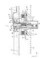
次にコネクタ1の構成について説明する。コネクタ1は、図3及び図4に示すように、インバータ側端子台(本体側部材の一例)30と、モータ側端子台(相手側部材の一例)40と、インナハウジング(ハウジングの一例)50と、インナハウジング50内に保持されるインバータ側端子52と、モータ側端子台40に設けられたモータ側ハウジング60と、モータ側ハウジング60内に保持されるモータ側端子62と、編組線70と、を備える。このうちインバータ側端子台30はインバータ側(上側)に設けられ、モータ側端子台40はモータ側(下側)に設けられている。
Next, the configuration of the
インバータ側端子台30は、図1に示すように、平面に視た大きさがインバータケース10の下側部分よりも小さな部材とされる。インバータ側端子台30には、図6等に示すように、ハウジング取付部32が設けられている。ハウジング取付部32は、インバータ側端子台30を上側として、モータ側ハウジング60と上下方向において重畳している。
As shown in FIG. 1, the inverter-
ハウジング取付部32は、図6等に示すように、略筒状をなしており、その内部に、当該ハウジング取付部32の内壁から内向きに略等しい長さで張り出した2つの張り出し部が設けられている。一方の張り出し部は、ハウジング取付部32の上部開口縁からX−Y平面方向に平行に張り出しており、その下面が係止面32Aとされる。他方の張り出し部は、ハウジング取付部32の内壁の上下方向における略中央位置からX−Y平面方向に平行に張り出しており、その上面が支持面32Bとされる。
As shown in FIG. 6 and the like, the
インナハウジング50は、上下方向を筒軸方向とする略筒状をなしており、上記係止面32A及び上記支持面32Bによってハウジング取付部32に取り付けられている。インナハウジング50内における下部開口側には、雌型端子であるインバータ側端子52が収容されている。インバータ側端子52は、その接続口を下方に向けた形で、インナハウジング50の内壁から延びるランス54によってインナハウジング50内に保持されている。
The
なお、上記したインバータ側端子台30及びインナハウジング50は、いずれも合成樹脂製とされ、金型を用いた射出成形により形成される部材である。インナハウジング50の詳しい構成、及びハウジング取付部32に対するインナハウジング50の取り付け態様については、後で詳しく説明する。
The inverter
インバータ側端子52の上記接続口とは反対側の一部は、インナハウジング50の内壁に沿ってインナハウジング50の上部開口近傍まで延びており、編組線70の一端部と電気的に接続されている。編組線70は、可撓性を有する導電部材であり、インバータ側端子台30内において引き回されている。編組線70におけるインバータ側端子52と接続された端部とは反対側の端部は、インバータと電気的に接続されている。このため、インバータ側端子52には、インバータで変換された交流電源が供給されるようになっている。
A part of the
インバータ側端子台30は、図3及び図4に示すように、その下面がインバータケース10の下部内壁に宛がわれるとともに、インナハウジング50の下側部分がインバータケース10のインバータ側開口部14に挿通された状態で、インバータケース10に対して組付け固定される。なお、インバータ側端子台30では、ハウジング取付部32の下部開口縁がインバータ側端子台30の下面と上下方向において一致している。このため、インバータ側端子台30をインバータケース10に対して組付ける際、ハウジング取付部32がインバータケース10と干渉しないものとなっている。
As shown in FIGS. 3 and 4, the lower surface of the inverter
モータ側端子台40は、図1及び図2に示すように、モータケース20の上側部分に載置される形で配される。モータ側端子台40には、図3及び図4に示すように、略板状をなす本体部42と、本体部42の一部から上下方向に突出する突出部44と、が設けられている。
As shown in FIGS. 1 and 2, the motor
モータ側ハウジング60は、図3及び図4に示すように、モータ側端子台40における突出部44の上側部分に設けられ、上方に開口している。モータ側端子62は、雄型端子であり、上側を接続側としてモータ側ハウジング60内に固定されている。モータ側端子62は、突出部44の下側部分まで延びてモータと電気的に接続されており、インバータで変換された交流電源をモータ側へ供給する。
As shown in FIGS. 3 and 4, the motor-
モータ側端子台40は、図2乃至図4に示すように、その本体部42が、第1シール部材S1を介してモータケース20のモータ側リブ22上に載置されるとともに、その突出部44の下側部分がモータケース20のモータ側開口部24に挿通された状態で、ボルトBによってモータケース20と締結されることで、モータケース20に対して組付け固定される。
As shown in FIGS. 2 to 4, the motor-
なお、上述したようにモータ側端子台40をモータケース20に対して組付ける際、モータ側端子台40の本体部42とモータ側リブ22との間に第1シール部材S1が配されることで、両者の間がシールされる。これにより、本体部42とモータ側リブ22との間(モータケース20内)に水等が浸入することを防止ないし抑制することができる。
As described above, when the motor
インバータケース10とモータケース20の間は、図3及び図4に示すように、モータ側ハウジング60内にインナハウジング50がその下方から嵌め入れられてインバータ側端子52とモータ側端子62とが上下方向(Z軸方向)、換言すればハウジング取付部32における支持面32Bと直交する方向において雄雌嵌合されることで、組付けられる。インバータ側端子52とモータ側端子62とが嵌合されることで、両端子52、62間が電気的に接続される。その結果、インバータとモータとの間が直接接続され、インバータで変換された交流電源がモータに供給される。
Between the
なお、図3に示すように、インバータ側端子52とモータ側端子62とを接続する際、インバータ側リブ12とモータ側端子台40の本体部42との間に第2シール部材S2が配されることで、両者の間がシールされる。これにより、インバータケース10と本体部42との間(インバータ側端子52とモータ側端子62との接続部分)に水等が浸入することを防止ないし抑制することができる。
As shown in FIG. 3, when connecting the
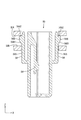
続いて、インナハウジング50の詳しい構成について、図5を参照して説明する。図5に示すように、インナハウジング50の外周面におけるX軸方向両側には、当該外周面から延びる弾性アーム(可撓片の一例)56がそれぞれ設けられている。各弾性アーム56は、可撓性を有しており、インナハウジング50の外周面の上下方向における略中央位置からインナハウジング50の上部開口縁と上下方向において一致する位置まで延びている。
Next, a detailed configuration of the
各弾性アーム56は、図5に示すように、インナハウジング50との間にわずかな隙間を空けて当該インナハウジング50の外周面に沿って上下方向に延びる第1アーム部56Aと、第1アーム部56Aの先端近傍の部位から外側(インナハウジング50の外周面側とは反対側)にわずかに突出する第2アーム部56Bと、を有している。
As shown in FIG. 5, each
図5に示すように、各弾性アーム56の第2アーム部56Bにおける下部には、第1アーム部56Aに対して下方から上方に向かって外側に傾斜する傾斜面56B1がそれぞれ設けられている。さらに、傾斜面56B1と他の面との境界部には曲率が設けられている。また、各弾性アーム56の第2アーム部56Bにおける上部端面56B2は、X−Y平面と平行、即ちハウジング取付部32の係止面32A及び支持面32Bの両者に対して平行とされている。
As shown in FIG. 5, inclined surfaces 56 </ b> B <b> 1 that are inclined outward from the lower side to the upper side with respect to the
なお、各弾性アーム56の第1アーム部56Aのみを含めたインナハウジング50の幅寸法(X軸方向寸法)は、ハウジング取付部32の上部開口よりもわずかに小さいものとされており、各弾性アーム56における第2アーム部56Bまで含めたインナハウジング50の幅寸法(X軸方向寸法)は、ハウジング取付部32の上部開口よりもわずかに大きいものとされている(図5参照)。
In addition, the width dimension (X-axis direction dimension) of the
本実施形態のコネクタ1は以上のような構成であり、続いてハウジング取付部32に対するインナハウジング50の取り付け態様について、図6及び図7を参照して説明する。図6に示すように、インナハウジング50は、内部にインバータ側端子52等が保持されていない状態で、ハウジング取付部32に対してその上方から取り付けられる。インナハウジング50をハウジング取付部32に取り付ける場合、まず、インナハウジング50を、ハウジング取付部32の上方で当該ハウジング取付部32の開口とX−Y平面方向において一致するように位置決めする。
The
次に、インナハウジング50を、ハウジング取付部32内にその上方から挿入する。インナハウジング50は、上下方向において第1アーム部56Aと第2アーム部56Bとの境界部に至るまでハウジング取付部32と干渉することなく、ハウジング取付部32内に挿入される。
Next, the
インナハウジング50をハウジング取付部32内にさらに挿入すると、第2アーム部56Bの下部に設けられた傾斜面56B1が係止面32Aの内側先端部32A1(図6参照)と干渉し、図7に示すように、各第1アーム部56Aが内側(インナハウジング50の外周面側)に撓んだ状態とされる。
When the
各第1アーム部56Aが内側に撓んだ状態からインナハウジング50をハウジング取付部32内にさらに挿入すると、インナハウジング50が傾斜面56B1によってガイドされながら下方へ進行する。ここで、各弾性アーム56において、傾斜面56B1と他の面との間に曲率が設けられていることから、ハウジング取付部32の係止面32Aにおける内側先端部32A1が第2アーム部56Bの傾斜面56B1と干渉する前後においても、インナハウジング50が円滑にガイドされる。
When the
インナハウジング50がさらに下方へ進行することで、各弾性アーム56の第2アーム部56Bにおける上部端面56B2が上下方向において係止面32よりも下方に至ると、第2アーム部56Bがハウジング取付部32に干渉されなくなり、各弾性アーム56はその弾性復帰力によって再び自然状態に復帰する(図5参照)。
When the
各弾性アーム56が再び自然状態に復帰することにより、図5に示すように、各弾性アーム56の第2アーム部56Bがハウジング取付部32の係止面32Aと支持面32Bとの間に入り込んだ状態とされる。この状態では、各弾性アーム56の第2アーム部56Bにおける上部端面56B2が係止面32Aによって係止され、インナハウジング50がハウジング取付部32から上方へ外れることが防止される。
When each
さらにこの状態では、各弾性アーム56の第2アーム部56Bが支持面32Bによって支持されることでインナハウジング50が当該支持面32Bにフローティング支持され、インナハウジング50がハウジング取付部32から下方へ脱落することが防止される。
Further, in this state, the
このようにインナハウジング50が支持面32Bにフローティング支持されることで、インバータ側端子52とモータ側端子62とを嵌合する際に両端子52、62間の相対位置が位置ずれした場合に、インナハウジング50が支持面32Bに沿って摺動し、当該支持面32Bに沿った方向(X−Y平面に沿った方向)における位置ずれを吸収することができる。
When the
以上のような取り付け態様によって、インナハウジング50がハウジング取付部32に取り付けられる。インナハウジング50をハウジング取付部32に取り付けた後、編組線70の一端部と接続されたインバータ側端子62が、インナハウジング50内に取り付けられる。
The
以上説明したように本実施形態に係るコネクタ1では、インナハウジング50をインバータ側端子台30のハウジング取付部32に取り付ける際、第2アーム部56Bの傾斜面56B1によってインナハウジング50が下方(取り付け方向)にガイドされながら第1アーム部56Aが内側に撓むことで、インナハウジング50をハウジング取付部32に取り付けることができる。
As described above, in the
そして、インナハウジング50をハウジング取付部32に取り付けることで、インナハウジング50の各弾性アーム56における第2アーム部56Bを、インバータ側端子台30のハウジング取付部32における係止面32Aに係止させることができる。さらに、当該第2アーム部56Bを、ハウジング取付部32における支持面32Bに支持させることでインナハウジング50を当該支持面32Bにフローティング支持させることができる。このように、インナハウジング50をインバータ側端子台30のハウジング取付部32に容易に取り付けることができる。
Then, by attaching the
ここで、図4等に示すように、インバータ側端子台30は、当該インバータ側端子台30に支持されるインナハウジング50よりも大きな部材とされるため、射出成形する際の熱収縮率や必要となる樹脂量がインナハウジング50よりも大きいものとされる。このため、インバータ側端子台30側に2つの弾性アーム56を設けると、インナハウジング50側に2つの弾性アーム56を設ける場合と比べて弾性アーム56の寸法公差が大きくなり、インナハウジング50の取り付け精度が低下する。
Here, as shown in FIG. 4 and the like, the inverter-
これに対し本実施形態のコネクタ1では、インナハウジング50側にのみ2つの弾性アーム56が設けられるので、インバータ側端子台30側に2つの弾性アーム56を設ける場合と比べて弾性アーム56の寸法公差が小さいものとなり、インバータ側端子52とモータ側端子62の間を嵌合する際に両端子52、62間の相対位置が位置ずれした場合であっても、その位置ずれを効果的に吸収させることができる。その結果、インナハウジング50の取り付け精度を向上させることができる。
On the other hand, in the
このように本実施形態のコネクタ1では、インバータ側端子台30とモータ側端子台40とが嵌合されることでインバータとモータとの間が直接接続される構成において、インバータ側端子台30のハウジング取付部32における支持面32Bにフローティング支持されるインナハウジング50の取り付け精度を向上させることができる。
Thus, in the
また、本実施形態のコネクタ1では、上述したように、インナハウジング50側にのみ2つの弾性アーム56が設けられるので、インナハウジング50側とインバータ側端子台30側との両者に弾性アーム56を設ける場合と比べて、射出成形する際に使用する金型を簡素化することができ、低コスト化を図ることができる。
Further, in the
また、本実施形態のコネクタ1では、インナハウジング50をハウジング取付部32に取り付ける際に、リテーナ部材等の他の部材を必要としないため、他の部材を必要とする構成と比べてインナハウジング50の取り付け作業の簡略化、及び低コスト化を図ることができる。
Moreover, in the
また、本実施形態のコネクタ1では、インバータ側端子52とモータ側端子62とが支持面32Bと直交する方向に雄雌嵌合されることで、インバータ側端子52とモータ側端子62とを嵌合する際に両端子52、62間の相対位置が位置ずれした場合に、雄雌嵌合の嵌合の程度が変動することによって、上下方向(Z軸方向)における位置ずれも吸収することができる。
Moreover, in the
上記の実施形態の変形例を以下に列挙する。
(1)上記の実施形態では、インナハウジングに2つの弾性アームが設けられた構成を例示したが、インナハウジングに3つ以上の弾性アームが設けられた構成であってもよい。
The modifications of the above embodiment are listed below.
(1) In the above embodiment, the configuration in which the inner housing is provided with the two elastic arms is illustrated, but the inner housing may be provided with three or more elastic arms.
(3)上記の実施形態では、インバータ側端子が雌型端子とされ、モータ側端子が雄型端子とされた構成を例示したが、インバータ側端子が雄型端子とされ、モータ側端子が雌型端子とされた構成であってもよい。 (3) In the above embodiment, the inverter side terminal is a female terminal and the motor side terminal is a male terminal. However, the inverter side terminal is a male terminal and the motor side terminal is a female terminal. The structure used as the type | mold terminal may be sufficient.
(4)上記の実施形態では、インバータとモータとの間を接続するコネクタについて例示したが、他の用途に用いるコネクタであってもよい。 (4) In the above embodiment, the connector for connecting the inverter and the motor is exemplified, but the connector may be used for other purposes.
以上、本発明の各実施形態について詳細に説明したが、これらは例示に過ぎず、特許請求の範囲を限定するものではない。特許請求の範囲に記載の技術には、以上に例示した具体例を様々に変形、変更したものが含まれる。 As mentioned above, although each embodiment of this invention was described in detail, these are only illustrations and do not limit a claim. The technology described in the claims includes various modifications and changes of the specific examples illustrated above.
1…コネクタ
10…インバータケース
20…モータケース
30…インバータ側端子台
32…ハウジング取付部
32A…係止面
32B…支持面
40…モータ側端子台
50…インナハウジング
52…インバータ側端子
56…弾性アーム
56A…第1アーム部
56B…第2アーム部
56B1…傾斜面
60…モータ側ハウジング
62…モータ側端子
70…編組線
DESCRIPTION OF
Claims (2)
相手側部材と、
前記係止面に係止された状態で前記支持面にフローティング支持されるハウジングと、
前記ハウジング内に保持される本体側端子と、
前記相手側部材に固定され、前記本体側端子と雄雌嵌合される相手側端子と、を備え、
前記ハウジングの外周面に、前記係止面に係止される複数の可撓片が設けられており、
前記複数の可撓片の各々は前記ハウジングの外周面から延びる弾性アームであり、
前記弾性アームの各々は、前記ハウジングの外周面に沿って延びる第1アーム部と、該第1アーム部から外側に突出するとともに該第1アーム部に対して傾斜する傾斜面が設けられた第2アーム部と、を有し、
前記第2アーム部における前記傾斜面側が前記支持面によって支持されているとともに、前記第2アーム部における前記傾斜面よりも先端側に設けられた上部端面が前記係止面に係止可能とされていることを特徴とするコネクタ。 A main body side member having a locking surface and a support surface;
A mating member;
A housing that is floatingly supported on the support surface in a state of being locked to the locking surface;
A body-side terminal held in the housing;
A mating terminal fixed to the mating member and mated with the main body side terminal;
A plurality of flexible pieces locked to the locking surface are provided on the outer peripheral surface of the housing ,
Each of the plurality of flexible pieces is an elastic arm extending from the outer peripheral surface of the housing,
Each of the elastic arms is provided with a first arm portion extending along an outer peripheral surface of the housing, and an inclined surface that protrudes outward from the first arm portion and is inclined with respect to the first arm portion. Two arm parts,
The inclined surface side of the second arm portion is supported by the support surface, and an upper end surface provided on the distal end side of the inclined surface of the second arm portion can be locked to the locking surface. connector, characterized in that is.
前記本体側部材が前記インバータ側に設けられたインバータ側端子台であるとともに、前記本体側端子が前記インバータと電気的に接続されたインバータ側端子とされ、
前記相手側部材は、前記モータ側に設けられたモータ側端子台であるとともに、前記相手側端子が前記モータと電気的に接続されたモータ側端子とされることを特徴とするコネクタ。 The connector according to claim 1, wherein the connector is connected between the inverter and the motor.
The main body side member is an inverter side terminal block provided on the inverter side, and the main body side terminal is an inverter side terminal electrically connected to the inverter,
The mating member is a motor side terminal block provided on the motor side, and the mating terminal is a motor side terminal electrically connected to the motor.
Priority Applications (1)
| Application Number | Priority Date | Filing Date | Title |
|---|---|---|---|
| JP2013257779A JP6052155B2 (en) | 2013-12-13 | 2013-12-13 | connector |
Applications Claiming Priority (1)
| Application Number | Priority Date | Filing Date | Title |
|---|---|---|---|
| JP2013257779A JP6052155B2 (en) | 2013-12-13 | 2013-12-13 | connector |
Publications (2)
| Publication Number | Publication Date |
|---|---|
| JP2015115250A JP2015115250A (en) | 2015-06-22 |
| JP6052155B2 true JP6052155B2 (en) | 2016-12-27 |
Family
ID=53528863
Family Applications (1)
| Application Number | Title | Priority Date | Filing Date |
|---|---|---|---|
| JP2013257779A Expired - Fee Related JP6052155B2 (en) | 2013-12-13 | 2013-12-13 | connector |
Country Status (1)
| Country | Link |
|---|---|
| JP (1) | JP6052155B2 (en) |
Family Cites Families (2)
| Publication number | Priority date | Publication date | Assignee | Title |
|---|---|---|---|---|
| JP5399804B2 (en) * | 2009-08-03 | 2014-01-29 | 矢崎総業株式会社 | connector |
| JP5594538B2 (en) * | 2011-05-06 | 2014-09-24 | 住友電装株式会社 | Connector for equipment |
-
2013
- 2013-12-13 JP JP2013257779A patent/JP6052155B2/en not_active Expired - Fee Related
Also Published As
| Publication number | Publication date |
|---|---|
| JP2015115250A (en) | 2015-06-22 |
Similar Documents
| Publication | Publication Date | Title |
|---|---|---|
| JP5967063B2 (en) | connector | |
| JP5624180B2 (en) | connector | |
| JP5991260B2 (en) | Connector and wire harness | |
| JP6247604B2 (en) | Waterproof connector | |
| US9905977B2 (en) | Motor terminal, motor terminal assembly having the same, and method of assembling motor using the same | |
| JP2013197096A (en) | Terminal | |
| JP2014086349A (en) | Connector | |
| JP6601092B2 (en) | connector | |
| JP2012234744A (en) | Connector for apparatus | |
| US20160141796A1 (en) | Connector | |
| JP6135502B2 (en) | connector | |
| CN112217017B (en) | Connector with a locking member | |
| JP6052155B2 (en) | connector | |
| JP5407057B2 (en) | connector | |
| JP7098678B2 (en) | Protector and wire harness | |
| JP5062377B1 (en) | Male connector | |
| JP2017098193A (en) | Waterproof connector | |
| JP2016122510A (en) | connector | |
| JP5780181B2 (en) | Connector device | |
| JP2022063764A (en) | connector | |
| JP2022131040A (en) | Wiring harness and connector | |
| JP2013143826A (en) | Electric wire housing body | |
| JP2016201281A (en) | connector | |
| JP2015115252A (en) | Connector | |
| JP2014041730A (en) | Connector unit |
Legal Events
| Date | Code | Title | Description |
|---|---|---|---|
| A621 | Written request for application examination |
Free format text: JAPANESE INTERMEDIATE CODE: A621 Effective date: 20151224 |
|
| A131 | Notification of reasons for refusal |
Free format text: JAPANESE INTERMEDIATE CODE: A131 Effective date: 20160830 |
|
| A977 | Report on retrieval |
Free format text: JAPANESE INTERMEDIATE CODE: A971007 Effective date: 20160831 |
|
| A521 | Request for written amendment filed |
Free format text: JAPANESE INTERMEDIATE CODE: A523 Effective date: 20161012 |
|
| TRDD | Decision of grant or rejection written | ||
| A01 | Written decision to grant a patent or to grant a registration (utility model) |
Free format text: JAPANESE INTERMEDIATE CODE: A01 Effective date: 20161101 |
|
| A61 | First payment of annual fees (during grant procedure) |
Free format text: JAPANESE INTERMEDIATE CODE: A61 Effective date: 20161114 |
|
| R150 | Certificate of patent or registration of utility model |
Ref document number: 6052155 Country of ref document: JP Free format text: JAPANESE INTERMEDIATE CODE: R150 |
|
| LAPS | Cancellation because of no payment of annual fees |