JP6050635B2 - Document reader - Google Patents
Document reader Download PDFInfo
- Publication number
- JP6050635B2 JP6050635B2 JP2012186056A JP2012186056A JP6050635B2 JP 6050635 B2 JP6050635 B2 JP 6050635B2 JP 2012186056 A JP2012186056 A JP 2012186056A JP 2012186056 A JP2012186056 A JP 2012186056A JP 6050635 B2 JP6050635 B2 JP 6050635B2
- Authority
- JP
- Japan
- Prior art keywords
- document
- unit
- reading
- separation
- reading unit
- Prior art date
- Legal status (The legal status is an assumption and is not a legal conclusion. Google has not performed a legal analysis and makes no representation as to the accuracy of the status listed.)
- Active
Links
- 238000000926 separation method Methods 0.000 claims description 56
- 230000001105 regulatory effect Effects 0.000 claims description 6
- 239000011521 glass Substances 0.000 description 23
- 238000012423 maintenance Methods 0.000 description 6
- 238000011144 upstream manufacturing Methods 0.000 description 6
- 238000006243 chemical reaction Methods 0.000 description 4
- 239000000428 dust Substances 0.000 description 2
- 239000000758 substrate Substances 0.000 description 2
- 238000010586 diagram Methods 0.000 description 1
- 238000007599 discharging Methods 0.000 description 1
- 230000001678 irradiating effect Effects 0.000 description 1
- 238000000034 method Methods 0.000 description 1
Images


Classifications
-
- B—PERFORMING OPERATIONS; TRANSPORTING
- B65—CONVEYING; PACKING; STORING; HANDLING THIN OR FILAMENTARY MATERIAL
- B65H—HANDLING THIN OR FILAMENTARY MATERIAL, e.g. SHEETS, WEBS, CABLES
- B65H7/00—Controlling article feeding, separating, pile-advancing, or associated apparatus, to take account of incorrect feeding, absence of articles, or presence of faulty articles
- B65H7/20—Controlling associated apparatus
-
- B—PERFORMING OPERATIONS; TRANSPORTING
- B65—CONVEYING; PACKING; STORING; HANDLING THIN OR FILAMENTARY MATERIAL
- B65H—HANDLING THIN OR FILAMENTARY MATERIAL, e.g. SHEETS, WEBS, CABLES
- B65H1/00—Supports or magazines for piles from which articles are to be separated
- B65H1/04—Supports or magazines for piles from which articles are to be separated adapted to support articles substantially horizontally, e.g. for separation from top of pile
-
- B—PERFORMING OPERATIONS; TRANSPORTING
- B65—CONVEYING; PACKING; STORING; HANDLING THIN OR FILAMENTARY MATERIAL
- B65H—HANDLING THIN OR FILAMENTARY MATERIAL, e.g. SHEETS, WEBS, CABLES
- B65H1/00—Supports or magazines for piles from which articles are to be separated
- B65H1/08—Supports or magazines for piles from which articles are to be separated with means for advancing the articles to present the articles to the separating device
-
- B—PERFORMING OPERATIONS; TRANSPORTING
- B65—CONVEYING; PACKING; STORING; HANDLING THIN OR FILAMENTARY MATERIAL
- B65H—HANDLING THIN OR FILAMENTARY MATERIAL, e.g. SHEETS, WEBS, CABLES
- B65H29/00—Delivering or advancing articles from machines; Advancing articles to or into piles
- B65H29/12—Delivering or advancing articles from machines; Advancing articles to or into piles by means of the nip between two, or between two sets of, moving tapes or bands or rollers
- B65H29/125—Delivering or advancing articles from machines; Advancing articles to or into piles by means of the nip between two, or between two sets of, moving tapes or bands or rollers between two sets of rollers
-
- B—PERFORMING OPERATIONS; TRANSPORTING
- B65—CONVEYING; PACKING; STORING; HANDLING THIN OR FILAMENTARY MATERIAL
- B65H—HANDLING THIN OR FILAMENTARY MATERIAL, e.g. SHEETS, WEBS, CABLES
- B65H29/00—Delivering or advancing articles from machines; Advancing articles to or into piles
- B65H29/12—Delivering or advancing articles from machines; Advancing articles to or into piles by means of the nip between two, or between two sets of, moving tapes or bands or rollers
- B65H29/14—Delivering or advancing articles from machines; Advancing articles to or into piles by means of the nip between two, or between two sets of, moving tapes or bands or rollers and introducing into a pile
-
- B—PERFORMING OPERATIONS; TRANSPORTING
- B65—CONVEYING; PACKING; STORING; HANDLING THIN OR FILAMENTARY MATERIAL
- B65H—HANDLING THIN OR FILAMENTARY MATERIAL, e.g. SHEETS, WEBS, CABLES
- B65H29/00—Delivering or advancing articles from machines; Advancing articles to or into piles
- B65H29/58—Article switches or diverters
-
- B—PERFORMING OPERATIONS; TRANSPORTING
- B65—CONVEYING; PACKING; STORING; HANDLING THIN OR FILAMENTARY MATERIAL
- B65H—HANDLING THIN OR FILAMENTARY MATERIAL, e.g. SHEETS, WEBS, CABLES
- B65H3/00—Separating articles from piles
- B65H3/02—Separating articles from piles using friction forces between articles and separator
- B65H3/06—Rollers or like rotary separators
-
- B—PERFORMING OPERATIONS; TRANSPORTING
- B65—CONVEYING; PACKING; STORING; HANDLING THIN OR FILAMENTARY MATERIAL
- B65H—HANDLING THIN OR FILAMENTARY MATERIAL, e.g. SHEETS, WEBS, CABLES
- B65H31/00—Pile receivers
-
- B—PERFORMING OPERATIONS; TRANSPORTING
- B65—CONVEYING; PACKING; STORING; HANDLING THIN OR FILAMENTARY MATERIAL
- B65H—HANDLING THIN OR FILAMENTARY MATERIAL, e.g. SHEETS, WEBS, CABLES
- B65H5/00—Feeding articles separated from piles; Feeding articles to machines
- B65H5/06—Feeding articles separated from piles; Feeding articles to machines by rollers or balls, e.g. between rollers
- B65H5/068—Feeding articles separated from piles; Feeding articles to machines by rollers or balls, e.g. between rollers between one or more rollers or balls and stationary pressing, supporting or guiding elements
-
- B—PERFORMING OPERATIONS; TRANSPORTING
- B65—CONVEYING; PACKING; STORING; HANDLING THIN OR FILAMENTARY MATERIAL
- B65H—HANDLING THIN OR FILAMENTARY MATERIAL, e.g. SHEETS, WEBS, CABLES
- B65H5/00—Feeding articles separated from piles; Feeding articles to machines
- B65H5/36—Article guides or smoothers, e.g. movable in operation
- B65H5/38—Article guides or smoothers, e.g. movable in operation immovable in operation
-
- G—PHYSICS
- G03—PHOTOGRAPHY; CINEMATOGRAPHY; ANALOGOUS TECHNIQUES USING WAVES OTHER THAN OPTICAL WAVES; ELECTROGRAPHY; HOLOGRAPHY
- G03G—ELECTROGRAPHY; ELECTROPHOTOGRAPHY; MAGNETOGRAPHY
- G03G15/00—Apparatus for electrographic processes using a charge pattern
-
- G—PHYSICS
- G03—PHOTOGRAPHY; CINEMATOGRAPHY; ANALOGOUS TECHNIQUES USING WAVES OTHER THAN OPTICAL WAVES; ELECTROGRAPHY; HOLOGRAPHY
- G03G—ELECTROGRAPHY; ELECTROPHOTOGRAPHY; MAGNETOGRAPHY
- G03G15/00—Apparatus for electrographic processes using a charge pattern
- G03G15/60—Apparatus which relate to the handling of originals
- G03G15/602—Apparatus which relate to the handling of originals for transporting
-
- G—PHYSICS
- G03—PHOTOGRAPHY; CINEMATOGRAPHY; ANALOGOUS TECHNIQUES USING WAVES OTHER THAN OPTICAL WAVES; ELECTROGRAPHY; HOLOGRAPHY
- G03G—ELECTROGRAPHY; ELECTROPHOTOGRAPHY; MAGNETOGRAPHY
- G03G21/00—Arrangements not provided for by groups G03G13/00 - G03G19/00, e.g. cleaning, elimination of residual charge
- G03G21/16—Mechanical means for facilitating the maintenance of the apparatus, e.g. modular arrangements
-
- H—ELECTRICITY
- H04—ELECTRIC COMMUNICATION TECHNIQUE
- H04N—PICTORIAL COMMUNICATION, e.g. TELEVISION
- H04N1/00—Scanning, transmission or reproduction of documents or the like, e.g. facsimile transmission; Details thereof
-
- H—ELECTRICITY
- H04—ELECTRIC COMMUNICATION TECHNIQUE
- H04N—PICTORIAL COMMUNICATION, e.g. TELEVISION
- H04N1/00—Scanning, transmission or reproduction of documents or the like, e.g. facsimile transmission; Details thereof
- H04N1/00519—Constructional details not otherwise provided for, e.g. housings, covers
- H04N1/00538—Modular devices, i.e. allowing combinations of separate components, removal or replacement of components
- H04N1/00541—Modular devices, i.e. allowing combinations of separate components, removal or replacement of components with detachable image reading apparatus
-
- H—ELECTRICITY
- H04—ELECTRIC COMMUNICATION TECHNIQUE
- H04N—PICTORIAL COMMUNICATION, e.g. TELEVISION
- H04N1/00—Scanning, transmission or reproduction of documents or the like, e.g. facsimile transmission; Details thereof
- H04N1/00519—Constructional details not otherwise provided for, e.g. housings, covers
- H04N1/00543—Allowing easy access, e.g. for maintenance or in case of paper jam
-
- H—ELECTRICITY
- H04—ELECTRIC COMMUNICATION TECHNIQUE
- H04N—PICTORIAL COMMUNICATION, e.g. TELEVISION
- H04N1/00—Scanning, transmission or reproduction of documents or the like, e.g. facsimile transmission; Details thereof
- H04N1/00519—Constructional details not otherwise provided for, e.g. housings, covers
- H04N1/00557—Connection or assembly of components or elements
-
- H—ELECTRICITY
- H04—ELECTRIC COMMUNICATION TECHNIQUE
- H04N—PICTORIAL COMMUNICATION, e.g. TELEVISION
- H04N1/00—Scanning, transmission or reproduction of documents or the like, e.g. facsimile transmission; Details thereof
- H04N1/04—Scanning arrangements, i.e. arrangements for the displacement of active reading or reproducing elements relative to the original or reproducing medium, or vice versa
Landscapes
- Engineering & Computer Science (AREA)
- Multimedia (AREA)
- Signal Processing (AREA)
- Mechanical Engineering (AREA)
- Physics & Mathematics (AREA)
- General Physics & Mathematics (AREA)
- Facsimile Scanning Arrangements (AREA)
- Facsimiles In General (AREA)
- Exposure Or Original Feeding In Electrophotography (AREA)
- Electrophotography Configuration And Component (AREA)
- Feeding Of Articles By Means Other Than Belts Or Rollers (AREA)
- Pile Receivers (AREA)
- Sheets, Magazines, And Separation Thereof (AREA)
Description
本発明は原稿の両面を読み取る原稿読取装置に関し、詳しくは一方面を読み取られた原稿の他方面を読み取るための読取ユニットを有する原稿搬送装置を備えた原稿読取装置に関するものである。 The present invention relates to an original reading apparatus that reads both sides of an original, and more particularly to an original reading apparatus that includes an original conveying device having a reading unit for reading the other side of an original that has been read on one side.
従来、両面に画像が形成された両面原稿を読み取る原稿読取装置としては、原稿の表裏を反転する反転機構を有する原稿搬送装置を備え、読取部に原稿を搬送して一方面を読み取った後に反転機構で原稿の表裏を反転させて、再び読取部に原稿を搬送して他方面を読み取るもののほかに、原稿の一方面を読み取る第1の読取部と原稿の他方面を読み取る第2の読取部の、二つの読取部で原稿の両面を読み取るものが知られている。 2. Description of the Related Art Conventionally, as a document reading device that reads a double-sided document with images formed on both sides, a document conveying device having a reversing mechanism for reversing the front and back of the document has been provided. In addition to reversing the front and back sides of the document with the mechanism, transporting the document again to the reading unit and reading the other side, a first reading unit that reads one side of the document and a second reading unit that reads the other side of the document A device that reads both sides of a document with two reading units is known.
このような二つの読取部を備えて原稿の両面を読み取る原稿読取装置において、第1の読取ユニットを原稿読取装置本体側に設けると共に、第2の読取ユニットを原稿搬送装置に形成されたU字状の原稿搬送経路の内側に設けたものがこれまでに知られている。 In an original reading apparatus that includes two reading units and reads both sides of an original, the first reading unit is provided on the main body of the original reading apparatus, and the second reading unit is a U-shape formed on the original conveying apparatus. What is provided in the inside of the original document conveyance path is known.
通常、原稿搬送装置は、ブック用のコンタクトガラスに載置した原稿を読み取るために、原稿読取装置本体の上面に対して開閉自在となっている。そのため原稿搬送装置には、開閉の都度衝撃や振動が少なからず発生する。従って原稿搬送装置側に設けた第2の読取ユニットは、原稿読取装置本体側に設けた第1の読取ユニットに比べて、必然的に高頻度でメンテナンスを行わなければならない。 Usually, the document feeder is openable and closable with respect to the upper surface of the document reader main body in order to read a document placed on a contact glass for a book. For this reason, the document conveying apparatus generates a considerable amount of impact and vibration every time it is opened and closed. Therefore, the second reading unit provided on the side of the document conveying apparatus must inevitably be subjected to maintenance more frequently than the first reading unit provided on the side of the document reading apparatus main body.
上述のような第2の読取ユニットを、原稿搬送装置に形成されたU字状の原稿搬送経路の内側に設けた装置の場合、原稿搬送経路を構成する搬送ガイドが第2の読取ユニットを取り囲んでいるために、メンテナンス等で第2の読取ユニットを取り出すためには、原稿搬送方向に直交する方向(原稿幅方向)、即ち装置のフロント側に第2の読取ユニットを引き出して取り外す必要がある(例えば、特許文献1及び特許文献2参照)。 In the case of the apparatus in which the second reading unit as described above is provided inside the U-shaped document conveyance path formed in the document conveyance device, the conveyance guide constituting the document conveyance path surrounds the second reading unit. Therefore, in order to take out the second reading unit for maintenance or the like, it is necessary to pull out and remove the second reading unit in the direction orthogonal to the document conveying direction (document width direction), that is, the front side of the apparatus. (For example, refer to Patent Document 1 and Patent Document 2).
しかしながら、上記のような第2の読取ユニットを原稿搬送装置のフロント側に引き出す構成とする場合、装置のフロント側の側板にユニット取り外し用の開口を設ける必要があり、装置の強度が著しく低下するという難点があった。 However, when the second reading unit is pulled out to the front side of the document conveying apparatus, it is necessary to provide an opening for removing the unit on the side plate on the front side of the apparatus, and the strength of the apparatus is significantly reduced. There was a difficulty.
また、第2の読取ユニットを原稿搬送装置に装着する際には、原稿幅方向に長尺な読取ユニットを装置フロント側から挿入するため、開口スペースが狭い上にリア側が見えず、読取ユニットの取り付け及び位置決めが難しいのみならず、第2の読取ユニットのCCD基板と装置の制御基板を結ぶ配線の取り外し作業が煩わしいという問題があった。 Further, when the second reading unit is mounted on the document conveying device, since the reading unit elongated in the document width direction is inserted from the front side of the device, the opening space is narrow and the rear side cannot be seen, and the reading unit Not only is the attachment and positioning difficult, there is a problem that the work of removing the wiring connecting the CCD substrate of the second reading unit and the control substrate of the apparatus is troublesome.
本発明は、上記状況に鑑みて、原稿搬送装置に形成されたU字状の原稿搬送経路の内側に設けられた読取ユニットの着脱を容易にしてメンテナンス性を向上させることが可能な原稿読取装置を提供することを目的とする。 SUMMARY OF THE INVENTION In view of the above situation, the present invention provides an original reading apparatus that can easily attach and detach a reading unit provided inside a U-shaped original conveying path formed in an original conveying apparatus and improve maintainability. The purpose is to provide.
上記の課題を解決するため、本発明は、原稿を載置する給紙トレイと、原稿を読み取るための読取部と、該読取部で読み取られた原稿を収納する排紙トレイと、前記給紙トレイから前記読取部を介して前記排紙トレイに至るU字状の原稿搬送経路と、前記給紙トレイ上の原稿を分離して給紙する給紙ローラと該給紙ローラに圧接する分離部材とからなる分離手段と、該分離手段の下流に配置される原稿送りローラ対と、前記U字状の原稿搬送経路の内側に配置される読取ユニットと、を備える原稿読取装置において、前記給紙トレイの下流側に設けられ、前記給紙トレイ上に載置される原稿の先端を整合する規制壁と、該規制壁に連続して配設され、少なくとも前記給紙トレイから前記原稿送りローラ対までの前記原稿搬送経路を形成するガイド部材と、を設け、前記規制壁と前記ガイド部材、及び前記分離部材を、一体の分離ガイドユニットとして構成すると共に該分離ガイドユニットを前記原稿搬送経路に対して着脱自在に構成し、前記分離ガイドユニットを取り外した前記原稿搬送経路の開口部より、前記読取ユニットをU字状の前記原稿搬送経路の内側から取り外し可能とすることを特徴とする原稿読取装置を提供する。 In order to solve the above problems, the present invention provides a paper feed tray on which a document is placed, a reading unit for reading a document, a paper discharge tray for storing a document read by the reading unit, and the paper feed A U-shaped document conveyance path from the tray through the reading unit to the sheet discharge tray, a sheet feeding roller that separates and feeds documents on the sheet feeding tray, and a separation member that presses the sheet feeding roller In the document reading apparatus, the sheet feeding unit includes: a separating unit including: a pair of document feeding rollers disposed downstream of the separating unit; and a reading unit disposed inside the U-shaped document conveying path. A regulating wall provided on the downstream side of the tray for aligning the leading edges of the documents placed on the sheet feeding tray, and arranged continuously from the regulating wall, and at least from the sheet feeding tray to the pair of document feeding rollers To form the document transport path up to A separating member, and the regulating wall, the guide member, and the separating member are configured as an integral separating guide unit, and the separating guide unit is configured to be detachable from the document conveyance path, and the separating There is provided an original reading apparatus characterized in that the reading unit can be removed from the inside of the U-shaped original conveying path through an opening of the original conveying path from which the guide unit is removed.
ここで、前記分離ガイドユニットには箱状の凹部を形成し、該箱状の凹部に前記分離部材を配置することを特徴とする。 Here, the separation guide unit is formed with a box-shaped recess, and the separation member is disposed in the box-shaped recess.
また、前記分離ガイドユニットが、前記箱状の凹部の開口部を覆う蓋部を備え、該蓋部は前記分離ガイドユニットに対して着脱又は回動自在に取り付けられることを特徴とする。 The separation guide unit may include a lid that covers the opening of the box-shaped recess, and the lid may be detachably or pivotably attached to the separation guide unit.
本発明の原稿読取装置によれば、装置の強度を低下させることなしに原稿搬送装置内の読取ユニットへのアクセスを容易にすると共に、読取ユニットの取り出しスペースを大きく確保したために、読取ユニットの着脱を容易にし、メンテナンス性を向上させることが可能となる。 According to the document reading apparatus of the present invention, it is easy to access the reading unit in the document conveying apparatus without reducing the strength of the apparatus, and a large space for taking out the reading unit is secured. It is possible to facilitate the maintenance and improve the maintainability.
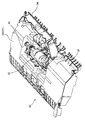
以下、本発明に係る原稿搬送装置を備える原稿読取装置を説明する。図1は原稿読取装置本体及び原稿搬送装置の全体構成を示す断面図である。 Hereinafter, a document reading apparatus provided with a document conveying device according to the present invention will be described. FIG. 1 is a cross-sectional view illustrating the entire configuration of the document reading apparatus main body and the document conveying apparatus.
図1に示すように原稿読取装置は、原稿読取装置本体Hと原稿を搬送する原稿搬送装置Aで構成されており、原稿搬送装置Aは原稿読取装置本体Hに図示しないヒンジを介して取り付けられている。なお、前記ヒンジは原稿読取装置本体Hの上面に対して原稿搬送装置Aを開閉自在に支持する。 As shown in FIG. 1, the document reading apparatus includes a document reading apparatus main body H and a document conveying apparatus A that conveys a document. The document conveying apparatus A is attached to the document reading apparatus main body H via a hinge (not shown). ing. The hinge supports the document feeder A so that it can be opened and closed with respect to the upper surface of the document reader main body H.
原稿読取装置本体Hには、原稿搬送装置Aによってコンタクトガラス1a上面を搬送される原稿の片面を読み取るための第1の読取ユニット2が設けられている。また、原稿搬送装置Aには本体Hのコンタクトガラス1a上面を通過した原稿の他面を読み取るための第2の読取ユニット3(読取ユニット)が設けられている。
The document reading device main body H is provided with a
そして、原稿搬送装置Aは、原稿読取装置本体Hの上面を開放するように本体Hに対して開閉自在に取り付けられており、本体Hのコンタクトガラス1bに載置された原稿を第1の読取ユニット2を移動させて読み取るように構成されている。
The document feeder A is attached to the body H so as to be openable and closable so as to open the upper surface of the document reading apparatus body H, and the document placed on the
原稿読取装置本体Hに設けられた第1の読取ユニット2は、光源、複数のミラー、レンズ、光電変換素子(CCD)を含む光電変換手段が一体化されたユニットとなっている。そして、第1のコンタクトガラス1aを介して光源からの光を搬送される原稿に照射し、その反射光をミラーで反射させてレンズを介してCCDを含む光電変換手段により光電変換して原稿画像を読み取る。また、第1の読取ユニット2は、副走査方向に移動することによって、原稿搬送装置Aを開閉して第2のコンタクトガラス1b上に載置されたブック物等の厚い原稿画像を読み取る。
The
原稿搬送装置Aは、図1に示すように複数枚の原稿が載置可能な給紙トレイ10と、読み取られた原稿を収納する排紙トレイ11が備えられている。給紙トレイ10は排紙トレイ11の上方に重なるように配置されており、給紙トレイ10の下流側には、給紙トレイ10上に載置された原稿の先端を整合する規制壁32が、給紙トレイ10から後述するU字状の原稿搬送経路12へ繋がるように設けられている。
As shown in FIG. 1, the document feeder A includes a
原稿搬送経路12は、給紙トレイ10から排紙トレイ11へ至るU字状の経路であり、図1に示すように給紙トレイ10上の原稿が繰り出される給紙口12aからレジストローラ対16に至る上流側の経路と、レジストローラ対16から第1のコンタクトガラス1aに至る湾曲した中間の経路と、第1のコンタクトガラス1aから排紙ローラ対19の位置する排紙口12bに至る下流側の経路から構成されている。
The
図3に原稿搬送経路12の概略を示す。図3に示すように、原稿搬送経路12は、原稿を案内するための上下に配置されたガイド部材から形成されている。このガイド部材は、U字状の内側に位置する内側ガイド121と外側に位置する外側ガイド122から構成される。
FIG. 3 shows an outline of the
この原稿搬送経路12には、給紙トレイ10に載置され規制壁32で先端を整合された原稿に当接して、この原稿を繰り出すための繰出ローラ13と、繰り出された原稿を給送する給紙ローラ14と、給紙ローラ14に圧接して原稿を1枚に分離する分離ローラ(分離部材)15と、この給紙ローラ14及び分離ローラ15からなる分離手段により1枚に分離されて給送される原稿の先端を突き当てて整合した後に下流側に送る、レジストローラ16A、16B(図2参照)からなるレジストローラ対(原稿送りローラ対)16と、第1のコンタクトガラス1aの上流側に配置された第1の搬送ローラ対17と、第1のコンタクトガラス1aの下流側に配置された第2の搬送ローラ対18と、第2の搬送ローラ対18の下流側に配置されて排紙トレイ11に原稿を排紙する排紙ローラ対19と、が設けられている。
The
なお、繰出ローラ13、給紙ローラ14、レジストローラ16Aは、原稿搬送装置Aの給紙カバー41と共にユニット化されて給紙カバーユニット40を形成している。また、分離ローラ15と、原稿搬送経路12の上流側の内側ガイド121(ガイド面31)と、給紙トレイ10の規制壁32もユニット化されて、分離ガイドユニット30を形成している。この給紙カバーユニット40及び分離ガイドユニット30についての詳細は後述する。
The
原稿搬送装置Aには、第1の読取ユニット2で読み取られる原稿面と反対側の原稿面を読み取るための第2の読取ユニット3が設けられている。この第2の読取ユニット3はU字状の原稿搬送経路12の内側の領域に配置されている。そして、第2の読取ユニット3には、その排紙方向の端部に第3のコンタクトガラス20が設けられている。第3のコンタクトガラス20は、第2の搬送ローラ対18と排紙ローラ対19との間に配置されて原稿搬送経路12のガイド部材(内側ガイド121)の一部として機能し、第3のコンタクトガラス20面を通過する原稿を第2の読取ユニット3で読み取るように構成されている。
The document feeder A is provided with a
このような構成によって、給紙トレイ10上の原稿を繰出ローラ13で繰り出し、分離手段(給紙ローラ14、分離ローラ15)によって1枚に分離する。そして、1枚に分離された原稿をレジストローラ対16で整合した後に第1の搬送ローラ対17にて第1のコンタクトガラス1aに搬送する。その後、第1のコンタクトガラス1aを通過した原稿を第2の搬送ローラ対18にて第3のコンタクトガラス20に搬送し、排紙ローラ19で排紙トレイ11に排紙する。この原稿を搬送する過程において、原稿が第1のコンタクトガラス1aを通過するときに第1の読取ユニット2によって原稿の表面が読み取られ、原稿が第3のコンタクトガラス20を通過するときに第2の読取ユニット3によって原稿の裏面が読み取られる。
With such a configuration, the document on the
次に、第2の読取ユニット3内の読取部の構成について説明する。図2は、原稿搬送経路12及び第2の読取ユニット3周辺を拡大して示す拡大断面図である。第2の読取ユニット3は、コンタクトガラス20を通過する原稿に光を照射するためのLED及び導光体からなる光源21と、原稿からの反射光を所定の方向に導く複数のミラー24、25、26、27と、複数のミラー24、25、26、27により導かれた反射光を集束するレンズ28と、レンズ28により集束された光を光電変換するCCD(光電変換素子)29とを備えている。
Next, the configuration of the reading unit in the
そして、第3のコンタクトガラス20を介して光源21から発せられる光を原稿に照射し、その反射光を複数のミラー24、25、26、27で反射させ、レンズ28を介してCCD29により光電変換して原稿画像を読み取る。
Then, the document is irradiated with light emitted from the
このように、上記原稿読取装置では、第1のコンタクトガラス1aを通過する原稿の表面の画像を第1の読取ユニット2で読み取り、第3のコンタクトガラス20を通過する原稿の裏面の画像を第2の読取ユニット3で読み取るので、両面原稿の画像読取時間を大幅に短縮することができる。
As described above, in the document reading apparatus, the
次に、給紙カバーユニット40及び分離ガイドユニット30の詳細について具体的に説明する。図4は、給紙カバーユニット40を開放状態にして分離ガイドユニット30を取り外した状態を示す斜視図である。また、図5及び図6は分離ガイドユニット30の斜視図であり、図5は分離ガイドユニット30の蓋部を閉じた状態、図6は蓋部を開いた状態をそれぞれ示している。
Next, details of the paper
図2及び図4に示すように、原稿搬送装置Aは、給紙口12a、原稿搬送経路12、及び第2の読取ユニット3等を覆う給紙カバー41を備えている。この給紙カバー41は、繰出ローラ13、給紙ローラ14、レジストローラ16A、及び原稿搬送経路12の上流から中間部の外側ガイド122と一体に形成されて、給紙カバーユニット40を構成している。この給紙カバーユニット40は、回動ピン42によって開閉可能に枢支されており、図4に示すように装置上側に回動させることにより上流側の原稿搬送経路12を開放することができる。
As shown in FIGS. 2 and 4, the document conveying apparatus A includes a
一方、給紙カバーユニット40の内側には、内部に分離ローラ15を備えた分離ガイドユニット30が設けられている。分離ガイドユニット30は、原稿搬送装置Aの、第2の読取ユニット3の上部に設けられた開口部123(図4参照)に着脱自在に配置されている。なお通常時は、分離ガイドユニット30は開口123にセットされて、上方から装置側板にビス(図示せず)で固定されている。
On the other hand, a
図2に示すように、分離ガイドユニット30の給紙口12a側外面は、給紙トレイ10に載置された原稿の先端を整合する規制壁32として機能する。また、分離ガイドユニット30の上面は、原稿搬送経路12の上流側の内側ガイド121(ガイド面31)を構成している。このガイド面31は、図2に示すように少なくとも給紙トレイ10からレジストローラ対16に亘って設けられている。
As shown in FIG. 2, the outer surface of the
このように、給紙トレイ10からレジストローラ対16に至るまでの内側ガイド121を分離ガイドユニット30と共に取り外しできるため、第2の読取ユニット3にアクセスするための開口123を広く確保することができる。
Thus, the
そこで、第2の読取ユニット3をメンテナンス等のために取り外す際は、図4に示すように、まず回動ピン42を中心に給紙カバーユニット40を回動させて原稿搬送経路12を開放する。次いで、開放された原稿搬送経路12から分離ガイドユニット30を取り外す。そして、分離ガイドユニット30が取り外された開口部123から第2の読取ユニット3を引き出して取り外し、メンテナンス等を行う。
Therefore, when removing the
なお、図4に示されるように本実施例では、分離ガイドユニット30を取り外した際に一方のレジストローラ16Bが読取ユニット3の上方にある。したがって、読取ユニットを取り外す際にレジストローラ16Bのシャフトの片側を側板から取り外し、取り外したレジストローラ16Bの片側を原稿給紙方向に若干移動させることで、さらに読取ユニット3の取り外しが容易になる。また、他の手段としてはレジストローラ16Bを内側ガイド121に取り付け、分離ガイドユニット30と一体で取り外した後に、読取ユニット3を取り外すようにしてもよい。これによって、さらに読取ユニット3の取り外しが容易になる。
As shown in FIG. 4, in this embodiment, when the
分離ガイドユニット30は、側部と底部を備えて内部に分離ローラ15及びその駆動シャフトを搭載する空間を有する箱状の凹部33と、この箱状の凹部33の上部開口を覆う蓋部34とから構成される。蓋部34は、図6に示すように凹部33に回動自在に軸支されており、凹部33を開閉することができる。また蓋部34の上面は、分離ガイドユニット30の上面と共にガイド面31を構成している。さらに蓋部34には、凹部33に配置された分離ローラ15を露出するための開口34aが設けられており、分離ローラ15は、この開口34aを通して給紙カバーユニット40側の給紙ローラ14と圧接する。
The
このように、本発明の原稿搬送装置Aでは、分離ガイドユニット30を箱状の凹部33と蓋部34から構成することにより、給紙ローラ14と分離ローラ15からなる分離手段から第2の読取ユニット3を隔絶している。これにより、分離手段での分離の際に発生する紙粉やローラ削りカス等が、読取ユニット3に落下することがない。この分離に伴う紙粉やローラ削りカス等は、分離ガイドユニット30の凹部33内に溜まるため、分離ガイドユニット30のメンテナンス時に蓋部34を開いて容易に除去することができる。
As described above, in the document conveying apparatus A according to the present invention, the
なお、ここでは分離ガイドユニット30の凹部33が蓋部34を回動自在に軸支する構成としたが、蓋部34は凹部33に対して着脱自在に取り付けられる構成としても良い。
Here, the
以上、詳細に説明したように、本発明の原稿読取装置によれば、装置の強度を低下させることなしに原稿搬送装置内の読取ユニットへのアクセスを容易にすると共に、読取ユニットの取り出しスペースを大きく確保したために、読取ユニットの着脱を容易にし、メンテナンス性を向上させることが可能となる。 As described above in detail, according to the document reading apparatus of the present invention, it is easy to access the reading unit in the document conveying apparatus without reducing the strength of the apparatus, and the space for taking out the reading unit is reduced. Since it is ensured to a large extent, it is possible to easily attach and detach the reading unit and to improve maintainability.
A 原稿搬送装置A
H 原稿読取装置本体
3 第2の読取ユニット(読取ユニット)
10 給紙トレイ
11 排紙トレイ
12 原稿搬送経路
123 開口部
14 給紙ローラ
15 分離ローラ(分離部材)
16 レジストローラ対(原稿送りローラ対)
30 分離ガイドユニット
31 ガイド面(ガイド部材)
32 規制壁
33 箱状の凹部
34 蓋部
A Document feeder A
H Document reading apparatus
DESCRIPTION OF
16 Registration roller pair (document feed roller pair)
30
32
Claims (2)
前記給紙トレイの下流側に設けられ、前記給紙トレイ上に載置される原稿の先端を整合する規制壁と、該規制壁に連続して配設され、少なくとも前記給紙トレイから前記原稿送りローラ対までの前記原稿搬送経路を形成するガイド部材と、を設け、
前記規制壁と前記ガイド部材、及び前記分離部材を、一体の分離ガイドユニットとして構成すると共に該分離ガイドユニットを前記原稿搬送経路に対して着脱自在に構成し、
前記分離ガイドユニットを取り外した前記原稿搬送経路の開口部より、前記読取ユニットをU字状の前記原稿搬送経路の内側から取り外し可能とし、
前記分離ガイドユニットに箱状の凹部を形成し、該箱状の凹部に前記分離部材を配置する、ことを特徴とする原稿読取装置。 A paper feed tray for placing a document, a reading unit for reading the document, a paper discharge tray for storing the document read by the reading unit, and the paper discharge tray from the paper feed tray through the reading unit A separating unit comprising a U-shaped document conveying path to the sheet, a sheet feeding roller for separating and feeding the document on the sheet feeding tray, and a separating member pressed against the sheet feeding roller, and downstream of the separating unit In a document reading apparatus comprising: a pair of document feed rollers disposed in a document; and a reading unit disposed inside the U-shaped document conveyance path;
A regulating wall provided on the downstream side of the sheet feeding tray and aligning a leading edge of the document placed on the sheet feeding tray, and arranged continuously from the regulating wall, and at least from the sheet feeding tray to the document A guide member that forms the document conveyance path to the pair of feed rollers, and
The restriction wall, the guide member, and the separation member are configured as an integral separation guide unit, and the separation guide unit is configured to be detachable from the document conveyance path,
The reading unit can be removed from the inside of the U-shaped original conveying path from the opening of the original conveying path from which the separation guide unit has been removed ,
A document reading apparatus comprising: a box-shaped recess formed in the separation guide unit; and the separation member disposed in the box-shaped recess .
Priority Applications (7)
| Application Number | Priority Date | Filing Date | Title |
|---|---|---|---|
| JP2012186056A JP6050635B2 (en) | 2012-08-27 | 2012-08-27 | Document reader |
| IN1763DEN2015 IN2015DN01763A (en) | 2012-08-27 | 2013-08-23 | |
| MYPI2015700597A MY189061A (en) | 2012-08-27 | 2013-08-23 | Document reading device |
| CN201380050524.5A CN104704802B (en) | 2012-08-27 | 2013-08-23 | Original document reading apparatus |
| US14/424,191 US9272868B2 (en) | 2012-08-27 | 2013-08-23 | Document reading device |
| EP13832383.7A EP2890099B1 (en) | 2012-08-27 | 2013-08-23 | Document reading device |
| PCT/JP2013/072564 WO2014034561A1 (en) | 2012-08-27 | 2013-08-23 | Document reading device |
Applications Claiming Priority (1)
| Application Number | Priority Date | Filing Date | Title |
|---|---|---|---|
| JP2012186056A JP6050635B2 (en) | 2012-08-27 | 2012-08-27 | Document reader |
Related Child Applications (1)
| Application Number | Title | Priority Date | Filing Date |
|---|---|---|---|
| JP2016228692A Division JP6339162B2 (en) | 2016-11-25 | 2016-11-25 | Document reader |
Publications (2)
| Publication Number | Publication Date |
|---|---|
| JP2014045301A JP2014045301A (en) | 2014-03-13 |
| JP6050635B2 true JP6050635B2 (en) | 2016-12-21 |
Family
ID=50183374
Family Applications (1)
| Application Number | Title | Priority Date | Filing Date |
|---|---|---|---|
| JP2012186056A Active JP6050635B2 (en) | 2012-08-27 | 2012-08-27 | Document reader |
Country Status (7)
| Country | Link |
|---|---|
| US (1) | US9272868B2 (en) |
| EP (1) | EP2890099B1 (en) |
| JP (1) | JP6050635B2 (en) |
| CN (1) | CN104704802B (en) |
| IN (1) | IN2015DN01763A (en) |
| MY (1) | MY189061A (en) |
| WO (1) | WO2014034561A1 (en) |
Families Citing this family (6)
| Publication number | Priority date | Publication date | Assignee | Title |
|---|---|---|---|---|
| JP2014201369A (en) * | 2013-04-01 | 2014-10-27 | 船井電機株式会社 | Sheet transport device |
| JP6314962B2 (en) * | 2015-11-24 | 2018-04-25 | コニカミノルタ株式会社 | Double-sided image reading apparatus and image forming apparatus |
| JP6756970B2 (en) * | 2016-03-22 | 2020-09-16 | セイコーエプソン株式会社 | Media feeder and image reader |
| JP6520840B2 (en) | 2016-06-27 | 2019-05-29 | コニカミノルタ株式会社 | Image reading apparatus, image forming apparatus, and image forming system |
| CN108628117A (en) * | 2017-03-16 | 2018-10-09 | 柯尼卡美能达办公系统研发(无锡)有限公司 | Image forming apparatus |
| JP7297452B2 (en) | 2019-01-18 | 2023-06-26 | キヤノン株式会社 | sheet feeding device, image reading device, image forming device |
Family Cites Families (14)
| Publication number | Priority date | Publication date | Assignee | Title |
|---|---|---|---|---|
| JP3388114B2 (en) * | 1996-11-15 | 2003-03-17 | 京セラミタ株式会社 | Document feeder |
| JP3310183B2 (en) * | 1996-11-15 | 2002-07-29 | 京セラミタ株式会社 | Document guide mechanism |
| JP2001233491A (en) * | 2000-02-24 | 2001-08-28 | Murata Mach Ltd | Automatic sheet carrying device |
| JP2002182437A (en) | 2000-12-11 | 2002-06-26 | Nisca Corp | Automatic document feeder including image reading means and image reader |
| JP4294655B2 (en) * | 2006-05-09 | 2009-07-15 | ニスカ株式会社 | Image reading device |
| JP4839207B2 (en) * | 2006-12-27 | 2011-12-21 | ニスカ株式会社 | Document conveying apparatus and image reading apparatus |
| JP4887137B2 (en) | 2006-12-28 | 2012-02-29 | ニスカ株式会社 | Image reading device |
| JP5090004B2 (en) * | 2007-01-31 | 2012-12-05 | ニスカ株式会社 | Image reading device |
| JP5215054B2 (en) * | 2008-06-17 | 2013-06-19 | ニスカ株式会社 | Image reading system |
| JP4697617B2 (en) * | 2009-04-01 | 2011-06-08 | Necアクセステクニカ株式会社 | Automatic document feeder |
| JP4847556B2 (en) * | 2009-05-19 | 2011-12-28 | 株式会社沖データ | Paper conveying apparatus, image reading apparatus, and image forming apparatus |
| JP5387840B2 (en) * | 2009-09-28 | 2014-01-15 | 村田機械株式会社 | Image reading device |
| JP4962748B2 (en) * | 2010-01-29 | 2012-06-27 | コニカミノルタビジネステクノロジーズ株式会社 | Image reading device |
| JP5843530B2 (en) * | 2011-09-09 | 2016-01-13 | ニスカ株式会社 | Document reader |
-
2012
- 2012-08-27 JP JP2012186056A patent/JP6050635B2/en active Active
-
2013
- 2013-08-23 MY MYPI2015700597A patent/MY189061A/en unknown
- 2013-08-23 WO PCT/JP2013/072564 patent/WO2014034561A1/en active Application Filing
- 2013-08-23 US US14/424,191 patent/US9272868B2/en active Active
- 2013-08-23 IN IN1763DEN2015 patent/IN2015DN01763A/en unknown
- 2013-08-23 CN CN201380050524.5A patent/CN104704802B/en not_active Expired - Fee Related
- 2013-08-23 EP EP13832383.7A patent/EP2890099B1/en active Active
Also Published As
| Publication number | Publication date |
|---|---|
| EP2890099B1 (en) | 2019-07-10 |
| MY189061A (en) | 2022-01-24 |
| EP2890099A4 (en) | 2016-04-06 |
| US20150203309A1 (en) | 2015-07-23 |
| WO2014034561A1 (en) | 2014-03-06 |
| CN104704802A (en) | 2015-06-10 |
| EP2890099A1 (en) | 2015-07-01 |
| JP2014045301A (en) | 2014-03-13 |
| US9272868B2 (en) | 2016-03-01 |
| CN104704802B (en) | 2018-05-11 |
| IN2015DN01763A (en) | 2015-05-29 |
Similar Documents
| Publication | Publication Date | Title |
|---|---|---|
| JP6050635B2 (en) | Document reader | |
| US10091372B2 (en) | Medium feeding device and image reading apparatus | |
| JP5170145B2 (en) | Image reading device | |
| JP4294655B2 (en) | Image reading device | |
| JP2007067605A (en) | Image reading apparatus | |
| JP2002344695A (en) | Image reader | |
| JP6339162B2 (en) | Document reader | |
| JP4331668B2 (en) | Document reader | |
| JP2008048190A (en) | Image reader | |
| JP4580750B2 (en) | Image forming apparatus | |
| JP4596033B2 (en) | Document reader | |
| JP5951446B2 (en) | Paper feeder | |
| JP4253993B2 (en) | Image reading device | |
| JP3682578B2 (en) | Intermediate transfer device | |
| JP4941677B2 (en) | Automatic document feeder and document reader having the same | |
| JP2005104661A (en) | Image reader | |
| JP5686157B2 (en) | Image reading device | |
| JP5024677B2 (en) | Automatic document feeder and document reader | |
| JP2002274694A (en) | Document feeder | |
| JP2001106371A (en) | Sheet conveying device | |
| JP2007124013A (en) | Draft feeder and image reading apparatus | |
| JP3985770B2 (en) | Image reading device | |
| JP5177720B2 (en) | Image reading apparatus and image forming apparatus | |
| JP5793368B2 (en) | Sheet conveying apparatus and image reading apparatus | |
| JP2004196463A (en) | Printer |
Legal Events
| Date | Code | Title | Description |
|---|---|---|---|
| A621 | Written request for application examination |
Free format text: JAPANESE INTERMEDIATE CODE: A621 Effective date: 20150806 |
|
| A131 | Notification of reasons for refusal |
Free format text: JAPANESE INTERMEDIATE CODE: A131 Effective date: 20160510 |
|
| A521 | Request for written amendment filed |
Free format text: JAPANESE INTERMEDIATE CODE: A523 Effective date: 20160727 |
|
| A131 | Notification of reasons for refusal |
Free format text: JAPANESE INTERMEDIATE CODE: A131 Effective date: 20160819 |
|
| A521 | Request for written amendment filed |
Free format text: JAPANESE INTERMEDIATE CODE: A523 Effective date: 20161012 |
|
| TRDD | Decision of grant or rejection written | ||
| A01 | Written decision to grant a patent or to grant a registration (utility model) |
Free format text: JAPANESE INTERMEDIATE CODE: A01 Effective date: 20161027 |
|
| A61 | First payment of annual fees (during grant procedure) |
Free format text: JAPANESE INTERMEDIATE CODE: A61 Effective date: 20161125 |
|
| R150 | Certificate of patent or registration of utility model |
Ref document number: 6050635 Country of ref document: JP Free format text: JAPANESE INTERMEDIATE CODE: R150 |
|
| S111 | Request for change of ownership or part of ownership |
Free format text: JAPANESE INTERMEDIATE CODE: R313115 |
|
| R350 | Written notification of registration of transfer |
Free format text: JAPANESE INTERMEDIATE CODE: R350 |
|
| R250 | Receipt of annual fees |
Free format text: JAPANESE INTERMEDIATE CODE: R250 |
|
| R250 | Receipt of annual fees |
Free format text: JAPANESE INTERMEDIATE CODE: R250 |
|
| R250 | Receipt of annual fees |
Free format text: JAPANESE INTERMEDIATE CODE: R250 |
|
| R250 | Receipt of annual fees |
Free format text: JAPANESE INTERMEDIATE CODE: R250 |
|
| R250 | Receipt of annual fees |
Free format text: JAPANESE INTERMEDIATE CODE: R250 |