JP6046172B2 - Method for providing volumetric flow - Google Patents
Method for providing volumetric flow Download PDFInfo
- Publication number
- JP6046172B2 JP6046172B2 JP2014561315A JP2014561315A JP6046172B2 JP 6046172 B2 JP6046172 B2 JP 6046172B2 JP 2014561315 A JP2014561315 A JP 2014561315A JP 2014561315 A JP2014561315 A JP 2014561315A JP 6046172 B2 JP6046172 B2 JP 6046172B2
- Authority
- JP
- Japan
- Prior art keywords
- liquid phase
- pressure
- viscosity
- drop
- dimensional object
- Prior art date
- Legal status (The legal status is an assumption and is not a legal conclusion. Google has not performed a legal analysis and makes no representation as to the accuracy of the status listed.)
- Active
Links
- 238000000034 method Methods 0.000 title claims description 51
- 239000000463 material Substances 0.000 claims description 93
- 239000007791 liquid phase Substances 0.000 claims description 29
- 230000008569 process Effects 0.000 claims description 29
- 238000004519 manufacturing process Methods 0.000 claims description 16
- 230000008859 change Effects 0.000 claims description 11
- 238000003860 storage Methods 0.000 claims description 11
- 230000002265 prevention Effects 0.000 claims description 9
- 238000012937 correction Methods 0.000 claims description 7
- 230000001419 dependent effect Effects 0.000 claims description 5
- 238000007599 discharging Methods 0.000 claims description 4
- 230000006978 adaptation Effects 0.000 claims description 3
- 238000005096 rolling process Methods 0.000 claims description 2
- 238000005259 measurement Methods 0.000 description 12
- 230000033001 locomotion Effects 0.000 description 6
- 239000004033 plastic Substances 0.000 description 6
- 230000000694 effects Effects 0.000 description 4
- 238000001746 injection moulding Methods 0.000 description 3
- 238000002360 preparation method Methods 0.000 description 3
- 239000007787 solid Substances 0.000 description 3
- 230000006641 stabilisation Effects 0.000 description 3
- 238000011105 stabilization Methods 0.000 description 3
- 230000008901 benefit Effects 0.000 description 2
- 230000000903 blocking effect Effects 0.000 description 2
- 239000000843 powder Substances 0.000 description 2
- 238000012935 Averaging Methods 0.000 description 1
- 238000009825 accumulation Methods 0.000 description 1
- 230000033228 biological regulation Effects 0.000 description 1
- 230000015572 biosynthetic process Effects 0.000 description 1
- 238000006243 chemical reaction Methods 0.000 description 1
- 238000000354 decomposition reaction Methods 0.000 description 1
- 230000007423 decrease Effects 0.000 description 1
- 238000001514 detection method Methods 0.000 description 1
- 238000010586 diagram Methods 0.000 description 1
- 238000005516 engineering process Methods 0.000 description 1
- 238000001125 extrusion Methods 0.000 description 1
- 239000012530 fluid Substances 0.000 description 1
- 238000010348 incorporation Methods 0.000 description 1
- 238000002347 injection Methods 0.000 description 1
- 239000007924 injection Substances 0.000 description 1
- 238000007689 inspection Methods 0.000 description 1
- 239000007788 liquid Substances 0.000 description 1
- 238000000691 measurement method Methods 0.000 description 1
- 230000007246 mechanism Effects 0.000 description 1
- 239000000155 melt Substances 0.000 description 1
- 238000002844 melting Methods 0.000 description 1
- 230000008018 melting Effects 0.000 description 1
- 238000012986 modification Methods 0.000 description 1
- 230000004048 modification Effects 0.000 description 1
- 229920001296 polysiloxane Polymers 0.000 description 1
- 239000012254 powdered material Substances 0.000 description 1
- 238000004886 process control Methods 0.000 description 1
- 239000002994 raw material Substances 0.000 description 1
- 239000012925 reference material Substances 0.000 description 1
- 238000007789 sealing Methods 0.000 description 1
- 230000000087 stabilizing effect Effects 0.000 description 1
- 238000006467 substitution reaction Methods 0.000 description 1
- 239000000758 substrate Substances 0.000 description 1
- 238000012360 testing method Methods 0.000 description 1
- 229920001169 thermoplastic Polymers 0.000 description 1
- 239000004416 thermosoftening plastic Substances 0.000 description 1
- 230000007704 transition Effects 0.000 description 1
- 238000013519 translation Methods 0.000 description 1
- 239000011345 viscous material Substances 0.000 description 1
Images


Classifications
-
- B—PERFORMING OPERATIONS; TRANSPORTING
- B29—WORKING OF PLASTICS; WORKING OF SUBSTANCES IN A PLASTIC STATE IN GENERAL
- B29C—SHAPING OR JOINING OF PLASTICS; SHAPING OF MATERIAL IN A PLASTIC STATE, NOT OTHERWISE PROVIDED FOR; AFTER-TREATMENT OF THE SHAPED PRODUCTS, e.g. REPAIRING
- B29C64/00—Additive manufacturing, i.e. manufacturing of three-dimensional [3D] objects by additive deposition, additive agglomeration or additive layering, e.g. by 3D printing, stereolithography or selective laser sintering
- B29C64/10—Processes of additive manufacturing
- B29C64/106—Processes of additive manufacturing using only liquids or viscous materials, e.g. depositing a continuous bead of viscous material
- B29C64/112—Processes of additive manufacturing using only liquids or viscous materials, e.g. depositing a continuous bead of viscous material using individual droplets, e.g. from jetting heads
-
- B—PERFORMING OPERATIONS; TRANSPORTING
- B29—WORKING OF PLASTICS; WORKING OF SUBSTANCES IN A PLASTIC STATE IN GENERAL
- B29C—SHAPING OR JOINING OF PLASTICS; SHAPING OF MATERIAL IN A PLASTIC STATE, NOT OTHERWISE PROVIDED FOR; AFTER-TREATMENT OF THE SHAPED PRODUCTS, e.g. REPAIRING
- B29C64/00—Additive manufacturing, i.e. manufacturing of three-dimensional [3D] objects by additive deposition, additive agglomeration or additive layering, e.g. by 3D printing, stereolithography or selective laser sintering
- B29C64/10—Processes of additive manufacturing
- B29C64/165—Processes of additive manufacturing using a combination of solid and fluid materials, e.g. a powder selectively bound by a liquid binder, catalyst, inhibitor or energy absorber
-
- B—PERFORMING OPERATIONS; TRANSPORTING
- B29—WORKING OF PLASTICS; WORKING OF SUBSTANCES IN A PLASTIC STATE IN GENERAL
- B29C—SHAPING OR JOINING OF PLASTICS; SHAPING OF MATERIAL IN A PLASTIC STATE, NOT OTHERWISE PROVIDED FOR; AFTER-TREATMENT OF THE SHAPED PRODUCTS, e.g. REPAIRING
- B29C64/00—Additive manufacturing, i.e. manufacturing of three-dimensional [3D] objects by additive deposition, additive agglomeration or additive layering, e.g. by 3D printing, stereolithography or selective laser sintering
- B29C64/30—Auxiliary operations or equipment
- B29C64/386—Data acquisition or data processing for additive manufacturing
- B29C64/393—Data acquisition or data processing for additive manufacturing for controlling or regulating additive manufacturing processes
-
- B—PERFORMING OPERATIONS; TRANSPORTING
- B33—ADDITIVE MANUFACTURING TECHNOLOGY
- B33Y—ADDITIVE MANUFACTURING, i.e. MANUFACTURING OF THREE-DIMENSIONAL [3-D] OBJECTS BY ADDITIVE DEPOSITION, ADDITIVE AGGLOMERATION OR ADDITIVE LAYERING, e.g. BY 3-D PRINTING, STEREOLITHOGRAPHY OR SELECTIVE LASER SINTERING
- B33Y10/00—Processes of additive manufacturing
Description
(関連の出願)
本出願は、2012年03月14日付けドイツ特許出願第 10 2012 004 988.9 号の優先権を主張し、その開示内容は、本出願の対象としても本明細書に援用されるものとする。
(Related application)
This application claims the priority of German Patent Application No. 10 2012 004 988.9 dated 14 March 2012, the disclosure content of which is incorporated herein by reference.
(発明の分野)
本発明は、請求項1の上位概念部に記載した、3次元物体を製造するために、順次続く滴から成る容積流を提供するための方法に関する。
(Field of Invention)
The present invention relates to a method for providing a volumetric flow of successive drops to produce a three-dimensional object as described in the superordinate conception of claim 1.
この種の方法は、下記特許文献1から公知であり、そこでは、一反応成分の滴が放出され、基板上にもたらされた一基本反応成分と接触され、それにより、変化する材料特性を有する3次元物品が層状に作り上げられる。この際、一方の材料特性から他方の材料特性への漸進的な移行が行われる物品部分が得られる。測定された層厚に依存し、場合により製造過程中に変化する処理材料の粘度に留意することなく、必要に応じて滴の大きさを制御することができる。 A method of this kind is known from US Pat. No. 6,057,056, in which a drop of one reactive component is released and contacted with one basic reactive component brought on the substrate, thereby changing the material properties. The three-dimensional article it has is made up in layers. In this case, an article part is obtained in which a gradual transition from one material property to the other material property takes place. Depending on the measured layer thickness, the drop size can be controlled as needed without paying attention to the viscosity of the treatment material, which may vary during the manufacturing process.
下記特許文献2から、射出成形技術では既知の可塑化ユニットを、材料の液相の生成のために圧力を加えることのできる材料蓄積器に連結させることが公知である。作成空間内で目的物支持体上に物体を作成するためにその材料は、放出開口部を介して滴の形で放出され、この際、材料の付着力が原因で、高圧を加える必要があり、また多くの場合は高温を加える必要もある。 It is known from US Pat. No. 6,057,056 that a plasticizing unit known in injection molding technology is connected to a material accumulator that can be pressurized to produce a liquid phase of the material. In order to create an object on the object support in the creation space, the material is ejected in the form of a drop through the ejection opening, with high pressure being applied due to the adhesion of the material In many cases, it is also necessary to apply a high temperature.
この装置においては、大量生産により入手可能であり通常は射出成形において使用される材料を用いるというプラスチック部品製造の利点と、個数1個や小バッチサイズのためのプラスチック部品を製造するという可能性とが兼ね備えられている。従って射出成形加工された部品の特性と類似の特性を有する部品を、工具(型工具)を用いずに製造することができる。 This equipment has the advantage of manufacturing plastic parts that can be obtained by mass production and usually used in injection molding, and the possibility of manufacturing plastic parts for one piece or small batch size. Is combined. Therefore, a part having characteristics similar to those of the injection-molded part can be manufactured without using a tool (mold tool).
例えばサンプル部品のような、そのような個別部品や小バッチサイズの部品を製造するためには、他の製造方法も既知であり、これらの製造方法は、プロトタイピングやラピッドマニュファクチュアリングとの概念のもと広く既知である。そのような部品の製造は、工具なしで、即ち型工具を用いずに、多くの場合は3Dデータから幾何学形状を生成することに基づいている。これらの幾何学形状は、極めて異なる形式により、例えばレーザを用いた熱導入による粉末層の溶融のような対応する手段や、粉末材料の異なる結合形式による圧力法のような生成システムや、或いはまた所謂溶融押し出し成形法によっても製造される。 Other manufacturing methods are also known for producing such individual parts or small batch size parts, for example sample parts, which are not in the concept of prototyping or rapid manufacturing. Originally widely known. The production of such parts is often based on generating geometry from 3D data without tools, i.e. without using mold tools. These geometries can be produced in very different forms, for example by corresponding means such as melting of the powder layer by heat introduction using a laser, production systems such as pressure methods by different forms of bonding of powder materials, or alternatively It is also produced by a so-called melt extrusion method.
実際には、上記特許文献2から公知の方法による製造においては、1つの部品のために比較的長い作成時間が必要であることが分かった。材料圧力発生器内、従ってシステム内にある溶融された材料(質量体 Masse)は、確かに幾何学形状の仕様によりできるだけ少なく保たれるが、他方において材料は、少なすぎてもよくなく、その理由は、そうでなければ放出開口部の各開口部が、滴の放出に際し、圧力レベルに対して決定的に動的な影響を及ぼし、該圧力レベルに材料圧力レギュレータの慣性が追従できないためである。他方において、放出されるプラスチック量は、圧力発生器内の液状化された材料の温度や、材料の圧力や、放出ノズルの幾何学形状や、放出開口部の絞り(Blende)の開口時間及びストロークや、全滞留時間により影響される溶融された材料の粘度などのパラメータ(複数)に依存する。更にプラスチックの構造粘性により、せん断速度が大きいと粘度は減少し、このことは、滴サイズと、該滴サイズの、既にもたらされた滴との融合の傾向(Neigung)とに対して影響をもつ。 In fact, it has been found from the above-mentioned Patent Document 2 that a relatively long production time is required for one part in the production by a known method. The melted material (mass Masse) in the material pressure generator and thus in the system is certainly kept as low as possible due to the geometry specifications, while on the other hand the material can be too little, This is because each opening of the discharge opening has a decisive dynamic effect on the pressure level when the drop is discharged, and the inertia of the material pressure regulator cannot follow the pressure level. is there. On the other hand, the amount of plastic released depends on the temperature of the liquefied material in the pressure generator, the pressure of the material, the geometry of the discharge nozzle, the opening time and stroke of the outlet opening (Blende). And depends on parameters such as the viscosity of the melted material affected by the total residence time. In addition, due to the structural viscosity of the plastic, the viscosity decreases at higher shear rates, which has an effect on the drop size and the tendency of the drop size to fuse with the already produced drops. Have.
従来技術においては、1つのノズルからの単位時間あたりの材料放出量が決定されるという測定方法が既知である。その値は、g/10minにおいて表わされ、この際、プラスチックは、タペットを用い、2.095mmの直径を有するノズルを通して押し出される。重り部材により必要な力が加えられる。値の表示には、常に検査温度と、使用された基準材料(Nennmasse)とが表示されなくてはならない。この方法は、DIN EN ISO 1133 により定義されている。メルトフローレートに応じ、そのように検出されるMFI値(メルトフローインデックス値)の決定では、プラスチックの流動性は、定義された稼働点においてのみ検出される。この際、特に滞留時間に依存してプロセスパラメータが変化する場合の流動性の変化は、考慮されない。 In the prior art, a measurement method is known in which the amount of material discharged per unit time from one nozzle is determined. The value is expressed in g / 10 min, where the plastic is extruded through a nozzle with a diameter of 2.095 mm using a tappet. Necessary force is applied by the weight member. The value display must always indicate the inspection temperature and the reference material used (Nennmasse). This method is defined by DIN EN ISO 1133. In determining the MFI value (melt flow index value) so detected, depending on the melt flow rate, the fluidity of the plastic is detected only at defined operating points. In this case, the change in fluidity is not taken into account, particularly when the process parameters change depending on the residence time.
前記従来技術から出発し、本発明の基礎となる課題は、一定の非連続的な容積流を達成するための方法を提供することである。 Starting from said prior art, the problem underlying the present invention is to provide a method for achieving a constant discontinuous volume flow.
前記課題は、請求項1の特徴を有する方法により解決される。
即ち本発明の一視点により、出発状態で液相にあるか又は液相へ液状化することのできる硬化可能な材料から3次元物体を製造するために、順次続く滴から成る容積流を提供する方法であって、材料蓄積部へ前記材料の液相をもたらすステップと、前記材料蓄積部内の前記材料の液相に対して圧力を発生させるステップと、作成空間内に3次元物体を作り上げるために、サイクル作動可能な放出開口部から前記材料を滴の形で放出するステップとを含むこと、前記材料の液相は、温度に依存した粘度を有すること、少なくとも1つのプロセスパラメータが、3次元物体の製造中に、それ以外のプロセスパラメータの維持のもと、滴サイズの適合のために追従制御されること、前記材料の液相の粘度の変化が連続的に検知されること、及び、前記粘度に変化のある場合には、前記材料蓄積部内の前記圧力が、前記少なくとも1つのプロセスパラメータとして、前記材料の液相の粘度の変化時に、それ以外のプロセスパラメータの維持のもと、制御回路を用い、予め定められた滴サイズを保つために追従制御され、前記圧力は、搬送要素により加えられ、更に測定量としての、放出される滴ごとの該搬送要素の平均的な移動速度が、前記制御回路の調整量へ換算されることを特徴とする方法が提供される。
尚、本願の特許請求の範囲に付記されている図面参照符号は、専ら本発明の理解の容易化のためのものであり、図示の形態への限定を意図するものではないことを付言する。
The object is solved by a method having the features of claim 1.
That is, according to one aspect of the present invention, a volume flow of successive drops is provided to produce a three-dimensional object from a curable material that is in the liquid phase or can be liquefied into the liquid phase in the starting state. A method of providing a liquid phase of the material to a material storage unit; generating a pressure against the liquid phase of the material in the material storage unit; and creating a three-dimensional object in a creation space Discharging the material in the form of drops from a cycle operable discharge opening, the liquid phase of the material has a temperature dependent viscosity, and at least one process parameter is a three-dimensional object During the production of the process, the other process parameters are maintained and the follow-up control is performed to adapt the drop size, the change in the viscosity of the liquid phase of the material is continuously detected, and the previous When there is a change in the viscosity, the pressure in the material accumulating unit is controlled by the control circuit while maintaining the other process parameters when the viscosity of the liquid phase of the material changes as the at least one process parameter. To keep a predetermined drop size, the pressure is applied by the carrier element, and the average moving speed of the carrier element per ejected drop as a measured quantity is A method is provided which is converted into an adjustment amount of the control circuit.
It should be noted that the reference numerals attached to the claims of the present application are only for facilitating the understanding of the present invention, and are not intended to limit the illustrated embodiment.
本発明において、以下の形態が可能である。In the present invention, the following modes are possible.
(形態1)出発状態で液相にあるか又は液相へ液状化することのできる硬化可能な材料から3次元物体を製造するために、順次続く滴から成る容積流を提供する方法であって、材料蓄積部へ前記材料の液相をもたらすステップと、前記材料蓄積部内の前記材料の液相に対して圧力を発生させるステップと、作成空間内に3次元物体を作り上げるために、サイクル作動可能な放出開口部から前記材料を滴の形で放出するステップとを含むこと、前記材料の液相は、温度に依存した粘度を有すること、少なくとも1つのプロセスパラメータが、3次元物体の製造中に、それ以外のプロセスパラメータの維持のもと、滴サイズの適合のために追従制御されること、前記材料の液相の粘度の変化が連続的に検知されること、及び、前記粘度に変化のある場合には、前記材料蓄積部内の前記圧力が、前記少なくとも1つのプロセスパラメータとして、前記材料の液相の粘度の変化時に、それ以外のプロセスパラメータの維持のもと、制御回路を用い、予め定められた滴サイズを保つために追従制御され、前記圧力は、搬送要素により加えられ、更に測定量としての、放出される滴ごとの該搬送要素の平均的な移動速度が、前記制御回路の調整量へ換算されること。(Mode 1) A method for providing a volumetric flow of successive drops to produce a three-dimensional object from a curable material that is in a liquid phase or can be liquefied to a liquid phase in a starting state. A step of bringing the liquid phase of the material into the material storage section; a step of generating a pressure against the liquid phase of the material in the material storage section; and a cycle operation to create a three-dimensional object in the creation space Discharging the material in the form of droplets from a simple discharge opening, the liquid phase of the material having a temperature-dependent viscosity, and at least one process parameter during manufacture of the three-dimensional object , Under the control of other process parameters, follow-up control for drop size adaptation, continuous detection of changes in the liquid phase viscosity of the material, and changes in the viscosity Ah In this case, the pressure in the material accumulating unit is determined in advance by using a control circuit while maintaining the other process parameters when the viscosity of the liquid phase of the material changes as the at least one process parameter. The pressure is applied by the transport element to maintain a given drop size, and the average moving speed of the transport element for each ejected drop as a measured quantity is adjusted by the control circuit. To be converted into a quantity.
(形態2)一定の滴容積の追従制御のための測定量は、動的にローリング方法において決定されることが好ましい。(Mode 2) It is preferable that the measurement amount for tracking control of a constant drop volume is dynamically determined in the rolling method.
(形態3)前記搬送要素は、前記材料の液相を前記材料蓄積部へ搬送するスクリュであることが好ましい。(Form 3) It is preferable that the said conveyance element is a screw which conveys the liquid phase of the said material to the said material storage part.
(形態4)前記搬送要素は、漏れ流のある逆流防止部を有し、該漏れ流は、制御において修正ファクタの決定により考慮されることが好ましい。(Embodiment 4) It is preferable that the conveying element has a backflow prevention unit having a leakage flow, and the leakage flow is taken into account by determining a correction factor in the control.
(形態5)レギュレータは、比例レギュレータであり、特性値は、比例制御アルゴリズムを用いて追従制御されることが好ましい。(Mode 5) The regulator is a proportional regulator, and the characteristic value is preferably subject to follow-up control using a proportional control algorithm.
(形態6)測定量の検出の際に、装置及び材料に固有の限界値が予め定められるか又は予め計算され、該限界値を超過した場合には、装置故障が検知されることが好ましい。(Mode 6) When detecting the measurement amount, it is preferable that a limit value unique to the device and the material is determined or calculated in advance, and if the limit value is exceeded, a device failure is detected.
本発明に従い、プロセスに依存する(prozessrelative)目下のスタート構造粘性が出発点又は基準点において決定され、そして修正量として、プロセス調整要素を用い、滴サイズに関して修正が行われる。好ましくは、調整量は、材料蓄積部内の圧力であり、この際、測定量として、好ましくは、放出される滴ごとの、圧力を発生させる搬送要素の平均的な移動速度が検出され、その変化が、それ以外のプロセスパラメータが固定されている場合には、修正制御量(Korrekturregelgroesse)として圧力に対して提供される。選択的(代替的)に、好ましくは固体ジョイントが使用される放出開口部ないし絞りの、サイクル時間(Taktzeit)ないし閉鎖時間tB、又はサイクル運動sBないしストローク(作動距離 Hub)を、調整量(制御量 Stellgroesse)として使用することもできる。基本的に、材料温度θも調整量として適しているが、材料温度θは、その反応において遥かに緩慢であり、部分的には非線形であるので、レギュレータをそれに対応して構成するのは明らかに困難である。このようなレギュレータは、強いD要素をもつか、又はファジーレギュレータとして稼働されなくてはならないだろう。 In accordance with the present invention, the current start structure viscosity, which is process dependent, is determined at the starting point or reference point, and a correction is made with respect to the drop size using the process adjustment factor as the correction amount. Preferably, the adjustment amount is the pressure in the material accumulating section, and at this time, the average moving speed of the conveying element that generates the pressure is preferably detected as the measurement amount, and the change is detected. However, when the other process parameters are fixed, the correction control amount (Korrekturregelgroesse) is provided for the pressure. Optionally (alternatively), the cycle time (Taktzeit) or the closing time t B , or the cycle movement s B or the stroke (working distance Hub) of the discharge opening or throttling, preferably using a solid joint, is adjusted by an adjustment amount (Control amount Stellgroesse) can also be used. Basically, the material temperature θ is also suitable as an adjustment quantity, but it is clear that the material temperature θ is much slower in the reaction and partly non-linear so that the regulator is configured accordingly. It is difficult to. Such a regulator would have a strong D element or would have to be operated as a fuzzy regulator.
制御(レギュレーション)により、独立して測定されたモデル基準点に関し、例えば生材料のバッチ(チャージ Charge)の変動による、一般的な構造粘性の妨害影響ないし差異を補償することができる。類似の妨害影響は、材料蓄積部内の材料の滞留時間によっても発生する可能性がある。 Control (regulation) makes it possible to compensate for general structural viscosity disturbance effects or differences, for example due to variations in batches of raw materials (charges), with respect to independently measured model reference points. Similar disturbing effects can also occur due to the residence time of the material in the material reservoir.
好ましくは、圧力は、閉鎖要素として逆流防止部が装着されている、例えば射出スクリュのような搬送要素により加えられる。このような逆流防止部は、漏れ流をもつ可能性があり、該漏れ流は、修正ファクタにより、制御アルゴリズムの特性値決定の際に考慮可能である。 Preferably, the pressure is applied by a conveying element, such as an injection screw, which is equipped with a backflow prevention part as a closing element. Such a backflow prevention unit may have a leakage flow, and the leakage flow can be taken into account when determining the characteristic value of the control algorithm by a correction factor.
更なる利点は、下位請求項、並びに実施例の以下の説明から明らかになる。 Further advantages will become apparent from the subclaims as well as the following description of the embodiments.
以下、本発明を、図面に図示した実施例に基づいて詳細に説明する。 Hereinafter, the present invention will be described in detail based on embodiments shown in the drawings.
以下、有利な実施例の詳細な説明である。 The following is a detailed description of an advantageous embodiment.
さて、本発明が添付の図面に関連して例示として詳細に説明される。この際、以下の実施例は、発明のコンセプトを特定の装置に限定すべきではない単なる例示に関するものである。本発明を詳細に説明する前に、本発明が装置の各々の構成部品並びに各々の方法ステップに限定されるものではないことを指摘しておくが、それはそれらの構成部品並びに方法が変更可能なためである。またここで使われている用語は、特別な実施形態を説明するためだけに定められており、限定として使われるものではない。それに加え、本明細書又は本請求項で単数形又は不定冠詞が使われる場合には、それらの要素は複数形であってもよいものとするが、それは全脈絡において明らかに単数形又は不定冠詞でなくてはならない場合は別である。(尚、これに対応し、和文訳文において単数は、複数をも表現しているものとする。) The present invention will now be described in detail by way of example with reference to the accompanying drawings. In this regard, the following examples are merely illustrative, which should not limit the inventive concept to a specific device. Before describing the present invention in detail, it should be pointed out that the present invention is not limited to each component of the apparatus and each method step, which can be varied. Because. Also, the terminology used herein is provided for the purpose of describing particular embodiments only and is not intended to be used as a limitation. In addition, where the singular or indefinite article is used in this specification or in the claims, the element may be plural, but it is clearly singular or indefinite in all contexts. This is not the case. (It should be noted that, in correspondence with this, the singular also expresses the plural in the Japanese translation.)
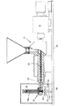
図1及び図2による方法フローを説明する前に、先ず、硬化可能な材料から3次元物体50又は所定の部品を製造するための図3による装置について説明する。出発状態で液相にあるか又は液状化(流動化 verfluessigen)することのできる材料が、滴70を順次的(シーケンシャル)に放出することにより3次元物体50を製造するために用いられる。このことは、例えば、個々の滴70が順次的に放出ユニット12の放出開口部12bから放出されることにより行うことができ、従って層状(層的)に3次元物体50が、作成空間(造形空間 Bauraum)20内で駆動ユニット16により放出開口部12bに対して相対的に可動の目的物支持体13上に作られる。硬化可能な材料は、例えばシリコーンのような可塑化された材料や、熱可塑性プラスチックのような可塑化可能な材料や、粉状の材料であってもよい。これらの材料は、射出成形法において普通に入手可能であり従って比較的有利な材料であるが、その理由は、特別なラピッドプロトタイピング用の材料を必要としないためである。また材料は、熱のもと可逆的に溶融可能であり、従ってリサイクル可能な材料とすることもできる。任意の他の材料も、これらの材料が当該装置により可塑化可能であり、とりわけ少なくとも1つの放出ユニット12により放出可能である場合には使用することができる。
Before describing the method flow according to FIGS. 1 and 2, first the apparatus according to FIG. 3 for producing a three-
材料は、機械テーブル15上に配設された調製ユニット11内で可塑化ないし調製され、圧力発生ユニット10により圧力が加えられる。圧力pは、材料温度θ又は放出開口部12bのサイクル時間(Taktzeit)tB又はサイクル運動(Taktbewegung)sBと同様に、滴70の形成態様を、従って製造すべき3次元物体50の品質を決定する。滴の所望の容積は、特に0.01〜1mm3の範囲内にある。放出開口部12bの直径は、特に1mm以下であり、好ましくは、ほぼ0.1mmである。0.1mmの直径を有する所謂点状注入口を介して材料(質量体 Masse)を搬送する搬送要素の100cm/sという至って通常の搬送速度では、面を通過する容積流で10000m/sの値が得られる。このことは、構造粘性材料において10000m/sに至るまでの流動速度を有する前面層流(laminarer Quellfluss)をもたらすことになる。
The material is plasticized or prepared in a
材料蓄積部12c内にある材料の液相は、駆動部12aにより操作され、放出開口部12bを介して3次元物体50に向かって放出可能である。放出開口部12bには、絞り(Blende)として、好ましくは、上記特許文献3による固体ジョイント(Festkoerpergelenk)を使用することができる。
The liquid phase of the material in the material storage unit 12c is operated by the driving
処理される材料は、一般的に所謂非ニュートン流体である。その構造粘性ηは、温度、圧力、温度下の滞留時間、出発固形物の乾燥度などの任意のプロセス設定値(プロセス調整値)に強く依存する。ところがCADモデルから計算された成形すべき部品の層構造は、好ましくは、一定の滴サイズを前提とする。しかし構造粘性は、逆比例して滴サイズと関連するので、3次元物体50の作成時間中に構造粘性の一時的な変化を補償すること、ないしバッチ変動分に関して最初から設定(調整)することも必要である。そのためには、以下の方法が使用される。
The material to be treated is generally a so-called non-Newtonian fluid. Its structural viscosity η is strongly dependent on any process set value (process adjustment value) such as temperature, pressure, residence time under temperature, dryness of the starting solid. However, the layer structure of the part to be molded calculated from the CAD model preferably assumes a constant drop size. However, since the structural viscosity is inversely related to the droplet size, it is necessary to compensate for temporary changes in the structural viscosity during the creation time of the three-
順次続く滴から成る、好ましくは一定の非連続的な容積流の提供を保証するために、材料の液相が材料蓄積部12cへもたらされる。材料蓄積部12c内の材料の液相に対して圧力pが加えられる。この圧力pのもと材料は、滴70の形で、サイクル作動可能(サイクル的に開閉可能 taktbar)な放出開口部12bから放出され、それにより作成空間20内に3次元物体50を作り上げることができる。この際、液相は、温度θを有する。
In order to ensure the provision of a preferably non-continuous volume flow consisting of successive drops, a liquid phase of the material is brought to the material reservoir 12c. A pressure p is applied to the liquid phase of the material in the material accumulation unit 12c. Under this pressure p, the material is discharged in the form of
容積流を一定に保つために、圧力p、又は放出開口部12bのサイクル時間tB若しくはサイクル運動sB、又は温度θを含んだプロセスパラメータのうちの1つが、材料の液相の粘度の変化時には、それ以外のプロセスパラメータの維持のもと、追従制御(後追い制御 geregelt nachgefuehrt)される。この目的のために、図1によるステップ100では、そのために必要な複数のパラメータが測定され、即ち特に、圧力p(t0)と、絞りを流れる理論的に計算された通流容積vD(t0)と、逆流防止部27の遮断リングを流れる漏れ容積vL(t0)と、材料の温度θとが測定される。更に補足的に又は選択的(代替的)に、秒単位の滴の数たる周波数f、搬送要素の移動距離s、放出開口部12bのサイクル時間tB若しくはサイクル運動sB、搬送用のスクリュ26が収容されている調製ユニットの(スクリュ)横断面積AS、放出開口部12bの直径dDを測定することもできる。
In order to keep the volume flow constant, one of the process parameters including pressure p or cycle time t B or cycle motion s B of discharge opening 12b, or temperature θ is the change in the liquid phase viscosity of the material. Sometimes, follow-up control (follow-up control geregelt nachgefuehrt) is performed while maintaining other process parameters. For this purpose, in
以下、搬送要素(スクリュ26)により発生される圧力pを調整量(制御量 Stellgroesse)とした一定の滴容積の制御について説明する。因みに上述のように、放出開口部12bのサイクル時間tB、サイクル運動sB、又は温度θも、同様に、別のプロセスパラメータがそれ以外で固定されている場合には、制御回路の調整量として使用することができる。 Hereinafter, control of a constant droplet volume using the pressure p generated by the conveying element (screw 26) as an adjustment amount (control amount Stellgroesse) will be described. Incidentally, as described above, the cycle time t B , the cycle motion s B , or the temperature θ of the discharge opening 12b is similarly adjusted when the other process parameters are fixed otherwise. Can be used as
下記数式1で表わされる部品作成のスタート(基準)時点(即ちn0個の滴が時間t0内に構成される)において、理論的な粘度の代替値として、基準特性値(対照特性値 Referenzkennzahl)が構成され、この際、t0は、この時点の後にn0個の滴が放出された時点であり、測定インターバルt0の任意の整数倍である時間の経過後の時点tにおいて、下記数式2で表わされる: The reference characteristic value (reference characteristic value Referenzkennzahl) is used as an alternative value for the theoretical viscosity at the start (reference) time of the part production represented by the following formula 1 (that is, n 0 drops are formed within time t 0 ). ), Where t 0 is the time when n 0 drops have been released after this time, and at time t after the passage of any integer multiple of the measurement interval t 0 Represented by Equation 2:
(数式1)

(数式2)
線形に近似されたプロセス環境において、時点tにおける全滴容積vDは、絞り開口関数tB(t)のもと、ハーゲン・ポアズイユ(Hagen-Poiseuille)の法則により下記数式3で表わされる: In a linearly approximated process environment, the total drop volume v D at time t is expressed by the following equation 3 according to the Hagen-Poiseuille law under the aperture opening function t B (t):
(数式3)
滴容積は全作成プロセスにわたって一定であるべきであり、即ち以下の関係が成り立つべきであり、 The drop volume should be constant throughout the entire production process, ie the following relationship should hold:
上記数式3から下記数式4が得られ、 The following formula 4 is obtained from the above formula 3,
(数式4)
一定の絞り開口関数tB(t)=tB(t0)により下記数式5が得られ、 The following expression 5 is obtained by a constant aperture function t B (t) = t B (t 0 ),
(数式5)
従って、設定(調整)された圧力と、場合により変化する相対的な粘度特性値との間の直接的な比例関係が、可能な滴容積一定化レギュレータのための関係として得られる。 Thus, a direct proportional relationship between the set (adjusted) pressure and the optionally changing relative viscosity characteristic value is obtained as a relationship for a possible drop volume stabilizing regulator.
他方、圧力発生スクリュにおいて逆流防止部が理想的な密封状況を有する場合には(ある時点から)時点t0に至るまでの時間インターバル、ないしtとt−t0との間の時間インターバルにおいて放出された材料容積は、対応するスクリュ移動距離を検出することにより測定される。個々の滴の平均的な容積VT(t)は、対応するインターバルt0において放出された滴の数n0を用いた割算により、下記数式6から得られる: On the other hand, when the backflow prevention part has an ideal sealing state in the pressure generating screw, it is discharged in a time interval from a certain time point to a time point t 0 or a time interval between t and t−t 0. The measured material volume is measured by detecting the corresponding screw travel distance. The average volume V T (t) of an individual drop is obtained from Equation 6 below by division using the number n 0 of drops released at the corresponding interval t 0 :
(数式6)
測定時点t0及びtにおける滴容積一定化(Tropfenvolumenkonstanz)の要求により下記数式7が得られる: The following equation 7 is obtained according to the requirement of the drop volume stabilization (Tropfenvolumenkonstanz) at the measurement times t 0 and t:
(数式7)
この際、スクリュ移動距離の測定により計算される特性値(Kennzahl)は、下記数式8により表わされる: At this time, the characteristic value (Kennzahl) calculated by measuring the screw moving distance is expressed by the following Equation 8.
(数式8)
関数f(p(t))は、実際には、処理される材料のpVT特性マップ(圧力と比容積と温度の相互関係を示す線図)を介して定義されているにもかかわらず、上記数式7と上記数式5との間の関係の直接的な比較が、測定された特性値K(t)による圧力の追従制御を用い、良好な滴容積一定化制御(Tropfenvolumenkonstanzregelung)を可能とすることが分かった。 Even though the function f (p (t)) is actually defined via the pVT characteristic map of the material being processed (the diagram showing the correlation between pressure, specific volume and temperature), A direct comparison of the relationship between Equation 7 and Equation 5 above allows for good drop volume stabilization control (Tropfenvolumenkonstanzregelung) using pressure follow-up control with measured characteristic value K (t). I understood.
1つの滴のためのスクリュ移動距離は極めて小さく、実際の装置内では更に逆流防止部の遮断リングの漏れにより多くの場合誤りを含む可能性があるので、比較的多数の滴にわたり10以上から100以上のn0個の滴について平均化が行われるべきであろう。従って時間的に不連続の複数のt0間隔(t0 Abschnitten)において、スクリュ移動距離の変化が、所定数n0個の滴にわたって観察される。 The screw travel distance for a single drop is very small and may be more likely to be erroneous due to leaks in the backflow prevention shut-off ring in an actual device, so more than 10 to 100 over a relatively large number of drops. Averaging should be performed for these n 0 drops. Accordingly, changes in screw travel distance are observed over a predetermined number n 0 drops at a plurality of t 0 intervals (t 0 Abschnitten) that are discontinuous in time.
スクリュを有する材料圧力発生器内では、シリンダ管と遮断リングとの間の隙間が、圧力が加えられた可塑化された材料に対し、同様に漏れ流の絞りとして作用する。このことは、測定された平均的な容積移動vが、遮断リングを介した漏れ流のvL(t)と、ノズルを通して放出された容積のvD(t)とから構成されることを意味し、下記数式9が得られる: In a material pressure generator with a screw, the gap between the cylinder tube and the shut-off ring likewise acts as a leakage flow restrictor for the plasticized material under pressure. This means that the measured average volume movement v is composed of the leakage flow v L (t) through the blocking ring and the volume v D (t) discharged through the nozzle. And the following formula 9 is obtained:
(数式9)
この際、
vDは、測定インターバルt0における放出ノズルからの容積(放出容積)であり、
vLは、測定インターバルt0における逆流防止部27からの容積(漏れ容積)である。
On this occasion,
v D is the volume from the discharge nozzle (discharge volume) at the measurement interval t 0 ,
v L is the volume (leakage volume) from the
遮断リングからの漏れ容積は、放出ノズルのために記載された上記数式3と同様の挙動を呈するが、但し、シリンダ管と遮断リングとの間の隙間に依存する他の装置定数をもっている。 The leakage volume from the shut-off ring behaves similarly to Equation 3 described above for the discharge nozzle, but has other device constants that depend on the clearance between the cylinder tube and the shut-off ring.
(数式10)
測定インターバルt0における漏れ容積vL(t)の値は、放出ノズルを閉じることによりいつでも測定することができる: The value of the leak volume v L (t) at the measurement interval t 0 can be measured at any time by closing the discharge nozzle:
(数式11)
![]()
![]()
同じ状態において放出開口部12bが開かれると、材料圧力発生器における全容積変化は増加する。全容積v(t)は、放出ノズルを同時に操作することにより、絞り関数tB(t)を用い、再び上記数式11に対応して測定可能である。既知の漏れ容積vLと、上記数式9の置き換えとにより、放出開口部12bからの、測定インターバルt0内の時間tにおけるノズル容積を導出することができる。
When the discharge opening 12b is opened in the same state, the total volume change in the material pressure generator increases. The total volume v (t) can be measured again by operating the discharge nozzle at the same time, using the aperture function t B (t), again corresponding to
(数式12)
放出された容積と漏れ容積との比率は、一定の絞り関数tB(t)において上記数式3及び上記数式10により、装置固有の定数を構成する:
The ratio of the discharged volume to the leaked volume constitutes a device-specific constant according to Equation 3 and
(数式13)
そのようにしてステップ101において計算された装置定数K*には、実質的に、材料圧力発生器の遮断リングとシリンダ管との間の漏れ隙間(リークギャップ)の幾何学形状も、絞り時間と絞り開口移動距離(Blendenoeffnungsweg)が一定の場合の放出ノズルの出口幾何学形状も、含まれている。装置定数K*は、特性マップとして予備テストを用い、設定されたプロセスパラメータと、使用される材料とに依存して決定することができ、部品の層分解の精密さをより良くするために、各作成開始時に新たに検出することもできる。装置定数K*がこの特性マップデータに関して許容範囲内にある場合には(質問102)、装置定数K*は、修正ファクタとして層分解プログラムへ部品プロセスのスタート前に伝送でき(ステップ104)、そして修正された層分解ないし滴サイズを用いて部品構成プログラムがスタートされる(ステップ105)。それ以外の場合、装置は、ステップ103においてストップされる。
Thus, the apparatus constant K * calculated in
上記数式12への取り込み(代入)により、下記数式14が得られる:
By incorporation (substitution) into
(数式14)
測定インターバル内で数n0=t0 *fで放出された滴(複数)について、v(t)をステップ110において(動的(連続的)に)ローリング測定(rollierendes Messen:平均をとる測定対象の滴の範囲を所定数ずつずらして部分的に再帰重複して測定していくこと)することにより、滴容積を、下記数式15により直接的に決定することができ、層分解プログラムへ部品プロセスのスタート前に伝送することができる。
For droplets released at a number n 0 = t 0 * f within the measurement interval, v (t) is rolled (dynamically (continuously)) in step 110 (rollierendes Messen). The droplet volume can be directly determined by the following
(数式15)
作成プロセス中の滴サイズを一定に保つためには、上記数式5で導き出されたように、プロセス調整量(プロセス制御量)である圧力のための特性値レギュレータが、変化する材料の粘度を、滞留時間か又は、例えば放出ノズルの閉鎖機構における僅かな変更により補償するために用いられる。特性値K(t)のために又は選択的(代替的)に圧力p(t)のために、最大プロセス可能範囲(最大プロセス窓 maximales Prozessfenster)を定めることができ(質問111)、この最大プロセス可能範囲を超過した場合には、装置故障が検知され(例えば、放出絞りの詰まりか、又は材料蓄積部12cと放出開口部12bにおける放出絞りとの間の漏れ)、装置は、ステップ112においてストップされる。
In order to keep the droplet size constant during the preparation process, as derived from Equation 5 above, the characteristic value regulator for pressure, which is the process adjustment amount (process control amount), It is used to compensate for the residence time or for example a slight change in the closing mechanism of the discharge nozzle. A maximum processable range (maximum process window maximales Prozessfenster) can be defined for the characteristic value K (t) or alternatively (alternatively) for the pressure p (t) (question 111). If the possible range is exceeded, a device failure is detected (eg, clogged discharge throttling or leakage between the material storage 12c and the discharge throttling at the discharge opening 12b) and the device stops at
その以外の場合、圧力は、ステップ113において必要に応じ、部品が完成するまで、追従制御される(質問114、ステップ115)。
In other cases, the pressure is controlled in accordance with necessity in
装置特性値K*並びに初期の滴サイズVT(t0)のための一例を以下に記す: An example for the device characteristic value K * and the initial drop size V T (t 0 ) is given below:
実現化された装置において、0.15mmの放出ノズル直径と、材料圧力発生器内の400barの圧力における直径15mmのスクリュと、90Hzの滴周波数と、t0=77sの測定時間におけるtB(t)=0.5*t0の絞り時間とにより、K*=0.014と、滴サイズVT(t0)=0.020mm3が得られたが、このことは、実験的に極めて良好に確認することができた。 In the realized apparatus, a discharge nozzle diameter of 0.15 mm, a screw with a diameter of 15 mm at a pressure of 400 bar in the material pressure generator, a drop frequency of 90 Hz, and t B (t at a measurement time of t 0 = 77 s. ) = 0.5 * t 0 and a throttling time of K * = 0.014 and a drop size V T (t 0 ) = 0.020 mm 3 was obtained, which is very good experimentally. I was able to confirm.
基本的に、相対的な粘度測定のための説明した関係(複数)は、所定の作動点の範囲内でのみ直線的である。従って、対応する特性マップを、設定されたプロセスパラメータ(複数)と使用される材料とに依存して予め決定し、データベース内に格納することが推奨される。 Basically, the described relationship (s) for relative viscosity measurements is linear only within a predetermined operating point. Therefore, it is recommended that the corresponding characteristic map be pre-determined depending on the set process parameters and the materials used and stored in the database.
自明のことであるが、本説明には極めて様々な修正形や変更形や適合形があるが、これらは、添付の請求項に対する均等の範囲内で変更可能とされるものである。 Obviously, there are numerous variations, modifications and adaptations in this description, which can be modified within the scope equivalent to the appended claims.
10 圧力発生ユニット
11 調製ユニット
12 放出ユニット
12a 駆動部
12b 放出開口部
12c 材料蓄積部
13 目的物支持体
15 機械テーブル
16 駆動ユニット
20 作成空間(造形空間)
26 スクリュ
27 逆流防止部
50 3次元物体
70 滴
100〜115 フローステップ
DESCRIPTION OF
26
100-115 flow steps
Claims (6)
材料蓄積部(12c)へ前記材料の液相をもたらすステップと、
前記材料蓄積部(12c)内の前記材料の液相に対して圧力(p)を発生させるステップと、
作成空間(20)内に3次元物体(50)を作り上げるために、サイクル作動可能な放出開口部(12b)から前記材料を滴の形で放出するステップとを含むこと、
前記材料の液相は、温度(θ)に依存した粘度を有すること、
少なくとも1つのプロセスパラメータが、3次元物体(50)の製造中に、それ以外のプロセスパラメータの維持のもと、滴サイズの適合のために追従制御されること、
前記材料の液相の粘度の変化が連続的に検知されること、及び、
前記粘度に変化のある場合には、前記材料蓄積部(12c)内の前記圧力(p)が、前記少なくとも1つのプロセスパラメータとして、前記材料の液相の粘度の変化時に、それ以外のプロセスパラメータの維持のもと、制御回路を用い、予め定められた滴サイズを保つために追従制御され、前記圧力(p)は、搬送要素により加えられ、更に測定量としての、放出される滴(70)ごとの該搬送要素の平均的な移動速度が、前記制御回路の調整量へ換算されること
を特徴とする方法。 In a method that provides a volumetric flow consisting of successive drops (70) to produce a three-dimensional object (50) from a curable material that is in the liquid phase or can be liquefied into the liquid phase in the starting state. There,
Providing a liquid phase of the material to the material storage section (12c);
Generating a pressure (p) for the liquid phase of the material in the material storage section (12c);
Discharging the material in the form of drops from a cycle operable discharge opening (12b) to create a three-dimensional object (50) in the creation space (20);
The liquid phase of the material has a viscosity dependent on temperature (θ),
At least one process parameter is track-controlled during the manufacture of the three-dimensional object (50) for the adaptation of the drop size, while maintaining the other process parameters;
A change in the viscosity of the liquid phase of the material is continuously detected; and
When there is a change in the viscosity, the pressure in the material storage unit (12c) (p) is said as at least one process parameter, when change in viscosity of the liquid phase of the material, and the other process parameters The pressure (p) is applied by the transport element and further measured as a measured drop (70) using a control circuit to maintain a predetermined drop size. ), The average moving speed of the transport element is converted into an adjustment amount of the control circuit .
を特徴とする、請求項1に記載の方法。 The method according to claim 1, characterized in that the measured quantity for tracking control of a constant drop volume is determined dynamically in a rolling method.
を特徴とする、請求項1又は2に記載の方法。 The method according to claim 1 or 2 , characterized in that the conveying element is a screw (26) for conveying the liquid phase of the material to the material accumulating part (12c).
を特徴とする、請求項1〜3のいずれか一項に記載の方法。 The transport elements, the backflow prevention section with leakage flow has a (27), said leakage flow, characterized in that it is considered by the determination of the correction factor (K *) in the control, of claims 1 to 3 The method according to any one of the above.
を特徴とする、請求項1〜4のいずれか一項に記載の方法。 Regulator is a proportional regulator, characteristic value, characterized in that it is tracking control using a proportional control algorithm, method according to any one of claims 1-4.
を特徴とする、請求項1〜5のいずれか一項に記載の方法。 The limit value specific to the device and the material is predetermined or calculated in advance when the measured quantity is detected, and if the limit value is exceeded, a device failure is detected. The method according to any one of 1 to 5 .
Applications Claiming Priority (3)
| Application Number | Priority Date | Filing Date | Title |
|---|---|---|---|
| DE102012004988.9 | 2012-03-14 | ||
| DE102012004988A DE102012004988A1 (en) | 2012-03-14 | 2012-03-14 | Method for applying a volume flow |
| PCT/EP2013/000717 WO2013135367A1 (en) | 2012-03-14 | 2013-03-12 | Method for dispensing a volume flow |
Publications (3)
| Publication Number | Publication Date |
|---|---|
| JP2015512812A JP2015512812A (en) | 2015-04-30 |
| JP2015512812A5 JP2015512812A5 (en) | 2016-04-21 |
| JP6046172B2 true JP6046172B2 (en) | 2016-12-14 |
Family
ID=48092888
Family Applications (1)
| Application Number | Title | Priority Date | Filing Date |
|---|---|---|---|
| JP2014561315A Active JP6046172B2 (en) | 2012-03-14 | 2013-03-12 | Method for providing volumetric flow |
Country Status (11)
| Country | Link |
|---|---|
| US (1) | US9539765B2 (en) |
| EP (1) | EP2825384B1 (en) |
| JP (1) | JP6046172B2 (en) |
| CN (1) | CN104334354B (en) |
| CA (1) | CA2866297C (en) |
| DE (1) | DE102012004988A1 (en) |
| DK (1) | DK2825384T3 (en) |
| HU (1) | HUE029777T2 (en) |
| IL (1) | IL234220B (en) |
| PL (1) | PL2825384T3 (en) |
| WO (1) | WO2013135367A1 (en) |
Families Citing this family (8)
| Publication number | Priority date | Publication date | Assignee | Title |
|---|---|---|---|---|
| EP3112133B1 (en) * | 2014-02-25 | 2020-07-01 | Yuyama, Seiichi | 3d printer |
| US20160096321A1 (en) * | 2014-10-03 | 2016-04-07 | Tyco Electronics Corporation | Apparatus for three-dimensional printing |
| KR101547820B1 (en) * | 2015-01-27 | 2015-08-28 | 화인케미칼 주식회사 | Equipment for fabrication of three dimensional structures using the transfer pipe |
| DE102015116925A1 (en) | 2015-10-06 | 2017-04-06 | Vereinigung zur Förderung des Instituts für Kunststoffverarbeitung in Industrie und Handwerk an der Rhein.-Westf. Technischen Hochschule Aachen e.V. | Method and device for the production of molded parts with additive and subtractive production methods |
| EP3362260B1 (en) * | 2016-10-17 | 2019-06-19 | Wacker Chemie AG | Method for the production of silicone elastomer parts having increased printing quality |
| DE102019110718A1 (en) * | 2019-04-25 | 2020-10-29 | Freudenberg Se | Additive manufacturing process for the production of a molded body made of elastomer |
| DE102021128639A1 (en) * | 2021-11-03 | 2023-05-04 | Arburg Gmbh + Co Kg | Process for producing at least one component |
| DE102021133946A1 (en) | 2021-12-20 | 2023-06-22 | Arburg Gmbh + Co Kg | Method of leveling a surface |
Family Cites Families (10)
| Publication number | Priority date | Publication date | Assignee | Title |
|---|---|---|---|---|
| JPS5586760A (en) * | 1978-12-25 | 1980-06-30 | Ricoh Co Ltd | Ink feeder for ink jet plotter |
| US5002475A (en) * | 1988-10-04 | 1991-03-26 | Intellex Corporation | Reaction injection molding apparatus |
| GB0127252D0 (en) * | 2001-11-13 | 2002-01-02 | Vantico Ag | Production of composite articles composed of thin layers |
| DE10224981B4 (en) * | 2002-06-05 | 2004-08-19 | Generis Gmbh | Process for building models in layers |
| US7027887B2 (en) * | 2002-07-03 | 2006-04-11 | Theries, Llc | Apparatus, systems and methods for use in three-dimensional printing |
| WO2004062890A2 (en) * | 2003-01-10 | 2004-07-29 | Qinetiq Nanomaterials Limited | Improvements in and relating to deposited structures |
| DE102004025374A1 (en) * | 2004-05-24 | 2006-02-09 | Technische Universität Berlin | Method and device for producing a three-dimensional article |
| US7681966B2 (en) * | 2006-03-09 | 2010-03-23 | Xerox Corporation | Printing process |
| DE102006037927A1 (en) | 2006-08-11 | 2008-02-14 | Karl Hehl | Method and device for producing a three-dimensional object and use of a plastic-technical unit for its production |
| DE102009030099B4 (en) * | 2009-06-22 | 2011-05-19 | Karl Hehl | Device for producing a three-dimensional object |
-
2012
- 2012-03-14 DE DE102012004988A patent/DE102012004988A1/en not_active Withdrawn
-
2013
- 2013-03-12 WO PCT/EP2013/000717 patent/WO2013135367A1/en active Application Filing
- 2013-03-12 EP EP13715886.1A patent/EP2825384B1/en active Active
- 2013-03-12 JP JP2014561315A patent/JP6046172B2/en active Active
- 2013-03-12 PL PL13715886.1T patent/PL2825384T3/en unknown
- 2013-03-12 CN CN201380013978.5A patent/CN104334354B/en active Active
- 2013-03-12 CA CA2866297A patent/CA2866297C/en active Active
- 2013-03-12 HU HUE13715886A patent/HUE029777T2/en unknown
- 2013-03-12 DK DK13715886.1T patent/DK2825384T3/en active
-
2014
- 2014-03-11 US US14/203,860 patent/US9539765B2/en active Active
- 2014-08-20 IL IL234220A patent/IL234220B/en active IP Right Grant
Also Published As
| Publication number | Publication date |
|---|---|
| IL234220B (en) | 2018-02-28 |
| CN104334354A (en) | 2015-02-04 |
| CA2866297A1 (en) | 2013-09-19 |
| CN104334354B (en) | 2016-04-20 |
| EP2825384A1 (en) | 2015-01-21 |
| PL2825384T3 (en) | 2016-11-30 |
| US9539765B2 (en) | 2017-01-10 |
| HUE029777T2 (en) | 2017-04-28 |
| DE102012004988A1 (en) | 2013-09-19 |
| US20140191433A1 (en) | 2014-07-10 |
| WO2013135367A8 (en) | 2014-09-04 |
| CA2866297C (en) | 2019-05-07 |
| JP2015512812A (en) | 2015-04-30 |
| DK2825384T3 (en) | 2016-08-22 |
| EP2825384B1 (en) | 2016-05-04 |
| WO2013135367A1 (en) | 2013-09-19 |
Similar Documents
| Publication | Publication Date | Title |
|---|---|---|
| JP6046172B2 (en) | Method for providing volumetric flow | |
| Mackay et al. | The performance of the hot end in a plasticating 3D printer | |
| CN109982849B (en) | Better controllable print head for 3D printer | |
| Coogan et al. | Modeling of interlayer contact and contact pressure during fused filament fabrication | |
| CA3003067C (en) | Methods and apparatus for processing and dispensing material during additive manufacturing | |
| JP6505090B2 (en) | Process control method for molding and filling process of injection molding machine | |
| US8815141B2 (en) | Method for building three-dimensional models with extrusion-based additive manufacturing systems | |
| US8292610B2 (en) | Device for manufacturing a three-dimensional object | |
| SI1886793T1 (en) | Method and device for manufacturing a 3D object and use of a plastifying unit for its manufacture | |
| JP2005523391A (en) | High precision modeling filament | |
| US9079356B2 (en) | Method and apparatus for producing a three-dimensional object | |
| CN112188952B (en) | High-speed extrusion 3-D printing system | |
| JP2018529557A (en) | Method for determining the actual volume of an injection moldable material in an injection molding process | |
| CN110823322A (en) | System and method for remote metering station sensor calibration and verification | |
| US9339971B2 (en) | Control method for mapping | |
| JP2019048252A (en) | Viscous material ejection device | |
| Zhang et al. | Characterization of microinjection molding process for milligram polymer microparts | |
| JP5763915B2 (en) | Equipment for producing 3D objects | |
| Chi et al. | Design and experimental study on the freeform fabrication with polymer melt droplet deposition | |
| KR20160132864A (en) | Control method for injection moulding | |
| US9662818B2 (en) | Method of metering plastic granular material | |
| US20220196534A1 (en) | Method and measuring arrangement for determining a rheological property of a fluid | |
| JP2021066157A (en) | Method and device for controlling fluidity index of molten resin | |
| IT201800011011A1 (en) | Dosing device for liquid additives for processing plastics |
Legal Events
| Date | Code | Title | Description |
|---|---|---|---|
| A521 | Request for written amendment filed |
Free format text: JAPANESE INTERMEDIATE CODE: A523 Effective date: 20160229 |
|
| A621 | Written request for application examination |
Free format text: JAPANESE INTERMEDIATE CODE: A621 Effective date: 20160229 |
|
| TRDD | Decision of grant or rejection written | ||
| A01 | Written decision to grant a patent or to grant a registration (utility model) |
Free format text: JAPANESE INTERMEDIATE CODE: A01 Effective date: 20161115 |
|
| A61 | First payment of annual fees (during grant procedure) |
Free format text: JAPANESE INTERMEDIATE CODE: A61 Effective date: 20161116 |
|
| R150 | Certificate of patent or registration of utility model |
Ref document number: 6046172 Country of ref document: JP Free format text: JAPANESE INTERMEDIATE CODE: R150 |
|
| R250 | Receipt of annual fees |
Free format text: JAPANESE INTERMEDIATE CODE: R250 |
|
| R250 | Receipt of annual fees |
Free format text: JAPANESE INTERMEDIATE CODE: R250 |
|
| R250 | Receipt of annual fees |
Free format text: JAPANESE INTERMEDIATE CODE: R250 |
|
| R250 | Receipt of annual fees |
Free format text: JAPANESE INTERMEDIATE CODE: R250 |
|
| R250 | Receipt of annual fees |
Free format text: JAPANESE INTERMEDIATE CODE: R250 |