JP6045127B2 - Applicator - Google Patents

Applicator Download PDF

Info

Publication number
JP6045127B2
JP6045127B2 JP2011020527A JP2011020527A JP6045127B2 JP 6045127 B2 JP6045127 B2 JP 6045127B2 JP 2011020527 A JP2011020527 A JP 2011020527A JP 2011020527 A JP2011020527 A JP 2011020527A JP 6045127 B2 JP6045127 B2 JP 6045127B2
Authority
JP
Japan
Prior art keywords
shaft
cam surface
rib
screw
crown
Prior art date
Legal status (The legal status is an assumption and is not a legal conclusion. Google has not performed a legal analysis and makes no representation as to the accuracy of the status listed.)
Active
Application number
JP2011020527A
Other languages
Japanese (ja)
Other versions
JP2012157611A (en
JP2012157611A5 (en
Inventor
雅文 濱田
雅文 濱田
Current Assignee (The listed assignees may be inaccurate. Google has not performed a legal analysis and makes no representation or warranty as to the accuracy of the list.)
Mitsubishi Pencil Co Ltd
Original Assignee
Mitsubishi Pencil Co Ltd
Priority date (The priority date is an assumption and is not a legal conclusion. Google has not performed a legal analysis and makes no representation as to the accuracy of the date listed.)
Filing date
Publication date
Application filed by Mitsubishi Pencil Co Ltd filed Critical Mitsubishi Pencil Co Ltd
Priority to JP2011020527A priority Critical patent/JP6045127B2/en
Publication of JP2012157611A publication Critical patent/JP2012157611A/en
Publication of JP2012157611A5 publication Critical patent/JP2012157611A5/ja
Application granted granted Critical
Publication of JP6045127B2 publication Critical patent/JP6045127B2/en
Active legal-status Critical Current
Anticipated expiration legal-status Critical

Links

Images

Description

本発明は、インキやアイライナー等液体化粧料等の流動体を塗布(筆記という概念も含むものとする)するための流動体の塗布具、より詳しくは、保管時や販売時等の使用開始前に状態において、穂先への流動体の供給をストップしておき、購入者が使用する場合に穂先へ流動体を導通させるようにした流動体の塗布具に関する。   The present invention relates to a fluid applicator for applying a fluid such as ink or eyeliner (including the concept of writing), more specifically, before the start of use such as storage or sales. The present invention relates to a fluid applicator in which the supply of fluid to the tip is stopped in a state, and the fluid is made to conduct to the tip when the purchaser uses it.

従来、内部にインキ保蔵した軸本体先端の先軸に塗布部を設けた塗布具において、未使用時はストッパーリングによって塗布液が塗布部に流れないように保持し、使用時にはリングを取り外し、先軸に軸体を圧入することで軸体内に収容された塗布液が塗布部に連通し、塗付可能な技術が開示されている(例えば特公平7−25259号(:特許文献1)、特許第4321909号公報(:特許文献2)、特許第4530706号公報(:特許文献3)、特開2001−88793号公報(:特許文献4)参照)。   Conventionally, in an applicator provided with a coating part on the tip of the tip of the shaft body that has been internally stored with ink, when not in use, the stopper is held so that the coating liquid does not flow to the coating part. A technique is disclosed in which a coating liquid accommodated in the shaft body is communicated with the coating portion by press-fitting the shaft body into the shaft and can be applied (for example, Japanese Patent Publication No. 7-25259 (Patent Document 1)). No. 4321909 (: Patent Document 2), Japanese Patent No. 4530706 (: Patent Document 3), Japanese Patent Application Laid-Open No. 2001-88793 (: Patent Document 4)).

実公平7−25259号公報No. 7-25259 特許第4321909号公報Japanese Patent No. 4321909 特許第4530706号公報Japanese Patent No. 4530706 特開2010−88793号公報JP 2010-88793 A

しかしながら、上記特許文献1から4に開示される塗布具は、先軸と軸本体とはアンダーカットによって嵌合するもののため、
(i)部材の着色によって圧入・引き抜き力の差が大きい(顔料、パール、潤滑成分)。
(ii)先軸圧入時のクリック感が乏しくユーザーが圧入途中でやめてしまってシール不良が発生する場合がある。
(iii)先軸のアンダーカットが先軸の内面側に位置するので目視で確認しづらいため成形不良を見逃し易い等の問題がある。
また、アンダーカットである縦方向の凸部を無くせば、ピンゲージによって先軸の内径管理が可能となるが、取り付け時に先軸と軸本体とが滑り易く回転可能となってしまい、使用時に嵌合が緩くなる虞がある。
However, since the applicator disclosed in Patent Documents 1 to 4 is fitted with the front shaft and the shaft body by undercut,
(i) There is a large difference in press-in / pull-out force due to coloring of the components (pigments, pearls, lubricating components).
(ii) The click feeling at the time of press-fitting the front shaft is poor, and the user may stop during the press-fitting and cause a seal failure.
(iii) Since the undercut of the front shaft is located on the inner surface side of the front shaft, there is a problem that it is difficult to check visually and molding defects are easily overlooked.
In addition, if you remove the vertical convex part that is an undercut, the inner diameter of the tip shaft can be controlled by a pin gauge, but the tip shaft and the shaft body can be easily slipped and rotated when installed, and they fit when used. May loosen.

本発明は、上記実情に鑑み、軸本体の先軸の嵌合力の低下を無くして確実な嵌合を保証できる塗布具を提供する。   In view of the above circumstances, the present invention provides an applicator that can ensure reliable fitting without reducing the fitting force of the front shaft of the shaft body.

本発明は、内部に流動体の貯留部を設けて、使用開始前はその流動体の吐出口を栓でシールした状態を維持する軸本体と、塗布部を保持して使用開始前はストッパーを介して軸本体に直に接合しない仮接合の状態を維持し、一方、使用開始時にストッパーが外れることによってそのストッパーの長さ分、軸方向に移動して軸本体に直に接合する本接合の状態になる先軸と、該先軸の内部に配設されて先軸が軸本体に本接合する際の移動により上記軸本体の栓に当接した後、その栓抜きを行なうことにより、貯留部から塗布部への流動体の供給を可能とする流動体導通管とを備えてなる流動体の塗布具において、
軸本体の前端部の外周面には、軸方向の溝と、周方向に嵌合用である環状の凸部と、前記先軸と仮接合する突起部が形成され、
前記先軸の外周面にはキャップを嵌着固定するための環状の凹部が形成され、前記先軸の内周面には、前記軸本体の環状の凸部に係止して本接合するものであって、軸方向に沿う断面の形状が略台形であるリブが略全周に渡り内向きに突出形成されており、
前記リブの一部に縦方向の縦リブが形成されていて、
前記先軸が軸本体の前端部に仮接合する際は、前記縦リブが軸方向の溝内に嵌り込み、
一方、前記ストッパーが外れて前記先軸が軸本体の前端部に対して仮接合の状態から本接合する際の移動時に、前記先軸内周面の前記リブが該凸部の後部に嵌合し、前記先軸及び前記軸本体の相対回転が規制されることで本接合することを特徴とする塗布具である。
The present invention provides a fluid reservoir inside, a shaft main body that maintains a state in which the fluid discharge port is sealed with a stopper before the start of use, and a stopper that holds the coating portion and before the use starts. The temporary joining state that is not directly joined to the shaft main body is maintained, and on the other hand, when the stopper is removed at the start of use, the length of the stopper moves in the axial direction to join the shaft main body directly. The shaft is placed in a state of being in contact with the stopper of the shaft body by the movement of the tip shaft that is disposed inside the shaft and is finally joined to the shaft body. In a fluid applicator comprising a fluid conducting tube that enables the fluid to be supplied from the part to the application part,
On the outer peripheral surface of the front end portion of the shaft body, there are formed an axial groove, an annular convex portion for fitting in the circumferential direction, and a projection portion that is temporarily joined to the front shaft,
An annular recess for fixing and fixing a cap is formed on the outer peripheral surface of the front shaft, and the inner peripheral surface of the front shaft is locked to the annular convex portion of the shaft main body and is finally joined. The rib having a substantially trapezoidal cross-sectional shape along the axial direction is formed to protrude inward substantially over the entire circumference,
A longitudinal longitudinal rib is formed on a part of the rib,
When the front shaft is temporarily joined to the front end portion of the shaft body, the vertical rib is fitted in the axial groove,
On the other hand, the rib on the inner peripheral surface of the front shaft is fitted to the rear portion of the convex portion when the stopper is removed and the front shaft moves during the main joining from the temporarily joined state to the front end of the shaft body. And it is this applicator characterized by carrying out this joining by the relative rotation of the said front shaft and the said shaft main body being controlled.

本発明の塗布具においては、先軸の内周に、前記軸本体と本接合する環状のリブが略全周に渡り形成されているので、先軸と軸本体との嵌合力をリブが無い場合や、途切れ途切れに突起が形成されている場合に比較して嵌合力が向上する。
したがって、先軸嵌入時のクリック感が十分になり、ユーザーが圧入途中でやめてしまう虞が無い。また、略全周へのリブの形成によって、先軸内周を軸中心方向から様々な角度で視認することができるので、リブを視認し易い。また、リブの無い場合のように、使用時の嵌合が緩くなることが無い。
In the applicator of the present invention, an annular rib that is finally joined to the shaft main body is formed on the inner periphery of the front shaft over substantially the entire periphery, so that the fitting force between the front shaft and the shaft main body has no rib. In this case, the fitting force is improved as compared with the case where the protrusions are formed intermittently.
Therefore, the click feeling at the time of inserting the front shaft becomes sufficient, and there is no possibility that the user stops during the press-fitting. Moreover, since the inner periphery of the front shaft can be visually recognized at various angles from the axial center direction by forming the rib on substantially the entire circumference, the rib can be easily visually recognized. Moreover, the fitting at the time of use does not become loose like a case without a rib.

なお、前記リブの軸方向に沿う断面の形状が略台形であるので、リブの内周端面の面積を確保する等して、嵌合力を向上させることができる。本発明においては、リブの略台形形状は、台形の角部が必ずしもエッジ形状である必要は無く、円弧形状であってもよい。 The shape of the cross section along the axial direction of the ribs is substantially the trapezoid can be equal to ensure the area of the inner peripheral end surface of the rib, enhancing the fitting force. In the present invention, the substantially trapezoidal shape of the ribs does not necessarily require the corners of the trapezoid to have an edge shape, and may have an arc shape.

また、リブには、完全に全周に渡って形成されているものに限定されず、縦方向のリブが一部に形成されているものにできる。なお、リブは周の一部が途切れていても嵌合力に問題が生じない範囲で構成することができる。
また、前記先軸と仮接合する軸本体の表面に突起部を形成することにより、リブの溝を無くすことができる。これによって、さらに嵌合力を向上させることができる。
Further, the rib is not limited to the one formed completely over the entire circumference, and the rib in the longitudinal direction may be formed in part. In addition, even if a part of periphery is interrupted, a rib can be comprised in the range which does not produce a problem in fitting force.
Moreover, the groove of the rib can be eliminated by forming a protrusion on the surface of the shaft body that is temporarily joined to the tip shaft. Thereby, the fitting force can be further improved.

本発明の第1の実施形態に係る回転式繰出容器を用いた塗布具の全体断面の説明図であって、(a)は使用開始前でストッパーの装着された状態の塗布具、(b)は、使用開始後でストッパーの外れた状態の塗布具の各説明図である。It is explanatory drawing of the whole cross section of the applicator using the rotary delivery container which concerns on the 1st Embodiment of this invention, Comprising: (a) is an applicator in the state with which the stopper was mounted | worn before use start, (b) These are each explanatory drawings of the applicator of the state from which the stopper removed after use start. 比較例に係る塗布具の先軸と第1の実施形態に係る塗布具の先軸を対比する説明図であって、(a)が比較例に係る先軸の横断面、(b)が同縦断面、(c)が同後方視図であり、(d)が第1の実施形態に係る先軸の横断面、(e)が同縦断面、(f)が同後方視図である。It is explanatory drawing which contrasts the front axis | shaft of the applicator which concerns on a comparative example, and the front axis | shaft of the applicator which concerns on 1st Embodiment, (a) is a cross section of the front axis | shaft which concerns on a comparative example, (b) is the same. The longitudinal section, (c) is the rear view, (d) is the transverse section of the front shaft according to the first embodiment, (e) is the longitudinal section, and (f) is the rear view. 第1の実施形態に係る塗布具の先軸の説明図であって、(a)がリブ周辺の拡大縦断面図、(b)が先軸の縦断面図である。It is explanatory drawing of the front axis | shaft of the applicator which concerns on 1st Embodiment, Comprising: (a) is an expanded longitudinal cross-sectional view around a rib, (b) is a longitudinal cross-sectional view of a front axis. 比較例に係る軸本体と第1の実施形態に係る軸本体における各前端部の構造を対比する説明図であって、(a)が双方の軸本体の全体縦断面図、(b)が比較例に係る軸本体の前端部の先方からの視図、(c)が同前端部の側方拡大視図であり、(d)が実施形態に係る軸本体の前端部の先方からの視図、(e)が同前端部の側方拡大視図である。It is explanatory drawing which contrasts the structure of each front-end part in the shaft main body which concerns on a comparative example, and the shaft main body which concerns on 1st Embodiment, Comprising: (a) is the whole longitudinal cross-sectional view of both shaft main bodies, (b) is a comparison. The front view of the front end of the shaft body according to the example, (c) is a side enlarged view of the front end, and (d) is the view from the front of the front end of the shaft body according to the embodiment. (E) is a side enlarged view of the front end portion. (a)、(b)は、ネジ棒の側面図、X−X線断面図である。(A), (b) is the side view of a screw rod, and XX sectional drawing. (a)〜(c)はピストン体の説明図であって、(a)はピストン体の前方斜視図、(b)は後方斜視図、(c)は縦断面図である。(A)-(c) is explanatory drawing of a piston body, (a) is a front perspective view of a piston body, (b) is a back perspective view, (c) is a longitudinal cross-sectional view. (a)〜(d)は、本発明の第2の実施形態に係るノック式繰出容器の説明図であって、(a)は天冠非押圧状態のノック式繰出容器の全体の外観図、(b)は該繰り出し容器の縦断面図、(c)は(a)から軸周方向に90°回転させた状態の全体の外観図、(d)は(b)から軸周方向に90°回転させた状態の断面図を示す。(A)-(d) is explanatory drawing of the knock type delivery container which concerns on the 2nd Embodiment of this invention, Comprising: (a) is the external appearance figure of the whole knock type delivery container of a crown crown non-pressing state, (B) is a longitudinal sectional view of the feeding container, (c) is an overall external view of the state rotated 90 ° axially from (a), and (d) is 90 ° axially from (b). Sectional drawing of the state rotated is shown. 図7に示すノック式繰出容器における天冠非押圧状態のノック機構部の断面拡大図を示す。The cross-sectional enlarged view of the knock mechanism part of the crown-shaped non-pressing state in the knock type delivery container shown in FIG. 7 is shown. 図7のノック式繰出容器の天冠押圧状態のノック機構部の断面拡大図を示す。The cross-sectional enlarged view of the knock mechanism part of the canopy pressing state of the knock type feeding container of FIG. 7 is shown. (a)〜(f)は、上記ノック式繰出容器のノック機構部の作動説明図である。(A)-(f) is operation | movement explanatory drawing of the knock mechanism part of the said knock type delivery container. (a)〜(e)は回転体の説明図であって、(a)は回転体の前方斜視図、(b)は後方斜視図、(c)は側面図、(d)は縦断面図、(e)は前方視図である。(A)-(e) is explanatory drawing of a rotary body, (a) is a front perspective view of a rotary body, (b) is a back perspective view, (c) is a side view, (d) is a longitudinal cross-sectional view. (E) is a front view. (a)〜(h)は天冠の説明図であって、(a)は天冠の前方斜視図、(bは側面図、(c)は後方斜視図、(d)は前方視図、(e)は(b)と別の側面視図、(f)は後方視図、(g)は(a)と別の前方斜視図、(h)は縦断面図である。(A)-(h) is explanatory drawing of a crown, (a) is a front perspective view of a crown, (b ) is a side view, (c) is a back perspective view, (d) is a front view. (E) is a side view different from (b), (f) is a rear view, (g) is a front perspective view different from (a), and (h) is a longitudinal sectional view. (a)〜(d)はネジ体の説明図であって、(a)はネジ体の前方斜視図、(b)は後方斜視図、(c)は縦断面図、(d)はネジ部周辺の拡大断面図である。(A)-(d) is explanatory drawing of a screw body, (a) is a front perspective view of a screw body, (b) is a back perspective view, (c) is a longitudinal cross-sectional view, (d) is a screw part. It is an expanded sectional view of the periphery. (a)、(b)は、軸本体の斜視図、縦断面図である。(A), (b) is the perspective view and longitudinal cross-sectional view of a shaft main body. (a)〜(g)はカム体の説明図であって、(a)は後方斜視図、(b)は前方斜視図、(c)は縦断面図、(d)は一側面図、(e)は(d)と別の側面図、(f)は縦断面図、(g)は後方視図である。(A)-(g) is explanatory drawing of a cam body, (a) is a rear perspective view, (b) is a front perspective view, (c) is a longitudinal cross-sectional view, (d) is a side view, e) is a side view different from (d), (f) is a longitudinal sectional view, and (g) is a rear view. 天冠とカム体との噛み合わせ状態を示す図である。It is a figure which shows the meshing state of a crown and a cam body.

以下、この発明に係る塗布具を図に示す実施形態に基づいて説明する。
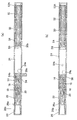
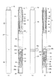
図1〜図6は、第1の実施形態に係る回転式繰出容器を用いた塗布具の説明図である。一部比較例も含んで記載している。図1は、第1の実施形態に係る回転式繰出容器を用いた塗布具の全体断面の説明図である。図2は、比較例に係る先軸と実施形態に係る先軸を対比する説明図である。図3は、実施形態に係る先軸の説明図である。図4は、比較例に係る軸本体と実施形態に係る軸本体に関して先方部の構造を対比する説明図である。図5は、ネジ棒の説明図である。図6はピストン体の説明図である。
Hereinafter, the applicator according to the present invention will be described based on the embodiments shown in the drawings.
1-6 is explanatory drawing of the applicator using the rotary delivery container which concerns on 1st Embodiment. Some comparative examples are also described. Drawing 1 is an explanatory view of the whole section of an applicator using the rotary delivery container concerning a 1st embodiment. FIG. 2 is an explanatory diagram comparing the front shaft according to the comparative example and the front shaft according to the embodiment. FIG. 3 is an explanatory diagram of a front shaft according to the embodiment. FIG. 4 is an explanatory diagram comparing the structure of the distal portion with respect to the shaft body according to the comparative example and the shaft body according to the embodiment. FIG. 5 is an explanatory diagram of a screw rod. FIG. 6 is an explanatory view of the piston body.

第1の実施形態に係る塗布具は、内部に流動体の貯留部(収容部)24を設けて、図1(a)に示すように、使用開始前はその流動体の吐出口を栓でシールした状態を維持する軸本体10と、塗布部を保持して使用開始前はストッパー(栓体ともいう)26cを介して軸本体10に仮に接合した仮接合の状態を維持し、一方、図1(b)に示すように、使用開始時にストッパー26cが外れることによって、そのストッパー26cの長さ分、軸方向に移動して軸本体10に直に接合する本接合の状態になる先軸20と、該先軸20の内部に配設されて先軸20が軸本体10に本接合する際の移動により上記軸本体10のシールボール(栓)24bに当接して、その栓抜きを行なうことにより、貯留部24から穂首(塗布部)22への流動体の供給を可能とする継手14、パイプ継手16、パイプ18等の流動体導通管とを備えてなる流動体の塗布具に係るものである。   The applicator according to the first embodiment is provided with a fluid reservoir (container) 24 inside, and as shown in FIG. 1 (a), the outlet of the fluid is plugged before use. The shaft main body 10 that maintains the sealed state and the temporarily bonded state that is temporarily bonded to the shaft main body 10 via the stopper (also referred to as a plug body) 26c before the start of use while holding the application portion are maintained. As shown in FIG. 1 (b), when the stopper 26c is removed at the start of use, the spindle 20 moves in the axial direction by the length of the stopper 26c and enters the state of the main joining directly joined to the shaft body 10. And a seal ball (plug) 24b of the shaft main body 10 that is disposed inside the front shaft 20 and moved when the front shaft 20 is finally joined to the shaft main body 10 to remove the bottle. The fluid from the storage unit 24 to the neck (application unit) 22 Joint 14 which allows the sheet, pipe fittings 16, but according to the applicator of the fluid comprising a fluid conduit, such as pipe 18.

第1の実施形態に係る塗布具は、回転式の繰出容器であり、図1に示すように、軸本体10後端部に配設された天冠12Aを軸本体10に対して周方向に相対回転させることにより貯留部24内の流動体内容物を繰り出すことが可能な容器である。   The applicator according to the first embodiment is a rotary feeding container. As shown in FIG. 1, the crown 12 </ b> A disposed at the rear end of the shaft body 10 is arranged in the circumferential direction with respect to the shaft body 10. It is a container which can draw out the fluid contents in the storage part 24 by rotating relatively.

上記塗布具は、軸本体10の後端に回転可能に嵌合された天冠12Aと、使用者による天冠12Aの回転の力をネジ棒30に伝える駆動筒52と、軸本体10に固定してネジ棒30が螺合するネジ体54と、先端にピストン体50が回転可能に係合したネジ棒30と、軸本体10の貯留部24内を摺動するピストン体50とを有する。前記駆動筒52を介して天冠12Aの回転をネジ棒30に伝え、該ネジ棒30の回転によってナット状のネジ体54の雌ネジを介して該ネジ棒30及びピストン体50が前進して貯留部24内から前記内容物を繰出す構造になっている。   The applicator is fixed to the shaft main body 10, a crown 12 </ b> A rotatably fitted to the rear end of the shaft main body 10, a drive cylinder 52 that transmits the rotational force of the crown 12 </ b> A by the user to the screw rod 30, and the shaft main body 10. Then, the screw body 54 is engaged with the threaded rod 30, the threaded rod 30 is rotatably engaged with the piston body 50 at the tip, and the piston body 50 is slid within the storage portion 24 of the shaft body 10. The rotation of the crown 12A is transmitted to the screw rod 30 through the drive cylinder 52, and the screw rod 30 and the piston body 50 are advanced by the rotation of the screw rod 30 through the female screw of the nut-like screw body 54. The contents are fed out from the storage unit 24.

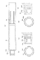
軸本体10は、図4に示すように、前端部10aが縮径されているが、内周面の後端部では凹凸段状の嵌合部10bが形成され、中央部のやや後方よりには、リブ10cが内方に突出して軸方向に延在して形成されている。軸本体10にネジ体54を装着するときには、軸本体10の開口した後端部から前記ネジ体54を前方向きに挿入し、前記リブ10cにネジ体54外周の前記溝部に装着しながら前進させて嵌め込んで行く。   As shown in FIG. 4, the shaft body 10 has a front end portion 10 a with a reduced diameter, but a concave and convex stepped fitting portion 10 b is formed at the rear end portion of the inner peripheral surface, and slightly behind the center portion. The rib 10c projects inward and extends in the axial direction. When the screw body 54 is attached to the shaft body 10, the screw body 54 is inserted forward from the open rear end of the shaft body 10, and is advanced while being attached to the groove portion on the outer periphery of the screw body 54 on the rib 10c. Go in.

天冠12Aは、図1に示すように、後端に蓋が嵌入することによって閉じられた筒状を呈する操作部が軸筒10後端部に回動可能に嵌め込まれ(嵌合部10b内に嵌着され)かつ露出しているものである。駆動筒52が天冠12A内に嵌入して回転方向に固定されており、この、駆動筒52内に回転方向固定かつ軸方向への相対移動可能にネジ体54が装着されている。   As shown in FIG. 1, the crown can 12 </ b> A has a cylindrical operation portion that is closed by fitting a lid at the rear end thereof, and is rotatably fitted to the rear end portion of the shaft tube 10 (inside the fitting portion 10 b). And is exposed). A drive cylinder 52 is fitted into the crown 12A and fixed in the rotational direction, and a screw body 54 is mounted in the drive cylinder 52 so as to be fixed in the rotational direction and relatively movable in the axial direction.

前記回転式繰出容器において、軸本体10前端部10aには、継手14、パイプ継手16、パイプ18、先軸20、穂首22が取り付けられる。軸本体10の貯留部24には、内容物の流動体(実施形態では、流動性化粧料等塗布液)が収容され、その貯留部24から繰出された流動体はパイプ18を通り穂首22先端に吐出されて、穂首22によって塗付可能になる。また、使用後にキャップ26を穂首22及び先軸20を覆うように先軸20に装着(嵌着)できるよう形成されている。   In the rotary feed container, a joint 14, a pipe joint 16, a pipe 18, a tip shaft 20, and a head 22 are attached to the front end 10 a of the shaft body 10. The storage part 24 of the shaft body 10 contains a fluid of contents (in the embodiment, a coating liquid such as fluid cosmetics), and the fluid fed from the storage part 24 passes through the pipe 18 and the neck 22. It is discharged to the tip and can be applied by the neck 22. Further, the cap 26 is formed so that it can be attached (fitted) to the front shaft 20 so as to cover the head 22 and the front shaft 20 after use.

なお、図1において符号24aは貯留部24内の内容物を往復動によって攪拌する攪拌ボール、24bはシールボールである。
また、26aはキャップ26内のインナーキャップ、26bはインナーキャップ後方付勢用のスプリングである。
また、符号26cは、未使用時における内容物のパイプ18から穂首22に向かう塗布液の流通路を閉鎖する位置に継手14、パイプ継手16、パイプ18、先軸20、穂首22を位置させるため、前記先軸20後端と軸本体10前端部10aの段状箇所前面との間にリング状部が装着されたストッパーである。このストッパー26cは、リング状部の一部が切り離され、その切り離された箇所の反対側に摘み片が一体形成され、摘み片を引くことによって、リング状部が切り離し箇所から拡径して前記先軸20後端と軸本体10の前端部10aとの間から取り外せるものになっている。
In FIG. 1, reference numeral 24a is an agitation ball for agitating the contents in the reservoir 24 by reciprocating motion, and 24b is a seal ball.
Reference numeral 26a denotes an inner cap in the cap 26, and 26b denotes a spring for biasing the inner cap rearward.
Reference numeral 26c indicates that the joint 14, the pipe joint 16, the pipe 18, the front shaft 20, and the head 22 are positioned at a position where the flow path of the coating liquid from the content pipe 18 to the head 22 is closed when not in use. For this purpose, the stopper is a ring-shaped portion mounted between the rear end of the front shaft 20 and the front surface of the stepped portion of the front end portion 10a of the shaft body 10. The stopper 26c has a part of the ring-shaped part cut off, and a knob piece is integrally formed on the opposite side of the cut-off part. It can be removed from between the rear end of the front shaft 20 and the front end portion 10 a of the shaft body 10.

図1(a)に示すように、未使用時ではシールボール24bが継手14の内径部に嵌入して密封しておりパイプ18内に内容物が流れ込まないようになっている。
一方、図1(b)に示すように使用時は、ユーザーがストッパー26cを軸本体10から引き抜き、先軸20を後端側に押し込むことにより、パイプ継手16の後端細径部がシールボール24bに突き当たってシールボール24bが継手14の内径部から外されて前記貯留部24内に入り込み、当該貯留部24内の内容物の流動体が継手14、パイプ継手16の内径部からパイプ18内に流入して、流動体が穂首22にその内部から供給されて、対象部に塗布可能になる。
なお、本発明において継手を密封するのにシールボールの使用に限定されない。例えば、密封部材として薄膜を継手14に一体的に設けてシールボール24bの代わりにすることができる。
As shown in FIG. 1A, when not in use, the seal ball 24 b is fitted and sealed in the inner diameter portion of the joint 14 so that the contents do not flow into the pipe 18.
On the other hand, as shown in FIG. 1B, when used, the user pulls out the stopper 26c from the shaft body 10 and pushes the front shaft 20 to the rear end side, so that the rear end small diameter portion of the pipe joint 16 becomes the seal ball. The seal ball 24b is removed from the inner diameter portion of the joint 14 and abuts into the storage portion 24, and the fluid of the contents in the storage portion 24 enters the pipe 18 from the inner diameter portion of the joint 14 and the pipe joint 16. The fluid is supplied to the neck 22 from the inside and can be applied to the target portion.
Note that the present invention is not limited to the use of a seal ball for sealing the joint. For example, a thin film can be provided integrally with the joint 14 as a sealing member to replace the sealing ball 24b.

また、図1、図4に示すように、軸本体10は、軸方向に見て前端部10aが貯留部24形成箇所よりも段状に小径になっていて、前端部10a内に筒状の継手14及びパイプ継手16が先軸20後部で覆われた状態で嵌入している。その先軸20前部内でパイプ継手16先方に塗布部(塗布体)として、多数の繊維が束ねられた、または、連続気泡体からなる筆先状の穂首22が挟持されている。なお、塗布部はこの種の穂首以外の適宜の構成を採用できる。   As shown in FIGS. 1 and 4, the shaft body 10 has a front end portion 10 a having a smaller diameter than the storage portion 24 formation portion when viewed in the axial direction, and has a cylindrical shape in the front end portion 10 a. The joint 14 and the pipe joint 16 are fitted in a state covered with the rear portion of the front shaft 20. In the front part of the tip shaft 20, a tip 22 of a brush-tip shape in which a large number of fibers are bundled or formed of an open cell body is sandwiched as an application part (applying body) in front of the pipe joint 16. In addition, the application part can employ | adopt appropriate structures other than this kind of head.

前記継手14は先端がフランジ状に外周に拡径し後端が内周に小孔(シールボール24bの嵌入孔)を残して壁状になった概略筒状を呈して軸本体10の前端部10aに嵌入しており、その継手14の先方開口内に先方からパイプ継手16が挿入されこのパイプ継手16に、貯留部24内から穂首22に向けて液体誘導用のパイプ18が挿入・支持されている。そして穂首22、先軸20を覆って、前端部10aにキャップ26を嵌着するようになっている。   The joint 14 has a generally cylindrical shape with a flange-like tip that expands to the outer periphery and a rear end that has a small hole (an insertion hole for the seal ball 24b) on the inner periphery. 10a, a pipe joint 16 is inserted into the joint 14 from the front, and a pipe 18 for liquid induction is inserted and supported in the pipe joint 16 from the reservoir 24 toward the head 22 Has been. A cap 26 is fitted to the front end portion 10a so as to cover the head 22 and the front shaft 20.

図1、図5に示すように、ネジ棒30は、前記駆動筒52の内周の異形断面孔に合う断面形状で外周部に雄ネジ30aを形成した棒状長尺体である。その前端部には、フランジ状に径方向突出する嵌合部30bを形成しており、その嵌合部30bにピストン体50が嵌入している。   As shown in FIGS. 1 and 5, the screw rod 30 is a rod-like long body having a cross-sectional shape that fits the modified cross-sectional hole on the inner periphery of the drive cylinder 52 and having an external thread 30 a on the outer peripheral portion. The front end portion is formed with a fitting portion 30b that protrudes in the radial direction like a flange, and the piston body 50 is fitted into the fitting portion 30b.

このピストン体50は、図6に示すように、貯留部24内壁に摺接する本体50aと、本体50aから後方に延びる中空筒状部50bと、中空筒状部50b内の凹凸の嵌合部50cを備えている。このピストン体50の嵌合部50cは、ネジ棒30先端の嵌合部30bを前記ピストン体50の嵌合部50cに嵌合(嵌入)させて、相対回転可能に前後方向移動を規制しており、この状態でピストン体50は軸本体10の貯留部24内で進退動可能に配設される。   As shown in FIG. 6, the piston body 50 includes a main body 50a that is in sliding contact with the inner wall of the reservoir 24, a hollow cylindrical portion 50b that extends rearward from the main body 50a, and an uneven fitting portion 50c in the hollow cylindrical portion 50b. It has. The fitting portion 50c of the piston body 50 is configured to fit (insert) the fitting portion 30b at the tip of the screw rod 30 into the fitting portion 50c of the piston body 50, thereby restricting forward and backward movement so as to be relatively rotatable. In this state, the piston body 50 is disposed in the storage portion 24 of the shaft body 10 so as to be able to advance and retract.

図1、図5に示すように、前記天冠12Aの駆動筒52に小判型等の異形断面孔を設け、内周に雌ネジが形成されたネジ体54を軸本体10に固定し、前記駆動筒52の異形断面孔に合う断面形状で外周部に雄ネジ30aを形成したネジ棒30を前記ネジ体54のネジ部に螺合させ、かつ、前記駆動筒52の異形断面孔に通過させた状態で前記駆動筒52の回転によりネジ棒30を回転させる。この回転によってピストン体50が貯留部24内で前進して化粧料などの流動体の内容物を先軸20内の塗布体である穂首22に供給するようになっている。   As shown in FIGS. 1 and 5, the drive cylinder 52 of the crown 12 </ b> A is provided with a modified cross-sectional hole such as an oval type, and a screw body 54 having an internal thread formed on the inner periphery is fixed to the shaft body 10, A screw rod 30 having a cross-sectional shape that matches the modified cross-sectional hole of the drive cylinder 52 and has an external thread 30a formed on the outer periphery thereof is screwed into the threaded portion of the screw body 54 and passed through the modified cross-sectional hole of the drive cylinder 52. In this state, the screw rod 30 is rotated by the rotation of the drive cylinder 52. By this rotation, the piston body 50 moves forward in the storage portion 24 and supplies the contents of the fluid such as cosmetics to the neck 22 that is the application body in the front shaft 20.

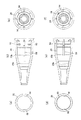
ここで、前記先軸20は図2(d)〜(f)、図3に示すように、後部よりも先部が先細になった概略コーン状を呈し、内周には、前記軸本体と仮接合するリブ56が略全周に渡り形成されている。
前記リブ56の軸方向に沿う断面の形状が略台形である。リブ56の断面の形状は、角がエッジになった台形形状に限られず、角部を面取り加工したものや円弧形状としたものでもよい。
Here, as shown in FIGS. 2 (d) to 2 (f) and FIG. 3, the front shaft 20 has a generally cone shape with a tapered tip than the rear portion. Ribs 56 to be temporarily joined are formed over substantially the entire circumference.
The shape of the cross section along the axial direction of the rib 56 is a substantially trapezoid. The shape of the cross section of the rib 56 is not limited to a trapezoidal shape with corners being edges, but may be a shape obtained by chamfering a corner or an arc shape.

先軸20では、先方部内周が穂首22を収容する円筒内周形状に形成され、中央部内周に前記パイプ継手16嵌入用の係合段部20aが形成される。また、先軸20の外周面には、キャップ26を嵌着固定するための、環状の凹部が形成されている。   In the front shaft 20, the inner periphery of the tip portion is formed in a cylindrical inner periphery shape that accommodates the neck 22, and the engagement step portion 20 a for fitting the pipe joint 16 is formed in the inner periphery of the center portion. An annular recess for fitting and fixing the cap 26 is formed on the outer peripheral surface of the front shaft 20.

先軸20の後部内周に、上記リブ56の他、軸方向に沿った方向にガイド用の縦リブ58が内向きに突出形成されている。
軸本体10の前端部10a外周部に軸方向に溝10a1と周方向に嵌合用の凸部10a2が環状に形成されている。前記先軸20を軸本体10に嵌着すると、前記縦リブ58が前記溝10a1内に嵌り込んで、前記先軸20及び軸本体10の相対回転が規制され、かつ、前記リブ56が前記凸部10a2に嵌合して、本接合して確実に先軸20の抜け止めをするようになっている。
なお、先軸20のリブ56よりも後部は拡径して後方に延びて椀状を呈しており、その拡径した部分が前記軸本体10の前端部10aの段状箇所を覆い、また、その後方の椀状の内部に段状箇所に当接・支持する凸部が配列形成されている。
In addition to the ribs 56, guide ribs 58 are formed in the rear inner periphery of the front shaft 20 so as to project inward in the direction along the axial direction.
A groove 10a1 is formed in the axial direction on the outer periphery of the front end portion 10a of the shaft body 10, and a convex portion 10a2 for fitting in the circumferential direction is formed in an annular shape. When the front shaft 20 is fitted to the shaft main body 10, the vertical rib 58 is fitted into the groove 10a1, the relative rotation of the front shaft 20 and the shaft main body 10 is restricted, and the rib 56 is the convex. The front shaft 20 is surely prevented from coming off by being fitted into the portion 10a2 and finally joined.
The rear part of the front shaft 20 is larger in diameter than the rib 56 and extends rearward to form a bowl-like shape, and the enlarged part covers the stepped portion of the front end 10a of the shaft body 10, Protrusions that contact and support the stepped portion are arranged in an array on the rear side of the bowl.

上記リブ56の嵌合力(リブ56によって従来よりも向上する先軸20の軸本体10に対する耐引き抜き力、抜けにくさ)について、比較するため、図2(a)〜(c)に比較例の先軸を示す。この比較例の先軸は、その先軸20後部内周に不連続な突起60、60が内周に配列形成されているものである。突起60、60はその周方向の長さは、配列された突起60、60同士の間隔よりも周方向に短く形成されているアンダーカットである。   In order to compare the fitting force of the rib 56 (the pull-out resistance against the shaft main body 10 which is improved by the rib 56 compared to the conventional case, the difficulty of coming off), FIGS. 2 (a) to 2 (c) show comparative examples. Indicates the tip axis. The front shaft of this comparative example has discontinuous protrusions 60 and 60 arranged on the inner periphery of the rear portion of the front shaft 20. The protrusions 60 and 60 are undercuts whose circumferential length is shorter than the distance between the arranged protrusions 60 and 60 in the circumferential direction.

このように比較例に係る突起60のアンダーカットの嵌合に比較して、図2(d)〜(f)に示す実施形態のリブ56によれば、部材の着色による圧入・引き抜き力の差が小さく、クリック感が十分でありユーザーが圧入を途中でやめるようなシール不良が生じにくく、また、先軸成形時に先軸の後端開口から覗き易くしたがって目視確認がし易い。
なお、本発明に係るリブ56には、一部溝が形成されていて、完全全周に渡るリブでなくてもよい。その場合、周方向に沿う一部溝の長さは、リブ56の長さよりも短くかつ断面同形であることが好ましい。
Thus, compared with the undercut fitting of the protrusion 60 according to the comparative example, according to the rib 56 of the embodiment shown in FIGS. Is small, the click feeling is sufficient, and it is difficult for the user to cause a sealing failure that stops the press-fitting in the middle, and it is easy to look through the opening at the rear end of the front shaft at the time of forming the front shaft.
The rib 56 according to the present invention may have a partial groove and may not be a rib that extends over the entire circumference. In that case, it is preferable that the length of the partial groove along the circumferential direction is shorter than the length of the rib 56 and has the same cross-sectional shape.

また、図4(d)、(e)に記載のように、前記先軸20と仮接合する軸本体10の前端部10a表面に突起部62を形成したものである。この突起部62は、球側面形状を呈しており、先軸20嵌合時に先軸20内面のリブ56を乗り越えてかつ先軸20内面のリブ56引っ掛かって無理に滑ることが無いので先軸20を前記軸本体10の前端10aに嵌合し易くかつ、リブ56に溝を切る必要が無く、溝がないことからリブ56自体の嵌合力が溝る場合に比べて高くなる。 Further, as shown in FIGS. 4D and 4E, a protrusion 62 is formed on the surface of the front end portion 10a of the shaft body 10 that is temporarily joined to the tip shaft 20. The protrusion 62 has the shape of a spherical side surface shape, so that there is no glide force caught overcame front barrel 20 inner surface of the rib 56 at the time of front barrel 20 fitted and the front barrel 20 the inner surface of the ribs 56, previously easily fitted to the shaft 20 to the front end portion 10a of the shaft body 10, and there is no need to cut a groove in the rib 56, higher than in the case fitting force of the ribs 56 themselves because there is no groove Ru Yes groove Become.

図7〜図16は、第2の実施形態に係るノック式繰出容器を用いた塗布具の説明図である。なお、図中、第1の実施形態と同様の箇所には、同一の符号を付している。
図7は、第2の実施形態に係るノック式繰出容器を用い説明図、図8は、図7に示すノック式繰出容器における天冠非押圧状態のノック機構部の断面拡大図を示す。図9は、図7のノック式繰出容器の天冠押圧状態のノック機構部の断面拡大図を示す。図10(a)〜(f)は、上記ノック式繰出容器のノック機構部の作動説明図である。
FIGS. 7-16 is explanatory drawing of the applicator using the knock type delivery container which concerns on 2nd Embodiment. In addition, in the figure, the same code | symbol is attached | subjected to the location similar to 1st Embodiment.
FIG. 7 is an explanatory view using the knock-type feeding container according to the second embodiment, and FIG. 8 is an enlarged cross-sectional view of the knock mechanism portion of the knock-type feeding container shown in FIG. FIG. 9 is an enlarged cross-sectional view of the knock mechanism portion of the knock-type feeding container of FIG. 10 (a) to 10 (f) are operation explanatory views of the knock mechanism portion of the knock-type feeding container.

図11(a)〜(e)は回転体の説明図、図12(a)〜(h)は天冠の説明図であって、(a)は天冠の前方斜視図、(b)は側面図、(c)は後方斜視図、(d)は前方視図、(e)は(b)と別の側面視図、(f)は後方視図、(g)は(a)と別の前方斜視図、(h)は縦断面図である。図13(a)〜(d)はネジ体の説明図である。図14(a)、(b)は、軸本体の斜視図、縦断面図である。図15(a)〜(g)はカム体の説明図である。図16は天冠とカム体との噛み合わせ状態を示す図である。   11A to 11E are explanatory views of a rotating body, FIGS. 12A to 12H are explanatory views of a crown, and FIG. 11A is a front perspective view of the crown, and FIG. (C) is a rear perspective view, (d) is a front view, (e) is a side view different from (b), (f) is a rear view, and (g) is different from (a). (H) is a longitudinal cross-sectional view. FIGS. 13A to 13D are explanatory views of the screw body. 14A and 14B are a perspective view and a longitudinal sectional view of the shaft body. FIGS. 15A to 15G are explanatory views of the cam body. FIG. 16 is a view showing a state in which the crown and the cam body are engaged with each other.

実施形態に係るノック式繰出容器は、図7に示すように、軸本体10後端部に配設された天冠12を軸方向前方に押圧することにより貯留部24内の内容物を繰り出すことが可能な容器であって、使用者のノック操作による天冠12の押圧の力を回転の力に変換するノック機構部Aと、軸本体10に固定したネジ体28と、ネジ体28に螺合させたネジ棒30とを有し、そのノック機構部Aが変換した回転の力でネジ棒30を回転させることによってネジ体28を介して該ネジ棒30を前進させて前記内容物を繰出す構造を有する。   As shown in FIG. 7, the knock-type feeding container according to the embodiment feeds the contents in the storage unit 24 by pressing the crown 12 disposed at the rear end of the shaft body 10 forward in the axial direction. A knock mechanism A for converting the pressing force of the crown 12 by a user's knocking operation into a rotational force, a screw body 28 fixed to the shaft body 10, and a screw on the screw body 28. The screw rod 30 is rotated by the rotational force converted by the knock mechanism A, and the screw rod 30 is advanced through the screw body 28 to repeat the contents. It has a structure to take out.

前記ノック式繰出容器において、軸本体10の前端部10aには、継手14、パイプ継手16、パイプ18、先軸20、穂首22が取り付けられ、軸本体10内の内容物(実施形態では、流動性化粧料等流動体)貯留部24から繰出された内容物はパイプ18を通り穂首22先端に吐出される。また、使用後にキャップ26を装着できるよう形成されている。なお、図7中24aは貯留部24内の内容物を往復動によって攪拌する攪拌ボール、26aはインナーキャップ、26bはインナーキャップ後方付勢用のスプリング、26cは未使用時における内容物のパイプ18以降への流通を閉鎖するストッパーである。パイプ18後端部には、未使用時ではシールボール24bが継手14の内径部に密着してパイプ18内に内容物が流れ込まないようになっており、一方、使用時は、ストッパー26cを軸本体10から引き抜き、先軸20を後端側に押し込むことにより、シールボール24bが継手14の内径部から外され、内容物がパイプ18に流入し、塗布することができる。   In the knock type feeding container, a joint 14, a pipe joint 16, a pipe 18, a tip shaft 20, and a head 22 are attached to the front end portion 10a of the shaft body 10, and the contents in the shaft body 10 (in the embodiment, Fluids such as fluid cosmetics) The contents fed from the storage unit 24 pass through the pipe 18 and are discharged to the tip of the ear 22. Further, the cap 26 can be attached after use. In FIG. 7, reference numeral 24a denotes a stirring ball for stirring the contents in the storage unit 24 by reciprocating motion, 26a denotes an inner cap, 26b denotes a spring for biasing the inner cap, 26c denotes a pipe 18 for the contents when not in use. It is a stopper that closes the distribution to the following. When the pipe 18 is not used, the seal ball 24b is in close contact with the inner diameter of the joint 14 so that the contents do not flow into the pipe 18 when the pipe 18 is not used. By pulling out the main body 10 and pushing the front shaft 20 toward the rear end side, the seal ball 24b is removed from the inner diameter portion of the joint 14, and the contents can flow into the pipe 18 and be applied.

また、図7、図14に示すように、軸本体10は、軸方向に見て前端部10aが段状に小径になっていて、前端部10a内に筒状の継手14及びパイプ継手16が先軸20後部で覆われた状態で嵌入しており、その先軸20前部内でパイプ継手16先方に塗布体として多数の繊維が束ねられ、または、連続気泡体からなる筆先状の穂首22が挟持されている。なお、塗布体はこの種の穂首以外の適宜の構成を採用できる。   Further, as shown in FIGS. 7 and 14, the shaft body 10 has a front end portion 10a having a small diameter in a step shape when viewed in the axial direction, and a cylindrical joint 14 and a pipe joint 16 are provided in the front end portion 10a. It is inserted in a state covered with the rear part of the front shaft 20, and a large number of fibers are bundled as an application body at the front of the pipe joint 16 in the front part of the front shaft 20, or a brush-shaped head 22 made of an open cell body. Is pinched. The application body can adopt an appropriate configuration other than this type of neck.

前記継手14は先方が拡径した概略筒状を呈して軸本体10の前端部10aに嵌入しており、その継手14の先方開口内に先方からパイプ継手16が挿入されこのパイプ継手16に、貯留部24内から穂首22に向けて液体誘導用のパイプ18が挿入・支持されている。そして穂首22、先軸20を覆って、前端部10aにキャップ26を嵌着するようになっている。   The joint 14 has a substantially cylindrical shape with an enlarged diameter at the tip, and is fitted into the front end portion 10a of the shaft body 10, and a pipe joint 16 is inserted into the pipe 14 from the front into the forward opening of the joint 14. A liquid guiding pipe 18 is inserted and supported from the reservoir 24 toward the neck 22. A cap 26 is fitted to the front end portion 10a so as to cover the head 22 and the front shaft 20.

以下に、各部具体的構成を説明する。
〔押圧の力を回転の力に変換するノック機構部A〕
前記天冠12の押圧による力を回転の力に変換するノック機構部Aは、図7、図8に示すように、第1のカム面32及び第2のカム面34を有する回転体36と、第1の固定カム面38を有するネジ体28、第2の固定カム面40を有するカム体42とを主な構成要素とする。
The specific configuration of each part will be described below.
[Knock mechanism A that converts pressing force into rotational force]
As shown in FIGS. 7 and 8, the knock mechanism A that converts the force generated by pressing the crown 12 into a rotational force includes a rotating body 36 having a first cam surface 32 and a second cam surface 34. The screw body 28 having the first fixed cam surface 38 and the cam body 42 having the second fixed cam surface 40 are main components.

〔回転体36〕
回転体36は、図7、図11に示すように、天冠12が回転可能かつ軸方向移動を規制して配設され、前方向きの第1のカム面32及び後方向きの第2のカム面34が形成された円環状のものであって軸本体10に回転可能かつ軸方向移動可能に配設されている。
[Rotating body 36]
As shown in FIGS. 7 and 11, the rotating body 36 is disposed such that the crown 12 can rotate and the axial movement is restricted, and the first cam surface 32 facing forward and the second cam facing backward. The surface 34 is formed in an annular shape, and is disposed on the shaft body 10 so as to be rotatable and movable in the axial direction.

回転体36は、図11に示すように、全体が概略中空筒状の円環状のものであって、軸方向の前端部には、前面に前方に向かう凸部の段差が形成された段部33を有する第1のカム面32が形成され、内径部に小判型等の異形断面孔46が形成されている。また、回転体36の軸方向中央部の外周部に段状に拡径した環状部分の後方向き面に後方向きの第2のカム面34が形成されている。また、回転体36の後端部外周には、フランジ状の凹凸の嵌合部36aが形成される。
なお、第1のカム面32だけではなく、第2のカム面34に上記段部と同様の段差のある段部を設けることも可能である。
As shown in FIG. 11, the rotating body 36 has a generally hollow cylindrical annular shape, and has a step portion in which a convex step toward the front is formed on the front surface at the front end portion in the axial direction. A first cam surface 32 having 33 is formed, and an odd-shaped cross-sectional hole 46 such as an oval shape is formed in the inner diameter portion. A second cam surface 34 facing rearward is formed on the rearward facing surface of the annular portion whose diameter is increased stepwise on the outer peripheral portion of the axially central portion of the rotating body 36. In addition, a flange-like uneven fitting portion 36 a is formed on the outer periphery of the rear end portion of the rotating body 36.
It is possible to provide not only the first cam surface 32 but also the second cam surface 34 with a stepped portion having the same step as the stepped portion.

天冠12は図12に示すように、軸方向一端が閉ざされたほぼ筒型状容器状を呈し、後部内周部に凹凸段状の係止部12aが形成される。天冠12の前端開口から前記回転体36の後端部を押し込むと前記嵌合部36aが前記係止部12aに嵌入する。前記嵌合部36aと係止部12aの各寸法が、天冠12が回転体36に対して軸方向の移動を規制するように形成されている。また、天冠12の前方側端面から前方に向けて(軸方向に沿って)突出させた天冠突起部12bを形成している。天冠突起部12bの本数は図面では平行に2本形成しているが特に指定しない。   As shown in FIG. 12, the crown 12 has a substantially cylindrical container shape with one axial end closed, and an uneven stepped locking portion 12 a is formed on the inner periphery of the rear part. When the rear end portion of the rotating body 36 is pushed in from the front end opening of the top crown 12, the fitting portion 36a is fitted into the locking portion 12a. The dimensions of the fitting portion 36a and the locking portion 12a are formed so that the crown 12 restricts the movement of the rotating body 36 in the axial direction. Moreover, the crown-shaped projection part 12b protruded toward the front from the front side end surface of the crown 12 (along the axial direction) is formed. Although the number of crown projections 12b is two in parallel in the drawing, it is not particularly specified.

〔ネジ体28〕
前記ネジ体28は、図7、図13に示すように、前端部が段状に縮径し、後端部が段状に拡径した概略中空筒状体である。前端部は段状に縮径した筒状部28aであって、内径部に雌ネジが形成されたネジ部48を有し、そのネジ部48のある筒状部28aの後面には斜面途中から前方に向かって凹む段差のある段部39を設けた第1の固定カム面38が形成される。
[Screw body 28]
As shown in FIGS. 7 and 13, the screw body 28 is a substantially hollow cylindrical body having a front end portion reduced in a step shape and a rear end portion enlarged in a step shape. The front end portion is a cylindrical portion 28a having a stepped diameter, and has a screw portion 48 having a female screw formed on the inner diameter portion, and the rear surface of the cylindrical portion 28a with the screw portion 48 is in the middle of the slope. A first fixed cam surface 38 provided with a stepped portion 39 that is recessed forward is formed.

ネジ体28の後端部28bはフランジ状に拡径しており、天冠12を回転及び進退動自在に内挿する部分であり、その後端部28bの前方に隣接する部分には軸方向に沿うスリット28cが複数ネジ体28内外を連通して形成されると共に、外周部に凹凸形成された嵌合部28dが形成される。さらに前部外周部には、軸方向に沿う溝部28eが複数形成されている。なお、ネジ体28の前部内周部には、後述するバネ部材44を径方向で位置決めするリブ28fが内方に突出して軸方向に延在して形成されている。   The rear end portion 28b of the screw body 28 is enlarged in a flange shape, and is a portion for inserting the crown 12 so that it can be rotated and moved forward and backward. A portion adjacent to the front of the rear end portion 28b is axially provided. Along the slit 28c is formed so as to communicate with the inside and outside of the plurality of screw bodies 28, and a fitting portion 28d formed with irregularities on the outer peripheral portion is formed. Further, a plurality of groove portions 28e along the axial direction are formed in the front outer peripheral portion. A rib 28f for positioning a spring member 44, which will be described later, in the radial direction is formed in the front inner periphery of the screw body 28 so as to protrude inward and extend in the axial direction.

〔軸本体10〕
軸本体10は、図14に示すように、前端部10aが縮径されているが、内周面の後端部では凹凸段状の嵌合部10bが形成され、中央部のやや後方よりには、リブ10cが内方に突出して軸方向に延在して形成されている。軸本体10にネジ体28を装着するときには、軸本体10の開口した後端部から前記ネジ体28を前方向きに挿入し、前記リブ10cを前記溝部28eに装着しながら前進させて嵌め込んで行く。
[Shaft body 10]
As shown in FIG. 14, the shaft main body 10 has a front end portion 10 a with a reduced diameter, but a concave and convex stepped fitting portion 10 b is formed at the rear end portion of the inner peripheral surface, slightly behind the center portion. The rib 10c projects inward and extends in the axial direction. When attaching the screw body 28 to the shaft body 10, the screw body 28 is inserted forward from the open rear end of the shaft body 10, and the rib 10c is advanced and fitted into the groove 28e. go.

そして、嵌合部10bにネジ体28の嵌合部28dの凹凸を乗り越えさせて押圧嵌入させて、その際に、ネジ体28の後端部28bのフランジ状に拡径した部分を軸本体10の後端面に突き当てるまで進める。リブ10cが溝部28eに、嵌合部10bが嵌合部にそれぞれ緊密に装着するので、ネジ体28は軸本体10に対して回転方向及び軸方向に固定しているので装着関係になる。
なお、軸本体10のネジ体28の前方空間は内容物の貯留部24を構成する。
Then, the fitting portion 10b is pressed and fitted over the concavity and convexity of the fitting portion 28d of the screw body 28, and at this time, the diameter-expanded portion of the rear end portion 28b of the screw body 28 is the shaft main body 10. Proceed until it hits the rear edge. Since the rib 10c is tightly attached to the groove 28e and the fitting portion 10b is tightly attached to the fitting portion, the screw body 28 is fixed in the rotational direction and the axial direction with respect to the shaft main body 10, so that there is a mounting relationship.
The space in front of the screw body 28 of the shaft main body 10 constitutes a content storage section 24.

〔カム体42〕
前記カム体42は、図15に示すように、概略中空筒状で前端面に第2の固定カム面40が形成され、中央部から後部にかけての外周側面に突起部42aが軸方向に延設されている。また、カム体42の後端面側には突起部42aとは略垂直方向の位置(カム体42の軸中心とした回転方向の位置が突起部42aと90°の角度差を持った位置)にカム体溝42bが前方側に向けて切り込んで形成されている。前記カム体42において、カム体溝42bの突起部42aとの前記回転方向の位置については、突起部42aと接触する位置でなければ特に指定しない。
[Cam body 42]
As shown in FIG. 15, the cam body 42 has a substantially hollow cylindrical shape, a second fixed cam surface 40 is formed on the front end surface, and a protruding portion 42 a extends in the axial direction on the outer peripheral side surface from the center portion to the rear portion. Has been. Further, the rear end surface of the cam body 42 is at a position substantially perpendicular to the protrusion 42a (the position in the rotational direction about the axis of the cam body 42 has a 90 ° angle difference from the protrusion 42a). The cam body groove 42b is formed by cutting toward the front side. In the cam body 42, the position of the cam body groove 42b in the rotational direction with respect to the protrusion 42a is not specified unless it is a position in contact with the protrusion 42a.

このカム体42は、図7、図8に示すように、回転体36外周に移動可能に嵌めた状態でネジ体28内に挿入して、突起部42aをネジ体28のスリット28cに嵌入してネジ体28の後端部28b内に係止するように嵌める。これにより、カム体42はネジ体28に対して回転方向及び軸方向への移動できないように固定され、また、前記のようにネジ体28が軸本体10に対して固定されるので、カム体42は軸本体10に対しても回転方向及び軸方向に固定される。さらに、図16に示すようにカム体溝42bが天冠12の天冠突起部12bに遊嵌し、天冠12が(上記軸本体10に対して回転方向及び軸方向に固定された)カム体42に対して回らずかつ進退動可能な構造になっている(回り止め手段)。したがって、天冠12は、軸本体10に対して回らずかつ進退動可能な構造になっている。
なお、上記のカム体42の第2の固定カム面40に、第1の固定カム面38の段部39と同様の段部を設けてもよい。
また、天冠12の回り止め手段として天冠突起部12bをカム体42のカム体溝42b内に遊び嵌めして天冠12とカム体42の各々同士が回らないようにすることによって、天冠12と回転体36が一緒に回転してしまう現象を回避し、ノック時におけるネジ体28と回転体36とで生じるカム動作不良を防止することができる。なお、カム体42を介して天冠12を軸本体10に対して回り止めしていたが、その他、ネジ体28の後部との間や軸本体10との間に回り止め手段を形成することも本発明の範囲内である。
As shown in FIGS. 7 and 8, the cam body 42 is inserted into the screw body 28 while being movably fitted on the outer periphery of the rotating body 36, and the protrusion 42 a is inserted into the slit 28 c of the screw body 28. Then, the screw body 28 is fitted into the rear end portion 28b. As a result, the cam body 42 is fixed to the screw body 28 so as not to move in the rotational direction and the axial direction, and the screw body 28 is fixed to the shaft body 10 as described above. 42 is also fixed to the shaft body 10 in the rotational direction and the axial direction. Further, as shown in FIG. 16, the cam body groove 42b is loosely fitted into the crown projection 12b of the crown 12 so that the crown 12 is fixed to the shaft body 10 in the rotational direction and the axial direction. The structure does not rotate with respect to the body 42 and can move forward and backward (rotation prevention means). Therefore, the crown 12 has a structure that does not rotate with respect to the shaft body 10 and can move forward and backward.
Note that a step similar to the step 39 of the first fixed cam surface 38 may be provided on the second fixed cam surface 40 of the cam body 42 described above.
Further, the crown canopy 12b is play-fitted into the cam body groove 42b of the cam body 42 to prevent the crown crown 12 and the cam body 42 from rotating as a means for preventing the crown 12 from rotating. The phenomenon that the crown 12 and the rotating body 36 rotate together can be avoided, and the cam operation failure caused by the screw body 28 and the rotating body 36 at the time of knocking can be prevented. Although the crown 12 is prevented from rotating with respect to the shaft main body 10 via the cam body 42, a rotation preventing means is formed between the rear portion of the screw body 28 and the shaft main body 10. Are also within the scope of the present invention.

〔バネ部材44〕
図7、図8に示すように、ネジ体28内には、前記回転体36の前部外周の環状突出部分の第2のカム面34反対側面と、ネジ体28の第1の固定カム面38を取り囲んだ部分との間には、バネ部材44が配設されている。このバネ部材44は、天冠12への前記押圧が解除された状態において、前記回転体36における第2のカム面34を、前記第2の固定カム面40に当接させて噛み合わせ状態になるように回転体36を後方に付勢する機能を奏する。バネ部材44には、バレル加工処理によってバネ端面のバリを除去し滑らかにすることで、スムーズな繰出動作をすることができる。
[Spring member 44]
As shown in FIGS. 7 and 8, in the screw body 28, a side surface opposite to the second cam surface 34 of the annular projecting portion of the front outer periphery of the rotating body 36, and a first fixed cam surface of the screw body 28. A spring member 44 is disposed between the portion surrounding the portion 38. The spring member 44 is brought into a meshed state by bringing the second cam surface 34 of the rotating body 36 into contact with the second fixed cam surface 40 in a state where the pressure on the crown 12 is released. Thus, there is a function of urging the rotating body 36 backward. The spring member 44 can be smoothly fed out by removing burrs on the spring end surface and smoothing it by barrel processing.

〔ネジ棒30、ピストン体50〕
図5に示すように、ネジ棒30は、前記回転体36の異形断面孔46に合う断面形状で外周部に雄ネジ30aを形成した棒状長尺体である。その前端部には、フランジ状に径方向突出する嵌合部30bを形成している。前記ネジ棒30先端部には軸本体10と摺動可能で前記ネジ棒30と軸方向に一体的に動くピストン体50が嵌合される。
[Screw rod 30, piston body 50]
As shown in FIG. 5, the screw rod 30 is a rod-like long body having a cross-sectional shape that matches the deformed cross-sectional hole 46 of the rotating body 36 and a male screw 30 a formed on the outer peripheral portion. At the front end portion, a fitting portion 30b that protrudes in the radial direction like a flange is formed. A piston body 50 slidable with the shaft body 10 and moves integrally with the screw rod 30 in the axial direction is fitted to the tip of the screw rod 30.

このピストン体50は、図7、図6に示すように、貯留部24内壁に摺接する本体50aと、本体50aから後方に延びる中空筒状部50bと、中空筒状部50b内の凹凸の嵌合部50cを備えている。このピストン体50の嵌合部50cは、ネジ棒30先端の嵌合部30bを前記ピストン体50の嵌合部50cに嵌合させて、相対回転可能に前後方向移動を規制しており、この状態でピストン体50は軸本体10の貯留部24内で進退動可能に配設される。   As shown in FIGS. 7 and 6, the piston body 50 includes a main body 50 a slidably contacting the inner wall of the storage portion 24, a hollow cylindrical portion 50 b extending rearward from the main body 50 a, and uneven fitting in the hollow cylindrical portion 50 b. The joint part 50c is provided. The fitting portion 50c of the piston body 50 restricts the movement in the front-rear direction so as to be relatively rotatable by fitting the fitting portion 30b at the tip of the screw rod 30 to the fitting portion 50c of the piston body 50. In this state, the piston body 50 is disposed in the storage portion 24 of the shaft body 10 so as to be able to advance and retract.

図7に示すように、前記回転体36に小判型等の異形断面孔46を設け、雌ネジからなるネジ部48及び第1の固定カム面38を有するネジ体28を軸本体10に固定し、前記回転体36の異形断面孔46に合う断面形状で外周部に雄ネジ30aを形成したネジ棒30を前記ネジ体28のネジ部に螺合させ、かつ、前記回転体36の異形断面孔46に通過させた状態で前記回転体36の回転によりネジ棒30を回転させる。この回転によってピストン体50が貯留部24内で前進して化粧料などの液体内容物を先軸20内の塗布体である穂首22に供給するようになっている。   As shown in FIG. 7, the rotary body 36 is provided with an odd-shaped cross-sectional hole 46 such as an oval shape, and a screw body 28 having a screw portion 48 formed of an internal thread and a first fixed cam surface 38 is fixed to the shaft body 10. The screw rod 30 having a cross-sectional shape matching the modified cross-sectional hole 46 of the rotating body 36 and having an external thread 30a formed on the outer periphery thereof is screwed into the threaded portion of the screw body 28, and the modified cross-sectional hole of the rotating body 36 is formed. The threaded rod 30 is rotated by the rotation of the rotating body 36 in the state of passing through 46. By this rotation, the piston body 50 moves forward in the storage portion 24 and supplies liquid contents such as cosmetics to the neck 22 that is an application body in the front shaft 20.

第1の固定カム面38及び第2の固定カム面40は、前記第1のカム面32及び第2のカム面34にそれぞれ対峙しかつ軸本体10に軸方向及び回転方向に固定して配置されている。   The first fixed cam surface 38 and the second fixed cam surface 40 face the first cam surface 32 and the second cam surface 34, respectively, and are fixed to the shaft body 10 in the axial direction and the rotational direction. Has been.

各第1の固定カム面38及び第2の固定カム面40と、前記第1のカム面32及び第2のカム面34の詳細を図10によって説明する。図10においては、図示説明の都合上、前記第1のカム面32及び第2のカム面34を一歯のみを示しているが、実施形態では、図11のように複数歯を形成している。もちろん、対峙するカム面の一方の歯が隙間無く連続していれば他方の歯の数は一つでも複数でもよい。   Details of each of the first fixed cam surface 38 and the second fixed cam surface 40, and the first cam surface 32 and the second cam surface 34 will be described with reference to FIG. In FIG. 10, only one tooth is shown for the first cam surface 32 and the second cam surface 34 for convenience of illustration, but in the embodiment, a plurality of teeth are formed as shown in FIG. Yes. Of course, the number of the other teeth may be one or more as long as one tooth of the facing cam surface is continuous without a gap.

詳しくは、前記回転体36の第1のカム面32は回転体の所定回転方向(図10では正面視左方向)に対して前方(図10では正面視下方向)に傾く斜面に前方に凹状段差の段部33を有すると共に、前記ネジ体28の第1の固定カム面38は上記回転体36の所定回転方向に対して前方に傾く斜面38a1に前方に凸状段差の段部39を有する。前記回転体36の第1のカム面32及びネジ体28の第1の固定カム面38は、回転体36の所定回転方向に傾く斜面32a1に及び38a1を有した第1の歯32a及び38aを所定回転方向に同一ピッチで複数形成したものであり、前記第1のカム面32及び第1の固定カム面38が有している各第1の歯の中間部分に段部33及び39が設けられている。   Specifically, the first cam surface 32 of the rotator 36 is concave forward on a slope inclined forward (downward in front view in FIG. 10) with respect to a predetermined rotation direction of the rotator (leftward in front view in FIG. 10). The first fixed cam surface 38 of the screw body 28 has a stepped stepped portion 39 on the front side of a slope 38a1 inclined forward with respect to a predetermined rotation direction of the rotating body 36. . The first cam surface 32 of the rotating body 36 and the first fixed cam surface 38 of the screw body 28 have first teeth 32a and 38a having inclined surfaces 32a1 and 38a1 inclined in a predetermined rotation direction of the rotating body 36. A plurality of step portions 33 and 39 are provided in the intermediate portions of the respective first teeth of the first cam surface 32 and the first fixed cam surface 38, which are formed in the predetermined rotation direction at the same pitch. It has been.

また、前記回転体36の第2のカム面34及び前記カム体42の第2の固定カム面40は、回転体36の所定回転方向(図10では正面視左方向)に対して後方(図10では正面視上方向)に傾く斜面34a1及び40a1を有した第2の歯34a及び40aを所定回転方向に同一ピッチで複数形成したものである。   Further, the second cam surface 34 of the rotating body 36 and the second fixed cam surface 40 of the cam body 42 are rearward (see FIG. 10) with respect to a predetermined rotational direction of the rotating body 36 (left direction in front view in FIG. 10). In FIG. 10, a plurality of second teeth 34a and 40a having inclined surfaces 34a1 and 40a1 inclined in the front direction (in the front view) are formed at the same pitch in a predetermined rotation direction.

なお、実施形態では、第1のカム面32及び第1の固定カム面38と第2のカム面34及び第2の固定カム面40のピッチ同士も同じに形成している。対峙するカム面の歯の数が異なる場合は、第1のカム面32及び第1の固定カム面38の一方と第2のカム面34及び第2の固定カム面40の一方とが歯のピッチが同一であればよい。   In the embodiment, the pitches of the first cam surface 32 and the first fixed cam surface 38 and the second cam surface 34 and the second fixed cam surface 40 are also formed to be the same. When the number of teeth on the facing cam surface is different, one of the first cam surface 32 and the first fixed cam surface 38 and one of the second cam surface 34 and the second fixed cam surface 40 have teeth. It is sufficient if the pitch is the same.

使用者が天冠12をノック操作した際には、前記押圧の力によって、前記回転体36における第1のカム面32が前記第1の固定カム面38に噛み合った状態で、第1のカム面32が前記第1の固定カム面38の歯38aの前方に傾く斜面38a1に沿って誘導されて行くことにより(図10(b)〜(c)参照)、前記回転体36が前方移動しかつ所定回転方に回転する。具体的には、第1のカム面32の段部33先端が前記第1の固定カム面38の斜面38a1に乗って滑って行く。   When the user knocks the crown 12, the first cam surface 32 is engaged with the first fixed cam surface 38 with the first cam surface 32 of the rotating body 36 by the pressing force. When the surface 32 is guided along the inclined surface 38a1 inclined forward of the teeth 38a of the first fixed cam surface 38 (see FIGS. 10B to 10C), the rotating body 36 moves forward. And it rotates in a predetermined direction. Specifically, the tip of the step 33 of the first cam surface 32 slides on the slope 38a1 of the first fixed cam surface 38.

このとき、図10(d)に示すように、第1のカム面32に設けられた段部33が第1の固定カム面38に設けられた段部39内に嵌り込む。すなわち、該第1のカム面32の歯32aの段部33が第1の固定カム面38aの段部39の凹所内に移動し、上記段部33がその段部39の凹所内に嵌り込み、第1のカム面32の歯32aの段部33の回転方向端面(壁面32a2)が第一の固定カム面38の反回転方向端の壁面38a2に当接することにより、打撃音すなわち、ノック音が発生し、繰出し容器を握っている使用者は手指にノック感覚を得ることができる。   At this time, as shown in FIG. 10 (d), the stepped portion 33 provided on the first cam surface 32 is fitted into the stepped portion 39 provided on the first fixed cam surface 38. That is, the stepped portion 33 of the teeth 32a of the first cam surface 32 moves into the recess of the stepped portion 39 of the first fixed cam surface 38a, and the stepped portion 33 fits into the recessed portion of the stepped portion 39. When the rotational end surface (wall surface 32a2) of the step portion 33 of the tooth 32a of the first cam surface 32 comes into contact with the wall surface 38a2 at the counter rotational end of the first fixed cam surface 38, a striking sound, that is, a knocking sound is generated. And the user holding the feeding container can get a sense of knocking on the fingers.

一方、前記押圧の解除により、前記回転体36における第2のカム面34が前記第2の固定カム面40に噛み合った状態で第2のカム面34が前記歯40aの後方に傾く斜面40a1に沿って誘導されて行くことにより(図10(e)〜(f)参照)、前記回転体36が後方移動しかつ所定回転方向に回転する。
上記動作のように各カムによる回転作動するように前記ノック機構部Aが構成され、回転体36の回転によって前記ネジ棒30を回転させるようにしたものである。
On the other hand, when the second cam surface 34 of the rotating body 36 is engaged with the second fixed cam surface 40 by the release of the pressing, the second cam surface 34 is inclined to the inclined surface 40a1 inclined to the rear of the teeth 40a. By being guided along (see FIGS. 10E to 10F), the rotating body 36 moves backward and rotates in a predetermined rotation direction.
The knock mechanism A is configured to rotate by each cam as in the above operation, and the screw rod 30 is rotated by the rotation of the rotating body 36.

ここで、前記回転体36の第1のカム面32が、前記第1の固定カム面38に噛み合わされた状態において(図10(d)参照)、前記第2の固定カム面40が、回転方向において第1の固定カム面38の一歯に対して位相がずれた関係に設定され、一方、前記回転体36側の第2のカム面34が、前記第2の固定カム面40に噛み合わされた状態において(図10(f)参照)、前記回転体36側の第1のカム面32と前記第1の固定カム面38が、回転方向においてカムの一歯に対して位相がずれた関係に設定されている。   Here, in a state where the first cam surface 32 of the rotating body 36 is engaged with the first fixed cam surface 38 (see FIG. 10D), the second fixed cam surface 40 rotates. The phase is set so as to be out of phase with respect to one tooth of the first fixed cam surface 38 in the direction, while the second cam surface 34 on the rotating body 36 side meshes with the second fixed cam surface 40. In this state (see FIG. 10F), the first cam surface 32 on the rotating body 36 side and the first fixed cam surface 38 are out of phase with respect to one tooth of the cam in the rotation direction. Set in a relationship.

また、前記押圧が解除された状態において、前記回転体36における第2のカム面34を、前記第2の固定カム面40に当接させて噛み合わせ状態になるように回転体36を後方に付勢するバネ部材44が具備されている。   Further, in a state where the pressure is released, the rotating body 36 is moved rearward so that the second cam surface 34 of the rotating body 36 is brought into contact with the second fixed cam surface 40 to be engaged. A biasing spring member 44 is provided.

つまり、上記ノック式繰出容器は、前記ネジ体28の中空内部には、円環状に形成され、前記第1の固定カム面38と噛み合う第1のカム面32を前部に形成しかつ第2のカム面34を後部に形成し、内径前部に異形断面孔46を設けた回転体36と、前記回転体36と前記ネジ体28との間に回転体36をネジ体28に対して後方に付勢するバネ部材44と、前記回転体36の第2のカム面34と噛み合う第2の固定カム面40を具備し前記ネジ体28の後部に固定されるカム体42とを配設し、前記回転体36を前記ネジ体28と前記カム体42で前後から挟み込み、前記バネ部材44により前記回転体36を前記カム体42に向けて付勢する構造にしている。   That is, the knock-type feeding container is formed in an annular shape inside the hollow portion of the screw body 28, and has a first cam surface 32 that meshes with the first fixed cam surface 38 at the front portion and a second portion. The rotating body 36 is formed in the rear part, and the rotating body 36 is provided behind the screw body 28 between the rotating body 36 and the screw body 28. A spring member 44 that biases the cam body 42, and a cam body 42 that includes a second fixed cam surface 40 that meshes with the second cam surface 34 of the rotating body 36 and is fixed to the rear portion of the screw body 28. The rotating body 36 is sandwiched from the front and rear by the screw body 28 and the cam body 42, and the rotating body 36 is biased toward the cam body 42 by the spring member 44.

そして、外径部にネジを備えて断面が異形のネジ棒30が前記ネジ体28のネジ部48に螺合し、前記回転体36の異形断面孔46により前記ネジ棒30と前記回転体36は軸方向に移動可能かつ回転方向に係止され、前記ネジ棒30先端部には軸本体10と摺動可能で前記ネジ棒30と軸方向に一体的に動くピストン体50が嵌合される。   Then, the screw rod 30 having an outer diameter portion with a screw and having an irregular cross section is screwed into the screw portion 48 of the screw body 28, and the screw rod 30 and the rotary body 36 are formed by the irregular cross sectional hole 46 of the rotary body 36. Is movable in the axial direction and locked in the rotational direction, and a piston body 50 that is slidable with the shaft main body 10 and moves integrally with the screw rod 30 in the axial direction is fitted to the tip of the screw rod 30. .

さらに、前記回転体36後部には前記天冠12が回転可能かつ軸方向には係止された状態で配設されている。   Further, the crown 12 is disposed at the rear portion of the rotating body 36 in a state where the crown 12 is rotatable and locked in the axial direction.

図10に示すように、前記回転体36の第1のカム面32が、前記第1の固定カム面38に噛み合わされた状態において、前記回転体36側の第2のカム面34と前記第2の固定カム面40が、回転方向においてカムの一歯に対して位相がずれた関係に設定され、前記回転体36の第2のカム面34が、前記第2の固定カム面40に噛み合わされた状態において、前記回転体36側の第1のカム面32と前記第1固定カム面が、回転方向においてカムの一歯に対して位相がずれた関係に設定されている。   As shown in FIG. 10, in a state where the first cam surface 32 of the rotating body 36 is engaged with the first fixed cam surface 38, the second cam surface 34 on the rotating body 36 side and the first cam surface The two fixed cam surfaces 40 are set to have a phase shifted relationship with respect to one tooth of the cam in the rotation direction, and the second cam surface 34 of the rotating body 36 meshes with the second fixed cam surface 40. In this state, the first cam surface 32 on the rotating body 36 side and the first fixed cam surface are set to have a phase shifted with respect to one tooth of the cam in the rotation direction.

次に、上記した実施形態の作動を説明する。   Next, the operation of the above-described embodiment will be described.

上記のノック式繰出容器において、回転体36の第1のカム面32及び第2のカム面34、ネジ体28の第1の固定カム面38、カム体42の第2の固定カム面40の相互動作の概略を図10(a)〜(f)に示す。   In the knock type feeding container, the first cam surface 32 and the second cam surface 34 of the rotating body 36, the first fixed cam surface 38 of the screw body 28, and the second fixed cam surface 40 of the cam body 42. The outline of the mutual operation is shown in FIGS.

図7、図8に示す天冠12をノック(押圧)しない初期状態では、図10(a)に示すように、回転体36はバネ部材44によりカム体42側に押し付けられ、回転体36の第2のカム面34とカム体42の第2の固定カム面40は噛み合った状態になっている。この状態の時、回転体36の第2のカム面34は、第1のカム面32と頂点が軸方向に対し平行して同一直線状にあり、ネジ体28の第1の固定カム面38とは位相がずれた状態である。   In an initial state where the crown 12 shown in FIGS. 7 and 8 is not knocked (pressed), the rotating body 36 is pressed against the cam body 42 by the spring member 44 as shown in FIG. The second cam surface 34 and the second fixed cam surface 40 of the cam body 42 are in mesh with each other. In this state, the second cam surface 34 of the rotating body 36 is collinear with the first cam surface 32 in parallel to the axial direction, and the first fixed cam surface 38 of the screw body 28. Is a state in which the phase is shifted.

次に、図9に示すように、天冠12を軸線方向に押圧してノックを開始する。   Next, as shown in FIG. 9, the crown 12 is pressed in the axial direction to start knocking.

ノックを開始すると、図10(a)から(b)に変化する。つまり、天冠12と回転体36はバネ部材44を圧縮させながら一体的に前方へ移動を開始し、回転体36の第2のカム面34はカム体42の第2の固定カム面40から離れて行く。   When knocking is started, the state changes from FIG. That is, the crown 12 and the rotating body 36 start moving forward integrally while compressing the spring member 44, and the second cam surface 34 of the rotating body 36 moves from the second fixed cam surface 40 of the cam body 42. Go away.

さらにノックを続けると図10(b)に示すように、回転体36の第1のカム面32は、ネジ体28の第1の固定カム面38に位相がずれた状態で当接する。   When knocking continues, as shown in FIG. 10B, the first cam surface 32 of the rotating body 36 comes into contact with the first fixed cam surface 38 of the screw body 28 in a state of being out of phase.

図10(c)に示すように、この当接した状態からさらに押圧すると、ネジ体28の第1の固定カム面38の歯38aの斜面38a1を、回転体36の第1のカム面32の歯32aの斜面32a1が滑って行き、当該歯32aの壁部32a2が第1の固定カム面38の歯38aの壁部38a2と当接する位置まで(図10(d)に示す)、回転体36が所定方向に回転しながら前方へ移動する。この時、回転体36は天冠12に対して回転可能に取り付けられているため天冠12自体は回転しない。   As shown in FIG. 10 (c), when further pressed from this abutted state, the inclined surface 38 a 1 of the tooth 38 a of the first fixed cam surface 38 of the screw body 28 is moved to the first cam surface 32 of the rotating body 36. The inclined surface 32a1 of the tooth 32a slides, and the rotating body 36 reaches a position where the wall portion 32a2 of the tooth 32a comes into contact with the wall portion 38a2 of the tooth 38a of the first fixed cam surface 38 (shown in FIG. 10 (d)). Moves forward while rotating in a predetermined direction. At this time, since the rotating body 36 is rotatably attached to the crown 12, the crown 12 itself does not rotate.

このノック時の回転体36の回転に伴い、回転体36先端に配された異形断面孔46を貫通して、回転体36と回転方向に規制され軸線方向に移動自由に設けたネジ棒30が回転体36と一体的に回転する。ネジ棒30はネジ体28ネジ部48と螺合していることによりピストン体50と共に前進し貯留部24の内容物を繰出す。   Along with the rotation of the rotator 36 at the time of knocking, a screw rod 30 that passes through the deformed cross-sectional hole 46 disposed at the tip of the rotator 36 and that is regulated in the rotation direction and freely movable in the axial direction is provided. It rotates integrally with the rotating body 36. Since the screw rod 30 is screwed with the screw body 28 and the screw portion 48, the screw rod 30 moves forward together with the piston body 50 and feeds the contents of the storage portion 24.

この状態からノックを解除する。   The knock is released from this state.

ネジ体28内部に配設されたバネ部材44が回転体36を押上げることでノックを解除して行くが、この時、回転体36の第2のカム面34はカム体42の第2の固定カム40の歯40aの配列ピッチは位相がずれた状態であるので、該第2のカム面34は所定回転方向に回転及び後方へ移動を開始する。   The spring member 44 disposed inside the screw body 28 pushes up the rotating body 36 to release the knocking. At this time, the second cam surface 34 of the rotating body 36 has a second cam surface 42 of the cam body 42. Since the arrangement pitch of the teeth 40a of the fixed cam 40 is out of phase, the second cam surface 34 starts to rotate and move backward in a predetermined rotational direction.

さらにノック解除を続けると図10(e)に示すように、回転体36の第2のカム面34がカム体42の第2の固定カム面40に当接し、図10(f)に示すように、バネ部材44の押上げ力で回転体36の第2のカム面34の歯34a斜面34a1が、カム体42の第2の固定カム面40の歯40a斜面40a1を滑って行くことにより、第2のカム面34の歯34aの壁部34a2がその第2の固定カム面40の歯40aの壁部40a2と当接する位置まで回転しながら後退する。この回転時も上記の通りネジ棒30を回転させピストン体50と共に前進し、内容物を繰出す。   When the knock release is further continued, as shown in FIG. 10 (e), the second cam surface 34 of the rotating body 36 comes into contact with the second fixed cam surface 40 of the cam body 42, and as shown in FIG. 10 (f). Further, the tooth 34a slope 34a1 of the second cam surface 34 of the rotating body 36 slides on the tooth 40a slope 40a1 of the second fixed cam surface 40 of the cam body 42 by the pushing force of the spring member 44. The wall portion 34a2 of the tooth 34a of the second cam surface 34 retreats while rotating to a position where the wall portion 40a2 of the tooth 40a of the second fixed cam surface 40 abuts. Also during this rotation, the screw rod 30 is rotated as described above to move forward with the piston body 50, and the contents are fed out.

上記のノック動作を繰り返すことにより、第1のカム面と第1の固定カム面が噛み合うときにはノックオンが発生し、軸線方向のノック動作及び解除動作が回転の力に変換され、ネジ棒30を回転させ、ピストン体50を押し出すことで内容物を定量的に繰出すことが可能となる。   By repeating the above knocking operation, when the first cam surface and the first fixed cam surface are engaged with each other, knock-on occurs, the axial knocking operation and the releasing operation are converted into rotational force, and the screw rod 30 is rotated. Then, by pushing out the piston body 50, the contents can be fed out quantitatively.

また初期の回転は押圧力にその回転力の強さが依存されるため、ピストン体50の張り付きなどで初期回転に一定以上の力が必要となった場合にも対応し易い。   In addition, since the initial rotation depends on the strength of the rotational force depending on the pressing force, it is easy to deal with a case where a certain force or more is required for the initial rotation due to sticking of the piston body 50 or the like.

なお、本発明のノック式繰出容器は、上記した実施の形態に限定されるものではなく、本発明の要旨を逸脱しない範囲内において種々変更を加え得ることはもちろんである。   Note that the knock-type feeding container of the present invention is not limited to the above-described embodiment, and various modifications can be made without departing from the scope of the present invention.

実施形態では、各部品を樹脂成型品とすることが好適であり、軸本体がPP、回転体がPOM、カム体がABS、ネジ体がABS、天冠がPCを材料とすることが好ましい。   In the embodiment, each component is preferably a resin molded product, and it is preferable that the shaft body is made of PP, the rotating body is POM, the cam body is ABS, the screw body is ABS, and the crown is made of PC.

また、実施形態では、回転体36の第1のカム面32及びネジ体28の第1の固定カム面38と、回転体の第2のカム面34及びカム体42の第2の固定カム面40の歯は何れも双方とも同一ピッチで複数の歯を形成していたが本発明はこのような構成に限定されない。第1のカム面及び第1の固定カム面の一方を、回転体の所定回転方向に対して前方に傾く斜面を有した第1の歯を所定回転方向に同一ピッチで複数形成し、第2のカム面及び第2の固定カム面の一方は、回転体の所定回転方向に対して後方に傾く斜面を有した第2の歯を所定回転方向に同一ピッチで複数形成したものとして、つまり、対峙するカム面の何れか一方を複数歯で形成し、他方を単数または複数の歯を有するカムとすることも本発明の範囲内である。   In the embodiment, the first cam surface 32 of the rotating body 36 and the first fixed cam surface 38 of the screw body 28, and the second cam surface 34 of the rotating body and the second fixed cam surface of the cam body 42 are used. Both of the 40 teeth formed a plurality of teeth at the same pitch, but the present invention is not limited to such a configuration. One of the first cam surface and the first fixed cam surface is formed with a plurality of first teeth having a slope inclined forward with respect to a predetermined rotation direction of the rotating body at the same pitch in the predetermined rotation direction. One of the cam surface and the second fixed cam surface is formed by forming a plurality of second teeth having inclined surfaces inclined rearward with respect to a predetermined rotation direction of the rotating body at the same pitch in the predetermined rotation direction. It is also within the scope of the present invention that either one of the opposing cam surfaces is formed with a plurality of teeth and the other is a cam having one or more teeth.

10 軸本体
10a 軸本体の前端部
10b 嵌合部
10c リブ
12A 天冠(第1の実施形態)
12 天冠(第2の実施形態)
12a 係止部
12b 天冠突起部
14 継手
16 パイプ継手
18 パイプ
20 先軸
22 穂首
24 貯留部
24a 攪拌ボール
24b シールボール
26 キャップ
26a インナーキャップ
26b インナーキャップ後方付勢用スプリング
26c ストッパー
28 ネジ体(第2の実施形態)
28a ネジ体の前端の筒状部
28b ネジ体の後端部
28c スリット
28d 嵌合部
28e 溝部
28f リブ
30 ネジ棒
30a 雄ネジ
30b 嵌合部
32 第1のカム面
32a 第1のカム面の歯
32a1 第1のカム面の歯の斜面
32a2 歯の壁部
33 段部
34 第2のカム面
34a 第2のカム面の歯
34a1 第2のカム面の歯の斜面
34a2 第2のカム面の歯の壁部
36 回転体
36a 嵌合部
38 第1の固定カム面
38a 第1の固定カム面の歯
38a1 第1の固定カム面の歯の斜面
38a2 第1の固定カム面の歯の壁部
39 段部
40 第2の固定カム面
40a 第2の固定カム面の歯
40a1 第2の固定カム面の歯の斜面
40a2 第2の固定カム面の歯の壁部
42 カム体
42a 突起部
42b カム体溝
44 バネ部材
46 異形断面孔
48 ネジ体のネジ部
50 ピストン体
50a 本体
50b 筒状部
50c 嵌合部
52 駆動筒
54 ネジ体(第1の実施形態)
56 リブ
58 縦リブ
60 突起
62 突起部
A 押圧の力を回転の力に変換するノック機構部
DESCRIPTION OF SYMBOLS 10 Shaft main body 10a Shaft main body front end part 10b Fitting part 10c Rib 12A Crown (1st Embodiment)
12 crown (second embodiment)
12a Locking portion 12b Crown crown portion 14 Joint 16 Pipe joint 18 Pipe 20 Lead shaft 22 Ear neck 24 Reservoir 24a Stirring ball 24b Seal ball 26 Cap 26a Inner cap 26b Inner cap rear urging spring 26c Stopper 28 Screw body ( Second embodiment)
28a Cylindrical portion 28b at the front end of the screw body Rear end portion 28c of the screw body Slit 28d Fitting portion 28e Groove portion 28f Rib 30 Screw rod 30a Male screw 30b Fitting portion 32 First cam surface 32a First cam surface teeth 32a1 Tooth slope of the first cam surface 32a2 Tooth wall portion 33 Step portion 34 Second cam surface 34a Second cam surface tooth 34a1 Second cam surface tooth slope 34a2 Second cam surface tooth Wall 36 of the rotating body 36a Fitting portion 38 First fixed cam surface 38a First fixed cam surface tooth 38a1 First fixed cam surface tooth slant 38a2 First fixed cam surface tooth wall 39 Step 40 Second fixed cam surface 40a Second fixed cam surface tooth 40a1 Second fixed cam surface tooth slant 40a2 Second fixed cam surface tooth wall 42 Cam body 42a Projection 42b Cam body Groove 44 spring member 46 irregular cross-section hole 48 Threaded portion 50 piston body 50a body 50b cylindrical portion 50c fitting portion 52 drive sleeve 54 threaded body of the body (first embodiment)
56 Ribs 58 Vertical ribs 60 Protrusions 62 Protrusions A Knock mechanism for converting pressing force into rotational force

Claims (1)

内部に流動体の貯留部を設けて、使用開始前はその流動体の吐出口を栓でシールした状態を維持する軸本体と、塗布部を保持して使用開始前はストッパーを介して軸本体に直に接合しない仮接合の状態を維持し、一方、使用開始時にストッパーが外れることによってそのストッパーの長さ分、軸方向に移動して軸本体に直に接合する本接合の状態になる先軸と、該先軸の内部に配設されて先軸が軸本体に本接合する際の移動により上記軸本体の栓に当接した後、その栓抜きを行なうことにより、貯留部から塗布部への流動体の供給を可能とする流動体導通管とを備えてなる流動体の塗布具において、
軸本体の前端部の外周面には、軸方向の溝と、周方向に嵌合用である環状の凸部と、前記先軸と仮接合する突起部が形成され、
前記先軸の外周面にはキャップを嵌着固定するための環状の凹部が形成され、前記先軸の内周面には、前記軸本体の環状の凸部に係止して本接合するものであって、軸方向に沿う断面の形状が略台形であるリブが略全周に渡り内向きに突出形成されており、
前記リブの一部に縦方向の縦リブが形成されていて、
前記先軸が軸本体の前端部に仮接合する際は、前記縦リブが軸方向の溝内に嵌り込み、
一方、前記ストッパーが外れて前記先軸が軸本体の前端部に対して仮接合の状態から本接合する際の移動時に、前記先軸内周面の前記リブが該凸部の後部に嵌合し、前記先軸及び前記軸本体の相対回転が規制されることで本接合することを特徴とする塗布具。
A shaft body that has a fluid reservoir inside and maintains the fluid discharge port sealed with a stopper before the start of use, and a shaft body that holds the applicator and uses a stopper before the start of use. The temporary joining state that is not directly joined to the shaft is maintained. On the other hand, when the stopper is removed at the start of use, it moves in the axial direction by the length of the stopper and enters the state of the main joining directly joined to the shaft body. After the shaft and the shaft disposed inside the shaft are brought into contact with the plug of the shaft main body by movement when the main shaft is joined to the shaft main body, the container is removed from the reservoir portion by removing the bottle. In a fluid applicator comprising a fluid conducting tube that enables the fluid to be supplied to
On the outer peripheral surface of the front end portion of the shaft body, there are formed an axial groove, an annular convex portion for fitting in the circumferential direction, and a projection portion that is temporarily joined to the front shaft,
An annular recess for fixing and fixing a cap is formed on the outer peripheral surface of the front shaft, and the inner peripheral surface of the front shaft is locked to the annular convex portion of the shaft main body and is finally joined. The rib having a substantially trapezoidal cross-sectional shape along the axial direction is formed to protrude inward over substantially the entire circumference,
A longitudinal longitudinal rib is formed on a part of the rib,
When the front shaft is temporarily joined to the front end portion of the shaft body, the vertical rib is fitted in the axial groove,
On the other hand, the rib on the inner peripheral surface of the front shaft is fitted to the rear portion of the convex portion when the stopper is removed and the front shaft moves during the main joining from the temporarily joined state to the front end of the shaft body. And the applicator characterized by carrying out this joining by the relative rotation of the said front shaft and the said shaft main body being controlled.
JP2011020527A 2011-02-02 2011-02-02 Applicator Active JP6045127B2 (en)

Priority Applications (1)

Application Number Priority Date Filing Date Title
JP2011020527A JP6045127B2 (en) 2011-02-02 2011-02-02 Applicator

Applications Claiming Priority (1)

Application Number Priority Date Filing Date Title
JP2011020527A JP6045127B2 (en) 2011-02-02 2011-02-02 Applicator

Publications (3)

Publication Number Publication Date
JP2012157611A JP2012157611A (en) 2012-08-23
JP2012157611A5 JP2012157611A5 (en) 2014-02-20
JP6045127B2 true JP6045127B2 (en) 2016-12-14

Family

ID=46838650

Family Applications (1)

Application Number Title Priority Date Filing Date
JP2011020527A Active JP6045127B2 (en) 2011-02-02 2011-02-02 Applicator

Country Status (1)

Country Link
JP (1) JP6045127B2 (en)

Families Citing this family (4)

* Cited by examiner, † Cited by third party
Publication number Priority date Publication date Assignee Title
KR20180095688A (en) 2015-12-25 2018-08-27 미쓰비시 엔피쯔 가부시키가이샤 Liquid cosmetic composition
JP6738643B2 (en) 2016-04-14 2020-08-12 三菱鉛筆株式会社 Applicator
KR101822031B1 (en) * 2016-12-23 2018-01-25 김동현 A hair brush for dyeing
US11766110B2 (en) 2019-03-15 2023-09-26 Mitsubishi Pencil Company, Limited Applicator

Family Cites Families (3)

* Cited by examiner, † Cited by third party
Publication number Priority date Publication date Assignee Title
JPH0725259Y2 (en) * 1989-10-19 1995-06-07 三菱鉛筆株式会社 Fluid applicator
JP4321909B2 (en) * 1999-04-30 2009-08-26 三菱鉛筆株式会社 Liquid applicator
EP1317891B1 (en) * 2001-12-05 2007-01-31 Kotobuki &amp; Co. Ltd. Knocking type liquid container

Also Published As

Publication number Publication date
JP2012157611A (en) 2012-08-23

Similar Documents

Publication Publication Date Title
JP5545632B2 (en) Liquid feed container
JP6045127B2 (en) Applicator
WO2009125868A1 (en) Knock type advancing container
JP5399839B2 (en) Knock-type feeding container
WO2014054433A1 (en) Cartridge-type cosmetic container
JP5452753B1 (en) Cartridge type cosmetic container
JP5234596B2 (en) Knock-type feeding container
JP5294789B2 (en) Knock-type feeding container
JP6424005B2 (en) Liquid feed container
JP5610775B2 (en) Liquid applicator
JP5545681B2 (en) Liquid feed container
JP5970323B2 (en) Cosmetic material supply container
JP7394199B2 (en) cosmetic applicator
JP2017113163A (en) Applicator
JP2009247427A (en) Rotary type dispensing container
JP5248262B2 (en) Feeding mechanism of knock-type feeding container
JP6318344B2 (en) Cartridge-type contents extrusion container
JP5798789B2 (en) Container with applicator
JP6244161B2 (en) Rotating pay-out writing instrument and method for manufacturing the same
JP6488734B2 (en) Member connection structure
JP5452688B1 (en) Cartridge type cosmetic container
WO2019202849A1 (en) Stick cosmetic delivery container
JP2008093239A (en) Cosmetic material applicator container
MX2013014412A (en) Writing implement, in particular a marker, having a reloadable supply unit.
JP2014226205A (en) Cartridge type cosmetic container

Legal Events

Date Code Title Description
A521 Request for written amendment filed

Free format text: JAPANESE INTERMEDIATE CODE: A523

Effective date: 20131226

A621 Written request for application examination

Free format text: JAPANESE INTERMEDIATE CODE: A621

Effective date: 20131226

A977 Report on retrieval

Free format text: JAPANESE INTERMEDIATE CODE: A971007

Effective date: 20141017

A131 Notification of reasons for refusal

Free format text: JAPANESE INTERMEDIATE CODE: A131

Effective date: 20141202

A521 Request for written amendment filed

Free format text: JAPANESE INTERMEDIATE CODE: A523

Effective date: 20150202

A131 Notification of reasons for refusal

Free format text: JAPANESE INTERMEDIATE CODE: A131

Effective date: 20150908

A521 Request for written amendment filed

Free format text: JAPANESE INTERMEDIATE CODE: A523

Effective date: 20151109

A131 Notification of reasons for refusal

Free format text: JAPANESE INTERMEDIATE CODE: A131

Effective date: 20160510

A521 Request for written amendment filed

Free format text: JAPANESE INTERMEDIATE CODE: A523

Effective date: 20160624

TRDD Decision of grant or rejection written
A01 Written decision to grant a patent or to grant a registration (utility model)

Free format text: JAPANESE INTERMEDIATE CODE: A01

Effective date: 20161115

A61 First payment of annual fees (during grant procedure)

Free format text: JAPANESE INTERMEDIATE CODE: A61

Effective date: 20161115

R150 Certificate of patent or registration of utility model

Ref document number: 6045127

Country of ref document: JP

Free format text: JAPANESE INTERMEDIATE CODE: R150

R250 Receipt of annual fees

Free format text: JAPANESE INTERMEDIATE CODE: R250

R250 Receipt of annual fees

Free format text: JAPANESE INTERMEDIATE CODE: R250