JP6044113B2 - Power supply control device, image processing device - Google Patents
Power supply control device, image processing device Download PDFInfo
- Publication number
- JP6044113B2 JP6044113B2 JP2012110754A JP2012110754A JP6044113B2 JP 6044113 B2 JP6044113 B2 JP 6044113B2 JP 2012110754 A JP2012110754 A JP 2012110754A JP 2012110754 A JP2012110754 A JP 2012110754A JP 6044113 B2 JP6044113 B2 JP 6044113B2
- Authority
- JP
- Japan
- Prior art keywords
- detection
- power supply
- processing apparatus
- unit
- moving body
- Prior art date
- Legal status (The legal status is an assumption and is not a legal conclusion. Google has not performed a legal analysis and makes no representation as to the accuracy of the status listed.)
- Active
Links
Images


Classifications
-
- H—ELECTRICITY
- H02—GENERATION; CONVERSION OR DISTRIBUTION OF ELECTRIC POWER
- H02J—CIRCUIT ARRANGEMENTS OR SYSTEMS FOR SUPPLYING OR DISTRIBUTING ELECTRIC POWER; SYSTEMS FOR STORING ELECTRIC ENERGY
- H02J9/00—Circuit arrangements for emergency or stand-by power supply, e.g. for emergency lighting
- H02J9/005—Circuit arrangements for emergency or stand-by power supply, e.g. for emergency lighting using a power saving mode
-
- G—PHYSICS
- G03—PHOTOGRAPHY; CINEMATOGRAPHY; ANALOGOUS TECHNIQUES USING WAVES OTHER THAN OPTICAL WAVES; ELECTROGRAPHY; HOLOGRAPHY
- G03G—ELECTROGRAPHY; ELECTROPHOTOGRAPHY; MAGNETOGRAPHY
- G03G15/00—Apparatus for electrographic processes using a charge pattern
- G03G15/50—Machine control of apparatus for electrographic processes using a charge pattern, e.g. regulating differents parts of the machine, multimode copiers, microprocessor control
- G03G15/5004—Power supply control, e.g. power-saving mode, automatic power turn-off
-
- G—PHYSICS
- G06—COMPUTING; CALCULATING OR COUNTING
- G06K—GRAPHICAL DATA READING; PRESENTATION OF DATA; RECORD CARRIERS; HANDLING RECORD CARRIERS
- G06K15/00—Arrangements for producing a permanent visual presentation of the output data, e.g. computer output printers
- G06K15/40—Details not directly involved in printing, e.g. machine management, management of the arrangement as a whole or of its constitutive parts
- G06K15/4055—Managing power consumption, e.g. standby mode
- G06K15/406—Wake-up procedures
-
- H—ELECTRICITY
- H04—ELECTRIC COMMUNICATION TECHNIQUE
- H04N—PICTORIAL COMMUNICATION, e.g. TELEVISION
- H04N1/00—Scanning, transmission or reproduction of documents or the like, e.g. facsimile transmission; Details thereof
- H04N1/00885—Power supply means, e.g. arrangements for the control of power supply to the apparatus or components thereof
- H04N1/00888—Control thereof
- H04N1/00891—Switching on or off, e.g. for saving power when not in use
-
- H—ELECTRICITY
- H04—ELECTRIC COMMUNICATION TECHNIQUE
- H04N—PICTORIAL COMMUNICATION, e.g. TELEVISION
- H04N2201/00—Indexing scheme relating to scanning, transmission or reproduction of documents or the like, and to details thereof
- H04N2201/0077—Types of the still picture apparatus
- H04N2201/0094—Multifunctional device, i.e. a device capable of all of reading, reproducing, copying, facsimile transception, file transception
Description
本発明は、電力供給制御装置、画像処理装置に関する。 The present invention relates to a power supply control device and an image processing device.
特許文献1には、人体検知センサを備えた機器を使用する人が機器の前方にいる場合であって、一定時間が経過しないと操作できないという不具合を解決するべく、人体検知センサにより機器の正面に人がいない状態からいる状態に変化したことを検知した信号が出力されたときに、操作部コントローラのみを省エネモードから通常モードへ復帰せしめ、さらに機器の正面に人がいる状態が一定時間継続したときに、エンジンコントローラをも通常モードへ復帰するように制御することが開示されている。 In Patent Document 1, in order to solve the problem that a person using a device equipped with a human body detection sensor is in front of the device and cannot operate until a certain time has elapsed, the human body detection sensor is used to solve the problem. When a signal is detected that indicates that there has been a change from a state where there is no person, only the operation unit controller is returned from the energy-saving mode to the normal mode, and the state where a person is in front of the device continues for a certain period of time. In such a case, it is disclosed that the engine controller is also controlled to return to the normal mode.
特許文献2には、省電力モード中に人体検知センサ(反射センサ)から検知信号を受けたときに、内部処理回路部への電力供給を開始することが記載されている。 Patent Document 2 describes that power supply to an internal processing circuit unit is started when a detection signal is received from a human body detection sensor (reflection sensor) during a power saving mode.
本発明は、装置に接近して処理を指示する使用者を含む移動体を判別することができ、主として移動体の静止状態に起因する誤検出を防止することができる電力供給制御装置、画像処理装置を得ることが目的である。 The present invention is capable of discriminating a moving body including a user who instructs the processing by approaching the apparatus, and can mainly prevent erroneous detection due to the stationary state of the moving body, image processing The purpose is to obtain a device.
請求項1に記載の発明は、複数の電力供給対象及び当該電力供給対象を制御する制御部を備えた処理装置本体に取り付けられ、当該処理装置本体の周辺を移動する移動体を検出可能であり、当該検出可能な範囲として、前記移動体の接地部を検出するための下向きの検出範囲である下側領域と、前記移動体の頂部を検出するための上向きの検出範囲である上側領域とに区画された移動体検出手段と、前記制御部の一部に属し常に電力が供給されることで前記移動体検出手段による移動体の接近を監視すると共に、当該移動体検出手段で移動体を検出した時点で、前記制御部の他の一部を含む前記処理装置本体に設けられた電力供給対象に電力供給を指示する電力供給制御手段と、を有し、前記移動体検出手段が、前記下側領域により、操作者の足下の動きを検出することで、前記処理装置本体に接近している操作者を検出可能とし、前記上側領域により、操作者の頭部の動きを検出することで、前記処理装置本体に対峙している操作者を検出可能とした電力供給制御装置である。 The invention according to claim 1 is capable of detecting a moving body that is attached to a processing apparatus body including a plurality of power supply targets and a control unit that controls the power supply targets and moves around the processing apparatus body. The detectable range includes a lower region that is a downward detection range for detecting the ground contact portion of the mobile body and an upper region that is an upward detection range for detecting the top portion of the mobile body. The moving object detection means and the control unit that is part of the control unit are constantly supplied with electric power to monitor the approach of the moving object by the moving object detection means and detect the moving object by the moving object detection means. when the have a power supply control means for instructing the power supply supplied power provided in the processing apparatus main body including the other part of the controller, the moving object detecting means, wherein The lower area allows the operator By detecting the movement of the feet, it is possible to detect an operator approaching the processing apparatus main body, and by detecting the movement of the operator's head by the upper region, the operator is confronted with the processing apparatus main body. This is a power supply control device that can detect an operating operator.
請求項2に記載の発明は、前記請求項1に記載の発明において、前記移動体検出手段が、前記下向きの検出範囲で前記処理装置本体に対して相対的に遠い位置で当該処理装置本体に接近してくる移動体を検出し、前記上向きの検出範囲で前記処理装置本体に対して相対的に近い位置で対峙し操作部の操作を行なっている移動体を検出することで、移動体の最大寸法に関わらず、初期検出を下向きの検出範囲で同時期に検出し得るようにした。 According to a second aspect of the present invention, in the first aspect of the present invention, the moving body detection means is disposed on the processing apparatus main body at a position relatively far from the processing apparatus main body in the downward detection range. detecting a moving object approaching, by detecting the moving object is performing the operation of confronting the operation unit at a position relatively close to the processing apparatus main body in the detection range of the upward, mobile Regardless of the maximum dimension, the initial detection can be detected at the same time in the downward detection range .
請求項3に記載の発明は、前記請求項1又は請求項2に記載の発明において、前記移動体検出手段が、それぞれ独自の検出領域を持つ複数の検出素子を備え、当該複数の検出素子による検出信号を合成して、単一の検出信号を生成しており、前記検出素子には遮蔽部が対峙され、遮蔽部には、前記上向きの検出範囲と下向きの検出範囲とでそれぞれ異なる検出開口部が設けられている。 According to a third aspect of the invention, in the invention of the first or second aspect, the moving body detection means includes a plurality of detection elements each having a unique detection region, and the plurality of detection elements are used. A detection signal is combined to generate a single detection signal, and a shielding portion is opposed to the detection element, and the detection portion has a different detection aperture in the upward detection range and the downward detection range. Is provided.
請求項4に記載の発明は、前記請求項1又は請求項2に記載の発明において、前記移動体検出手段が、それぞれ独自の検出領域を持つ複数の検出素子を備え、当該複数の検出素子による検出信号を合成して、単一の検出信号を生成しており、前記検出素子には遮蔽部が対峙され、遮蔽部には、前記上向き又は下向きの一方の検出範囲に対応する検出開口部が設けられ、その一部の光軸が反射ミラーによって前記上向き又は下向きの他方に偏向されている。 The invention according to claim 4 is the invention according to claim 1 or 2, wherein the moving body detection means includes a plurality of detection elements each having a unique detection region, and the plurality of detection elements are used. A detection signal is synthesized to generate a single detection signal. A shield portion is opposed to the detection element, and a detection opening corresponding to one of the upward and downward detection ranges is provided in the shield portion. Provided, and a part of the optical axis is deflected by the reflecting mirror to the other of the upward and downward directions.
請求項5に記載の発明は、前記請求項1〜請求項4の何れか1項記載の電力供給制御装置を備え、前記処理装置本体が、原稿画像から画像を読み取る画像読取処理部、画像情報に基づいて記録用紙に画像を形成する画像形成処理部、予め相互に定められた通信手順の下で画像を送受信するファクシミリ通信処理部、の少なくとも1つの処理部を含み、前記制御部により、前記処理部が個別に電力供給状態並びに電力遮断状態に遷移するように制御され、処理部別に節電する部分節電手段を有する画像処理装置である。
The invention described in
請求項1記載の発明によれば、装置に接近して処理を指示する使用者を含む移動体を判別することができ、主として移動体の静止状態に起因する誤検出を防止することができる。 According to the first aspect of the present invention, it is possible to discriminate a moving body including a user who instructs the processing by approaching the apparatus, and it is possible to prevent erroneous detection mainly due to the stationary state of the moving body.
請求項2に記載の発明によれば、処理装置本体に近づいてくる場合と処理装置本体に対峙して操作している場合とで、検出領域を異ならせることができる。 According to the second aspect of the present invention, the detection area can be made different between when approaching the processing apparatus main body and when operating while facing the processing apparatus main body.
請求項3に記載の発明によれば、検出素子を有効利用することができる。 According to the third aspect of the present invention, the detection element can be used effectively.
請求項4に記載の発明によれば、検出領域毎の検出素子の信号強度の個体差を吸収することができる。 According to the fourth aspect of the present invention, it is possible to absorb individual differences in the signal intensity of the detection element for each detection region.
請求項5に記載の発明によれば、装置に接近して処理を指示する使用者を含む移動体を判別することができ、主として移動体の静止状態に起因する誤検出を防止することができる。 According to the fifth aspect of the present invention, it is possible to discriminate a moving body including a user who approaches the apparatus and instructs processing, and it is possible to prevent erroneous detection mainly due to the stationary state of the moving body. .
図1には、本実施の形態に係る画像処理装置10が示されている。
FIG. 1 shows an
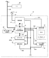
画像処理装置10は、記録用紙に画像を形成する画像形成部12と、原稿画像を読み取る画像読取部14と、ファクシミリ通信制御回路16を備えている。画像処理装置10は、メインコントローラ18を備えており、画像形成部12、画像読取部14、ファクシミリ通信制御回路16を制御して、例えば、画像読取部14で読み取った原稿画像の画像データを一次的に記憶したり、読み取った画像データを画像形成部12又はファクシミリ通信制御回路16へ送出したりする。
The
メインコントローラ18にはインターネット等のネットワーク通信回線網20が接続され、ファクシミリ通信制御回路16には電話回線網22が接続されている。メインコントローラ18は、例えば、ネットワーク通信回線網20を介してホストコンピュータと接続され、画像データを受信したり、ファクシミリ通信制御回路16を介して電話回線網22を用いてファクシミリ受信及びファクシミリ送信を実行する役目を有している。
A
画像読取部14は、原稿を位置決めする原稿台と、原稿台に置かれた原稿の画像を走査して光を照射する走査駆動系と、走査駆動系の走査により反射又は透過する光を受光して電気信号に変換するCCD等の光電変換素子と、が設けられている。
The
画像形成部12は、感光体を備え、感光体の周囲には、感光体を一様に帯電する帯電装置と、画像データに基づいて光ビームを走査する走査露光部と、前記走査露光部によって走査露光されることで形成された静電潜像を現像する画像現像部と、現像化された感光体上の画像を記録用紙へ転写する転写部と、転写後の感光体の表面をクリーニングするクリーニング部と、が設けられている。また、記録用紙の搬送経路上には、転写後の記録用紙上の画像を定着する定着部を備えている。
The
画像処理装置10には、入力電源線24の先端にコンセント26が取り付けられており、壁面Wまで配線された商用電源31の配線プレート32に、当該コンセント26を差し込むことで、画像処理装置10は、商用電源31から、電力の供給を受けるようになっている。
An
(画像処理装置の制御系ハード構成)
図2は、画像処理装置10の制御系のハード構成の概略図である。
(Control system hardware configuration of image processing apparatus)
FIG. 2 is a schematic diagram of the hardware configuration of the control system of the
ネットワーク回線網20は、前記画像処理装置10のメインコントローラ18に接続されている。なお、ネットワーク回路網20には、画像データを送信元等になり得るPC(端末装置)29が接続されている。
The
メインコントローラ18には、それぞれ、データバスやコントロールバス等のバス33A〜33Dを介して、ファクシミリ通信制御回路16、画像読取部14、画像形成部12、UIタッチパネル40が接続されている。すなわち、このメインコントローラ18が主体となって、画像処理装置10の各処理部が制御されるようになっている。なお、UIタッチパネル40には、UIタッチパネル用バックライト部40BLが取り付けられている。
The
また、画像処理装置10は、電源装置42を備えており、メインコントローラ18とは信号ハーネス43で接続されている。
In addition, the
電源装置42は、商用電源31から入力電源線24を介して電力の供給を受けている。
The
電源装置42では、メインコントローラ18、ファクシミリ通信制御回路16、画像読取部14、画像形成部12、UIタッチパネル40のそれぞれに対して独立して電力を供給する電力供給線35A〜35Dが設けられている。このため、メインコントローラ18では、各処理部(デバイス)に対して個別に電力供給(電力供給モード)、或いは電力供給遮断(スリープモード)し、所謂部分節電制御を可能としている。
In the
また、メインコントローラ18は、その一部に常に電力が供給される節電監視制御部(例えば、ICチップ等)があり、当該節電監視制御部には、第1の人感センサ28が接続されており、画像処理装置10の周囲の人の有無を監視している。
The
(人感センサの機能)
ところで、スリープモード時に使用者が画像処理装置10の前に立ち、その後に例えば、節電制御ボタンを操作して、電力供給を再開した場合、画像処理装置10が立ち上がるまでに時間を要する場合があった。
(Function of human sensor)
By the way, when the user stands in front of the
そこで、第1の人感センサ28を設置すると共に、スリープモードでは、使用者が節電解除ボタンを押す前に第1の人感センサ28で検知して早期に電力供給を再開して、使用者が早く使えるようにした。なお、節電制御ボタンと第1の人感センサ28とを併用しているが、第1の人感センサ28のみで全ての監視を行うことも可能である。
Therefore, in addition to installing the first
なお、第1の人感センサ28は、「人感」としているが、これは、本実施の形態に則した固有名詞であり、少なくとも人が感知(検出)できればよく、言い換えれば、人以外の移動体の感知(検出)も含むものである。従って、以下において、第1の人感センサ28の検出対象を「人」に言及する場合があるが、将来的には、人に代わって実行するロボット等も感知対象範囲である。なお、逆に、人と特定して感知できる特殊センサが存在する場合は、当該特殊センサを適用可能である。以下では、移動体、人、使用者等は、第1の人感センサ28が検出する対象として同義として扱い、必要に応じて区別することとする。
The first
「第1の人感センサ28」
本実施の形態に係る第1の人感センサ28の仕様は、画像処理装置10の周囲(例えば、0m〜5mの範囲)において、移動体の動きを検出するものである。この場合、焦電素子の焦電効果を用いた赤外線センサ等が代表的である(焦電型センサ)。本実施の形態では、第1の人感センサ28として焦電型センサを適用している。例えば、検出範囲の温度変化量が、予めしきい値を超えた場合に、出力信号である二値信号が反転する。
"First
The specification of the first
この第1の人感センサ28に適用された焦電素子の焦電効果を用いたセンサの最大の特徴は、検出領域が広いことである。また、移動体の動きを感知するため、検出領域内であって、人が静止していると、温度変化がないので人の存在を検出しない。例えば、人の移動時にハイレベル信号が出力されている場合、検出範囲内の人が静止すると、当該信号がローレベル信号になるものである。
The greatest feature of the sensor using the pyroelectric effect of the pyroelectric element applied to the first
なお、本実施の形態における「静止」とは、スチルカメラ等で撮影した静止画のように完全静止も当然含まれるが、例えば、人が画像処理装置10の前に操作を目的として立ち止まることを含むものとする。従って、予め定めた範囲の微動(呼吸に伴う動き等)や、手足、首等を動かすといった場合を静止の範疇とする。
Note that “still” in the present embodiment naturally includes complete stillness such as a still image taken with a still camera or the like. For example, a person stops before the
但し、人が画像処理装置10の前で、例えば画像形成や画像読取等の処理を待つ間、その場でストレッチ運動等を行うと、第1の人感センサ28では、人の存在を検出する場合もある。また、逆に、人が室内よりも低温度の室外から入ってきた場合、低温度の被服に遮られて、人の温度を検出できない場合もある。この点については、後述する。
However, if a person performs a stretching exercise or the like in front of the
従って、当該「静止」を定義して第1の人感センサ28による動き検出のためのしきい値を設定するのではなく、しきい値は比較的おおまか、かつ標準的に設定し、環境(温度、湿度等)に基づく、当該第1の人感センサ28の検出状態に依存するようにしてもよい。すなわち、装置設置場所において、実験的に又は統計的に、第1の人感センサ28が二値信号の内の1つ(例えば、ハイレベル信号)を出力しているときは人が動いていることを示し、第1の人感センサ28の検出領域内に人が存在し、かつ二値信号の内の他の1つ(例えば、ローレベル信号)が出力された場合を静止とするようなしきい値を設定すればよい。
Therefore, instead of defining the “still” and setting a threshold value for motion detection by the first
なお、第1の人感センサ28として、以下に示す機能をそれぞれ達成することが可能であれば、第1の人感センサ28として焦電型センサに限定されるものではない。
The first
本実施の形態では、第1の人感センサ28が管轄する検出領域内に移動体(使用者)が進入した時点でスリープモードからスタンバイモードへの立ち上げを指示する。
In the present embodiment, when the moving body (user) enters the detection area controlled by the first
一方、第1の人感センサ28の電力供給の遮断に関しては、当該第1の人感センサ28の移動体検出状況に加え、タイマ機能が併用されるようになっている。
On the other hand, regarding the interruption of the power supply of the first
(第1の人感センサ28及びその周辺の構成)
図3に示される如く、画像処理装置10は、画像読取装置14と、画像形成装置12等が筐体300に覆われており、第1の人感センサ28は、当該筐体300における、縦長矩形状のピラー部302に取り付けられている。ピラー部302は、前記画像読取装置14を覆う上筐体300Aと画像形成装置12を覆う下筐体300Bとを連結する部分であり、その内部は記録用紙搬送系等が組み付けられている。
(Configuration of the first
As shown in FIG. 3, in the
ピラー部302の前面は、前記ピラー部302を意匠的な要素を持って被覆する縦長の矩形状のカバー部材304が取り付けられている。図4に示される如く、カバー部材304の裏面側には、前記第1の人感センサ28が取り付けられたセンサ組み付け用の構造体308(図6参照)を具備する。
A vertically long
図5に示される如く、カバー部材304の下面と、前記下筐体300Bの上面との間には、隙間部312が設けられている。また、カバー部材304の図5の下端部は所謂面取り加工(面取り部304A)形状とされ、前記隙間部312の開口面積が、奥側の隙間寸法よりも大きくなっている。
As shown in FIG. 5, a
前記面取り部304Aには矩形状の貫通孔304Bが設けられている。貫通孔304Bは、面取り部304Aに形成されているため、前面に形成されているよりも、装置前方からは見えにくく、カバー部材304の意匠的な要素を損なわない構造となっている。
The chamfered
また、前記構造体308には第1の人感センサ28が取り付けられており、当該第1の人感センサ28の検出部28Aの検出面(詳細後述)の中心光軸(法線L)は水平とされ、この法線Lよりも下方に貫通孔304Bが設けられている。このため、貫通孔304Bは、前記第1の人感センサ28により移動体を検出するための下向きの監視窓としての役目を有する。
Further, the first
また、カバー部材304における、前記法線Lよりも上方には、貫通孔304Cが設けられている。この貫通孔304Cは、前記第1の人感センサ28により移動体を検出するための上向きの監視窓としての役目を有する。以下、貫通孔304B、貫通孔304Cを総称して監視窓304という場合がある。
A through
第1の人感センサ28は、検出部28Aと回路基板部28Bとを備えており、回路基板部28Bがカバー部材304と平行に配置された構造体308に取り付けられている。このため、検出部28Aの検出面の中心光軸(法線L)は水平となり、カバー部材304の前面(裏面側)に対向しているが、この部分は遮蔽されている。
The first
図6(A)は、本実施の形態に適用される第1の人感センサ28(焦電センサ)の検出部28Aの検出面正面図であり、検出部28Aは複数の検出素子の集合体(本実施の形態では、16個の検出素子314A,314B,314C,314D,314E,314F,314G,314H,314I,314J,314K,314L,314M,314N,314O,314Pの集合体)である。以下、総称する場合、検出素子314という。
FIG. 6A is a front view of the detection surface of the
検出素子314は、それぞれ赤外線を検出可能であり、回路基板部28B(図5参照)によって、それぞれの検出素子314に入力される赤外線の変化量である電気信号が合成され、単一のセンサの電気信号として出力されるようになっている。
Each of the
検出部28Aは、弾丸型(先端部が半球形状の筒体型)のレンズカバー316(図5参照)によって被覆されている。レンズカバー316の先端部の半球形状面は、検出素子314の数(ここでは、16個)に応じて区画されたレンズ部318A〜318P(図6(B)参照、以下、総称する場合「レンズ部318)が形成されている。このため、レンズ部318によって集光されたそれぞれの領域内が、それぞれ対応する検出素子314の検出領域となる。検出領域は、少なくとも互いに主たる領域(仕様上の検出領域)が同一の領域となっている。検出素子314が有効に利用されればされるほど、出力される電気信号の強度(精度)が高くなる。
The
ところで、図5及び図6(B)、(C)に示される如く、第1の人感センサ28の正面は、カバー部材304の前面の裏面側304Dによって遮蔽されているため、検出素子314の一部(図6(B)では、上部及び下部のそれぞれ1/3程度の検出素子が監視窓304Bから赤外線を検出することが可能な有効検出素子となる。具体的には、上部の1/3は検出素子314A、314B、314C、314Dであり、下部の1/3は検出素子314J、314N、314O、314Pである。
Incidentally, as shown in FIGS. 5 and 6B and 6C, the front surface of the first
言い換えれば、それ以外の検出素子314E、314F、314G、314H、314I、314K、314L、314Mは赤外線が検出不可能な無効検出素子となる。
In other words, the
なお、当然全て(16個)の検出素子314A〜314Pの合成信号強度(例えば、電圧値)を用いることが検出精度からすれば好ましいが、1個の検出素子の信号強度であっても、2個以上の検出素子の信号強度よりも検出精度は落ちるが、移動体を検出するのに十分な信号強度にを確保することは実証済みである。
Of course, it is preferable from the viewpoint of detection accuracy to use the combined signal intensity (for example, voltage value) of all (16)
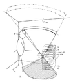
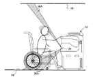
図7、図8に示される如く、第1の人感センサ28の検出領域(検出範囲)は、画像処理装置10の設置された床面56と、天井面58とに向けられた、2つの互いに分離された下側領域56Aと、上側領域58Aとに設定されることになる。
As shown in FIG. 7 and FIG. 8, the detection area (detection range) of the first
ここで、下側領域56Aは、その検出範囲の到達位置が床面56であり、画像処理装置10に接近してくる移動体(使用者60)の接地部(足下)を対象としている。
Here, the
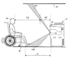
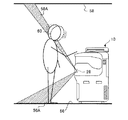
第1の人感センサ28は、検出範囲内の温度変化を検出するため、移動体(使用者60)を検出するには、当該移動体(使用者60)が動いている必要がある。ところが、足下の場合(例えば、図9、図10のように、使用者60が画像処理装置10の前に対峙し、UIタッチパネル40等を操作している場合)では、第1の人感センサ28が温度変化を検出できない場合がある。
Since the first
そこで、本実施の形態では、第1の人感センサ28の検出範囲として、下側領域56Aに加え、上側領域58Aを設定した。この上側領域58Aの最終到達点は、天井面58であるが、当該天井面58に至るまでの空間領域に、移動体(使用者60)の中で最も動きがあると予測される頂部(頭部)が進入することを想定したものである(図9、図10参照)。
Therefore, in the present embodiment, as the detection range of the first
なお、図7,図8に示される如く、下側領域56Aによって使用者60の足下を検出するときの画像処理装置10からの最長距離Aは、上側側領域58Aによって使用者60の頭部を検出するときの画像処理装置10からの最長距離B1(図7参照)、並びにB2(図8参照)よりも長くし、使用者60の最大高さ寸法の違いによる検出時期の差(例えば、図7の距離C1と図8の距離C2の差等であり、距離C1<距離C2)を解消するようにしている。
As shown in FIGS. 7 and 8, the longest distance A from the
以下、本実施の形態の作用を説明する。 Hereinafter, the operation of the present embodiment will be described.
(画像処理装置10(デバイス)の電力供給制御のモード遷移の一例)
画像処理装置10は、処理がなされていないと動作状態は、スリープモードとなる。
(Example of mode transition of power supply control of image processing apparatus 10 (device))
If the
ここで、立ち上げ契機(第2の人感センサ30による使用者検出等の立ち上げトリガの検出、或いは節電制御ボタン等の操作)があると、動作状態はウォームアップモードへ遷移する。 Here, if there is a startup opportunity (detection of a startup trigger such as user detection by the second human sensor 30 or operation of a power saving control button or the like), the operating state transitions to the warm-up mode.
なお、この立ち上げトリガ契機後は、メインコントローラ18及びUIタッチパネル40BLの起動によって、本来のスリープモード時の電力供給よりも電力供給量が増加するモードを設けてもよい。このモードは、依然としてスリープモードと定義してもよいし、他のモードとして定義してもよい。
Note that a mode in which the power supply amount is increased from the power supply in the original sleep mode by activation of the
また、立ち上げトリガ契機後、例えば、節電制御ボタンの操作によって復帰すると、ジョブを選択するモードまで復帰し、選択されたジョブによってどのデバイスが起動するかが決まり、画像形成部12が起動しない場合はウォームアップしない場合もある。
In addition, after the start trigger is triggered, for example, when returning by the operation of the power saving control button, the mode returns to the mode for selecting a job, the device to be activated is determined by the selected job, and the
前記立ち上げのトリガとしては、第1の人感センサ28による使用者検出、使用者の節電制御ボタンの操作による節電解除操作の他、例えば、ICカードリーダの操作認証であってもよい。
The start-up trigger may be, for example, an operation authentication of an IC card reader, in addition to a user detection by the first
前記ウォームアップモードは画像処理装置10(主として、画像形成部240の定着部の温度)を迅速に処理可能状態にもっていくための暖気運転であり、各モードの内最大の電力消費量となるが、例えば、定着部におけるヒータとしてIHヒータを利用することによって、ハロゲンランプを用いたヒータよりもウォームアップモード時間は、比較的短い時間とされている。なお、IHヒータとハロゲンランプの併用も可能である。なお、暖気運転は、最も電力を消費するモードである(例えば、1200W)。 The warm-up mode is a warm-up operation for quickly bringing the image processing apparatus 10 (mainly the temperature of the fixing unit of the image forming unit 240) into a processable state, and has the maximum power consumption in each mode. For example, by using an IH heater as a heater in the fixing unit, the warm-up mode time is relatively shorter than that of a heater using a halogen lamp. An IH heater and a halogen lamp can be used in combination. The warm-up operation is a mode that consumes the most power (for example, 1200 W).
ウォームアップモードによる暖機運転が終了すると、画像処理装置10はスタンバイモードに遷移する。
When the warm-up operation in the warm-up mode ends, the
スタンバイモードは、文字通り「事に備えて準備が完了している」モードであり、画像処理装置10においては、画像処理の動作が即実行できる状態となっている。
The standby mode is literally a “preparation is complete in preparation” mode, and the
このため、キー入力としてジョブ実行操作があると、画像処理装置10の動作状態は、ランニングモードに遷移し、指示されたジョブに基づく画像処理が実行されるようになっている。
For this reason, when there is a job execution operation as a key input, the operation state of the
画像処理が終了すると(連続した複数のジョブが待機している場合は、その連続したジョブの全てが終了したとき)、待機トリガによって画像処理装置10の動作状態はスタンバイモードへ遷移する。なお、画像処理後、タイマ機能による計時を開始し、予め定めた時間経過した後に待機トリガを出力し、スタンバイモードへ遷移するようにしてもよい。
When the image processing is completed (when a plurality of continuous jobs are waiting, when all the continuous jobs are completed), the operation state of the
このスタンバイモード中にジョブ実行指示があれば、再度ランニングモードへ遷移し、立ち下げのトリガ検出、或いは予め定めた時間が経過したとき、スリープモードへ遷移するようになっている。なお、立ち下げのためのトリガは、例えば、第1の人感センサ28による検出結果に基づく信号やタイマ機能、並びにこれらの併用が可能である。
If there is a job execution instruction in the standby mode, the mode is changed to the running mode again, and when the fall trigger is detected or a predetermined time has elapsed, the mode is changed to the sleep mode. The trigger for falling can be, for example, a signal based on a detection result by the first
また、画像処理装置10における実際の動作におけるモード状態の遷移が、全て単一のタイミングチャートのとおり時系列で進行するものではない。例えば、ウォームアップモード後のスタンバイモードで処理が中止され、スリープモードへ移行する場合もある。
Further, the transition of the mode state in the actual operation in the
このように、本実施の形態の画像処理装置10は、モードの間を相互に遷移しており、各モード毎に消費される電力が異なっている。
As described above, the
また、本実施の形態では、各デバイス毎に電力供給制御が行われることで、例えば、スリープモードから画像読取処理が指示された場合には、画像形成部12を起動することなく、画像読取部14を通電するといった、所謂部分節電が可能である。
In the present embodiment, power supply control is performed for each device. For example, when an image reading process is instructed from the sleep mode, the image reading unit is not started without starting the
(スリープモード中における第1の人感センサ28での監視)
ここで、本実施の形態では、スリープモード中は、基本的には、第1の人感センサ28のみが電力供給を受けて、移動体の接近状態を監視している。
(Monitoring by the first
Here, in the present embodiment, during the sleep mode, basically, only the first
この第1の人感センサ28によって移動体(使用者60)を検出すると(図7,図8に示すように検出範囲に立ち入った状態)、画像処理装置10を使用する使用者であることを認識し、画像処理装置10の一部(例えば、メインコントローラ18とUIタッチパネル40等)又は全部に電力を供給する。
When the moving object (user 60) is detected by the first human sensor 28 (in a state where the user enters the detection range as shown in FIGS. 7 and 8), the user who uses the
ここで、本実施の形態では、図7、図8に示される如く、第1の人感センサ28の検出領域を、下側領域56Aと上側領域58Aとに区画した。
Here, in this embodiment, as shown in FIGS. 7 and 8, the detection area of the first
通常、近づいてくる移動体(人)を検知するには、その足元を確実に検出可能な床面56側、すなわち下側領域56Aを検出範囲とすればよい。しかしながら、第1の人感センサ28は、検出範囲内の温度変化を検出するため、移動体が立ち止まると温度変化がなくなり、第1の人感センサ28が温度変化を検出できない場合がある。
Usually, in order to detect a moving body (person) approaching, the detection area may be the
そこで、本実施の形態では、第1の人感センサ28の検出範囲として、下側領域56Aに加え、上側領域58Aを設定し、移動体(使用者であれば人)の足下に加え、頭部を検出対象とした。
Therefore, in the present embodiment, as the detection range of the first
このように、本実施の形態では、第1の人感センサ28の検出範囲として、床面56に向けられた下側領域56Aでの検出範囲と、天井面58に向けられた上側領域58Aでの検出範囲とに区画し、例えば、移動体(使用者60)が画像処理装置10のUIタッチパネル40に対峙して操作するとき、足下が静止状態となっても(図7、図8参照)、頭部は完全に静止することは、足下よりも少なくため(図9、図10参照)、当該UIタッチパネル40等の操作をしている使用者60が認識可能となる。
As described above, in the present embodiment, the detection range of the first
なお、本実施の形態では、第1の人感センサ28の検出範囲を、下側領域56Aと上側領域58Aとに分割し、それぞれの検出距離を異ならせている。すなわち、下側領域56Aによって使用者60の足下を検出するときの画像処理装置10からの最長距離Aは、上側領域58Aによって使用者60の頭部を検出するときの画像処理装置10からの最長距離B1、B2よりも長い。すなわち、足下の方が頭部よりも検出位置が遠い。
In the present embodiment, the detection range of the first
これにより、使用者60の最大寸法の違いによる検出時期の差(例えば、図7の距離C1と図8の距離C2の差等であり、距離C1<距離C2)が解消される。 As a result, the difference in detection timing due to the difference in the maximum dimension of the user 60 (for example, the difference between the distance C1 in FIG. 7 and the distance C2 in FIG. 8, etc., distance C1 <distance C2) is eliminated.
(変形例)
本実施の形態では、第1の人感センサ28の検出素子314において、上側領域58Aは、検出素子314A、314B、314C、314Dで検出し、下側領域56Aは、検出素子314J、314N、314O、314Pで検出している。
(Modification)
In the present embodiment, in the
この場合、検出素子314A、314B、314C、314Dの個体差による信号強度と、検出素子314J、314N、314O、314Pの固体差による信号強度が異なり、検出基準(検出しきい値)が上側領域58Aと下側領域56Aとで異なる場合がある。
In this case, the signal intensity due to the individual difference between the
そこで、変形例では、図11に示される如く、下筐体300Bにおけるピラー部302に対向する上面に、反射ミラー320(光学部材)を配置して、上側領域58Aと下側領域56Aを検出する検出素子を共通とした(図11では、検出素子314A、314B、314C、314D)。
Therefore, in the modified example, as shown in FIG. 11, a reflection mirror 320 (optical member) is arranged on the upper surface of the
すなわち、下側領域56Aは、光軸が直接前記貫通孔304Bを通過する。一方、上側領域58Aは、光軸が反射ミラー320により反射して偏向する。
That is, in the
なお、「偏向」とは、光軸を前記反射ミラー320で反射することに加え、レンズ、プリズム等によって屈折させることも含むが、光軸を軸回りに回転させる「偏光」とは異なる。
Note that “deflection” includes not only reflection of the optical axis by the
この変形例によれば、ピラー部302の開口として、面取り部304Aに設けた貫通孔304Bのみであるので(貫通孔304Cが不要であるので)、ピラー部302の正面視における意匠的な要素に影響を及ぼす加工が不要となる。
According to this modification, since only the through
W 壁面
10 画像処理装置
12 画像形成部
14 画像読取部
16 ファクシミリ通信制御回路
18 メインコントローラ
20 ネットワーク通信回線網
22 電話回線網
24 入力電源線
26 コンセント
28 第1の人感センサ
28A 検出部
28B 回路基板部
31 商用電源
32 配線プレート
33A〜33D バス
35A〜35D 電力供給線
40 UIタッチパネル
40BL UIタッチパネル用バックライト部
42 電源装置
43 信号ハーネス
56 床面
58 天井面
56A 下側領域
58A 上側領域
60 使用者
300 筐体
302 ピラー部
300A 上筐体
300B 下筐体
304 カバー部材
308 構造体
304A 面取り部
304B 貫通孔
304C 貫通孔
314(314A〜314P) 検出素子
316 レンズカバー
318(318A〜318P) レンズ部
Claims (5)
前記制御部の一部に属し常に電力が供給されることで前記移動体検出手段による移動体の接近を監視すると共に、当該移動体検出手段で移動体を検出した時点で、前記制御部の他の一部を含む前記処理装置本体に設けられた電力供給対象に電力供給を指示する電力供給制御手段と、
を有し、
前記移動体検出手段が、
前記下側領域により、操作者の足下の動きを検出することで、前記処理装置本体に接近している操作者を検出可能とし、
前記上側領域により、操作者の頭部の動きを検出することで、前記処理装置本体に対峙している操作者を検出可能とした電力供給制御装置。 A plurality of power supply objects and a processing apparatus main body provided with a control unit that controls the power supply object, and a movable body that moves around the processing apparatus body can be detected. A moving body detection means partitioned into a lower area which is a downward detection range for detecting a ground contact portion of the moving body and an upper area which is an upward detection range for detecting the top of the moving body;
The mobile unit detection means monitors the approach of the moving body by being always supplied with power and belongs to a part of the control unit, and at the time when the moving body detection unit detects the moving body, a power supply control means for instructing the power supply to the power supply target provided in the processing apparatus main body including a part of,
Have
The moving body detecting means is
By detecting the movement of the operator's feet by the lower region, it is possible to detect the operator approaching the processing apparatus body,
An electric power supply control device capable of detecting an operator confronting the processing device main body by detecting a movement of the operator's head by the upper region.
前記検出素子には遮蔽部が対峙され、遮蔽部には、前記上向きの検出範囲と下向きの検出範囲とでそれぞれ異なる検出開口部が設けられている請求項1又は請求項2記載の電力供給制御装置。 The moving body detection means includes a plurality of detection elements each having a unique detection region, and combines detection signals from the plurality of detection elements to generate a single detection signal,
The power supply control according to claim 1, wherein a shielding portion is opposed to the detection element, and the detection portion is provided with a different detection opening in the upward detection range and the downward detection range. apparatus.
前記検出素子には遮蔽部が対峙され、遮蔽部には、前記上向き又は下向きの一方の検出範囲に対応する検出開口部が設けられ、その一部の光軸が反射ミラーによって前記上向き又は下向きの他方に偏向されている請求項1又は請求項2記載の電力供給制御装置。 The moving body detection means includes a plurality of detection elements each having a unique detection region, and combines detection signals from the plurality of detection elements to generate a single detection signal,
The detection element is opposed to a shielding portion, and the shielding portion is provided with a detection opening corresponding to one of the upward and downward detection ranges, and a part of the optical axis is directed upward or downward by a reflecting mirror. The power supply control device according to claim 1 or 2, wherein the power supply control device is deflected to the other side.
前記制御部により、前記処理部が個別に電力供給状態並びに電力遮断状態に遷移するように制御され、処理部別に節電する部分節電手段を有する画像処理装置。 5. The power supply control device according to claim 1, wherein the processing device main body reads an image from a document image, and forms an image on a recording sheet based on the image information. Including at least one processing unit, an image forming processing unit, a facsimile communication processing unit that transmits and receives images under a predetermined communication procedure,
An image processing apparatus comprising: a partial power saving unit that is controlled by the control unit so that the processing unit individually transitions to a power supply state and a power cut-off state, and saves power for each processing unit.
Priority Applications (4)
| Application Number | Priority Date | Filing Date | Title |
|---|---|---|---|
| JP2012110754A JP6044113B2 (en) | 2012-05-14 | 2012-05-14 | Power supply control device, image processing device |
| US13/676,670 US9461503B2 (en) | 2012-05-14 | 2012-11-14 | Power supply control device, image processing apparatus, and power supply control method |
| CN201210525730.4A CN103428388B (en) | 2012-05-14 | 2012-12-07 | Power supply control device, image processing apparatus and power supply control method |
| US15/255,315 US10277065B2 (en) | 2012-05-14 | 2016-09-02 | Power supply control device, image processing apparatus, and power supply control method |
Applications Claiming Priority (1)
| Application Number | Priority Date | Filing Date | Title |
|---|---|---|---|
| JP2012110754A JP6044113B2 (en) | 2012-05-14 | 2012-05-14 | Power supply control device, image processing device |
Publications (3)
| Publication Number | Publication Date |
|---|---|
| JP2013237179A JP2013237179A (en) | 2013-11-28 |
| JP2013237179A5 JP2013237179A5 (en) | 2015-05-14 |
| JP6044113B2 true JP6044113B2 (en) | 2016-12-14 |
Family
ID=49548082
Family Applications (1)
| Application Number | Title | Priority Date | Filing Date |
|---|---|---|---|
| JP2012110754A Active JP6044113B2 (en) | 2012-05-14 | 2012-05-14 | Power supply control device, image processing device |
Country Status (3)
| Country | Link |
|---|---|
| US (2) | US9461503B2 (en) |
| JP (1) | JP6044113B2 (en) |
| CN (1) | CN103428388B (en) |
Families Citing this family (10)
| Publication number | Priority date | Publication date | Assignee | Title |
|---|---|---|---|---|
| US9116484B2 (en) * | 2012-09-03 | 2015-08-25 | Konica Minolta, Inc. | Image forming apparatus, power control method, and recording medium |
| JP6214174B2 (en) * | 2013-03-08 | 2017-10-18 | キヤノン株式会社 | Image processing apparatus and control method |
| JP6521558B2 (en) * | 2013-04-04 | 2019-05-29 | キヤノン株式会社 | Image forming apparatus, control method of image forming apparatus, program, and recording medium |
| US9554958B2 (en) * | 2013-12-11 | 2017-01-31 | General Electric Company | System and method for detection of infant presence |
| JP2015154377A (en) * | 2014-02-18 | 2015-08-24 | キヤノン株式会社 | Image processing device, control method for image processing device and program |
| JP6123784B2 (en) * | 2014-12-25 | 2017-05-10 | コニカミノルタ株式会社 | Image forming apparatus, power saving state control method, and program |
| US10012548B2 (en) * | 2015-11-05 | 2018-07-03 | Google Llc | Passive infrared sensor self test with known heat source |
| JP6843542B2 (en) * | 2016-07-29 | 2021-03-17 | キヤノン株式会社 | Devices, methods and programs that detect people using ultrasonic sensors |
| JP6703049B2 (en) * | 2018-07-25 | 2020-06-03 | キヤノン株式会社 | Information processing apparatus and method of controlling information processing apparatus |
| JP2021196222A (en) * | 2020-06-11 | 2021-12-27 | 東芝テック株式会社 | Sensor unit and image processor |
Family Cites Families (21)
| Publication number | Priority date | Publication date | Assignee | Title |
|---|---|---|---|---|
| JPS58207148A (en) * | 1982-05-27 | 1983-12-02 | Ricoh Co Ltd | Business work device |
| JP2763572B2 (en) * | 1989-03-28 | 1998-06-11 | 株式会社リコー | Office equipment operator detection device |
| JPH0659040A (en) * | 1992-08-05 | 1994-03-04 | Ricoh Co Ltd | Image forming device |
| JPH06242226A (en) * | 1993-02-20 | 1994-09-02 | Ricoh Co Ltd | Method of detecting operator, apparatus for detecting operator, and image forming apparatus |
| JPH07110534A (en) * | 1993-08-16 | 1995-04-25 | Ricoh Co Ltd | Image reader |
| JPH09166943A (en) * | 1995-12-14 | 1997-06-24 | Ricoh Co Ltd | Image forming device |
| JP3835771B2 (en) * | 1996-03-15 | 2006-10-18 | 株式会社東芝 | Communication apparatus and communication method |
| JP2004089631A (en) * | 2002-07-12 | 2004-03-25 | Toto Ltd | Toilet seat device |
| JP2005017938A (en) * | 2003-06-27 | 2005-01-20 | Murata Mach Ltd | Image processing device |
| JP2005037296A (en) * | 2003-07-17 | 2005-02-10 | Asahi Matsushita Electric Works Ltd | Infrared sensor device and lighting apparatus |
| KR100968669B1 (en) * | 2006-05-31 | 2010-07-06 | 샤프 가부시키가이샤 | Display system |
| JP5022661B2 (en) * | 2006-10-06 | 2012-09-12 | 日立オムロンターミナルソリューションズ株式会社 | Suspicious object detection method and transaction apparatus |
| JP5163249B2 (en) * | 2008-04-11 | 2013-03-13 | 富士電機株式会社 | vending machine |
| JP5053188B2 (en) * | 2008-06-18 | 2012-10-17 | 株式会社リコー | Input device and image forming apparatus |
| JP2010047987A (en) * | 2008-08-21 | 2010-03-04 | Toto Ltd | Urinal |
| JP5300451B2 (en) * | 2008-12-17 | 2013-09-25 | キヤノン株式会社 | Image processing apparatus and image processing apparatus control method |
| JP5424676B2 (en) * | 2009-03-13 | 2014-02-26 | キヤノン株式会社 | Image processing device |
| JP4949453B2 (en) * | 2009-11-12 | 2012-06-06 | シャープ株式会社 | Image processing apparatus and image processing apparatus control method |
| JP5793994B2 (en) * | 2011-06-27 | 2015-10-14 | 富士ゼロックス株式会社 | Image forming apparatus |
| US8994229B2 (en) * | 2011-12-14 | 2015-03-31 | Optex Inc. | Wireless non-contact switch for automatic doors |
| JP5970230B2 (en) * | 2012-05-08 | 2016-08-17 | アツミ電氣株式会社 | Ranging type security sensor |
-
2012
- 2012-05-14 JP JP2012110754A patent/JP6044113B2/en active Active
- 2012-11-14 US US13/676,670 patent/US9461503B2/en active Active
- 2012-12-07 CN CN201210525730.4A patent/CN103428388B/en active Active
-
2016
- 2016-09-02 US US15/255,315 patent/US10277065B2/en active Active
Also Published As
| Publication number | Publication date |
|---|---|
| US20130300198A1 (en) | 2013-11-14 |
| US20160372968A1 (en) | 2016-12-22 |
| JP2013237179A (en) | 2013-11-28 |
| CN103428388A (en) | 2013-12-04 |
| US9461503B2 (en) | 2016-10-04 |
| US10277065B2 (en) | 2019-04-30 |
| CN103428388B (en) | 2018-06-29 |
Similar Documents
| Publication | Publication Date | Title |
|---|---|---|
| JP6044113B2 (en) | Power supply control device, image processing device | |
| JP5929023B2 (en) | Power supply control device, image processing device, power supply control program | |
| JP5983261B2 (en) | Power supply control device, image processing device, power supply control program | |
| JP5870795B2 (en) | Moving body detection device, power supply control device, image processing device | |
| US9497346B2 (en) | Power supply control apparatus, image processing apparatus, and non-transitory computer readable medium | |
| JP5146568B2 (en) | Power supply control device, image processing device, power supply control program | |
| JP5803470B2 (en) | Power supply control device, image processing device, power supply control program | |
| JP5906878B2 (en) | Power supply control device, image processing device, power supply control program | |
| JP5998831B2 (en) | Power supply control device, image processing device, power supply control program | |
| JP5998830B2 (en) | Power supply control device, image processing device, power supply control program | |
| JP5884434B2 (en) | Power supply control device, image processing device, power supply control program | |
| JP5045830B2 (en) | Power supply control device, image processing device, power supply control program | |
| JP5957844B2 (en) | Power supply control device, image processing device, power supply control program | |
| JP5942624B2 (en) | Power supply control device, image processing device, power supply control program | |
| JP6160728B2 (en) | Power supply control device, power management control program | |
| JP6011035B2 (en) | Power supply control device, image processing device | |
| JP2017165103A (en) | Processing apparatus and processing program | |
| JP6137367B2 (en) | Processing equipment | |
| JP2016145995A (en) | Power supply control device, image processing device, and power supply control program | |
| JP6191730B2 (en) | Power supply control device, image processing device, power supply control program | |
| JP6065769B2 (en) | Power display module, image processing apparatus, power monitoring control program | |
| JP2019061258A (en) | Processing apparatus and processing program | |
| JP2015233295A (en) | Power supply control device, image processing device, power supply control program |
Legal Events
| Date | Code | Title | Description |
|---|---|---|---|
| A621 | Written request for application examination |
Free format text: JAPANESE INTERMEDIATE CODE: A621 Effective date: 20150306 |
|
| A521 | Written amendment |
Free format text: JAPANESE INTERMEDIATE CODE: A523 Effective date: 20150325 |
|
| A131 | Notification of reasons for refusal |
Free format text: JAPANESE INTERMEDIATE CODE: A131 Effective date: 20151215 |
|
| A521 | Written amendment |
Free format text: JAPANESE INTERMEDIATE CODE: A523 Effective date: 20160210 |
|
| A131 | Notification of reasons for refusal |
Free format text: JAPANESE INTERMEDIATE CODE: A131 Effective date: 20160621 |
|
| A521 | Written amendment |
Free format text: JAPANESE INTERMEDIATE CODE: A523 Effective date: 20160817 |
|
| TRDD | Decision of grant or rejection written | ||
| A01 | Written decision to grant a patent or to grant a registration (utility model) |
Free format text: JAPANESE INTERMEDIATE CODE: A01 Effective date: 20161018 |
|
| A61 | First payment of annual fees (during grant procedure) |
Free format text: JAPANESE INTERMEDIATE CODE: A61 Effective date: 20161031 |
|
| R150 | Certificate of patent or registration of utility model |
Ref document number: 6044113 Country of ref document: JP Free format text: JAPANESE INTERMEDIATE CODE: R150 |
|
| S533 | Written request for registration of change of name |
Free format text: JAPANESE INTERMEDIATE CODE: R313533 |
|
| R350 | Written notification of registration of transfer |
Free format text: JAPANESE INTERMEDIATE CODE: R350 |