JP6042556B2 - Method and apparatus for constrained disparity vector derivation in 3D video coding - Google Patents
Method and apparatus for constrained disparity vector derivation in 3D video coding Download PDFInfo
- Publication number
- JP6042556B2 JP6042556B2 JP2015542150A JP2015542150A JP6042556B2 JP 6042556 B2 JP6042556 B2 JP 6042556B2 JP 2015542150 A JP2015542150 A JP 2015542150A JP 2015542150 A JP2015542150 A JP 2015542150A JP 6042556 B2 JP6042556 B2 JP 6042556B2
- Authority
- JP
- Japan
- Prior art keywords
- view
- generated
- inter
- prediction
- filter
- Prior art date
- Legal status (The legal status is an assumption and is not a legal conclusion. Google has not performed a legal analysis and makes no representation as to the accuracy of the status listed.)
- Active
Links
- 239000013598 vector Substances 0.000 title claims description 107
- 238000000034 method Methods 0.000 title claims description 45
- 238000009795 derivation Methods 0.000 title description 12
- 230000015572 biosynthetic process Effects 0.000 claims description 11
- 238000003786 synthesis reaction Methods 0.000 claims description 11
- 230000001419 dependent effect Effects 0.000 claims description 7
- 208000037170 Delayed Emergence from Anesthesia Diseases 0.000 claims description 2
- 230000002123 temporal effect Effects 0.000 description 18
- 238000010586 diagram Methods 0.000 description 12
- 238000012360 testing method Methods 0.000 description 12
- 230000008569 process Effects 0.000 description 7
- 238000005516 engineering process Methods 0.000 description 5
- 230000006835 compression Effects 0.000 description 4
- 238000012545 processing Methods 0.000 description 4
- 230000003044 adaptive effect Effects 0.000 description 3
- 238000007906 compression Methods 0.000 description 3
- 238000005286 illumination Methods 0.000 description 3
- 230000008901 benefit Effects 0.000 description 2
- 230000005540 biological transmission Effects 0.000 description 2
- 239000000872 buffer Substances 0.000 description 2
- 238000004891 communication Methods 0.000 description 2
- 238000013461 design Methods 0.000 description 2
- 238000001914 filtration Methods 0.000 description 2
- 230000003287 optical effect Effects 0.000 description 2
- 230000009467 reduction Effects 0.000 description 2
- 238000000926 separation method Methods 0.000 description 2
- 238000013459 approach Methods 0.000 description 1
- 230000015556 catabolic process Effects 0.000 description 1
- 239000003086 colorant Substances 0.000 description 1
- 238000006731 degradation reaction Methods 0.000 description 1
- 238000011161 development Methods 0.000 description 1
- 230000002708 enhancing effect Effects 0.000 description 1
- 230000006870 function Effects 0.000 description 1
- 238000005259 measurement Methods 0.000 description 1
- 238000012986 modification Methods 0.000 description 1
- 230000004048 modification Effects 0.000 description 1
- 238000012795 verification Methods 0.000 description 1
- 230000000007 visual effect Effects 0.000 description 1
Images


Classifications
-
- H—ELECTRICITY
- H04—ELECTRIC COMMUNICATION TECHNIQUE
- H04N—PICTORIAL COMMUNICATION, e.g. TELEVISION
- H04N19/00—Methods or arrangements for coding, decoding, compressing or decompressing digital video signals
- H04N19/50—Methods or arrangements for coding, decoding, compressing or decompressing digital video signals using predictive coding
- H04N19/597—Methods or arrangements for coding, decoding, compressing or decompressing digital video signals using predictive coding specially adapted for multi-view video sequence encoding
-
- H—ELECTRICITY
- H04—ELECTRIC COMMUNICATION TECHNIQUE
- H04N—PICTORIAL COMMUNICATION, e.g. TELEVISION
- H04N13/00—Stereoscopic video systems; Multi-view video systems; Details thereof
- H04N13/10—Processing, recording or transmission of stereoscopic or multi-view image signals
- H04N13/106—Processing image signals
- H04N13/161—Encoding, multiplexing or demultiplexing different image signal components
-
- H—ELECTRICITY
- H04—ELECTRIC COMMUNICATION TECHNIQUE
- H04N—PICTORIAL COMMUNICATION, e.g. TELEVISION
- H04N19/00—Methods or arrangements for coding, decoding, compressing or decompressing digital video signals
- H04N19/10—Methods or arrangements for coding, decoding, compressing or decompressing digital video signals using adaptive coding
- H04N19/169—Methods or arrangements for coding, decoding, compressing or decompressing digital video signals using adaptive coding characterised by the coding unit, i.e. the structural portion or semantic portion of the video signal being the object or the subject of the adaptive coding
- H04N19/17—Methods or arrangements for coding, decoding, compressing or decompressing digital video signals using adaptive coding characterised by the coding unit, i.e. the structural portion or semantic portion of the video signal being the object or the subject of the adaptive coding the unit being an image region, e.g. an object
- H04N19/176—Methods or arrangements for coding, decoding, compressing or decompressing digital video signals using adaptive coding characterised by the coding unit, i.e. the structural portion or semantic portion of the video signal being the object or the subject of the adaptive coding the unit being an image region, e.g. an object the region being a block, e.g. a macroblock
-
- H—ELECTRICITY
- H04—ELECTRIC COMMUNICATION TECHNIQUE
- H04N—PICTORIAL COMMUNICATION, e.g. TELEVISION
- H04N19/00—Methods or arrangements for coding, decoding, compressing or decompressing digital video signals
- H04N19/50—Methods or arrangements for coding, decoding, compressing or decompressing digital video signals using predictive coding
- H04N19/503—Methods or arrangements for coding, decoding, compressing or decompressing digital video signals using predictive coding involving temporal prediction
- H04N19/51—Motion estimation or motion compensation
- H04N19/513—Processing of motion vectors
- H04N19/517—Processing of motion vectors by encoding
- H04N19/52—Processing of motion vectors by encoding by predictive encoding
Description
この出願は、2012年11月16日に出願された“Controlling of disparity vector constraint for video coding ”と題された米国特許仮出願番号61/727220号、および、2013年1月24日に出願された“Inter-view signal prediction conditional on disparity vector constraints for video ”と題された米国特許仮出願番号61/756043号から、優先権を主張するものであり、その内容は引用によって本願に援用される。 This application was filed on Nov. 16, 2012, US Provisional Application No. 61/727220 entitled “Controlling of disparity vector constraint for video coding” and on Jan. 24, 2013. US Patent Provisional Application No. 61/756043 entitled “Inter-view signal prediction conditional on disparity vector constraints for video” claims priority, the contents of which are incorporated herein by reference.
本発明は、三次元のビデオ符号化(ビデオ信号の符号化)に関するものであって、特に、3Dビデオ符号化におけるビュー間残差予測、および、ビュー間動きパラメータ予測の視差ベクトル導出に関するものである。 The present invention relates to three-dimensional video coding (video signal coding), and more particularly, to inter-view residual prediction in 3D video coding and derivation of disparity vectors for inter-view motion parameter prediction. is there.
三次元(3D)テレビは、近年、視聴者に、センセーショナルな視覚体験をもたらす技術となっている。各種技術が発展し、3D鑑賞を可能にする。それらの間で、多視点ビデオは、その他の中で、3DTVアプリケーションの鍵となる技術である。従来のビデオは、カメラの投射からの場面の単一ビューだけを視聴者に提供する二次元(2D)媒体である。しかし、多視点ビデオは、動的情景の任意の視点を提供し、視聴者に実際の感覚を提供することができる。 Three-dimensional (3D) television has recently become a technology that provides viewers with a sensational visual experience. Various technologies have been developed to enable 3D viewing. Among them, multi-view video is a key technology for 3DTV applications, among others. Conventional video is a two-dimensional (2D) medium that provides viewers with only a single view of the scene from a camera projection. However, multi-view video can provide an arbitrary view of the dynamic scene and provide the viewer with a real sense.
多視点ビデオは、一般に、多眼カメラを同時に用いることにより場面をキャプチャする(取り込む)ことにより形成され、多眼カメラは適切に配置されて、各カメラは各々一視点からの場面をキャプチャする。したがって、多眼カメラは、多重の視点に対応する多重動画像列をキャプチャする。さらに多くの表示を提供するため、さらに多くのカメラが用いられて、表示に関連する多くの動画像列と、多視点ビデオを生成する。したがって、多視点ビデオは、保存のための大きい記録領域および/または伝送のための高バンド幅を必要とする。よって、多視点ビデオ符号化技術がその領域中で発展し、必要な記録領域または送信バンド幅を減少させている。 A multi-view video is generally formed by capturing (capturing) a scene by using a multi-view camera at the same time, the multi-view camera is properly arranged, and each camera captures a scene from one view. Therefore, the multi-view camera captures multiple moving image sequences corresponding to multiple viewpoints. In order to provide more display, more cameras are used to generate more video sequences and multi-view video associated with the display. Therefore, multi-view video requires a large recording area for storage and / or a high bandwidth for transmission. Thus, multi-view video coding techniques have evolved in that area, reducing the required recording area or transmission bandwidth.
真正面からの正直取り組み方は、従来のビデオ符号化技術を、単独で、各単一ビュー動画像列に適用すると共に、異なるビュー間での相互関係を無視する方法である。このような符号化システムは、とても非効率である。多視点ビデオ符号化の効率を改善するため、一般の多視点ビデオ符号化はビュー間(画像間)冗長を利用する。よって、大部分の3Dビデオ符号化(3DVC)システムは、多重ビューと深度図に関連する映像データの相互関係を考慮する。標準的な発展体、ITU−Tビデオ符号化専門家グループ(VCEG)とISO/IECエムペグ(Moving Picture Experts Group、MPEG)のジョイントビデオチームは、H.264/MPEG−4 AVCを、ステレオと多視点ビデオの多視点ビデオ符号化(MVC)に拡張する。 The honest approach from the front is a method in which the conventional video coding technique is applied to each single-view video sequence alone, and the correlation between different views is ignored. Such an encoding system is very inefficient. In order to improve the efficiency of multi-view video encoding, general multi-view video encoding uses inter-view (inter-image) redundancy. Thus, most 3D video coding (3DVC) systems consider the interrelationship of video data associated with multiple views and depth diagrams. The joint video team of the standard evolution, the ITU-T Video Coding Experts Group (VCEG) and the ISO / IEC MPEG (Moving Picture Experts Group, MPEG) H.264 / MPEG-4 AVC is extended to multi-view video coding (MVC) of stereo and multi-view video.
MVCは、時間的および空間的予測を採用し、圧縮効率を改善する。MVCの発展中、いくつかのマクロブロックレベルの符号化ツールが提案され、照明補償、適応参照フィルタリング、動きスキップモードとビュー合成予測を含む。これらの符号化ツールが提案され、多重ビュー間の冗長を利用する。照明補償は、異なるビュー間の照明変動の補償を対象とする。カメラ間の焦点ミスマッチのため、適応参照フィルタリングは、変動を減らすことを目的としている。動きスキップモードは、別のビューから推論される現在のビュー中で、運動ベクトルを許可する。ビュー合成予測は、別のビューから現在のビューのピクチャを予測する。 MVC adopts the temporal and spatial prediction to improve compression efficiency. During the development of MVC, several macroblock level coding tools have been proposed, including illumination compensation, adaptive reference filtering, motion skip mode and view synthesis prediction. These coding tools are proposed and take advantage of redundancy between multiple views. Illumination compensation covers compensation for illumination variations between different views. Due to the focus mismatch between cameras, adaptive reference filtering aims to reduce fluctuations. The motion skip mode allows motion vectors in the current view inferred from another view. View synthesis prediction predicts a picture of the current view from another view.
HEVCベースの3Dビデオ符号化(3D-HTM)のリファレンスソフトウェアにおいて、隣接するビューの予め符号化された動き情報を再設定するため、ビュー間候補が、Inter、Merge、および、Skipモードの動きベクトル(MV)、または、視差ベクトル(DV)候補として加えられる。3D−HTMにおいて、符号化ユニット(CU)として知られる圧縮の基本ユニットは2Nx2Nの四角形ブロックである。各CUは、所定の最小サイズになるまで、再帰的に、4つの小さいCUに分ける。各CUはひとつ以上の予測ユニット(PU)を含む。 In HEVC-based 3D video coding (3D-HTM) reference software, inter-view candidates are motion vectors for Inter, Merge, and Skip modes to re-establish pre-encoded motion information for adjacent views. (MV) or a disparity vector (DV) candidate. In 3D-HTM, the basic unit of compression known as a coding unit (CU) is a 2Nx2N square block. Each CU is recursively divided into four small CUs until it reaches a predetermined minimum size. Each CU includes one or more prediction units (PU).
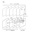
隣接するビューの予め符号化されたテクスチャ情報をシェアするため、視差補償予測(DCP)として知られる技術は、動き補償予測(MCP)の代替の符号化ツールとして、3D−HTM中に含まれている。MCPは、同じビューの予め符号化された画像を用いるピクチャ間(inter-picture)予測、DCPは、同じアクセスユニット中、その他のビューの予め符号化された画像を用いたピクチャ間予測である。図1は、MCPとDCPを組み込んだ3Dビデオ符号化システムの例を示す図である。DCPに用いられるベクトル(110)は視差ベクトル(DV)で、MCPに用いられる動きベクトル(MV)に類似する。図1は、MCPに関連する3個のMV(120、130、および、140)を説明する。さらに、DCPブロックのDVは、さらに、ビュー間リファレンス画像を用いる隣接ブロック、または、時間的配列ブロックから生成する視差ベクトル予測(DVP)候補により予測される。3D−HTMにおいて、Merge/Skipモードのビュー間合併候補を生成するとき、対応するブロックの動き情報が利用可能でない、または、有効出ない場合、ビュー間合併候補がDVにより代替される。 A technique known as Disparity Compensated Prediction (DCP) for sharing pre-encoded texture information of adjacent views is included in 3D-HTM as an alternative coding tool for Motion Compensated Prediction (MCP). Yes. MCP is inter-picture prediction using pre-encoded images of the same view, and DCP is inter-picture prediction using pre-encoded images of other views in the same access unit. FIG. 1 is a diagram illustrating an example of a 3D video encoding system incorporating MCP and DCP. The vector (110) used for DCP is a disparity vector (DV), which is similar to the motion vector (MV) used for MCP. FIG. 1 illustrates three MVs (120, 130, and 140) associated with MCP. Further, the DV of the DCP block is further predicted by a disparity vector prediction (DVP) candidate generated from an adjacent block using an inter-view reference image or a temporal arrangement block. In 3D-HTM, when generating merge / skip mode inter-view merge candidates, if the corresponding block motion information is not available or valid, the inter-view merge candidates are replaced by DV.
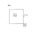
ビュー間残差予測は、3D−HTM中に用いられる別の符号化ツールである。図2に示されるように、隣接するビューの予め符号化された残差情報をシェアするため、現在の予測ブロック(PU)の残留信号は、ビュー間ピクチャ中の対応するブロックの残留信号により予測される。対応するブロックは対応するDVにより設置される。特定のカメラ位置に対応する映像、および、奥行きマップが、ビュー識別子(すなわち、図2中のV0、V1とV2)で示される。同じカメラ位置に属する全映像と奥行きマップは、同じビューId(すなわち、ビュー識別子)に関連する。ビュー識別子が用いられて、アクセスユニット中の符号順序を指定し、エラーが出やすい環境において、紛失したビューを検出する。アクセスユニットは、同一時刻に対応する全映像と奥行きマップを含む。アクセスユニット中、ビューIdが0の映像、および、関連する奥行きマップが存在するとき、まず、ビューIdが1の映像と奥行きマップが符号化される。ビューIdが0(すなわち、図2中のV0)のビューも、ベースビュー、または、ディペンデントビューと称される。ベースビュー映像は、従来のHEVCビデオコーダーを用いて符号化され、別のビューに頼る必要がない。 Inter-view residual prediction is another encoding tool used during 3D-HTM. As shown in FIG. 2, in order to share the pre-encoded residual information of neighboring views, the residual signal of the current prediction block (PU) is predicted by the residual signal of the corresponding block in the inter-view picture. Is done. Corresponding blocks are installed by corresponding DV. An image corresponding to a specific camera position and a depth map are indicated by view identifiers (that is, V0, V1, and V2 in FIG. 2). All videos and depth maps belonging to the same camera position are associated with the same view Id (ie, view identifier). View identifiers are used to specify the code order in the access unit and detect lost views in an error prone environment. The access unit includes all images and depth maps corresponding to the same time. In the access unit, when a video with a view Id of 0 and an associated depth map exist, first, a video with a view Id of 1 and a depth map are encoded. A view whose view Id is 0 (that is, V0 in FIG. 2) is also referred to as a base view or a dependent view. The base view video is encoded using a conventional HEVC video coder and does not need to rely on another view.
図2に示されるように、現在のブロックにとって、動きベクトル予測(MVP)/視差ベクトル予測(DVP)が、ビュー間ピクチャ中のビュー間ブロックから生成される。続いて、ビュー間ピクチャ中のビュー間ブロックが、ビュー間ブロックとして短縮される。生成された候補はビュー間候補で、ビュー間MVP、または、DVPになる。別のビュー中の予め符号化された動き情報に基づいた現在のブロック(たとえば、現在の予測ユニット、PU)の動き情報を符号化する符号化ツールは、ビュー間動きパラメータ予測である。さらに、隣接するビュー中の対応するブロックはビュー間ブロックで、ビュー間ブロックが、現在の画像中の現在のブロックの深さ情報から生成される視差ベクトルを用いて配置される。 As shown in FIG. 2, for the current block, motion vector prediction (MVP) / disparity vector prediction (DVP) is generated from the inter-view block in the inter-view picture. Subsequently, the inter-view block in the inter-view picture is shortened as an inter-view block. The generated candidate is an inter-view candidate and becomes an inter-view MVP or DVP. An encoding tool that encodes motion information for the current block (eg, current prediction unit, PU) based on pre-encoded motion information in another view is inter-view motion parameter prediction. Further, the corresponding block in the adjacent view is an inter-view block, and the inter-view block is arranged using a disparity vector generated from the depth information of the current block in the current image.
ビュー合成予測(VSP)は、異なる視点から、ビデオ信号間のビュー間冗長を除去する技術で、合成シグナルがリファレンスとして用いられ、現在の画像を予測する。3D−HEVCテストモデルにおいて、視差ベクトル予測を生成するいくつかのプロセスがある。その後、生成された視差ベクトルが用いられて、リファレンスビューの深さイメージ中で、深さブロックをフェッチする。フェッチされた深さブロックは、現在の予測ユニット(PU)と同サイズで、その後、現在のPUに後方ラッピング(backward warping)を施すのに用いられる。このほか、ラッピング操作は、サブ−PUレベルの精度、たとえば、8x4、または、4x8ブロックで実行される。最大深度値がサブ−PUブロックに選定され、サブ−PUブロック中の全画素をラッピングするのに用いられる。VSP技術は、テクスチャ画像符号化に適用される。現在の実行において、VSPは新しい合成候補として加えられ、VSP予測の使用を示す。このような方法において、VSPブロックは、いかなる残差もないスキップしたブロックであるか、または、符号化した残差情報を有する合併ブロックである。 View synthesis prediction (VSP) is a technique for removing inter-view redundancy between video signals from different viewpoints, and a synthesized signal is used as a reference to predict the current image. There are several processes for generating disparity vector predictions in the 3D-HEVC test model. Thereafter, the generated disparity vector is used to fetch the depth block in the depth image of the reference view. The fetched depth block is the same size as the current prediction unit (PU) and is then used to perform backward warping on the current PU. In addition, the wrapping operation is performed with sub-PU level accuracy, eg, 8x4 or 4x8 blocks. The maximum depth value is chosen for the sub-PU block and is used to wrap all the pixels in the sub-PU block. VSP technology is applied to texture image coding. In the current run, the VSP is added as a new synthesis candidate, indicating the use of VSP prediction. In such a method, the VSP block is a skipped block without any residual or a merged block with encoded residual information.
図2に示される例は、V0(すなわち、ベースビュー)、V1、および、V2からのビュー符号化順序に対応する。符号化されている現在の画像の現在のブロックはV2である。HTM3.1によると、ビュー間ピクチャが、現在の画像のリファレンス画像リスト中になくても、予め符号化されたビュー中のリファレンスブロックの全MVは、ビュー間候補として見なされる。図2中、フレーム210、220、および、230は、それぞれ、時間t1で、ビューV0、V1とV2からの映像、または、奥行きマップに対応する。ブロック232は、現在のビュー中の現在のブロックであり、ブロック212と222は、それぞれ、V0とV1中の現在のブロックである。VO中の現在のブロック212において、視差ベクトル(216)が用いられて、ビュー間配列ブロック(214)を配置する。同様に、V1中の現在のブロック222において、視差ベクトル(226)が用いられて、ビュー間配列ブロック(224)を配置する。HTM3.1によると、任意の符号化されたビューからのビュー間配列ブロックに関連する動きベクトル、または、視差ベクトルは、ビュー間候補中に含まれる。よって、ビュー間候補の数量は相当大きく、これは、さらに多くの処理時間とストレージ空間が必要になる。処理時間、および/または、ストレージ要求を減少させ、BD率やその他の性能測定方面で、システムパフォーマンスに非常に注目すべき衝撃を与えることがない方法を開発することが必要である。
The example shown in FIG. 2 corresponds to the view coding order from V0 (ie, base view), V1, and V2. The current block of the current image being encoded is V2. According to HTM 3.1, even if the inter-view picture is not in the reference image list of the current image, all MVs of the reference block in the pre-encoded view are considered as inter-view candidates. In FIG. 2, frames 210, 220, and 230 respectively correspond to images from views V0, V1, and V2 or a depth map at time t1.
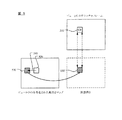
3DV−HTMにおいて、視差ベクトルは、InterモードのDVP候補、または、Merge/Skipモードの合併候補として用いられる。生成された視差ベクトルは、また、ビュー間動き予測とビュー間残差予測のオフセットベクトルとして用いられる。オフセットベクトルとして用いられるとき、図3に示されるように、DVが、空間的、または、時間的隣接ブロックから派生する。所定の順序にしたがって、複数の空間的、および、時間的隣接ブロックが決定され、空間的、および、時間的隣接ブロックのDVの可用性が確認される。隣接(空間的、および、時間的)ブロックに基づいたDV導出のこの符号化ツールは、隣接ブロックDV(NBDV)と称される。図3Aに示されるように、空間的隣接ブロック集合は、現在のブロックの左下角位置(すなわち、A0)、現在のブロックの左下側位置(すなわち、A1)、現在のブロックの左上角位置(すなわち、B2)、現在のブロックの右上角位置(すなわち、B0)、および、現在のブロックの右上側の位置(すなわち、B1)を含む。図3Bに示されるように、時間的隣接ブロック集合は、時間的リファレンス画像中、現在のブロックの中心位置(すなわち、BCTR)、および、現在のブロックの右下角位置(すなわち、RB)を含む。中央位置を除いて、時間的リファレンス画像中の現在のブロック内の別の位置(たとえば、右下のブロック)も用いられる。つまり、現在のブロックと配置される任意のブロックは、時間的ブロック集合中に含まれる。一旦、ブロックがDVを有すると識別されると、確認プロセスが終了する。図3A中の空間的隣接ブロックの例の検索順序は、(A1、B1、B0、A0、B2)である。図3B中の時間的隣接ブロックの例の検索順序は(BR,BCTR)である。空間的、および、時間的隣接ブロックは、HEVC中のAMVPとMergeモードの空間的、および、時間的隣接ブロックと同じである。 In 3DV-HTM, the disparity vector is used as a DVP candidate in the Inter mode or a merge candidate in the Merge / Skip mode. The generated disparity vector is also used as an offset vector for inter-view motion prediction and inter-view residual prediction. When used as an offset vector, DV is derived from spatially or temporally adjacent blocks, as shown in FIG. In accordance with a predetermined order, a plurality of spatial and temporal neighboring blocks are determined and the DV availability of the spatial and temporal neighboring blocks is confirmed. This coding tool for DV derivation based on neighboring (spatial and temporal ) blocks is called Neighboring Block DV (NBDV). As shown in FIG. 3A, the spatially adjacent block set includes the lower left corner position of the current block (ie, A0), the lower left position of the current block (ie, A1), and the upper left corner position of the current block (ie, A1). , B2), the upper right corner position of the current block (ie, B0), and the upper right position of the current block (ie, B1). As shown in FIG. 3B, the temporal neighbor block set includes the current block center location (ie, BCTR) and the current block lower right corner location (ie, RB) in the temporal reference image. Other than the center position, another position within the current block in the temporal reference image (eg, the lower right block) is also used. That is, an arbitrary block arranged with the current block is included in the temporal block set. Once the block is identified as having DV, the verification process ends. The search order of the example of spatially adjacent blocks in FIG. 3A is (A1, B1, B0, A0, B2). The search order of the example of temporally adjacent blocks in FIG. 3B is (BR, BCTR). Spatial and temporal neighboring blocks spatially the AMVP and Merge mode in HEVC, and is the same as the temporal neighboring blocks.
DCP符号化ブロックが、隣接ブロック集合(すなわち、図3Aと図3Bに示されるように、空間的、および、時間的隣接ブロック)で見つからない場合、視差情報は、別の符号化ツール(DV−MCP)から得られる。この場合は、隣接ブロックがMCP符号化ブロックで、且つ、その動きが、ビュー間動き予測により予測されるとき、図4に示されるように、ビュー間動き予測に用いられる視差ベクトルは、現在とビュー間リファレンス画像間の動き通信を示す。この種の動きベクトルは、ビュー間予測動きベクトルと称され、ブロックはDV−MCPブロックと称される。図4は、DV−MCPブロックの例を示す図で、DV−MCPブロック(410)の動き情報が、ビュー間リファレンス画像中の対応するブロック(420)から予測される。対応するブロック(420)の位置が視差ベクトル(430)により指定される。DV−MCPブロック中で用いられる視差ベクトルは、現在とビュー間リファレンス画像間の動き通信を示す。対応するブロック(420)の動き情報(422)が用いられて、現在のビュー中の現在のブロック(410)の動き情報(412)を予測する。 If a DCP coded block is not found in the neighboring block set (ie, spatial and temporal neighboring blocks as shown in FIGS. 3A and 3B), the disparity information is stored in another coding tool (DV− MCP). In this case, when the adjacent block is an MCP encoded block and its motion is predicted by inter-view motion prediction, as shown in FIG. 4, the disparity vector used for inter-view motion prediction is Fig. 4 illustrates motion communication between inter-view reference images. This type of motion vector is referred to as an inter-view prediction motion vector, and the block is referred to as a DV-MCP block. FIG. 4 is a diagram illustrating an example of the DV-MCP block, and motion information of the DV-MCP block (410) is predicted from a corresponding block (420) in the inter-view reference image. The position of the corresponding block (420) is specified by the disparity vector (430). The disparity vector used in the DV-MCP block indicates motion communication between the current and inter-view reference images. The motion information (422) of the corresponding block (420) is used to predict the motion information (412) of the current block (410) in the current view.
MCPブロックが、符号化されるDV−MCPであるかを示し、ビュー間動きパラメータ予測の視差ベクトルを保存するため、二つの変数が用いられて、各ブロックの動きベクトル情報を表す。dvMcpFlag、および、dvMcpDisparityである。 In order to indicate whether the MCP block is a DV-MCP to be encoded and to store a disparity vector for inter-view motion parameter prediction, two variables are used to represent motion vector information of each block. dvMcpFlag and dvMcpDisparity.
dvMcpFlagが1のとき、dvMCP視差は、視差ベクトルがビュー間動きパラメータ予測に用いられることを示すように設定される。AMVPとMerge候補リストの構成プロセスにおいて、候補がビュー間動きパラメータ予測により生成される場合、候補のdvMcpFlagは、1に設定され、そうでない場合は、0に設定される。DV−MCPブロックからの視差ベクトルは以下の順序で用いられる:A0、A1、B0、B1、B2、Col(すなわち、配列ブロックBCTRまたはRB)。 When dvMcpFlag is 1, the dvMCP disparity is set to indicate that the disparity vector is used for inter-view motion parameter prediction. In the process of constructing AMVP and Merge candidate lists, if a candidate is generated by inter-view motion parameter prediction, the candidate dvMcpFlag is set to 1, otherwise it is set to 0. The disparity vectors from the DV-MCP block are used in the following order: A0, A1, B0, B1, B2, Col (ie, array block BCTR or RB).
奥行きマップから、さらに精密な視差ベクトルを抽出することにより、NBDVを増強する方法が、現在の3D−HEVCに用いられている。まず、同じアクセスユニット中で符号化された奥行きマップからの深さブロックが検索され、現在のブロックの仮想深さとして用いられる。DV導出のためのこの符号化ツールは、深さ配向NBDV(DoNBDV)と称される。共同テスト条件下で、ビュー1とビュー2中のテクスチャを符号化する間、ビュー0の奥行きマップはすでに利用可能である。ビュー1とビュー2中のテクスチャの符号化は、ビュー0の奥行きマップから恩恵を受けることができる。図5で示されるように、推定された視差ベクトルは、仮想深さから引き出される。全体の流れは以下のようである:
1.現在の3D−HTM中のNBDVである推定された視差ベクトルを用いて、符号化されたテクスチャビュー中、対応するブロックを配置する。
2.現在のブロック(符号化ユニット)の符号化されたビュー中の配列深さを、仮想深さとして用いる。
3.前のステップで検索された仮想深さ中の最大値から、ビュー間動き予測の視差ベクトルを抽出する。
A method of enhancing NBDV by extracting a more precise disparity vector from a depth map is used in current 3D-HEVC. First, the depth block from the depth map encoded in the same access unit is retrieved and used as the virtual depth of the current block. This encoding tool for DV derivation is referred to as depth oriented NBDV (DoNBDV). The
1. The estimated disparity vector, which is the NBDV in the current 3D-HTM, is used to place the corresponding block in the encoded texture view.
2. The array depth in the encoded view of the current block (encoding unit) is used as the virtual depth.
3. A disparity vector for inter-view motion prediction is extracted from the maximum value in the virtual depth searched in the previous step.
図5で説明される例において、ビュー0中の符号化された奥行きマップが用いられて、DVを符号化されるビュー1中のテクスチャフレームに派生させる。ビュー0中の推定された視差ベクトル(540)、および、符号化された奥行きマップの現在のブロックの位置(520)にしたがって、符号化されたD0中の対応する深さブロック(530)が、現在のブロック(CB,510)に検索される。検索されたブロック(530)は、その後、現在のブロックの仮想深さブロック(530’)として用いられ、DVを生成する。仮想深さブロック(530’)中の最大値が用いられて、ビュー間動き予測の視差ベクトルを取り出す。
In the example illustrated in FIG. 5, the encoded depth map in
現在の3D−AVC(3D video coding based on Advanced video coding (AVC))において、視差ベクトル(DV)が、視差補償予測(DCP)、予測DVに用いられると共に、ビュー間対応ブロックに、ビュー間候補を生成するよう指示する。 In the current 3D-AVC (3D video coding based on Advanced video coding (AVC)), the disparity vector (DV) is used for the disparity compensation prediction (DCP) and the prediction DV, and the inter-view candidate is included in the inter-view corresponding block. To generate
リファレンスビューの予め符号化されたテクスチャ情報をシェアするため、視差補償予測(DCP)のコンセプトが代替方式として、動き補償予測(MCP)に追加されている。MCPは、異なるアクセスユニット中の同じビューのすでに符号化された画像を用いるピクチャ間予測で、DCPは、同じアクセスユニット中の別のビューのすでに符号化された画像を用いるピクチャ間予測である。DCPに用いられるベクトルは視差ベクトル(DV)で、MCPに用いられる動きベクトル(MV)に類似する。 In order to share the pre-encoded texture information of the reference view, the concept of disparity compensation prediction (DCP) is added to motion compensation prediction (MCP) as an alternative method. MCP is inter-picture prediction using already coded images of the same view in different access units, and DCP is inter-picture prediction using already coded images of another view in the same access unit. The vector used for DCP is a disparity vector (DV), which is similar to the motion vector (MV) used for MCP.
Interモードにおいて、方向分離動きベクトル予測は、3D−AVC中に用いられる別の符号化ツールである。方向分離動きベクトル予測は、時間的、および、ビュー間動きベクトル予測から構成される。ターゲットリファレンス画像が時間的予測画像である場合、現在のブロックCb、図6A中のたとえば、A、B、および、C周辺の隣接するブロックの時間的動きベクトルが、動きベクトル予測の導出に用いられる。時間的動きベクトルが利用可能でない場合、ビュー間動きベクトルが用いられる。ビュー間動きベクトルが、深さから変換されるDVで示される対応するブロックから生成される。その後、動きベクトル予測が、隣接するブロックA、B、および、Cの動きベクトルの中央値として生成される。Cが利用可能でないとき、ブロックDだけが用いられる。 In Inter mode, direction-separated motion vector prediction is another coding tool used during 3D-AVC. Direction-separated motion vector prediction consists of temporal and inter-view motion vector prediction. If the target reference image is a temporal prediction image, the temporal motion vectors of the current block Cb, eg, adjacent blocks around A, B, and C in FIG. 6A are used to derive motion vector prediction. . If temporal motion vectors are not available, inter-view motion vectors are used. Inter-view motion vectors are generated from corresponding blocks indicated by DV that are transformed from depth. A motion vector prediction is then generated as the median of the motion vectors of adjacent blocks A, B, and C. When C is not available, only block D is used.
それどころか、ターゲットリファレンス画像が、ビュー間予測画像である場合、隣接ブロックのビュー間動きベクトルがビュー間予測に用いられる。ビュー間動きベクトルが利用可能でない場合、関連する深さブロック中の4個のコーナー深さサンプルの最大深度値から生成される視差ベクトルが用いられる。その後、動きベクトル予測が、隣接するブロックA、B、および、Cのビュー間動きベクトルの中央値として生成される。 On the contrary, when the target reference image is an inter-view prediction image, the inter-view motion vector of the adjacent block is used for inter-view prediction. If no inter-view motion vector is available, the disparity vector generated from the maximum depth value of the four corner depth samples in the associated depth block is used. A motion vector prediction is then generated as the median of the inter-view motion vectors of adjacent blocks A, B, and C.
ターゲットリファレンス画像がビュー間予測画像であるとき、隣接ブロックのビュー間動きベクトルが用いられて、ビュー間動きベクトル予測を生成する。図6Bのブロック610において、対応するブロックのテクスチャデータに基づいて、空間的隣接ブロックのビュー間動きベクトルが生成される。現在のブロックCbに関連する奥行きマップも、ブロック660中に提供される。ブロック620中で、ブロックA、B、および、Cのビュー間動きベクトルの可用性が確認される。ブロック630に示されるように、ビュー間動きベクトルが利用可能でない場合、現在のブロックの視差ベクトルが用いられて、利用可能でないビュー間動きベクトルを代替する。ブロック670に示されるように、視差ベクトルが、関連する深さブロックの最大深度値から生成される。ブロックA、B、および、Cのビュー間動きベクトルの中央値が、ビュー間動きベクトル予測として用いられる。ブロック640に示されるように、従来のMVP工程において、最終MVPは、ビュー間MVP、または、時間的MVPの動きベクトルの中央値に基づいて生成される。ブロック650に示されるように、動きベクトル予測に基づいて、動きベクトル符号化が実行される。
When the target reference image is an inter-view prediction image, the inter-view motion vector of the adjacent block is used to generate an inter-view motion vector prediction. In
Skip/Directモードの優先ベースのMVP候補導出は、3D−AVCの別の符号化ツールである。Skip/Directモードにおいて、MVP候補は、所定の導出順序に基づいて生成される。図7に示されるように、隣接ブロックA、B、および、C(Cが利用可能ではないとき、Dだけが用いられる)から、ビュー間候補、および、3個の空間的候補の中央値が生成される。 Skip / Direct mode priority-based MVP candidate derivation is another 3D-AVC coding tool. In the Skip / Direct mode, MVP candidates are generated based on a predetermined derivation order. As shown in FIG. 7, from neighboring blocks A, B, and C (only D is used when C is not available), the median of inter-view candidates and three spatial candidates is Generated.
ビュー間MV候補導出も図7で示される。ディペンデントビューの現在のブロック(710)の中央点(712)、および、その視差ベクトルが用いられて、ベースビュー、または、リファレンスビュー中の対応点を探す。その後、ベースビュー中の対応点を含むブロックのMVが、現在のブロックのビュー間候補として用いられる。視差ベクトルは、隣接ブロック(A、B、および、C/D)、および、中央点の深度値両方から生成される。特に、一個の隣接ブロックだけが視差ベクトル(DV)を有する場合、DVは視差として用いられる。そうでなければ、DVは、その後、隣接するブロックA、B、および、CのDV(720)の中央値として生成される。DVが利用可能でない場合、深さから変換されたDVが代わりに用いられる。生成されたDVは、リファレンス画像(730)中の対応するブロック(740)を配置するのに用いられる。 Inter-view MV candidate derivation is also shown in FIG. The center point (712) of the current block (710) of the dependent view and its disparity vector are used to find the corresponding point in the base view or reference view. Thereafter, the MV of the block including the corresponding point in the base view is used as an inter-view candidate of the current block. The disparity vector is generated from both adjacent blocks (A, B, and C / D) and the midpoint depth value. In particular, when only one adjacent block has a disparity vector (DV), DV is used as disparity. Otherwise, the DV is then generated as the median value of the DV (720) of adjacent blocks A, B, and C. If DV is not available, DV converted from depth is used instead. The generated DV is used to place the corresponding block (740) in the reference image (730).
上述のように、3D−HEVCと3D−AVC両方の3Dビデオ符号化において、DV導出は重大な意味を持つ。3Dシーケンスをテストする条件が修正され、且つ、ビュー間に垂直偏移がないことを考慮すると、ある符号化ツールは、ビュー間データアクセスの垂直方向成分がないDVだけを使用する。しかし、入力データが修正されない時、DVの垂直方向成分で、別のビュー中の正確な対応ブロックを示す必要がある。 As mentioned above, DV derivation is significant in 3D video coding for both 3D-HEVC and 3D-AVC. Considering that the conditions for testing 3D sequences have been modified and that there are no vertical shifts between views, some encoding tools only use DVs that have no vertical component of inter-view data access. However, when the input data is not modified, the vertical component of DV needs to indicate the exact corresponding block in another view.
三次元のビデオ符号化、または、復号化の方法と装置が開示される。 A three-dimensional video encoding or decoding method and apparatus is disclosed.
一実施形態において、現在のテクスチャブロックの生成されたDV(視差ベクトル)が決定され、且つ、DV制約が、生成されたDVに適用され、または、適用されず、最後に生成されたDVを獲得する。その後、選択された符号化ツールの少なくともひとつを用いて、ビュー間予測符号化、または、復号化が入力データに適用され、最後に生成された同じDVが選択された符号化ツール全てにより用いられ、選択された符号化ツールは、ビュー間残差予測、ビュー合成予測、および、ビュー間動きパラメータ予測を有する。最後に生成されたDVが用いられて、ビュー間残差予測のビュー間ピクチャ中のリファレンス残差ブロックを配置し、最後に生成されたDV、または、最後に生成されたDVにより配置されるリファレンスブロックに関連する、関連する動きベクトルは、ビュー間動きパラメータ予測のビュー間動きベクトル予測として用いられ、最後に生成されたDVが用いられて、ビュー合成予測のビュー間深さ画像中のリファレンス深さブロックを配置する。符号化ツールはDCP(視差補償予測)を除外する。DV制約表示が用いられて、DV制約が、生成されたDVに適用されるかどうか判断し、符号化プロファイルにしたがって、DV制約表示が決定される。 In one embodiment, the generated DV (disparity vector) of the current texture block is determined and a DV constraint is applied to the generated DV or not applied to obtain the last generated DV. To do. Then, using at least one of the selected encoding tools, inter-view predictive encoding or decoding is applied to the input data and the last generated same DV is used by all selected encoding tools. The selected encoding tool has inter-view residual prediction, view synthesis prediction, and inter-view motion parameter prediction. The last generated DV is used to place the reference residual block in the inter-view picture of the inter-view residual prediction, and the last generated DV or the reference arranged by the last generated DV that relate to the block, associated motion vector is used as inter-view motion vector prediction of-view motion parameter prediction, finally is used generated DV, reference in-view depth image view synthesis prediction Place a depth block. The encoding tool excludes DCP (disparity compensation prediction). The DV constraint indication is used to determine whether the DV constraint is applied to the generated DV, and the DV constraint indication is determined according to the encoding profile.
一実施形態において、DV制約が第一プロファイルに適用されるとき、選択された符号化ツールはDCP(視差補償予測)を除外し、DCPに用いられる生成されたDVの垂直方向成分が、小範囲で設定され、選択された符号化ツールに生成されたDVの垂直方向成分がゼロに設定される。VPS(ビデオパラメータセット)、PPS(picture parameter set)、SPS(sequence parameter set)、スライスヘッダー、シーケンスレベル、ビューレベル、ピクチャレベル、スライスレベル、LCU(Coding Tree Unit;CTUとも称される)レベル、CUレベル、または、PUレベルで、構文要素を用いて、DV制約表示がシグナリングされる。DV制約は、最後に生成されたDVの垂直方向成分、または、水平成分をゼロに設定するか、または、小範囲に設定する。 In one embodiment, when a DV constraint is applied to the first profile, the selected encoding tool excludes DCP (Parallax Compensated Prediction) and the vertical component of the generated DV used for DCP is a small range. And the vertical component of the DV generated for the selected encoding tool is set to zero. VPS (video parameter set), PPS (picture parameter set), SPS (sequence parameter set), slice header, sequence level, view level, picture level, slice level, LCU (Coding Tree Unit; also called CTU) level, A DV constraint indication is signaled using syntax elements at the CU level or at the PU level. In the DV constraint, the vertical component or horizontal component of the last generated DV is set to zero or set to a small range.
本発明の一態様は、ビュー間残差予測の補間プロセスに取り組む。最後に生成されたDVがサブ−サンプル位置を指し示し、DV制約が適用されるとき、1Dフィルター(一次元フィルター)を用いて、リファレンスビューの残差サンプルを補間することにより、ビュー間残差予測の残差予測信号が生成される。しかし、DV制約が適用されない場合、2Dフィルター(二次元フィルター)を用いて、リファレンスビューの残差サンプルを補間することにより、ビュー間残差予測の残差予測信号が生成される。DoNBDV(深さ配向隣接ブロック視差ベクトル)にとって、および、最後に生成されたDVがサブ−サンプル位置を指し示し、DV制約が適用されるとき、1Dフィルター(一次元フィルター)を用いて、リファレンスビューの残差サンプルを補間することにより、DoNBDVの深さ信号が生成される。しかし、DV制約が適用されないとき、2Dフィルター(二次元フィルター)を用いて、リファレンスビューの残差サンプルを補間することにより、DoNBDVの深さ信号が生成される。2Dフィルターは、最後に生成されたDVをラウンディングすることにより生成されるラウンディングDVにより指し示される第一整数深さサンプルの第一値を整数値にする2Dラウンディングフィルターである。DV制約インジケーターが、DV制約が有効であることを示すとき、DoNBDVにより派生したDVの垂直方向成分がゼロに設定される。 One aspect of the invention addresses the interpolation process for inter-view residual prediction. When the last generated DV points to the sub-sample location and DV constraints are applied, inter-view residual prediction is performed by interpolating the reference view residual samples using a 1D filter (one-dimensional filter). Residual prediction signals are generated. However, when the DV constraint is not applied, a residual prediction signal for inter-view residual prediction is generated by interpolating the residual sample of the reference view using a 2D filter (two-dimensional filter). For DoNBDV (depth oriented contiguous block disparity vector) and when the last generated DV points to a sub-sample position and DV constraints are applied, a 1D filter (one-dimensional filter) is used to By interpolating the residual samples, a DoNBDV depth signal is generated. However, when the DV constraint is not applied, a DoNBDV depth signal is generated by interpolating the residual samples of the reference view using a 2D filter (two-dimensional filter). The 2D filter is a 2D rounding filter that sets the first value of the first integer depth sample indicated by the rounding DV generated by rounding the last generated DV to an integer value. When the DV constraint indicator indicates that the DV constraint is valid, the vertical component of the DV derived by DoNBDV is set to zero.
上述のように、DVは、3D−HEVC、および、3D−AVC両方の3Dビデオ符号化において非常に重要な意味を持つ。本発明の実施形態において、視差ベクトル(DV)に、条件付きで、制約を適用する、または、除去する方法が開示される。さらに、本方法は、選択的に、3D、および、多視点ビデオ符号化システムにおいて、DVに適用される。 As mentioned above, DV has very important meaning in 3D video coding of both 3D-HEVC and 3D-AVC. In an embodiment of the present invention, a method for conditionally applying or removing constraints on a disparity vector (DV) is disclosed. Furthermore, the method is optionally applied to DV in 3D and multi-view video coding systems.
現有の3D−HEVCと3D−AVCにおいて、いくつかの符号化ツール中、制約が適用されて、垂直方向DV成分を強制的にゼロにする。しかし、別の符号化ツールにおいて、制約は垂直方向DV成分に適用されない。本発明の一実施形態において、視差補償予測(DCP)に用いられるDVを除いて、制約が、統一方式で、全符号化ツールのDVに適用される、または、除去される。つまり、DCPに用いられるもの以外の全DVの垂直方向成分が強制的にゼロ(あるいは、元のDVよりさらに小さい範囲内)になる、または、非ゼロ値を有することが容認される。制約はDVの水平成分に適用してもよい。さらに、制約は、選択された符号化ツールに用いられるDVだけに適用される。別の符号化ツールに用いられるDVは何の制約も受けない。あるいは、異なる制約が、別の符号化ツールに用いられるDVに適用される。 In existing 3D-HEVC and 3D-AVC, constraints are applied in some encoding tools to force the vertical DV component to zero. However, in another encoding tool, the constraint is not applied to the vertical DV component. In one embodiment of the present invention, except for DV used for disparity compensated prediction (DCP), constraints are applied to or removed from DV of all coding tools in a unified manner. That is, it is accepted that the vertical components of all DVs other than those used for DCP are forced to zero (or in a range smaller than the original DV) or have non-zero values. The constraints may apply to the horizontal component of DV. Furthermore, the constraints apply only to DVs used for the selected encoding tool. DV used in other encoding tools is not subject to any restrictions. Alternatively, different constraints apply to DV used for another encoding tool.
現有の3D−HEVCと3D−AVCにおいて、DV−MCPブロックから生成されるDVの水平成分だけが保存され、垂直方向成分が破棄される。制約がDVで除去されるとき、DV−MCPブロックから生成されるDVの垂直方法成分が非ゼロになる。この場合は、生成されるDVの垂直方向成分が保存される。DVの条件付き制約が、DV−MCPブロックから派生するDVに適用される。同様に、DV上の条件付き制約が、別の3Dビデオ符号化ツールに適用される。 In the existing 3D-HEVC and 3D-AVC, only the horizontal component of DV generated from the DV-MCP block is stored, and the vertical component is discarded. When the constraint is removed at DV, the vertical method component of DV generated from the DV-MCP block becomes non-zero. In this case, the vertical component of the generated DV is stored. DV conditional constraints apply to DVs derived from DV-MCP blocks. Similarly, conditional constraints on DV apply to other 3D video encoding tools.
上述の条件付き制約は、DVの垂直(または、水平)成分を、強制的にゼロ、または、MからNの所定範囲内で小さい値にする。特定の実施方式において、DVの垂直(水平)成分をゼロに設定する代わりに、DVの水平(または、垂直)成分だけが用いられる。よって、いくつかのメモリバッファが省略できる。さらに、一追加構文要素が、PPS(picture parameter set)、SPS(sequence parameter set)、スライスヘッダー、シーケンスレベル、ビューレベル、ピクチャレベル、スライスレベル、LCUレベル、CUレベル、PUレベル、または、その他のレベルでシグナリングされて、どの成分(垂直、または、水平)が制約を受けるか示す。 The conditional constraints described above force the vertical (or horizontal) component of DV to zero or a small value within a predetermined range from M to N. In certain implementations, instead of setting the vertical (horizontal) component of DV to zero, only the horizontal (or vertical) component of DV is used. Therefore, some memory buffers can be omitted. Furthermore, one additional syntax element is PPS (picture parameter set), SPS (sequence parameter set), slice header, sequence level, view level, picture level, slice level, LCU level, CU level, PU level, or other Signaled at the level to indicate which components (vertical or horizontal) are constrained.
DVの条件付き制約は、以下の条件に基づく:
1.カメラが水平に配列されるとき。
2.入力多視点ビデオが修正されるとき。
3.ビュー間に垂直視差が存在しないとき。
4.カメラの光軸が水平で、ビューが修正されて、垂直視差が存在しないとき。
5.カメラが垂直に配列されるとき。
6.ビュー間に、水平視差が存在しないとき。
7.カメラの光軸が垂直で、ビューが修正されて、水平視差が存在しないとき。
DV conditional constraints are based on the following conditions:
1. When the cameras are arranged horizontally.
2. When the input multi-view video is modified.
3. When there is no vertical parallax between views.
4). When the optical axis of the camera is horizontal, the view is modified, and there is no vertical parallax.
5. When the cameras are arranged vertically.
6). When there is no horizontal parallax between views.
7). When the optical axis of the camera is vertical, the view is modified and there is no horizontal parallax.
追加構文が、VPS(ビデオパラメータセット)、PPS、SPS、スライスヘッダー、シーケンスレベル、ビューレベル、ピクチャレベル、スライスレベル、LCUレベル、CUレベル、PUレベル、または、その他のレベルでシグナリングされて、制約がDVに適用されるかどうか示す。プロファイル依存スキームが別の実施形態に用いられて、制約が生成されたDVに適用されるかどうか示す。符号化システムにおいて、通常、符号化プロファイルが定義され、異なるアプリケーションの符号化システムを設定する。たとえば、メインプロファイルがコモンアプリケーションに用いられる。 Additional syntax is signaled at VPS (Video Parameter Set), PPS, SPS, Slice Header, Sequence Level, View Level, Picture Level, Slice Level, LCU Level, CU Level, PU Level, or Other Levels and Constraints Indicates whether this applies to DV. A profile dependency scheme is used in another embodiment to indicate whether a constraint applies to the generated DV. In an encoding system, an encoding profile is usually defined to set up an encoding system for different applications. For example, the main profile is used for common applications.
単独で、または、組み合わせて、上述の例の条件が用いられる。たとえば、構文要素がシグナリングされて、DCPに用いられるDVの垂直方向成分が小さい範囲内にあるか、および、DCPに用いられるもの以外の全DVの垂直成分が強制的にゼロになるかを示す。別の例において、構文がシグナリングされて、DCPに用いられるもの以外の全DVの垂直方向成分が強制的にゼロになるか示す。この場合は、DCPに用いられるDVの垂直方向成分が縮小範囲に制限される、または、デフォルト設計に応じず、追加構文を送信しない。さらに別の例において、構文がシグナリングされて、DCPに用いられるDVの垂直方向成分が縮小範囲内にあるか示す。DCPに用いられる以外の全DVの垂直方向成分は、ゼロ、または、デフォルト設計に基づいて、非ゼロになり、追加構文を送信しない。さらに別の例において、追加構文がシグナリングされて、DCPに用いられるDVの垂直方向成分が縮小範囲内にあるか示す。さらに、追加構文がシグナリングされて、DCPに用いられるもの以外の全DVの垂直方向成分が強制的にゼロになるか示す。さらに別の例において、特定のプロファイルの選択に対し、DCPに用いられるDVの垂直方向成分は縮小範囲内にあり、且つ、DCPに用いられるもの以外の全DVの垂直方向成分が強制的にゼロになる。 The conditions of the above examples are used alone or in combination. For example, a syntax element is signaled to indicate whether the vertical component of the DV used for DCP is within a small range, and whether the vertical components of all DV other than those used for DCP are forced to zero . In another example, syntax is signaled to indicate whether the vertical component of all DVs other than those used for DCP is forced to zero. In this case, the vertical component of the DV used for DCP is limited to the reduced range, or does not comply with the default design and does not send additional syntax. In yet another example, the syntax is signaled to indicate whether the vertical component of the DV used for DCP is within the reduced range. The vertical component of all DVs other than those used for DCP will be zero or non-zero based on the default design and will not send additional syntax. In yet another example, additional syntax is signaled to indicate whether the vertical component of the DV used for DCP is within the reduced range. In addition, additional syntax is signaled to indicate whether the vertical components of all DVs other than those used for DCP are forced to zero. In yet another example, for the selection of a particular profile, the vertical component of the DV used for DCP is within the reduced range, and the vertical component of all DVs other than those used for DCP is forced to zero. become.
本発明の別の実施形態において、条件付き制約が、3D、および、多視点ビデオ符号化システム中の適応符号化に適用される。DV制約は、特定範囲内で生成されたDVの制限されたx−成分(すなわち、水平成分)、y−成分(すなわち、垂直方向成分)、または、両方に対応する。 In another embodiment of the invention, conditional constraints are applied to adaptive coding in 3D and multi-view video coding systems. A DV constraint corresponds to a limited x-component (ie, horizontal component), y-component (ie, vertical component), or both, of DV generated within a particular range.
本発明の一態様は、視差ベクトルがサブ−サンプル位置を指し示すとき、ビュー間残差予測のDVの条件付き制約のDV導出に取り組む。この場合は、1D(一次元)フィルターを用いて、リファレンスビューの残差サンプルを補間することにより、残差予測信号が得られる。以下のリストから1Dフィルターが選択される:
1.1D(一次元)線形フィルター、
2.二つの最も近い整数残差サンプルを平均する1D平均フィルター、
3.二つのもっとも近い整数残差サンプルの最小値を選択する1D最小フィルター、
4.二つのもっとも近い整数残差サンプルの最大値を選択する1D最大フィルター、
5.ラウンディングDVにより指し示される整数残差サンプルの値を用いる 1Dラウンディングフィルター、および、
6.短縮型DVにより指し示される整数残差サンプルの値を用いる1D短縮型(truncating)フィルター。
One aspect of the present invention addresses DV derivation of conditional constraints on DV for inter-view residual prediction when disparity vectors point to sub-sample positions. In this case, a residual prediction signal is obtained by interpolating the residual samples of the reference view using a 1D (one-dimensional) filter. A 1D filter is selected from the following list:
1.1D (one-dimensional) linear filter,
2. A 1D average filter that averages the two nearest integer residual samples;
3. A 1D minimum filter that selects the minimum of the two nearest integer residual samples;
4). A 1D maximum filter that selects the maximum of the two nearest integer residual samples,
5. A 1D rounding filter that uses the value of the integer residual sample pointed to by the rounding DV, and
6). A 1D truncating filter that uses the value of the integer residual sample pointed to by the truncated DV.
ビュー間残差予測のDV制約が無効である場合、視差ベクトルがサブ−サンプル位置を指し示す場合、2D(二次元)フィルターを用いて、リファレンスビューの残差サンプルを補間することにより、残差予測信号が得られる。2Dフィルターは以下のリストから選択される:
1.2D双線形フィルター、
2.4つの最も近い整数残差サンプルを平均する2D平均フィルター、
3.4つの最も近い整数残差サンプルの最小値を選択する2D最小フィルター、
4.4つの最も近い整数残差サンプルの最大値を選択する2D最大フィルター、
5.4つの最も近い整数残差サンプルの中央値を用いる2D中央値フィルター、
6.ラウンディングDVにより指し示される整数残差サンプルの値を用いる2Dラウンディングフィルター、および、
7.短縮型DVにより指し示される整数残差サンプルの値を用いる2D短縮型フィルター。
If the DV constraint for inter-view residual prediction is invalid, or if the disparity vector points to a sub-sample position, residual prediction is performed by interpolating the reference view residual samples using a 2D (two-dimensional) filter. A signal is obtained. The 2D filter is selected from the following list:
1.2D bilinear filter,
2. a 2D average filter that averages the four nearest integer residual samples;
3. a 2D minimum filter that selects the minimum of the four nearest integer residual samples;
4. A 2D maximum filter that selects the maximum of the four nearest integer residual samples;
5. A 2D median filter that uses the median of the four nearest integer residual samples;
6). A 2D rounding filter that uses the value of the integer residual sample pointed to by the rounding DV, and
7). A 2D shortened filter that uses the value of the integer residual sample pointed to by the shortened DV.
上述のリストは、イメージ処理に用いられる従来の1Dフィルターを示す。しかし、リストは、包括的リストの方式ではない。本発明の別の態様は、視差ベクトルがサブ−サンプル位置を指し示すとき、深さ配向の隣接ブロックの視差ベクトル(DoNBDV)の条件付き制約のDV導出に取り組む。この場合は、1D(一次元)フィルターを用いて、リファレンスビューの深さサンプルを補間することにより、リファレンスビュー中の深さ信号が得られる。1Dフィルターが同じ1Dフィルターリストから選択され、有効なDVの条件付き制約を有するビュー間残差予測に用いられる。 The above list shows a conventional 1D filter used for image processing. However, lists are not a comprehensive list scheme. Another aspect of the present invention addresses DV derivation of conditional constraints of disparity vectors (DoNBDV) of adjacent blocks in depth orientation when the disparity vector points to a sub-sample location. In this case, the depth signal in the reference view is obtained by interpolating the depth sample of the reference view using a 1D (one-dimensional) filter. A 1D filter is selected from the same 1D filter list and used for inter-view residual prediction with valid DV conditional constraints.
DoNBDVのDV制約が無効であるとき、視差ベクトルがサブ−サンプル位置を指し示す場合、2D(二次元)フィルターを用いて、リファレンスビューの深さサンプルを補間することにより、リファレンスビュー中の深さ信号が得られる。2Dフィルターが、同一の2Dフィルターリストが選択され、無効のDVの条件付き制約を有するビュー間残差予測に用いられる。一実施形態において、補間に用いられる2Dフィルターは、最後に生成されたDVをラウンディングすることにより生成されるラウンディングDVに指し示される第一整数深さサンプルの第一値を整数値にする2Dラウンディングフィルターである。 Depth signal in the reference view by interpolating the depth sample of the reference view using a 2D (two-dimensional) filter when the disparity vector points to the sub-sample position when the DVNBDV DV constraint is disabled Is obtained. A 2D filter is used for inter-view residual prediction with the same 2D filter list selected and an invalid DV conditional constraint. In one embodiment, the 2D filter used for interpolation makes the first value of the first integer depth sample pointed to the rounding DV generated by rounding the last generated DV an integer value. 2D rounding filter.
本発明の一実施形態を組み込んだシステムのパフォーマンスと従来のシステムを比較する。コモンテスト条件(CTC)シーケンスとして設計されるテストシーケンス、および、多視点符号化(MVC)テストシーケンスが用いられて、システムパフォーマンスを比較する。CTCシーケンス(CTC_Noshift)がすべて修正され、且つ、垂直方向DV成分を含まない。しかし、実際のアプリケーション中、入力多視点映像は必ずしも修正されない。よって、垂直方向DV成分(CTC_Shift16,CTC_Shift32toCTC_Shift64)を有するシーケンスもテスティングに用いられる。同様に、MVCシーケンスは、垂直方向DV成分(MVC_Shift)を有するテストシーケンス、および、垂直方向DV成分(MVC_NoShift)を有するテストシーケンスを含む。表1は、現有のHTM中のDV制約、および、本発明の実施形態を組み込んだシステムのDV制約をまとめる。つまり、システム1はHTM−5.1システムに対応し、システム2は、本発明の一実施形態に対応し、システム2は、ビュー間残差予測とビュー間動きパラメータ予測両方に有効なDV制約を有し、システム3は、本発明の一実施形態に対応し、システム3は、ビュー間残差予測とビュー間動きパラメータ予測両方に無効なDV制約を有する。
Compare the performance of a system incorporating an embodiment of the present invention with a conventional system. A test sequence designed as a common test condition (CTC) sequence and a multi-view coding (MVC) test sequence are used to compare system performance. The CTC sequence (CTC_Nshift) is all modified and does not include the vertical DV component. However, the input multi-view video is not necessarily corrected during an actual application. Therefore, a sequence having a vertical DV component (CTC_Shift16, CTC_Shift32 to CTC_Shift64) is also used for testing. Similarly, the MVC sequence includes a test sequence having a vertical DV component (MVC_Shift) and a test sequence having a vertical DV component (MVC_NoShift). Table 1 summarizes DV constraints in existing HTMs and DV constraints for systems incorporating embodiments of the present invention. That is, the

HTM−5.1が、比較のためのアンカーシステムとして用いられる。アンカーシステムに関連する本発明の実施形態を組み込んだシステムの符号化パフォーマンスが表2に示される。垂直方向DV成分を有する、および、有さないCTCとMVCテストシーケンス両方を用いて、性能比較が実行される。ビュー1(video 1)、ビュー2(video 2)、および、既定ピーク信号対ノイズ比(ビデオPSNR/総ビットレート)に達するビットレート全体中のテクスチャ画像のBDレート差異が示される。BDレート中の負の値は、本発明が高パフォーマンス(すなわち、低ビットレート)を有することを意味する。表2に示されるように、ソーステストシーケンス中に垂直方向DV成分がないとき、有効、または、無効のDV制約を有する現在の発明のBDレートは、HTM−5.1のBDレートパフォーマンスと比較可能である(総ビットレート中、0.3%減少するわずかによいパフォーマンス)。しかし、ビュー間の垂直偏移を有するシーケンスのDV制約を無効にするのは、それぞれ、シフトがあるMVCシーケンス、および、シフトがあるCTCシーケンスに対し、0.7%と0.3%の総BDレート減少を達成することができる。一方、表2に示されるように、ソーステストシーケンスが、ビュー間の垂直偏移を含むとき、DV制約を有効にすると、顕著な性能低下を生じる(総ビットレートで3%の損失)。 HTM-5.1 is used as the anchor system for comparison. The coding performance of a system incorporating an embodiment of the present invention associated with an anchor system is shown in Table 2. A performance comparison is performed using both CTC and MVC test sequences with and without a vertical DV component. The BD rate difference of the texture image is shown in view 1 (video 1), view 2 (video 2), and the overall bit rate reaching the default peak signal to noise ratio (video PSNR / total bit rate). A negative value in the BD rate means that the present invention has a high performance (ie, a low bit rate). As shown in Table 2, when there is no vertical DV component in the source test sequence, the BD rate of the present invention with a valid or invalid DV constraint is compared to the BD rate performance of HTM-5.1. Possible (slightly better performance with a 0.3% reduction during the total bitrate). However, disabling the DV constraint for sequences with vertical shifts between views is the sum of 0.7% and 0.3% for MVC sequences with shifts and CTC sequences with shifts, respectively. BD rate reduction can be achieved. On the other hand, as shown in Table 2, when the source test sequence includes vertical shift between views, enabling the DV constraint results in significant performance degradation (3% loss in total bit rate).
図8は、本発明の一実施形態による条件制約される視差ベクトルを組み込んだ三次元の符号化、または、復号化システムのフローチャートである。ステップ810に示されるように、システムは、ディペンデントビューに対応する現在のテクスチャフレームの現在のテクスチャブロックに関連する入力データを受信する。符号化において、現在のテクスチャブロックに関連する入力データは、符号化される現在のブロック(たとえば、動きベクトル、視差ベクトル、動きベクトル差異、または、視差ベクトル差異)に関連する元の画素データ、深さデータ、残差データ、または、その他の情報に対応する。復号化において、入力データは、復号化される符号化テクスチャブロックに対応する。入力データが、ストレージ、たとえば、コンピュータメモリ、バッファ(RAMまたはDRAM)、または、別の媒体から検索される。入力データは、また、第一データを生成するプロセッサ、たとえば、コントローラー、中央処理ユニット、デジタル信号プロセッサ、または、電子回路から受信される。ステップ820に示されるように、生成されたDV(視差ベクトル)が現在のテクスチャブロックに決定される。ステップ830において、DV制約が、生成されたDVに適用され、または、適用されずに、最後に生成されたDVを得る。ステップ840において、選択された符号化ツールの少なくともひとつを用いて、ビュー間予測符号化、または、復号化が入力データに適用され、最後に生成された同じDVがすべての選択された符号化ツールにより用いられ、選択された符号化ツールは、ビュー間残差予測、ビュー合成予測、および、ビュー間動きパラメータ予測を有する。
FIG. 8 is a flowchart of a three-dimensional encoding or decoding system incorporating a conditionally constrained disparity vector according to an embodiment of the present invention. As shown in
上述のフローチャートは、条件制約される視差ベクトルを用いて、ビュー間予測の例を説明することを目的としている。当業者は、本発明の精神を逸脱しない範囲内で、各ステップを修正、ステップを再アレンジ、ステップを分割、または、ステップを結合して、本発明を実行することができる。 The above flow chart is intended to explain an example of inter-view prediction using disparity vectors that are conditionally constrained. Those skilled in the art can implement the present invention by modifying each step, rearranging the steps, dividing the steps, or combining the steps without departing from the spirit of the present invention.
特定のアプリケーションとその要求を提供する背景下で、上述の描写が当業者に提示されて、本発明を実施できる。記述された実施形態の各種修正は当業者に明らかであり、ここで定義される一般原則は、その他の実施形態に適用される。よって、本発明は、特定の実施形態に限定することを目的としておらず、ここで開示される原理と新規性と一致する最大範囲を与える。詳細な記述において、本発明の十分な理解を提供するため、各種特定の詳細が説明される。しかし、当業者なら、本発明を理解して、実現することができる。 With the background of providing specific applications and their requirements, the above depictions are presented to those skilled in the art to implement the present invention. Various modifications to the described embodiments will be apparent to those skilled in the art, and the generic principles defined herein may be applied to other embodiments. Thus, the present invention is not intended to be limited to a particular embodiment, but provides a maximum range consistent with the principles and novelty disclosed herein. In the detailed description, numerous specific details are set forth in order to provide a thorough understanding of the present invention. However, those skilled in the art can understand and implement the present invention.
上述の本発明の実施形態は、各種ハードウェア、ソフトウェアコード、または、それらの組み合わせで実行される。たとえば、本発明の一実施形態は、画像圧縮チップに整合される回路、または、画像圧縮ソフトウェアに整合されるプログラムコードで、記述される処理を実行する。本発明の一実施形態は、また、デジタルシグナルプロセッサ(DSP)で実行されるプログラムコードで、記述される処理を実行する。本発明は、さらに、コンピュータプロセッサ、デジタルシグナルプロセッサ、マイクロプロセッサ、または、フィールドプログラマブルゲートアレイ(FPGA)により実行される複数の機能を含む。本発明によると、これらのプロセッサが設置されて、本発明により具体化される特定の方法を定義する機械可読ソフトウェアコード、または、ファームウェアコードを実行することにより特定のタスクを実行する。ソフトウェアコード、または、ファームウェアコードは、異なるプログラミング言語と異なるフォーマットやスタイルで発展する。ソフトウェアコードは、さらに、異なるターゲットプラットフォームにコンパイルされる。しかし、本発明によるタスクを実行する設定コードのソフトウェアコードの異なるコードフォーマット、スタイル、および、言語、および、他の手段は、本発明の精神と範囲を逸脱しない。 The above-described embodiments of the present invention are executed by various hardware, software code, or a combination thereof. For example, one embodiment of the present invention performs the processes described in circuitry matched to an image compression chip or program code matched to image compression software. One embodiment of the present invention also performs the processes described in program code that is executed by a digital signal processor (DSP). The invention further includes multiple functions performed by a computer processor, digital signal processor, microprocessor, or field programmable gate array (FPGA). In accordance with the present invention, these processors are installed to perform specific tasks by executing machine readable software code or firmware code that defines a particular method embodied by the present invention. Software code or firmware code evolves in different programming languages and different formats and styles. The software code is further compiled into different target platforms. However, the different code formats, styles and languages and other means of the software code of the setting code that performs the task according to the present invention do not depart from the spirit and scope of the present invention.
本発明では好ましい実施例を前述の通り開示したが、これらは決して本発明に限定するものではなく、当該技術を熟知する者なら誰でも、本発明の精神と領域を脱しない範囲内で各種の変動や潤色を加えることができ、従って本発明の保護範囲は、特許請求の範囲で指定した内容を基準とする。 In the present invention, preferred embodiments have been disclosed as described above. However, the present invention is not limited to the present invention, and any person who is familiar with the technology can use various methods within the spirit and scope of the present invention. Variations and moist colors can be added, so the protection scope of the present invention is based on what is specified in the claims.
Claims (20)
ディペンデントビューに対応する現在のテクスチャフレームの現在のテクスチャブロックに関連する入力データを受信する工程と、
前記現在のテクスチャブロックの生成されたDV(視差ベクトル)を決定する工程と、
DV制約を、前記生成されたDVに適用し、または、適用せずに、最後に生成されたDVを得る工程と、
選択された符号化ツールの少なくともひとつを用いて、ビュー間予測復号化を前記入力データに適用する工程であって、同じ最後に生成されたDVが、選択された符号化ツール全てにより用いられ、選択された符号化ツールは、DCP(視差補償予測)は除外し、ビュー間残差予測、ビュー合成予測、および、ビュー間動きパラメータ予測を含む工程と
を有することを特徴とする方法。 A method for decoding a three-dimensional or multi-view video, the method comprising:
Receiving input data associated with a current texture block of a current texture frame corresponding to a dependent view ;
Determining a generated DV (disparity vector) of the current texture block;
Applying or not applying a DV constraint to the generated DV to obtain the last generated DV;
Using at least one of the selected encoding tools, comprising the steps of applying the inter-view predictive decoding on the input data, the same last generated DV is used by all the selected coding tool, The selected encoding tool comprises the steps of excluding DCP (disparity compensation prediction) and including inter-view residual prediction, view synthesis prediction, and inter-view motion parameter prediction.
ディペンデントビューに対応する現在のテクスチャフレームの現在のテクスチャブロックに関連する入力データを受信し、
前記現在のテクスチャブロックの生成されたDV(視差ベクトル)を決定し、
前記生成されたDVに、DV制約を適用する、または、適用せずに、最後に生成されたDVを得て、
選択された符号化ツールの少なくともひとつを利用して、ビュー間予測復号化を、前記入力データに適用し、最後に生成された同じDVがすべての選択された符号化ツールにより用いられ、前記選択された符号化ツールは、DCP(視差補償予測)は除外し、ビュー間残差予測、ビュー合成予測、および、ビュー間動きパラメータ予測を含む
ように構成されていることを特徴とする装置。 A three-dimensional or multi-view video decoding device , wherein the device has one or more electronic circuits, and the one or more electronic circuits are:
Receive input data related to the current texture block of the current texture frame corresponding to the dependent view;
Determining a generated DV (disparity vector) of the current texture block;
Applying or not applying a DV constraint to the generated DV to obtain the last generated DV,
Utilizing at least one of the selected encoding tools, inter-view predictive decoding is applied to the input data , and the same DV generated last is used by all selected encoding tools, the selection The coded coding tool excludes DCP (disparity compensation prediction) and includes inter-view residual prediction, view synthesis prediction, and inter-view motion parameter prediction
An apparatus characterized by being configured as follows .
ディペンデントビューに対応する現在のテクスチャフレームの現在のテクスチャブロックに関連する入力データを受信する工程と、 Receiving input data associated with a current texture block of a current texture frame corresponding to a dependent view;
前記現在のテクスチャブロックの生成されたDV(視差ベクトル)を決定する工程と、 Determining a generated DV (disparity vector) of the current texture block;
DV制約を、前記生成されたDVに適用し、または、適用せずに、最後に生成されたDVを得る工程と、 Applying or not applying a DV constraint to the generated DV to obtain the last generated DV;
選択された符号化ツールの少なくともひとつを用いて、ビュー間予測符号化を前記入力データに適用する工程であって、同じ最後に生成されたDVが、選択された符号化ツール全てにより用いられ、選択された符号化ツールは、DCP(視差補償予測)は除外し、ビュー間残差予測、ビュー合成予測、および、ビュー間動きパラメータ予測を含む工程と Applying inter-view predictive encoding to the input data using at least one of the selected encoding tools, wherein the same last generated DV is used by all selected encoding tools; The selected encoding tool excludes DCP (disparity compensation prediction) and includes inter-view residual prediction, view synthesis prediction, and inter-view motion parameter prediction;
を有することを特徴とする方法。 A method characterized by comprising:
ディペンデントビューに対応する現在のテクスチャフレームの現在のテクスチャブロックに関連する入力データを受信し、 Receive input data related to the current texture block of the current texture frame corresponding to the dependent view;
前記現在のテクスチャブロックの生成されたDV(視差ベクトル)を決定し、 Determining a generated DV (disparity vector) of the current texture block;
前記生成されたDVに、DV制約を適用する、または、適用せずに、最後に生成されたDVを得て、 Applying or not applying a DV constraint to the generated DV to obtain the last generated DV,
選択された符号化ツールの少なくともひとつを利用して、ビュー間予測符号化を、前記入力データに適用し、最後に生成された同じDVがすべての選択された符号化ツールにより用いられ、前記選択された符号化ツールは、DCP(視差補償予測)は除外し、ビュー間残差予測、ビュー合成予測、および、ビュー間動きパラメータ予測を含む Utilizing at least one of the selected encoding tools, inter-view predictive encoding is applied to the input data, and the last generated same DV is used by all selected encoding tools, the selection The coded coding tool excludes DCP (disparity compensation prediction) and includes inter-view residual prediction, view synthesis prediction, and inter-view motion parameter prediction
ように構成されていることを特徴とする装置。 An apparatus characterized by being configured as follows.
Applications Claiming Priority (5)
| Application Number | Priority Date | Filing Date | Title |
|---|---|---|---|
| US201261727220P | 2012-11-16 | 2012-11-16 | |
| US61/727,220 | 2012-11-16 | ||
| US201361756043P | 2013-01-24 | 2013-01-24 | |
| US61/756,043 | 2013-01-24 | ||
| PCT/CN2013/087215 WO2014075625A1 (en) | 2012-11-16 | 2013-11-15 | Method and apparatus of constrained disparity vector derivation in 3d video coding |
Publications (3)
| Publication Number | Publication Date |
|---|---|
| JP2016501469A JP2016501469A (en) | 2016-01-18 |
| JP2016501469A5 JP2016501469A5 (en) | 2016-11-04 |
| JP6042556B2 true JP6042556B2 (en) | 2016-12-14 |
Family
ID=50730598
Family Applications (1)
| Application Number | Title | Priority Date | Filing Date |
|---|---|---|---|
| JP2015542150A Active JP6042556B2 (en) | 2012-11-16 | 2013-11-15 | Method and apparatus for constrained disparity vector derivation in 3D video coding |
Country Status (6)
| Country | Link |
|---|---|
| US (1) | US9998760B2 (en) |
| EP (1) | EP2920967A4 (en) |
| JP (1) | JP6042556B2 (en) |
| CN (1) | CN104798375B (en) |
| CA (1) | CA2891723C (en) |
| WO (1) | WO2014075625A1 (en) |
Families Citing this family (10)
| Publication number | Priority date | Publication date | Assignee | Title |
|---|---|---|---|---|
| US20150201215A1 (en) * | 2012-07-27 | 2015-07-16 | Mediatek Inc. | Method of constrain disparity vector derivation in 3d video coding |
| US10136143B2 (en) | 2012-12-07 | 2018-11-20 | Qualcomm Incorporated | Advanced residual prediction in scalable and multi-view video coding |
| WO2014166119A1 (en) * | 2013-04-12 | 2014-10-16 | Mediatek Inc. | Stereo compatibility high level syntax |
| WO2015113510A1 (en) * | 2014-01-29 | 2015-08-06 | Mediatek Inc. | Method and apparatus for adaptive motion vector precision |
| WO2015192781A1 (en) | 2014-06-20 | 2015-12-23 | Mediatek Singapore Pte. Ltd. | Method of sub-pu syntax signaling and illumination compensation for 3d and multi-view video coding |
| US10587894B2 (en) | 2014-10-08 | 2020-03-10 | Lg Electronics Inc. | Method and device for encoding/decoding 3D video |
| WO2016054979A1 (en) * | 2014-10-09 | 2016-04-14 | Mediatek Inc. | Method of 3d or multi-view video coding including view synthesis prediction |
| WO2017069505A1 (en) * | 2015-10-19 | 2017-04-27 | 엘지전자(주) | Method for encoding/decoding image and device therefor |
| CN112632888A (en) * | 2020-08-18 | 2021-04-09 | 上海致居信息科技有限公司 | Circuit synthesis method, apparatus, medium, and data storage proving system |
| WO2023092256A1 (en) * | 2021-11-23 | 2023-06-01 | 华为技术有限公司 | Video encoding method and related apparatus therefor |
Family Cites Families (12)
| Publication number | Priority date | Publication date | Assignee | Title |
|---|---|---|---|---|
| US8823821B2 (en) * | 2004-12-17 | 2014-09-02 | Mitsubishi Electric Research Laboratories, Inc. | Method and system for processing multiview videos for view synthesis using motion vector predictor list |
| KR100823287B1 (en) * | 2007-01-03 | 2008-04-21 | 삼성전자주식회사 | Method and apparatus for encoding and decoding multi-view image based on global disparity vector |
| KR20080066522A (en) * | 2007-01-11 | 2008-07-16 | 삼성전자주식회사 | Method and apparatus for encoding and decoding multi-view image |
| CN102291579B (en) * | 2011-07-06 | 2014-03-05 | 北京航空航天大学 | Rapid fractal compression and decompression method for multi-cast stereo video |
| CN102244801A (en) * | 2011-07-13 | 2011-11-16 | 中国民航大学 | Digital stereoscopic television system and coding and decoding methods |
| US20140241434A1 (en) * | 2011-10-11 | 2014-08-28 | Mediatek Inc | Method and apparatus of motion and disparity vector derivation for 3d video coding and hevc |
| US9288506B2 (en) * | 2012-01-05 | 2016-03-15 | Qualcomm Incorporated | Signaling view synthesis prediction support in 3D video coding |
| US9525861B2 (en) * | 2012-03-14 | 2016-12-20 | Qualcomm Incorporated | Disparity vector prediction in video coding |
| US20140071235A1 (en) * | 2012-09-13 | 2014-03-13 | Qualcomm Incorporated | Inter-view motion prediction for 3d video |
| US20140098883A1 (en) * | 2012-10-09 | 2014-04-10 | Nokia Corporation | Method and apparatus for video coding |
| US9357214B2 (en) * | 2012-12-07 | 2016-05-31 | Qualcomm Incorporated | Advanced merge/skip mode and advanced motion vector prediction (AMVP) mode for 3D video |
| US9615090B2 (en) * | 2012-12-28 | 2017-04-04 | Qualcomm Incorporated | Parsing syntax elements in three-dimensional video coding |
-
2013
- 2013-11-15 JP JP2015542150A patent/JP6042556B2/en active Active
- 2013-11-15 US US14/442,937 patent/US9998760B2/en active Active
- 2013-11-15 CA CA2891723A patent/CA2891723C/en active Active
- 2013-11-15 CN CN201380059923.8A patent/CN104798375B/en active Active
- 2013-11-15 WO PCT/CN2013/087215 patent/WO2014075625A1/en active Application Filing
- 2013-11-15 EP EP13855539.6A patent/EP2920967A4/en not_active Withdrawn
Also Published As
| Publication number | Publication date |
|---|---|
| CA2891723C (en) | 2017-12-05 |
| EP2920967A1 (en) | 2015-09-23 |
| CN104798375A (en) | 2015-07-22 |
| CA2891723A1 (en) | 2014-05-22 |
| US20150288985A1 (en) | 2015-10-08 |
| US9998760B2 (en) | 2018-06-12 |
| JP2016501469A (en) | 2016-01-18 |
| WO2014075625A1 (en) | 2014-05-22 |
| CN104798375B (en) | 2018-08-28 |
| EP2920967A4 (en) | 2016-05-25 |
Similar Documents
| Publication | Publication Date | Title |
|---|---|---|
| JP6042556B2 (en) | Method and apparatus for constrained disparity vector derivation in 3D video coding | |
| KR101638752B1 (en) | Method of constrain disparity vector derivation in 3d video coding | |
| JP5970609B2 (en) | Method and apparatus for unified disparity vector derivation in 3D video coding | |
| KR101753171B1 (en) | Method of simplified view synthesis prediction in 3d video coding | |
| US9924168B2 (en) | Method and apparatus of motion vector derivation 3D video coding | |
| CA2896905C (en) | Method and apparatus of view synthesis prediction in 3d video coding | |
| US9961369B2 (en) | Method and apparatus of disparity vector derivation in 3D video coding | |
| US20150172714A1 (en) | METHOD AND APPARATUS of INTER-VIEW SUB-PARTITION PREDICTION in 3D VIDEO CODING | |
| US20150365649A1 (en) | Method and Apparatus of Disparity Vector Derivation in 3D Video Coding | |
| KR101861497B1 (en) | Method and apparatus of camera parameter signaling in 3d video coding | |
| JP2016501469A5 (en) | ||
| KR20150099797A (en) | Method and apparatus of spatial motion vector prediction derivation for direct and skip modes in three-dimensional video coding | |
| CN105144714A (en) | Method and apparatus of disparity vector derivation in 3d video coding |
Legal Events
| Date | Code | Title | Description |
|---|---|---|---|
| A977 | Report on retrieval |
Free format text: JAPANESE INTERMEDIATE CODE: A971007 Effective date: 20160526 |
|
| A131 | Notification of reasons for refusal |
Free format text: JAPANESE INTERMEDIATE CODE: A131 Effective date: 20160607 |
|
| A711 | Notification of change in applicant |
Free format text: JAPANESE INTERMEDIATE CODE: A711 Effective date: 20160822 |
|
| A521 | Request for written amendment filed |
Free format text: JAPANESE INTERMEDIATE CODE: A523 Effective date: 20160823 |
|
| A524 | Written submission of copy of amendment under article 19 pct |
Free format text: JAPANESE INTERMEDIATE CODE: A524 Effective date: 20160907 |
|
| TRDD | Decision of grant or rejection written | ||
| A01 | Written decision to grant a patent or to grant a registration (utility model) |
Free format text: JAPANESE INTERMEDIATE CODE: A01 Effective date: 20161019 |
|
| A61 | First payment of annual fees (during grant procedure) |
Free format text: JAPANESE INTERMEDIATE CODE: A61 Effective date: 20161109 |
|
| R150 | Certificate of patent or registration of utility model |
Ref document number: 6042556 Country of ref document: JP Free format text: JAPANESE INTERMEDIATE CODE: R150 |
|
| R250 | Receipt of annual fees |
Free format text: JAPANESE INTERMEDIATE CODE: R250 |
|
| R250 | Receipt of annual fees |
Free format text: JAPANESE INTERMEDIATE CODE: R250 |
|
| R250 | Receipt of annual fees |
Free format text: JAPANESE INTERMEDIATE CODE: R250 |
|
| R250 | Receipt of annual fees |
Free format text: JAPANESE INTERMEDIATE CODE: R250 |
|
| R250 | Receipt of annual fees |
Free format text: JAPANESE INTERMEDIATE CODE: R250 |