JP6039557B2 - Refrigerator shelf adjustment system with in-shelf lighting - Google Patents
Refrigerator shelf adjustment system with in-shelf lighting Download PDFInfo
- Publication number
- JP6039557B2 JP6039557B2 JP2013524892A JP2013524892A JP6039557B2 JP 6039557 B2 JP6039557 B2 JP 6039557B2 JP 2013524892 A JP2013524892 A JP 2013524892A JP 2013524892 A JP2013524892 A JP 2013524892A JP 6039557 B2 JP6039557 B2 JP 6039557B2
- Authority
- JP
- Japan
- Prior art keywords
- shelf
- refrigerator
- wall
- shroud
- assembly
- Prior art date
- Legal status (The legal status is an assumption and is not a legal conclusion. Google has not performed a legal analysis and makes no representation as to the accuracy of the status listed.)
- Expired - Fee Related
Links
Images


Classifications
-
- F—MECHANICAL ENGINEERING; LIGHTING; HEATING; WEAPONS; BLASTING
- F25—REFRIGERATION OR COOLING; COMBINED HEATING AND REFRIGERATION SYSTEMS; HEAT PUMP SYSTEMS; MANUFACTURE OR STORAGE OF ICE; LIQUEFACTION SOLIDIFICATION OF GASES
- F25D—REFRIGERATORS; COLD ROOMS; ICE-BOXES; COOLING OR FREEZING APPARATUS NOT OTHERWISE PROVIDED FOR
- F25D27/00—Lighting arrangements
-
- A—HUMAN NECESSITIES
- A47—FURNITURE; DOMESTIC ARTICLES OR APPLIANCES; COFFEE MILLS; SPICE MILLS; SUCTION CLEANERS IN GENERAL
- A47B—TABLES; DESKS; OFFICE FURNITURE; CABINETS; DRAWERS; GENERAL DETAILS OF FURNITURE
- A47B57/00—Cabinets, racks or shelf units, characterised by features for adjusting shelves or partitions
- A47B57/30—Cabinets, racks or shelf units, characterised by features for adjusting shelves or partitions with means for adjusting the height of detachable shelf supports
- A47B57/48—Cabinets, racks or shelf units, characterised by features for adjusting shelves or partitions with means for adjusting the height of detachable shelf supports consisting of tongues, pins or similar projecting means coacting with openings
-
- F—MECHANICAL ENGINEERING; LIGHTING; HEATING; WEAPONS; BLASTING
- F25—REFRIGERATION OR COOLING; COMBINED HEATING AND REFRIGERATION SYSTEMS; HEAT PUMP SYSTEMS; MANUFACTURE OR STORAGE OF ICE; LIQUEFACTION SOLIDIFICATION OF GASES
- F25D—REFRIGERATORS; COLD ROOMS; ICE-BOXES; COOLING OR FREEZING APPARATUS NOT OTHERWISE PROVIDED FOR
- F25D25/00—Charging, supporting, and discharging the articles to be cooled
- F25D25/02—Charging, supporting, and discharging the articles to be cooled by shelves
- F25D25/024—Slidable shelves
-
- F—MECHANICAL ENGINEERING; LIGHTING; HEATING; WEAPONS; BLASTING
- F25—REFRIGERATION OR COOLING; COMBINED HEATING AND REFRIGERATION SYSTEMS; HEAT PUMP SYSTEMS; MANUFACTURE OR STORAGE OF ICE; LIQUEFACTION SOLIDIFICATION OF GASES
- F25D—REFRIGERATORS; COLD ROOMS; ICE-BOXES; COOLING OR FREEZING APPARATUS NOT OTHERWISE PROVIDED FOR
- F25D23/00—General constructional features
- F25D23/06—Walls
- F25D23/065—Details
- F25D23/067—Supporting elements
-
- F—MECHANICAL ENGINEERING; LIGHTING; HEATING; WEAPONS; BLASTING
- F25—REFRIGERATION OR COOLING; COMBINED HEATING AND REFRIGERATION SYSTEMS; HEAT PUMP SYSTEMS; MANUFACTURE OR STORAGE OF ICE; LIQUEFACTION SOLIDIFICATION OF GASES
- F25D—REFRIGERATORS; COLD ROOMS; ICE-BOXES; COOLING OR FREEZING APPARATUS NOT OTHERWISE PROVIDED FOR
- F25D2400/00—General features of, or devices for refrigerators, cold rooms, ice-boxes, or for cooling or freezing apparatus not covered by any other subclass
- F25D2400/40—Refrigerating devices characterised by electrical wiring
-
- F—MECHANICAL ENGINEERING; LIGHTING; HEATING; WEAPONS; BLASTING
- F25—REFRIGERATION OR COOLING; COMBINED HEATING AND REFRIGERATION SYSTEMS; HEAT PUMP SYSTEMS; MANUFACTURE OR STORAGE OF ICE; LIQUEFACTION SOLIDIFICATION OF GASES
- F25D—REFRIGERATORS; COLD ROOMS; ICE-BOXES; COOLING OR FREEZING APPARATUS NOT OTHERWISE PROVIDED FOR
- F25D25/00—Charging, supporting, and discharging the articles to be cooled
- F25D25/04—Charging, supporting, and discharging the articles to be cooled by conveyors
-
- F—MECHANICAL ENGINEERING; LIGHTING; HEATING; WEAPONS; BLASTING
- F25—REFRIGERATION OR COOLING; COMBINED HEATING AND REFRIGERATION SYSTEMS; HEAT PUMP SYSTEMS; MANUFACTURE OR STORAGE OF ICE; LIQUEFACTION SOLIDIFICATION OF GASES
- F25D—REFRIGERATORS; COLD ROOMS; ICE-BOXES; COOLING OR FREEZING APPARATUS NOT OTHERWISE PROVIDED FOR
- F25D2500/00—Problems to be solved
- F25D2500/02—Geometry problems
-
- Y—GENERAL TAGGING OF NEW TECHNOLOGICAL DEVELOPMENTS; GENERAL TAGGING OF CROSS-SECTIONAL TECHNOLOGIES SPANNING OVER SEVERAL SECTIONS OF THE IPC; TECHNICAL SUBJECTS COVERED BY FORMER USPC CROSS-REFERENCE ART COLLECTIONS [XRACs] AND DIGESTS
- Y10—TECHNICAL SUBJECTS COVERED BY FORMER USPC
- Y10T—TECHNICAL SUBJECTS COVERED BY FORMER US CLASSIFICATION
- Y10T29/00—Metal working
- Y10T29/49—Method of mechanical manufacture
- Y10T29/49815—Disassembling
Landscapes
- Engineering & Computer Science (AREA)
- Chemical & Material Sciences (AREA)
- Combustion & Propulsion (AREA)
- Physics & Mathematics (AREA)
- Mechanical Engineering (AREA)
- Thermal Sciences (AREA)
- General Engineering & Computer Science (AREA)
- Devices That Are Associated With Refrigeration Equipment (AREA)
- Arrangement Of Elements, Cooling, Sealing, Or The Like Of Lighting Devices (AREA)
Description
本発明は冷蔵庫棚に関し、特に棚内照明を設ける調整可能冷蔵庫棚に関する。 The present invention relates to refrigerator shelves, and more particularly to an adjustable refrigerator shelf that provides in-shelf lighting.
なお、本出願は、2010年8月13日に出願された米国仮出願第61/373,410号の優先権を主張するものであり、この米国仮出願を本願の一部をなすものとして引用する。 In addition, this application claims the priority of US provisional application 61 / 373,410 for which it applied on August 13, 2010, and this US provisional application is referred as what forms a part of this application.
冷蔵庫内の照明ライトは、通常、冷蔵庫コンパートメントの内壁に取付けられる。これらの照明ライトは、冷蔵庫が空であるとき十分な照明を提供するが、棚が品物で一杯になると、光が遮られ、棚の複数の部分に影がかかる。 Illumination lights in the refrigerator are usually attached to the inner wall of the refrigerator compartment. These illumination lights provide sufficient illumination when the refrigerator is empty, but when the shelf is full of items, the light is blocked and multiple portions of the shelf are shaded.
この問題に対する1つの解決策は、例えば、下の棚の内容物を照明するように棚の下側や、或いは、その棚自体の上の製品を照明するように棚の上縁のように、複数の棚自体に照明システムを設けることである。 One solution to this problem is, for example, the underside of the shelf to illuminate the contents of the lower shelf, or the top edge of the shelf to illuminate the product on the shelf itself, The illumination system is provided on the plurality of shelves themselves.
棚に設けた照明に関する問題は、照明ライトへの電力の供給である。冷蔵庫の棚は、通常、位置が調整可能である。棚に電気を接続するために、係脱自在の電気コネクタを設けることができるが、これらのコネクタは、望ましくないことには、必然的に冷蔵庫の連続する内壁に穴を要し、導体が露出し、冷蔵庫の内部表面の清掃をより難しくする。 The problem with the lighting provided on the shelf is the supply of power to the lighting. The position of the refrigerator shelf is usually adjustable. Removable electrical connectors can be provided to connect electricity to the shelves, but these connectors inevitably require holes in the continuous inner wall of the refrigerator, exposing the conductors. And making the internal surface of the refrigerator more difficult to clean.
この問題に対する1つの解決策は、本発明の譲受人に譲渡され、本明細書の一部をなすものとして引用する、2008年12月3日に出願された国際公開第2009/079209号「Inductively Powered Light Assembly」に記載されている。この出願に記載されている発明は、冷蔵庫の壁の背後に配設された一次コイルと、棚に設けた対応のコイルとの間の誘導結合式電力伝送を用いる。複数の棚の位置に及ぶ細長い一次コイルを用いて、柔軟な棚の配置構成を提供することができる。 One solution to this problem is WO 2009/079209, “Inductively,” filed on Dec. 3, 2008, assigned to the assignee of the present invention and incorporated herein by reference. It is described in "Powered Light Assembly". The invention described in this application uses inductively coupled power transfer between a primary coil behind the refrigerator wall and a corresponding coil on the shelf. An elongated primary coil that spans multiple shelf locations can be used to provide a flexible shelf arrangement.
2010年3月17日に出願された同時係属中の米国出願第61/314,833号「High-Efficiency Wireless Lighting System」には、上記の発明を改良した発明が記載されており、冷蔵庫の壁の中に一連の別個の小型コイルを設け、棚上の対応する棚コイルとの間の電気的結合が一層集中するようになっている。近接するコイルを検知することによって、用いられていないコイルを効率的に無効にすることができる。この出願はまた、本発明の譲受人に譲渡され、引用することにより本明細書の一部をなすものとする。 Co-pending US Application No. 61 / 314,833, “High-Efficiency Wireless Lighting System”, filed on March 17, 2010, describes an invention that improves on the above invention, and is located in the wall of the refrigerator. Are provided with a series of separate miniature coils to further concentrate the electrical coupling between the corresponding shelf coils on the shelf. By detecting adjacent coils, unused coils can be effectively disabled. This application is also assigned to the assignee of the present invention and is hereby incorporated by reference.
無線照明システムのために必要とされる電力コイルを冷蔵庫に組込むことは難しいであろう。冷蔵庫の壁の背後にコイルを配設することには、製造上の難問があろう。また、大きなサイズの電力伝送コイルは、既存の棚ブラケットに容易に組込むことができない。 It would be difficult to incorporate into the refrigerator the power coil needed for the wireless lighting system. Placing the coil behind the refrigerator wall can be a manufacturing challenge. Also, large size power transmission coils cannot be easily incorporated into existing shelf brackets.
本発明では、2つの位置の間で棚の「ブラインド(blind)」調整を可能にする棚機構に、2つの位置のいずれにあっても棚に電力を提供する柔軟な連続導体が組合せられる。棚調整機構は、ユーザがこの機構へアクセスしなくともよいので、シュラウドによって全体を覆うことができ、シュラウドはまた、柔軟な導体を隔離し保護することができる。本発明は、棚を移動するときに電気導体を破断する必要がなく、また、本発明によれば、一層精巧な無線エネルギー伝送システムが必要なくなる。 In the present invention, a shelf mechanism that allows for a “blind” adjustment of the shelf between two positions is combined with a flexible continuous conductor that provides power to the shelf in either of the two positions. The shelf adjustment mechanism can be covered entirely by the shroud since the user does not have access to the mechanism, and the shroud can also isolate and protect the flexible conductors. The present invention eliminates the need to break the electrical conductor when moving through the shelf, and the present invention eliminates the need for more sophisticated wireless energy transmission systems.
本発明によれば、棚組立体を有した冷蔵庫の調整可能棚装置が提供される。棚装置は、棚と、該棚の領域を照明するために棚組立体に取付けられた少なくとも1つのランプとを備えている。摺動部材が、摺動可能に連結される第1のスライド要素と、摺動可能に連結される第2のスライド要素とを有し、第1のスライド要素が冷蔵庫の内壁に取付けられ、第2のスライド要素が棚組立体に取付けられる。デテント機構が、棚組立体を冷蔵庫内の第1の高さおよび第2の高さに配置するように、第1のスライド要素および第2のスライド要素を第1の相対位置および第2の相対位置に係脱自在に保持する。シュラウドが、内壁に隣接して棚組立体とともに移動するように取付けられており、該シュラウドによって、デテント機構を閉囲する内壁に近接する閉囲空間の少なくとも一部分が形成される。柔軟な導体が、内壁上の部位から棚組立体上の部位まで導電性経路を提供する閉囲空間内に保持され、第1の相対位置と第2の相対位置との間で摺動部材が移動するときに閉囲空間内で収縮、延展するサイズに作られる。 According to the present invention, an adjustable shelf device for a refrigerator having a shelf assembly is provided. The shelf apparatus comprises a shelf and at least one lamp attached to the shelf assembly to illuminate the shelf area. The sliding member has a first slide element that is slidably connected and a second slide element that is slidably connected, and the first slide element is attached to the inner wall of the refrigerator, Two slide elements are attached to the shelf assembly. The detent mechanism positions the first slide element and the second slide element in a first relative position and a second relative position so that the shelf assembly is positioned at a first height and a second height in the refrigerator. Holds the position freely. A shroud is mounted for movement with the shelf assembly adjacent to the inner wall, and the shroud forms at least a portion of the enclosed space proximate to the inner wall that encloses the detent mechanism. A flexible conductor is held in an enclosed space that provides a conductive path from a location on the inner wall to a location on the shelf assembly, and the sliding member is between a first relative position and a second relative position. It is made to the size that contracts and extends in the enclosed space when moving.
棚の簡単な調整を可能にする照明される棚に電力を送出する簡単な方法を提供することが、本発明の少なくとも1つの実施の形態の特徴である。 It is a feature of at least one embodiment of the present invention to provide a simple method of delivering power to an illuminated shelf that allows simple adjustment of the shelf.
調整可能冷蔵庫棚装置は、開口部を有し、この開口部が冷蔵庫の内側を向いた状態で内壁に取付可能なポケットを更に備えることができ、このポケットは、シュラウドと協働して、閉囲空間を形成する。 The adjustable refrigerator shelf device may further comprise a pocket that has an opening and is attachable to the inner wall with the opening facing the inside of the refrigerator, the pocket being closed in cooperation with the shroud. Form an enclosed space.
損傷またはもつれから導体を保護するために全体が閉囲されることができる導体システムを提供することが、本発明の少なくとも1つの実施の形態の特徴である。 It is a feature of at least one embodiment of the present invention to provide a conductor system that can be totally enclosed to protect the conductor from damage or tangles.
シュラウドは、ポケットの鉛直方向の高さと、第1の相対位置と第2の相対位置との間の鉛直方向の高さの差との合計よりも小さい鉛直方向の高さを有することができる。加えて、シュラウドは、内壁の外側に設置されて、第1の位置と第2の位置の双方でシュラウドによって覆われる、シュラウドの鉛直方向の高さよりも小さい鉛直方向の高さを有する内壁内の開口部を通して、冷蔵庫の内部に連通することができる。 The shroud may have a vertical height that is less than the sum of the vertical height of the pocket and the vertical height difference between the first relative position and the second relative position. In addition, the shroud is installed on the outside of the inner wall and is covered by the shroud in both the first position and the second position within the inner wall having a vertical height that is less than the vertical height of the shroud. It is possible to communicate with the inside of the refrigerator through the opening.
大きな棚分離を必要とする場合があるようなシュラウドの高さを過度に増加させることなく、シュラウドが、全ての調整位置で導体を保持する閉囲空間を覆うことを可能にすることが、本発明の少なくとも1つの実施の形態の特徴である。ポケットに対して開口部を部分的に覆うことによって、中程度のシュラウドサイズで大きなポケットサイズを得ることができる。 This allows the shroud to cover the enclosed space holding the conductors in all adjustment positions without excessively increasing the shroud height, which may require large shelf separation. It is a feature of at least one embodiment of the invention. By partially covering the opening with respect to the pocket, a large pocket size can be obtained with a medium shroud size.
デテント機構は、相互係合式マルチステップトラックおよびピンとすることができ、一方は第1のスライド要素に取付けられ、一方は第2のスライド要素に取付けられて、第2のスライド要素の一連の上下動作に応答して、第2のスライド要素が、第1のスライド要素上の異なる高さに安定して静止することを可能にする。 The detent mechanism can be an interengaging multi-step track and pin, one attached to the first slide element and one attached to the second slide element, a series of up and down movements of the second slide element In response to the second slide element being able to stably rest at different heights on the first slide element.
清掃するのが容易である表面を提供するために、シュラウドの下に全体が含まれることができる調整機構を提供することが、本発明の少なくとも1つの実施の形態の特徴である。 It is a feature of at least one embodiment of the present invention to provide an adjustment mechanism that can be included entirely under the shroud to provide a surface that is easy to clean.
柔軟な導体は、第1の位置と第2の位置との間の垂直分離の距離の少なくとも1.5倍の長さを有することができる。 The flexible conductor can have a length that is at least 1.5 times the distance of the vertical separation between the first position and the second position.
その過剰の長さによって容易にされる導体の自然な収縮を可能にすることによって、柔軟な導体に関する牽引器機構の必要性をなくすことが、本発明の少なくとも1つの実施の形態の特徴である。 It is a feature of at least one embodiment of the present invention that it eliminates the need for a retractor mechanism for a flexible conductor by allowing natural contraction of the conductor facilitated by its excess length. .
内壁上での柔軟な導体の取付部位は、第1の位置と第2の位置との間の全ての位置において、棚ブラケット上での取付部位よりも高くすることができる。 The flexible conductor attachment site on the inner wall can be higher than the attachment site on the shelf bracket at all positions between the first position and the second position.
水分凝縮のために自然なトラップを提供する導体のドレープ形成を提供することが、本発明の少なくとも1つの実施の形態の特徴である。 It is a feature of at least one embodiment of the present invention to provide conductor draping that provides a natural trap for moisture condensation.
調整可能冷蔵庫棚装置は、第1と第2の部位の間で柔軟な電気コネクタ内に係脱自在の結合部を設ける電気コネクタを含むことができる。 The adjustable refrigerator shelf device can include an electrical connector that provides a detachable coupling within the flexible electrical connector between the first and second locations.
整備または組立てのために棚の簡単な設置または取外可能にすることが、本発明の少なくとも1つの実施の形態の特徴である。 It is a feature of at least one embodiment of the present invention that the shelves can be easily installed or removed for maintenance or assembly.
電気コネクタは、柔軟な導体の第1の取付部位とすることができる。
電気コネクタから遠くへ水分を導くことが、本発明の少なくとも1つの実施の形態の特徴である。
The electrical connector may be the first attachment site for the flexible conductor.
Directing moisture away from the electrical connector is a feature of at least one embodiment of the present invention.
本発明の他の特徴および利点は、以下の詳細な説明、特許請求の範囲、、面を検討することによって当業者に明らかになる。図面では、同様の数字は同様の特徴を指すために使用される。 Other features and advantages of the invention will be apparent to those skilled in the art from consideration of the following detailed description, claims, and aspects. In the drawings, like numerals are used to indicate like features.
本発明の実施形態を詳細に説明する前に、本発明が、その適用において、以下の説明で述べられるか或いは図面で示される構成要素の構成および配置の詳細に限定されないことは理解されよう。本発明は、他の形態でも実施が可能であり、また、種々の方法で実施または実行することが可能である。同様に、本明細書で使用される言い回しおよび用語は、説明のためのものであり、制限的であるともみなされるべきでないことは理解されよう。「含む」および「備える」並びにその変形の使用は、その後に挙げられる事項およびその均等物並びに更なる事項およびその均等物を包含することを意図される。 Before describing embodiments of the present invention in detail, it is understood that the present invention is not limited in its application to the details of construction and arrangement of components set forth in the following description or illustrated in the drawings. The invention can be implemented in other forms and can be implemented or carried out in various ways. Similarly, it will be understood that the language and terminology used herein is for the purpose of description and should not be considered limiting. Use of "including" and "comprising" and variations thereof is intended to encompass the items listed thereafter and equivalents thereof as well as additional items and equivalents thereof.
ここで図1を参照すると、冷蔵庫10はハウジング12を具備している。該ハウジングは、断熱された左側壁、右側壁、上部壁、下部壁および後側壁を有して、前方に開口する概ね矩形の閉囲された空間を形成するようにできる。ドア14は、一方の側壁の前縁で蝶番式に取付けられており、該ドアを閉じると、圧縮機システムまたは同様な冷凍システム(図示せず)によって所望の温度に維持される冷却された空間が形成される。
Referring now to FIG. 1, the
水平で平坦な1または複数の棚16が、シュラウド20によって覆われた機構18によって、庫内で種々の高さに設置できるように左右側面上に支持されている。機構18によって、棚16と、冷蔵庫10の対面する2つの内側壁22との間が連結される。棚16は、機構18に直接アクセスすることなく、単に棚に力を加えることによって、2つの異なる高さの間で上げ下げすることが可能となっている。
One or
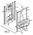
ここで図2を参照すると、冷蔵庫10の内側壁22は、全体が長方形の窪んだポケット26を含むことができる。ポケット26の上端には、該ポケットの外部へ突出するピン28が設けられている。該ピンは、水平に左右方向に移動自在に水平スライドトラック30内に保持されている。ピン28は、シュラウド20の後表面からピン28に対面する略ハート形のマルチステップトラック32に係合することができる。略ハート形のマルチステップトラック32は、以下で述べるように、シュラウド20を上位置と下位置に安定して保持するように協働する。シュラウド20は、垂直案内機構、例えば、シュラウド20に設けられた外側に突出する左右の垂直レール34によってポケット26に対して摺動自在に保持することができる。左右の垂直レール34はポケット26の左側と左側に配設された対応の溝部36に係合する。この機構または種々の他の機構を用いて、ポケット26に対して垂直移動するようにシュラウド20を拘束することができる。
Referring now to FIG. 2, the
棚ブラケット37を冷蔵庫の内部空間に露出するシュラウドの表面に支持させるようにできる。棚ブラケット37は棚16を保持し、例えば棚16の上部、或いは、図4に示す異なる実施形態では、1つ下の棚の下部を照明する発光ダイオード(LED)を使用した照明器40が設けられている。シュラウド20を移動させることによって、それに対応して棚16が移動する。
The
更に、図2を参照すると、ポケット26内に設けられたコネクタ42を内側壁22の背後に設けられた電力源に接続して、柔軟な電気ケーブル44を接続するようにできる。柔軟な電気ケーブル44は、シュラウド20の背後のポケット26内で(ジグザグ平面形態で)緩く収縮されポケット26の下部へ延設するようにできる。ポケット26の下方部分は、以下でより詳細に述べるように、冷蔵庫の内側壁22の一部分50によって覆うことができる。ここで、本明細書で使用される用語「収縮」は、ポケット26の中へ柔軟な電気ケーブル44をあらゆる形態に収縮させたり或いは折畳んだりすることを意味する。
Further, referring to FIG. 2, a
ここで図2、3を参照すると、略ハート形のマルチステップトラック32は、シュラウド20の後面からシュラウド20内へ延びる溝とすることができ、一般に、上頂点に結合する2つの下ローブを有する概ね倒立ハート形(カージオイド)を呈している。略ハート形のマルチステップトラック32は、ピン28が、2つの安定位置の間で移動するときにピン28を案内する。2つの安定位置とは、カージオイドのローブ間のノッチである位置46aにピン28がある(シュラウド20に対して)下位置および略ハート形のマルチステップトラック32の最も上の頂点の位置46bにピンがある上位置である。ピン28の上位置は、棚16の最も下の位置を表し、また、その逆の場合は反対のものとなる。下位置にあるシュラウド20(ピン28はシュラウド20の上位置46bにある)で始めると、略ハート形のマルチステップトラック32は、全体が非対称であるため、位置46bで出発して棚16およびシュラウド20の持上げによってシュラウド20に対して下方に移動するピン28は、略ハート形のマルチステップトラック32の最も左の溝に追従して、略ハート形のマルチステップトラック32の最も左のローブの位置46cに至り、そこで、ピン28は、更なる相対的下方移動に抗してトラップされる。
Referring now to FIGS. 2 and 3, the generally heart-shaped
位置46cからの棚16およびシュラウド20の下方移動は、ピン28が位置46aまで上昇することを要求し、位置46aで、ピン28は、出発した位置46bにあったときの棚位置に対して高い第2の位置に棚16を保持するように略ハート形のマルチステップトラック32を支持する。
The downward movement of
新たな、棚16およびシュラウド20の上方移動は、ピン28を、シュラウド20に対して下方に移動させて、略ハート形のマルチステップトラック32の最も右のローブの位置46dに至らしめ、位置46dで、この位置からのピン28のその後の(シュラウド20の下方移動による)上方移動は、ピン28を位置46bに戻らせる。
The new upward movement of the
そのため、消費者による棚16(従って、シュラウド20)上での連続する上方および下方移動は、棚16を、上位置と下位置との間で相安定的に移動させる。ピン28は、カージオイドトラックを通って移動するとき、略ハート形のマルチステップトラック32に追従するのに必要なピン28の左右移動に対処するために、スライドトラック30内で僅かに摺動することができる。同様の設計のカージオイドトラックは、本発明の譲受人に譲渡され、2005年2月16日に出願された欧州特許第1563762号「Easy Height Adjustment Device for Refrigerator Shelves」に全体が記載されている。同特許出願は、本願の一部をなすものとして引用する。
Thus, continuous upward and downward movement on the shelf 16 (and thus the shroud 20) by the consumer causes the
略ハート形のマルチステップトラック32とピン28の相対位置は、反転されたカージオイドトラックを用いる同様の機構を実現するために反転することができることが理解されるであろう。
It will be appreciated that the relative position of the generally heart-shaped
ここで図4を参照すると、ケーブル44は、棚ブラケット37内のエントリ部位49を通過した後、棚ブラケット37に保持されたプリント回路基板56および/またはプリント回路基板58に接続することができ、ケーブル44は、透明窓または半透明窓64または66の背後で棚ブラケット37のコンパートメント60または62に含まれる1または複数のLED40に電力を提供する。
Referring now to FIG. 4, the
棚16は、強化ガラス板とすることができるため、棚16の上部のLED40からの光は、棚16を照明することができ、一部の光は、棚16を通過して、下の棚を照明することができる。逆に、棚16の下のLED40からの光は、上の棚を通した反射によって1つ下の棚を照明することができる。
Since the
ここで図5を参照すると、ポケット26は、1つの面上で浅いトレー開口部を提供する別個の組立体68とすることができる。組立体68は、内側壁22の外側から内側壁22に取付けることができるため、ポケット26の開口面が、内側壁22に刻まれた開口部70を通して露出される。内側壁22の開口部70は、ポケット26の鉛直方向の高さに比べて、鉛直方向の高さを小さくすることができ、従って、冷蔵庫の内側壁22を通した突破口を最小にする。組立体68は、ピン28を支持し、コネクタ42およびケーブル44を保持することができる。
Referring now to FIG. 5, the
同様に図6a、6bを参照すると、一実施形態の開口部70の鉛直方向の高さ72は、シュラウド20の鉛直方向の高さ74(図3に示す)から、略ハート形のマルチステップトラック32によって規定されるその安定静止状態にある棚16の2つの位置(図3に示す)間の垂直分離76を引いた値より大きくないことになる。こうして、シュラウド20の鉛直方向の高さ74は、棚16が、その最も低い位置(図6aに示す)およびその最も高い位置(図6bに示す)の双方にあるときに開口部70を依然として覆いながら、最小にすることができる。この小さな開口部70は、小さなシュラウド20を可能にし、次に、冷蔵庫10における棚16のより密接した間隔を可能にする。より一般的には、シュラウド20は、ポケット26の開口部の鉛直方向の高さ75と棚位置の垂直分離76の和よりも小さい鉛直方向の高さ74を有するように制約することができる。この和に等しい高さを有するシュラウド20は、開口部70がポケット26と同じ高さを有する場合に必要とされることになる。シュラウド20でポケット26が覆われたままにしながら、ポケット26のサイズをこうして増加させることができることは、ケーブル44の屈曲の減少を可能にし、ケーブル44の重量が、牽引機構または同様なものなしで、ポケット26内へのケーブル44の自然な引っ込みを提供することを可能にする。
Similarly, referring to FIGS. 6 a and 6 b, the
棚16がその最も低い位置にあるとき、ケーブル44は、内側壁22の一部分50の背後に収容することができ、一方、棚16がその最も高い位置にあるとき、ケーブル44は、コネクタ42から下方に単一ループでドレープ形成することができる。全ての場合に、コネクタ42は、棚および棚ブラケット37のエントリ部位49よりも高いことになる。
When the
ここで図7a、7bを参照すると、代替の設計では、棚調整の3つ以上の異なる高さを、上述した略ハート形のマルチステップトラック32と同様の原理に従って働くが、3つ以上の安定静止位置を有する交互対枝式マルチステップトラック32′によって得ることができる。具体的には、交互対枝式マルチステップトラック32′は、ピン28がシュラウド20を支持することができる6つの安定静止位置78a〜78eを提供する。特に、この設計は、(シュラウド20上の最も高いレベルから最も低いレベルの)4つの異なるレベル80a〜80dを提供し、それらのレベルで、シュラウド20、従って棚(図7に示さず)は、冷蔵庫の内側壁22に対するシュラウド20の順次の上方移動および下方移動によって安定して位置決めすることができる。
Referring now to FIGS. 7a and 7b, in alternative designs, three or more different heights of shelf adjustment work according to the same principle as the generally heart-shaped
調整プロセス中、ピン28は、レベル80a(最も低い棚位置)の最も高い静止位置78aから、次に、上方移動、次の下方移動によってレベル80bの静止位置78bに、そして同様にして、その後レベル80cの静止位置78cに、次に、レベル80dの静止位置78dに移動することができる。引き続いての、上方移動、次の下方移動は、ピン28を上方に、最初にレベル80cの静止位置78eに、次にレベル80bの静止位置70fに、最後に再び静止位置78aに循環させる。略ハート形のマルチステップトラック32および交互対枝式マルチステップトラック32′のこれらの2つの例から、同じシュラウド20によって、棚を下方に移動させるときと対照的に、棚を上方に移動させるときに、異なる数のレベルを含む任意の数のレベル80を設けることができることが認識されるであろう。
During the adjustment process, the
図7a、7bの実施形態はまた、壁搭載式パネル82を使用することによって、冷蔵庫10の内側壁22にシュラウド20を取付ける代替の方法を示し、壁搭載式パネル82は、例えば自己タッピングネジ(図示せず)およびパネル82内の搭載穴84によって内側壁22の内部表面に取付けることができる。壁搭載式パネル82は、ポケット26を提供する別個の構成要素86を、(冷蔵庫10の内部に対して)その後表面上で支持することができ、こうした構成要素86は、内側壁22内の穴を通して嵌合することができるか、または、壁搭載式パネル82の厚さ内に全体的に含めることができる。この実施形態では、垂直レール34は、壁搭載式パネル82上に最も容易に設置することができ、対応する溝部36は、シュラウド20上に設置することができる。別個のコネクタ42′は、ケーブル44(フラットケーブルとすることができる)をプリント回路カード56に取付けることができる。
The embodiment of FIGS. 7 a, 7 b also shows an alternative method of attaching the
本発明の種々の特徴が、添付特許請求の範囲で述べられる。本発明が、その適用において本明細書で述べる構成要素の構成および配置の詳細に限定されないことが理解されるべきである。本発明は、他の実施形態が可能であり、また、種々の方法で実施または実行されることが可能である。上述の形態の変形形態および変更形態が本発明の範囲内にある。本明細書で開示され規定される発明が、述べられたかまたはテキストおよび/または図面から明らかな個々の特徴のうちの2つ以上の全ての代替の組合せに拡張されることも理解される。これらの異なる組合せは全て、本発明の種々の代替の態様を構成する。本明細書で述べる実施形態は、本発明を実施するために知られている最良の形態を説明し、当業者が本発明を利用することを可能にすることになる。 Various features of the invention are set forth in the appended claims. It should be understood that the invention is not limited in its application to the details of the construction and arrangement of components set forth herein. The invention is capable of other embodiments and of being practiced or carried out in various ways. Variations and modifications of the form described above are within the scope of the invention. It is also understood that the invention disclosed and defined herein extends to all alternative combinations of two or more of the individual features described or apparent from the text and / or drawings. All of these different combinations constitute various alternative aspects of the invention. The embodiments described herein describe the best mode known for practicing the invention and will enable those skilled in the art to utilize the invention.
Claims (18)
棚と、該棚の領域を照明するための少なくとも1つのランプとを備えた棚組立体であって、前記少なくとも1つのランプが該棚組立体に取付けられて成る棚組立体と、
摺動可能に連結される第1と第2のスライド要素を有する摺動部材であって、前記第1のスライド要素は前記冷蔵庫の内壁に取付可能であり、前記第2のスライド要素は前記棚組立体に取付可能となっている摺動部材と、
前記棚組立体を前記冷蔵庫内の第1と第2の高さに配置するように、前記第1と第2のスライド要素を第1と第2の相対位置で係脱自在に保持するデテント機構と、
前記内壁に隣接して前記棚組立体とともに移動するように取付けられたシュラウドであって、前記内壁の近傍で前記デテント機構を閉囲する閉囲空間の少なくとも一部分を形成するシュラウドと、
冷蔵庫の内部空間に露出するシュラウドの表面に取り付けられ前記棚を保持する棚ブラケットであって、前記少なくとも1つのランプが設けられて成る棚ブラケットと、
前記閉囲空間内に保持され、前記内壁上の所定部位から前記棚組立体上の所定部位へ導電性経路を形成する柔軟な導体であって、前記第1の相対位置と前記第2の相対位置との間で前記摺動部材が移動するとき、前記閉囲空間内で収縮、延展するサイズに作られた柔軟な導体とを備える棚装置。 In the adjustable shelf device of the refrigerator,
A shelf assembly comprising a shelf and at least one lamp for illuminating an area of the shelf, wherein the shelf assembly is attached to the shelf assembly;
A sliding member having first and second sliding elements that are slidably coupled, wherein the first sliding element is attachable to an inner wall of the refrigerator, and the second sliding element is the shelf A sliding member that can be attached to the assembly;
A detent mechanism for detachably holding the first and second slide elements at first and second relative positions so that the shelf assembly is disposed at first and second heights in the refrigerator. When,
A shroud mounted for movement with the shelf assembly adjacent to the inner wall, the shroud forming at least a portion of an enclosed space that encloses the detent mechanism in the vicinity of the inner wall;
A shelf bracket attached to the surface of the shroud exposed in the interior space of the refrigerator and holding the shelf, wherein the shelf bracket is provided with the at least one lamp;
The retained in enclosed space, a flexible conductor forming a conductive path to a predetermined portion position of the upper shelf assembly from a predetermined site on said inner wall, and said first relative position the second A shelf device comprising: a flexible conductor sized to contract and extend within the enclosed space when the sliding member moves between relative positions.
該ポケット部は、前記開口部を前記冷蔵庫の内側に向けて前記内壁に取付可能となっており、該ポケット部が前記シュラウドと協働して前記閉囲空間を形成する請求項1に記載の棚装置。 Further comprising a pocket having an opening,
2. The pocket portion according to claim 1, wherein the pocket portion can be attached to the inner wall with the opening portion facing the inside of the refrigerator, and the pocket portion forms the enclosed space in cooperation with the shroud. Shelf equipment.
内壁によって囲繞される開口部を有した冷蔵庫ハウジングと、
棚と、該棚の領域を照明するための少なくとも1つのランプとを備えた棚組立体であって、前記少なくとも1つのランプが該棚組立体に取付けられて成る少なくとも1の棚組立体と、
摺動可能に連結される第1と第2のスライド要素を有する第1と第2の摺動部材であって、前記第1のスライド要素は前記冷蔵庫の内壁の異なる内壁に取付けられ、前記第2のスライド要素は前記棚組立体の両側部に取付けられる第1と第2の摺動部材と、
前記棚組立体を前記冷蔵庫内の第1と第2の高さに配置するように、前記第1と第2のスライド要素を第1と第2の相対位置で係脱自在に保持するデテント機構と、
前記内壁に隣接して前記棚組立体とともに移動するように取付けられたシュラウドであって、前記内壁の近傍で前記デテント機構を閉囲する閉囲空間の少なくとも一部分を形成するシュラウドと、
冷蔵庫の内部空間に露出するシュラウドの表面に取り付けられ前記棚を保持する棚ブラケットであって、前記少なくとも1つのランプが設けられて成る棚ブラケットと、
前記閉囲空間の1つに保持され、前記内壁上の所定部位から前記棚組立体上の所定部へ導電性経路を形成する柔軟な導体であって、前記第1の相対位置と前記第2の相対位置との間で前記第1と第2の摺動部材が移動するとき、前記閉囲空間内で収縮、延展するサイズに作られた柔軟な導体とを備える冷蔵庫。 In refrigerators with adjustable shelf devices,
A refrigerator housing having an opening surrounded by an inner wall;
A shelf assembly comprising a shelf and at least one lamp for illuminating an area of the shelf, wherein the at least one shelf is attached to the shelf assembly;
First and second sliding members having first and second sliding elements slidably connected, wherein the first sliding elements are attached to different inner walls of the inner wall of the refrigerator, Two sliding elements are first and second sliding members attached to both sides of the shelf assembly;
A detent mechanism for detachably holding the first and second slide elements at first and second relative positions so that the shelf assembly is disposed at first and second heights in the refrigerator. When,
A shroud mounted for movement with the shelf assembly adjacent to the inner wall, the shroud forming at least a portion of an enclosed space that encloses the detent mechanism in the vicinity of the inner wall;
A shelf bracket attached to the surface of the shroud exposed in the interior space of the refrigerator and holding the shelf, wherein the shelf bracket is provided with the at least one lamp;
A flexible conductor that is held in one of the enclosed spaces and forms a conductive path from a predetermined portion on the inner wall to a predetermined portion on the shelf assembly, the first relative position and the second And a flexible conductor that is sized to contract and extend in the enclosed space when the first and second sliding members move between the relative positions.
前記冷蔵庫はポケット部を更に具備し、
該ポケット部は、前記内壁を貫通する前記開口部の外側に取付可能となっており、該ポケット部は前記開口を通してアクセス可能であり、該ポケット部が前記シュラウドと協働して前記閉囲空間を形成する請求項11に記載の冷蔵庫。 The at least one inner wall of the refrigerator has an opening through the at least one inner wall;
The refrigerator further comprises a pocket portion,
The pocket portion is attachable to the outside of the opening that penetrates the inner wall, the pocket portion is accessible through the opening, and the pocket portion cooperates with the shroud to form the enclosed space. The refrigerator of Claim 11 which forms.
前記棚は、
棚と、該棚の領域を照明するための少なくとも1つのランプとを備えた棚組立体であって、前記少なくとも1つのランプが該棚組立体に取付けられて成る棚組立体と、
摺動可能に連結される第1と第2のスライド要素を有する摺動部材であって、前記第1のスライド要素は前記冷蔵庫の内壁に取付可能であり、前記第2のスライド要素は前記棚組立体に取付可能となっている摺動部材と、
前記棚組立体を前記冷蔵庫内の第1と第2の高さに配置するように、前記第1と第2のスライド要素を第1と第2の相対位置で係脱自在に保持するデテント機構であって、該デテント機構は、相互係合式マルチステップトラックおよびピンを有し、一方は前記第1のスライド要素に取付けられ、一方は前記第2のスライド要素に取付けられて、前記第2のスライド要素の一連の上下動作に応答して、前記第2のスライド要素が、前記第1のスライド要素上の2つの異なる高さに安定して静止することを可能にするデテント機構と、
前記内壁に隣接して前記棚組立体とともに移動するように取付けられたシュラウドであって、前記内壁の近傍で前記デテント機構を閉囲する閉囲空間の少なくとも一部分を形成するシュラウドと、
冷蔵庫の内部空間に露出するシュラウドの表面に取り付けられ前記棚を保持する棚ブラケットであって、前記少なくとも1つのランプが設けられて成る棚ブラケットと、
前記内壁上の所定部位から前記棚組立体上の部位まで導電性経路を提供する前記閉囲空間内に保持された柔軟な導体であって、前記第1の相対位置と前記第2の相対位置との間で前記摺動部材が移動するときに前記閉囲空間内で収縮、延展するサイズに作られた柔軟な導体とを有し、
該方法は、
(a)第4の位置から前記棚組立体を持上げて、前記ピンを、前記棚組立体の更なる上動を阻止する第1の位置まで前記相互係合式マルチステップトラックを通して案内する段階と、
(b)前記棚組立体を解放して、該棚組立体の更なる下動を阻止する前記第1の位置と異なる第2の位置で前記ピンによって支持させる段階と、
(c)前記棚組立体を持上げて、前記棚組立体の更なる持上げを阻止する前記第1の位置と異なる第3の位置まで前記ピンを前記相互係合式マルチステップトラックを通して案内する段階と、
(d)前記棚組立体を解放して、前記棚組立体の更なる降下を阻止する前記第2の位置と異なる第4の位置で前記ピンによって支持させるステップとを含み、
前記デテント機構を直接操作することも、電力を切断することもなく得ることができるように照明される棚を移動するようにした冷蔵庫内の棚調整方法。 A method for adjusting a shelf in a refrigerator,
The shelf is
A shelf assembly comprising a shelf and at least one lamp for illuminating an area of the shelf, wherein the shelf assembly is attached to the shelf assembly;
A sliding member having first and second sliding elements that are slidably coupled, wherein the first sliding element is attachable to an inner wall of the refrigerator, and the second sliding element is the shelf A sliding member that can be attached to the assembly;
A detent mechanism for detachably holding the first and second slide elements at first and second relative positions so that the shelf assembly is disposed at first and second heights in the refrigerator. The detent mechanism includes an interengaging multi-step track and a pin, one attached to the first slide element and one attached to the second slide element, In response to a series of up and down movements of the slide element, the detent mechanism allowing the second slide element to rest stably at two different heights on the first slide element;
A shroud mounted for movement with the shelf assembly adjacent to the inner wall, the shroud forming at least a portion of an enclosed space that encloses the detent mechanism in the vicinity of the inner wall;
A shelf bracket attached to the surface of the shroud exposed in the interior space of the refrigerator and holding the shelf, wherein the shelf bracket is provided with the at least one lamp;
A flexible conductor held in the enclosed space for providing a conductive path from a predetermined site on the inner wall to a site on the shelf assembly, the first relative position and the second relative position A flexible conductor sized to contract and extend in the enclosed space when the sliding member moves between
The method
(A) lifting the shelf assembly from a fourth position and guiding the pins through the interengaging multi-step track to a first position that prevents further upward movement of the shelf assembly;
(B) releasing the shelf assembly to be supported by the pins in a second position different from the first position to prevent further downward movement of the shelf assembly;
(C) lifting the shelf assembly and guiding the pins through the interengaging multi-step track to a third position different from the first position that prevents further lifting of the shelf assembly;
(D) releasing the shelf assembly to be supported by the pins at a fourth position different from the second position to prevent further lowering of the shelf assembly;
The shelf adjustment method in the refrigerator which moved the shelf illuminated so that it could obtain without operating the said detent mechanism directly or cut | disconnecting electric power.
Applications Claiming Priority (3)
| Application Number | Priority Date | Filing Date | Title |
|---|---|---|---|
| US37341010P | 2010-08-13 | 2010-08-13 | |
| US61/373,410 | 2010-08-13 | ||
| PCT/US2011/047592 WO2012021807A2 (en) | 2010-08-13 | 2011-08-12 | Refrigerator shelf adjustment system with in-shelf lighting |
Publications (3)
| Publication Number | Publication Date |
|---|---|
| JP2013540974A JP2013540974A (en) | 2013-11-07 |
| JP2013540974A5 JP2013540974A5 (en) | 2014-10-02 |
| JP6039557B2 true JP6039557B2 (en) | 2016-12-07 |
Family
ID=44533175
Family Applications (1)
| Application Number | Title | Priority Date | Filing Date |
|---|---|---|---|
| JP2013524892A Expired - Fee Related JP6039557B2 (en) | 2010-08-13 | 2011-08-12 | Refrigerator shelf adjustment system with in-shelf lighting |
Country Status (7)
| Country | Link |
|---|---|
| US (1) | US8911042B2 (en) |
| EP (1) | EP2603751A2 (en) |
| JP (1) | JP6039557B2 (en) |
| KR (1) | KR101971166B1 (en) |
| CN (1) | CN103069234B (en) |
| BR (1) | BR112013003119A2 (en) |
| WO (1) | WO2012021807A2 (en) |
Families Citing this family (28)
| Publication number | Priority date | Publication date | Assignee | Title |
|---|---|---|---|---|
| IT1403144B1 (en) * | 2010-11-22 | 2013-10-04 | Illinois Tool Works | ADJUSTABLE SUPPORT DEVICE IN HEIGHT FOR AN INTERNAL SUPPORT PLAN FOR A HOUSEHOLD APPLIANCE |
| KR102014148B1 (en) * | 2012-10-29 | 2019-10-21 | 엘지전자 주식회사 | Refrigerator |
| US9212848B2 (en) | 2013-03-15 | 2015-12-15 | Whirlpool Corporation | Apparatus, system, and method for storage in a refrigerated appliance |
| US9766010B2 (en) | 2013-04-30 | 2017-09-19 | Whirlpool Corporation | Lighting for shelf divider in refrigerator |
| DE102013214000A1 (en) | 2013-07-17 | 2015-01-22 | BSH Bosch und Siemens Hausgeräte GmbH | Domestic refrigeration appliance with at least one light source and a receptacle for a support floor |
| DE102013220083A1 (en) * | 2013-10-02 | 2015-04-02 | BSH Bosch und Siemens Hausgeräte GmbH | Domestic refrigerator with a forming in the interior hollow pocket on a vertical wall of an inner container |
| DE102013220078A1 (en) * | 2013-10-02 | 2015-04-02 | BSH Bosch und Siemens Hausgeräte GmbH | Domestic refrigerating appliance with a receiving element for a shelf, which has an OLED light source |
| WO2015089734A1 (en) * | 2013-12-17 | 2015-06-25 | 合肥华凌股份有限公司 | Refrigeration equipment and light-emitting shelf assembly thereof |
| CN104344675B (en) * | 2014-02-08 | 2016-11-23 | 海尔集团公司 | Rack component and there is the refrigerator of this rack component |
| KR101622231B1 (en) * | 2014-04-18 | 2016-05-18 | 엘지전자 주식회사 | Refrigerator |
| FR3025708B1 (en) * | 2014-09-12 | 2017-02-03 | Actuel Pharm | DISPLAY PANEL, PRESENTATION ASSEMBLY, AND METHOD OF MANUFACTURING |
| US9989232B2 (en) | 2015-03-17 | 2018-06-05 | Whirlpool Corporation | Shelf height adjusting flippers having an integrated electrical contact |
| BR102015006334B1 (en) * | 2015-03-20 | 2022-09-13 | Whirlpool S.A. | ADJUSTABLE SHELF SYSTEM FOR HOUSEHOLD APPLIANCES |
| US9418267B1 (en) * | 2015-08-10 | 2016-08-16 | Ground Star Llc | Modular RFID shelving |
| CN106895653B (en) * | 2015-12-18 | 2020-01-14 | 松下电器研究开发(苏州)有限公司 | Luminous shelf assembly and refrigerator with same |
| KR102314318B1 (en) | 2016-01-04 | 2021-10-20 | 엘지전자 주식회사 | refrigerator |
| WO2017119573A1 (en) * | 2016-01-04 | 2017-07-13 | 엘지전자 주식회사 | Refrigerator |
| US10174992B2 (en) * | 2016-09-01 | 2019-01-08 | Whirlpool Corporation | Variable width deli cover |
| CN106764681B (en) * | 2016-12-22 | 2024-03-15 | 赛尔富电子有限公司 | LED strip lamp for shelf nameplate |
| US11401701B2 (en) | 2017-04-25 | 2022-08-02 | Whirlpool Corporation | Refrigeration apparatus configured to capture atmospheric water |
| CN107192213A (en) * | 2017-06-29 | 2017-09-22 | 青岛海尔电冰箱有限公司 | lighting device for refrigerator |
| CN107166865B (en) * | 2017-06-29 | 2019-12-06 | 青岛海尔电冰箱有限公司 | lighting device for refrigerator |
| USD840182S1 (en) | 2017-12-21 | 2019-02-12 | Jones Plastic And Engineering Company, Llc | Pull-out LED shelf |
| US10451339B1 (en) | 2018-06-20 | 2019-10-22 | Haier Us Appliance Solutions, Inc. | Illuminated adjustable divider for a storage bin of a refrigerator appliance |
| US10408532B1 (en) | 2018-06-20 | 2019-09-10 | Haier Us Appliance Solutions, Inc. | Illuminated adjustable divider for a storage bin of a refrigerator appliance |
| CN112013619B (en) * | 2019-05-29 | 2021-10-29 | 青岛海尔电冰箱有限公司 | Refrigerator with sliding rail routing mechanism |
| CN113229627B (en) * | 2021-06-04 | 2022-08-09 | 山西大同大学 | Portable wardrobe adjusting device |
| US11620868B2 (en) | 2021-07-22 | 2023-04-04 | Trinity Axis Inc. | Techniques to dispense an item and release a jammed item from a dispensing system |
Family Cites Families (44)
| Publication number | Priority date | Publication date | Assignee | Title |
|---|---|---|---|---|
| US3551612A (en) * | 1968-07-11 | 1970-12-29 | Westinghouse Electric Corp | Flexible conductor horizontal loop-supporting apparatus |
| US3506325A (en) * | 1968-07-25 | 1970-04-14 | Gen Electric | Refrigerator including illuminated cabinet shelf |
| US3516369A (en) * | 1968-09-27 | 1970-06-23 | Gen Electric | Vertically adjustable shelf |
| US4489995A (en) | 1981-08-14 | 1984-12-25 | Tyler Refrigeration Corporation | Adjustable electrical outlet assembly |
| DE3544446C1 (en) * | 1985-12-16 | 1987-01-08 | Bosch Siemens Hausgeraete | Cooling device, in particular domestic refrigerator |
| US4689726A (en) * | 1986-02-28 | 1987-08-25 | Kretzschmar Thomas E | Lighting mechanism |
| JPS6315507U (en) * | 1986-07-16 | 1988-02-01 | ||
| US5034861A (en) * | 1989-12-22 | 1991-07-23 | Raytheon Company | Shelf track lighting |
| US5357874A (en) * | 1992-07-30 | 1994-10-25 | Abco Office Furniture Inc. | Channel assembly with snap-in insert |
| US5287252A (en) * | 1993-01-14 | 1994-02-15 | Sub-Zero Freezer Company, Inc. | Adjustable illuminated refrigerator shelf |
| US5606919A (en) * | 1995-06-07 | 1997-03-04 | Haworth, Inc. | Space-dividing fence for power and/or communication distribution |
| JPH09250870A (en) | 1996-03-19 | 1997-09-22 | Toshiba Corp | Shelf structure of refrigerator |
| US6527406B1 (en) * | 1996-04-12 | 2003-03-04 | Powerwall, Inc. | Integrally powered modular furniture |
| US6283608B1 (en) * | 1997-02-28 | 2001-09-04 | Patricia Ann Straat | Light fixture for shelving |
| US6042244A (en) * | 1998-02-02 | 2000-03-28 | Witkoski; William | Lighted display system |
| US6113198A (en) * | 1998-09-16 | 2000-09-05 | Howard Miller Clock Company | Collectibles display cabinet with interior electrical outlets |
| EP1110490A1 (en) * | 1999-12-24 | 2001-06-27 | USM Holding AG | Furniture system with modular lighting installation |
| JP4111038B2 (en) * | 2000-03-27 | 2008-07-02 | 三菱電機株式会社 | refrigerator |
| ITTO20011191A1 (en) * | 2001-12-18 | 2003-06-18 | Itw Ind Components Srl | SERVICE DEVICE FOR A REFRIGERATOR AND REFRIGERATOR PROVIDED WITH A DEVICE. |
| US6930244B1 (en) * | 2003-06-24 | 2005-08-16 | Michael W. Nebel | Flexible wiring and tubing carrier for slide-out rooms |
| US7163305B2 (en) * | 2003-06-25 | 2007-01-16 | Gemtron Corporation | Illuminated shelf |
| ITTO20040087A1 (en) | 2004-02-17 | 2004-05-17 | Itw Ind Componemts S R L | DEVICE FOR QUICK DISPLACEMENT OF THE POSITION IN HEIGHT OF AN INTERNAL PLAN OF A HOME APPLIANCE SUCH AS A REFRIGERATOR OR FREEZER |
| ITMI20040280U1 (en) | 2004-06-11 | 2004-09-11 | Whirlpool Co | MULTI-PURPOSE SUPPORT FOR SHELVES OF REFRIGERATING OR SIMILAR APPLIANCES, PARTICULARLY SUITABLE FOR MODULAR APPLIANCES |
| US7784888B2 (en) * | 2004-10-26 | 2010-08-31 | Lg Electronics Inc. | Refrigerator |
| US20060087208A1 (en) * | 2004-10-26 | 2006-04-27 | Lg Electronics Inc. | Refrigerator |
| GB0427835D0 (en) * | 2004-12-20 | 2005-01-19 | Artform Internat Ltd | Product display |
| ITTO20050104A1 (en) * | 2005-02-22 | 2006-08-23 | Itw Ind Components Srl | DRAWER CONTAINER DEVICE FOR A APPLIANCE, IN PARTICULAR FOR THE SECTOR FRESH FOOD OF A REFRIGERATOR OR FREEZER |
| ATE479998T1 (en) * | 2005-09-02 | 2010-09-15 | Electrolux Home Prod Corp Nv | REFRIGERATOR WITH MOVING PART WITH NON-CONTACT ENERGY TRANSFER |
| US7338180B2 (en) * | 2005-12-21 | 2008-03-04 | Whirlpool Corporation | Lighted shelf assembly for a refrigerator |
| EP1950514B1 (en) * | 2007-01-25 | 2009-09-09 | Electrolux Home Products Corporation N.V. | Food cooling appliance |
| US7766502B2 (en) * | 2007-05-07 | 2010-08-03 | Tresco International Ltd. Co. | Self-illuminated structural panel units and systems including the same |
| DE102007029182B4 (en) * | 2007-06-25 | 2019-09-12 | BSH Hausgeräte GmbH | The refrigerator |
| US20090021927A1 (en) * | 2007-07-20 | 2009-01-22 | Electrolux Home Products, Inc. | Refrigerator shelf led lighting |
| CN101772683B (en) * | 2007-07-31 | 2012-09-19 | 伊莱克斯家用产品公司 | Food refrigeration appliance with illuminated shelves, and method of producing the illuminated shelves |
| WO2009079209A1 (en) * | 2007-12-17 | 2009-06-25 | Illinois Tool Works Inc. | Inductively powered light assembly |
| ITTO20080436A1 (en) * | 2008-06-06 | 2009-12-07 | Itw Ind Components S R L Co N | ADJUSTABLE SUPPORT DEVICE IN HEIGHT FOR AN INTERNAL ELEMENT OF SUPPORT OF A APPLIANCE, SUCH AS A DISHWASHER BASKET OR A FRIDGE PLAN |
| JP2010065921A (en) * | 2008-09-10 | 2010-03-25 | Mitsubishi Electric Corp | Refrigerator |
| EP2464935A1 (en) * | 2009-08-14 | 2012-06-20 | Illinois Tool Works Inc. | Inductively powered lighting assembly |
| WO2011115957A2 (en) * | 2010-03-17 | 2011-09-22 | Illinois Tool Works Inc. | High-efficiency wireless lighting system |
| US20110273867A1 (en) * | 2010-05-05 | 2011-11-10 | Premier Custom Built, Inc. | Adjustable shelves with lighting fixture |
| WO2011143059A1 (en) * | 2010-05-10 | 2011-11-17 | Illinois Tool Works Inc. | Refrigerator shelf adjustment system with in-shelf lighting |
| US8876314B2 (en) * | 2010-06-28 | 2014-11-04 | Hefei Midea Rongshida Refrigerator Co., Ltd. | Drawer-type refrigerator with a lighting device |
| US8322873B2 (en) * | 2010-11-03 | 2012-12-04 | Varroccorp Holding Bv | Lighting system for appliance |
| IT1403144B1 (en) * | 2010-11-22 | 2013-10-04 | Illinois Tool Works | ADJUSTABLE SUPPORT DEVICE IN HEIGHT FOR AN INTERNAL SUPPORT PLAN FOR A HOUSEHOLD APPLIANCE |
-
2011
- 2011-08-12 EP EP11746129.3A patent/EP2603751A2/en not_active Withdrawn
- 2011-08-12 CN CN201180038701.9A patent/CN103069234B/en not_active Expired - Fee Related
- 2011-08-12 BR BR112013003119A patent/BR112013003119A2/en not_active IP Right Cessation
- 2011-08-12 WO PCT/US2011/047592 patent/WO2012021807A2/en active Application Filing
- 2011-08-12 KR KR1020137003302A patent/KR101971166B1/en active IP Right Grant
- 2011-08-12 JP JP2013524892A patent/JP6039557B2/en not_active Expired - Fee Related
- 2011-08-12 US US13/703,459 patent/US8911042B2/en not_active Expired - Fee Related
Also Published As
| Publication number | Publication date |
|---|---|
| CN103069234A (en) | 2013-04-24 |
| WO2012021807A3 (en) | 2012-08-23 |
| KR101971166B1 (en) | 2019-04-22 |
| WO2012021807A2 (en) | 2012-02-16 |
| BR112013003119A2 (en) | 2016-06-28 |
| KR20130091739A (en) | 2013-08-19 |
| EP2603751A2 (en) | 2013-06-19 |
| US20130088136A1 (en) | 2013-04-11 |
| JP2013540974A (en) | 2013-11-07 |
| CN103069234B (en) | 2016-01-20 |
| US8911042B2 (en) | 2014-12-16 |
Similar Documents
| Publication | Publication Date | Title |
|---|---|---|
| JP6039557B2 (en) | Refrigerator shelf adjustment system with in-shelf lighting | |
| US9455506B2 (en) | Electrical connector for adjustable refrigerator shelf | |
| EP2799796B1 (en) | Lighting for shelf divider in refrigerator | |
| JP4636819B2 (en) | shelf | |
| EP3032200A1 (en) | Refrigerator with shelf lighting | |
| EP1950514A1 (en) | Food cooling appliance | |
| TR201808536T4 (en) | Refrigerator. | |
| EP2910881A1 (en) | Lighting units for refrigerator drawers and baskets | |
| EP2144539A1 (en) | Dispenser with led lighting | |
| RU2332622C2 (en) | Refrigerator | |
| KR101695696B1 (en) | Refrigerator | |
| KR20110034271A (en) | A refrigerator and a shelf for the refrigeraor | |
| KR102463113B1 (en) | Light-controlled divider for storage compartments for refrigerator appliances | |
| JP5114915B2 (en) | refrigerator | |
| CN210374281U (en) | Lighting structure for drawer of refrigerator | |
| EP3242982B1 (en) | Modular wall system and panel element for use in such a system | |
| RU59305U1 (en) | PLATE FOR INSTALLING COIN PLAY AUTOMATIC MACHINE | |
| JP2007285632A (en) | Refrigerator | |
| KR20110011502A (en) | Refrigerator | |
| JP5355163B2 (en) | Electric lifting cabinet | |
| ES2926048T3 (en) | Extraction guide for mobile drawer elements related to a furniture or appliance frame and furniture or appliance | |
| JP2011039754A (en) | Illumination apparatus, and illumination system in data center | |
| KR101553947B1 (en) | Refrigerator | |
| CN214037991U (en) | Lamp and open cabinet | |
| CN216202781U (en) | Mounting bracket, plywood postposition lamp and display cabinet |
Legal Events
| Date | Code | Title | Description |
|---|---|---|---|
| A521 | Request for written amendment filed |
Free format text: JAPANESE INTERMEDIATE CODE: A523 Effective date: 20140812 |
|
| A621 | Written request for application examination |
Free format text: JAPANESE INTERMEDIATE CODE: A621 Effective date: 20140812 |
|
| A977 | Report on retrieval |
Free format text: JAPANESE INTERMEDIATE CODE: A971007 Effective date: 20150424 |
|
| A131 | Notification of reasons for refusal |
Free format text: JAPANESE INTERMEDIATE CODE: A131 Effective date: 20150512 |
|
| A521 | Request for written amendment filed |
Free format text: JAPANESE INTERMEDIATE CODE: A523 Effective date: 20150812 |
|
| A131 | Notification of reasons for refusal |
Free format text: JAPANESE INTERMEDIATE CODE: A131 Effective date: 20160209 |
|
| A521 | Request for written amendment filed |
Free format text: JAPANESE INTERMEDIATE CODE: A523 Effective date: 20160509 |
|
| TRDD | Decision of grant or rejection written | ||
| A01 | Written decision to grant a patent or to grant a registration (utility model) |
Free format text: JAPANESE INTERMEDIATE CODE: A01 Effective date: 20161004 |
|
| A61 | First payment of annual fees (during grant procedure) |
Free format text: JAPANESE INTERMEDIATE CODE: A61 Effective date: 20161104 |
|
| R150 | Certificate of patent or registration of utility model |
Ref document number: 6039557 Country of ref document: JP Free format text: JAPANESE INTERMEDIATE CODE: R150 |
|
| R250 | Receipt of annual fees |
Free format text: JAPANESE INTERMEDIATE CODE: R250 |
|
| R250 | Receipt of annual fees |
Free format text: JAPANESE INTERMEDIATE CODE: R250 |
|
| R250 | Receipt of annual fees |
Free format text: JAPANESE INTERMEDIATE CODE: R250 |
|
| LAPS | Cancellation because of no payment of annual fees |