JP6039055B2 - Device for closing a bag or the like with improved tactile sensation and acoustic effect, bag obtained thereby, and manufacturing method - Google Patents
Device for closing a bag or the like with improved tactile sensation and acoustic effect, bag obtained thereby, and manufacturing method Download PDFInfo
- Publication number
- JP6039055B2 JP6039055B2 JP2015503859A JP2015503859A JP6039055B2 JP 6039055 B2 JP6039055 B2 JP 6039055B2 JP 2015503859 A JP2015503859 A JP 2015503859A JP 2015503859 A JP2015503859 A JP 2015503859A JP 6039055 B2 JP6039055 B2 JP 6039055B2
- Authority
- JP
- Japan
- Prior art keywords
- closure device
- contoured
- closure
- members
- complementary
- Prior art date
- Legal status (The legal status is an assumption and is not a legal conclusion. Google has not performed a legal analysis and makes no representation as to the accuracy of the status listed.)
- Active
Links
- 238000004519 manufacturing process Methods 0.000 title claims description 6
- 230000000694 effects Effects 0.000 title description 19
- 230000001976 improved effect Effects 0.000 title description 3
- 230000035807 sensation Effects 0.000 title description 3
- 230000000295 complement effect Effects 0.000 claims description 26
- 230000000737 periodic effect Effects 0.000 claims description 21
- -1 polyethylene Polymers 0.000 claims description 6
- 239000004698 Polyethylene Substances 0.000 claims description 3
- 239000004743 Polypropylene Substances 0.000 claims description 3
- 229920000573 polyethylene Polymers 0.000 claims description 3
- 229920001155 polypropylene Polymers 0.000 claims description 3
- 238000000034 method Methods 0.000 claims 5
- 230000000712 assembly Effects 0.000 description 7
- 238000000429 assembly Methods 0.000 description 7
- 239000000463 material Substances 0.000 description 5
- 230000003321 amplification Effects 0.000 description 2
- 238000001125 extrusion Methods 0.000 description 2
- 239000012530 fluid Substances 0.000 description 2
- 235000019589 hardness Nutrition 0.000 description 2
- 239000007788 liquid Substances 0.000 description 2
- 238000003199 nucleic acid amplification method Methods 0.000 description 2
- 230000002093 peripheral effect Effects 0.000 description 2
- 235000019615 sensations Nutrition 0.000 description 2
- 238000000926 separation method Methods 0.000 description 2
- 235000009854 Cucurbita moschata Nutrition 0.000 description 1
- 240000001980 Cucurbita pepo Species 0.000 description 1
- 235000009852 Cucurbita pepo Nutrition 0.000 description 1
- 230000005489 elastic deformation Effects 0.000 description 1
- 238000001192 hot extrusion Methods 0.000 description 1
- 238000003780 insertion Methods 0.000 description 1
- 230000037431 insertion Effects 0.000 description 1
- 238000012986 modification Methods 0.000 description 1
- 230000004048 modification Effects 0.000 description 1
- 229920000098 polyolefin Polymers 0.000 description 1
- 238000007789 sealing Methods 0.000 description 1
- 238000010008 shearing Methods 0.000 description 1
- 235000020354 squash Nutrition 0.000 description 1
- 230000001360 synchronised effect Effects 0.000 description 1
- 230000007704 transition Effects 0.000 description 1
- 238000003466 welding Methods 0.000 description 1
Images


Classifications
-
- B—PERFORMING OPERATIONS; TRANSPORTING
- B65—CONVEYING; PACKING; STORING; HANDLING THIN OR FILAMENTARY MATERIAL
- B65D—CONTAINERS FOR STORAGE OR TRANSPORT OF ARTICLES OR MATERIALS, e.g. BAGS, BARRELS, BOTTLES, BOXES, CANS, CARTONS, CRATES, DRUMS, JARS, TANKS, HOPPERS, FORWARDING CONTAINERS; ACCESSORIES, CLOSURES, OR FITTINGS THEREFOR; PACKAGING ELEMENTS; PACKAGES
- B65D33/00—Details of, or accessories for, sacks or bags
- B65D33/16—End- or aperture-closing arrangements or devices
- B65D33/25—Riveting; Dovetailing; Screwing; using press buttons or slide fasteners
- B65D33/2508—Riveting; Dovetailing; Screwing; using press buttons or slide fasteners using slide fasteners with interlocking members having a substantially uniform section throughout the length of the fastener; Sliders therefor
- B65D33/2541—Riveting; Dovetailing; Screwing; using press buttons or slide fasteners using slide fasteners with interlocking members having a substantially uniform section throughout the length of the fastener; Sliders therefor characterised by the slide fastener, e.g. adapted to interlock with a sheet between the interlocking members having sections of particular shape
- B65D33/255—Riveting; Dovetailing; Screwing; using press buttons or slide fasteners using slide fasteners with interlocking members having a substantially uniform section throughout the length of the fastener; Sliders therefor characterised by the slide fastener, e.g. adapted to interlock with a sheet between the interlocking members having sections of particular shape being provided with special visual, audible or tactile indicating means, e.g. indicating proper engagement
-
- B—PERFORMING OPERATIONS; TRANSPORTING
- B65—CONVEYING; PACKING; STORING; HANDLING THIN OR FILAMENTARY MATERIAL
- B65D—CONTAINERS FOR STORAGE OR TRANSPORT OF ARTICLES OR MATERIALS, e.g. BAGS, BARRELS, BOTTLES, BOXES, CANS, CARTONS, CRATES, DRUMS, JARS, TANKS, HOPPERS, FORWARDING CONTAINERS; ACCESSORIES, CLOSURES, OR FITTINGS THEREFOR; PACKAGING ELEMENTS; PACKAGES
- B65D33/00—Details of, or accessories for, sacks or bags
- B65D33/16—End- or aperture-closing arrangements or devices
- B65D33/25—Riveting; Dovetailing; Screwing; using press buttons or slide fasteners
- B65D33/2508—Riveting; Dovetailing; Screwing; using press buttons or slide fasteners using slide fasteners with interlocking members having a substantially uniform section throughout the length of the fastener; Sliders therefor
- B65D33/2541—Riveting; Dovetailing; Screwing; using press buttons or slide fasteners using slide fasteners with interlocking members having a substantially uniform section throughout the length of the fastener; Sliders therefor characterised by the slide fastener, e.g. adapted to interlock with a sheet between the interlocking members having sections of particular shape
- B65D33/2558—Riveting; Dovetailing; Screwing; using press buttons or slide fasteners using slide fasteners with interlocking members having a substantially uniform section throughout the length of the fastener; Sliders therefor characterised by the slide fastener, e.g. adapted to interlock with a sheet between the interlocking members having sections of particular shape the slide fastener having a non-constant section throughout the length of the fastener, e.g. slightly undulated interlocking members or castellated stringers
-
- Y—GENERAL TAGGING OF NEW TECHNOLOGICAL DEVELOPMENTS; GENERAL TAGGING OF CROSS-SECTIONAL TECHNOLOGIES SPANNING OVER SEVERAL SECTIONS OF THE IPC; TECHNICAL SUBJECTS COVERED BY FORMER USPC CROSS-REFERENCE ART COLLECTIONS [XRACs] AND DIGESTS
- Y10—TECHNICAL SUBJECTS COVERED BY FORMER USPC
- Y10T—TECHNICAL SUBJECTS COVERED BY FORMER US CLASSIFICATION
- Y10T24/00—Buckles, buttons, clasps, etc.
- Y10T24/45—Separable-fastener or required component thereof [e.g., projection and cavity to complete interlock]
- Y10T24/45152—Each mating member having similarly shaped, sized, and operated interlocking or intermeshable face
- Y10T24/45157—Zipper-type [e.g., slider]
- Y10T24/45168—Zipper-type [e.g., slider] for container [e.g., bag]
Description
本発明は、バッグ、袋等の閉鎖装置の分野に関する。 The present invention relates to the field of closure devices for bags, bags and the like.
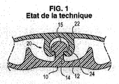
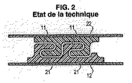
更に正確には、本発明は、添付図1及び図2に非限定的な例として示すような、それぞれの対向する支持壁12、22上に担持される2つの相補的に輪郭付けされた部材10、20に基づく閉鎖装置に関する。
More precisely, the present invention relates to two complementary contoured members carried on respective
図1及び図2に例示される装置の多数の変形実施態様がすでに提案されており、本発明の分野に属する。 Numerous variants of the device illustrated in FIGS. 1 and 2 have already been proposed and belong to the field of the invention.
図1は、前述の相補的に輪郭付けされた部材が、相補的雄/雌部材で構成される典型的な実施態様を例示する。雄部材は壁12と一体のステム14を含み、かつ上部に広げた突起15を備えるが、雌部材20は突起15に対して断面において相補的なキャビティを有する末端部を備えた溝24からなる。
FIG. 1 illustrates an exemplary embodiment in which the above-described complementary contoured members are composed of complementary male / female members. The male member includes a
図2は、相補的に輪郭付けされた部材10、20が、フック11及び21からなる、もう1つの変形実施態様を表す。
FIG. 2 represents another variant embodiment in which the complementary contoured
本発明の全体的な目的は、前述の装置を閉じる際あるいは開ける際に、すなわちそれぞれ輪郭付けされた部材10、20の係合及びその分離中に、触感及び音響効果を発生させるように、かかる既知の輪郭付けされた部材に改良を提案することである。
The overall object of the present invention is to generate tactile and acoustic effects when closing or opening the aforementioned device, i.e. during engagement and separation of the contoured
前述の装置の閉じる際あるいは開ける際に、かかる触感及び音響効果を発生させるために、様々な装置がすでに提案されている。 Various devices have already been proposed to generate such tactile and acoustic effects when closing or opening the aforementioned devices.
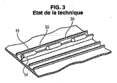
かかる既知の装置の例は、特許文献1、特許文献2、特許文献3、特許文献4、特許文献5に記載される。添付図3に見られるように、既知の配列は通常2つの輪郭付けされた部材の一方、例えば図3に示されるような雄輪郭部材10に沿って周期的な変形又は切り欠き30を、部材10、20のそれぞれの係合において硬度が確保されている点及び弱い点がこのように連続するよう画定している。
Examples of such known devices are described in
このように提案された手段は、ある程度の触感及び音響効果を実際に発生させることができる。しかしながら、これまで提案された手段によりこのようにして得られた効果は、限定された状態に留まっている。 The means proposed in this way can actually generate a certain amount of tactile sensation and sound effects. However, the effects thus obtained by the means proposed so far remain limited.
このような状況において、本発明の目的は、とりわけ、触感及び音響効果を向上させるように先行技術の既知の装置を改良することにある。 In such a situation, it is an object of the present invention, among other things, to improve the prior art known devices so as to improve the tactile and acoustic effects.
この目的は、2つの相補的に輪郭付けされた部材アセンブリを含むバッグ等の閉鎖装置により、本発明の範囲において達成される。本発明の閉鎖装置は、2つの相補的に輪郭付けされた部材アセンブリの各々が、多重クロージャを形成する少なくとも2つの輪郭付けされた取り付け要素を含み、これらの輪郭付けされた取り付け要素はその全長にわたって分布した周期的な押潰部(押し潰し部)を有し、前記輪郭付けされた取り付け要素はそれぞれ、それらがその上に一体的に形成される1つの支持マットにより担持され、前記支持マットは、1つの支持壁上に固定されるように設計され、前記支持マットは輪郭付けされた取り付け要素の全幅よりも大きな幅を有することを特徴とする。 This object is achieved within the scope of the present invention by a closure device such as a bag comprising two complementary contoured member assemblies. The closure device of the present invention includes at least two contoured attachment elements, each of two complementary contoured member assemblies forming a multiple closure, the contoured attachment elements having their full length. a periodic crushing unit distributed over (crushed portion), the contoured mounting elements respectively, they are supported by one supporting mat that will be integrally formed thereon, said supporting mat Is designed to be fixed on one support wall , characterized in that the support mat has a width greater than the total width of the contoured mounting element.
出願人は、本発明に従い、非常に特異的な三部材 − つまり、1)閉じ部材(クロージャ)の多重化、2)周期的な押潰部、及び3)取り付け要素と一体的に形成された支持マット − を組み合わせることにより、取り付け要素で発生した共振現象が支持マットで振動モードで伝播し、増幅効果を引き起こすことで、先行技術と比較して改良された効果をもたらすことを見出した。 In accordance with the present invention, Applicant has formed a very specific three-piece- ie, 1) multiplexing of closure members (closures), 2) periodic crushing portions , and 3) integrally formed with attachment elements supporting mat - by combining the resonance phenomenon generated in the mounting element propagates in the vibration mode in the supporting mat, by causing amplification effect has been found to result in the prior art and the effect which is improved compared.
本発明はさらに、かかる閉鎖装置を備えたバッグ又は袋に関する。 The invention further relates to a bag or bag comprising such a closure device.
本発明はさらに、周期的な押し潰しステップを含むかかる閉鎖装置又はバッグを製造する方法に関する。 The invention further relates to a method of manufacturing such a closure device or bag comprising a periodic crushing step.
本発明の他の有利な特徴によれば、
− 各支持マットは、第1部分と、第2部分と、中央部分とを含み、取り付け要素は支持マットの中央部分から延びるとともに当該中央部分と一体に形成され、支持マットの第1部分及び第2部分は中央部分と一体に形成されるとともに前記取り付け要素の両側に延びており、
− 各支持マットの第1及び第2部分の幅が、中央部分の幅の5倍未満、好ましくは、約2倍であり、
− 輪郭付けされた取り付け要素に面して配置された支持マットの中央部分が、クロージャから外側に凸のドーム形状を有し、
− 輪郭付けされた取り付け要素に面する支持マットの中央部分の厚さが、輪郭付けされた取り付け要素の外側の支持マットの第1部分及び第2部分の厚さよりも大きく、
− クロージャが、ポリエチレン又はポリプロピレンで形成され、
− 周期的な押潰部のピッチが、2〜7.5mmである。
According to another advantageous feature of the invention,
Each support mat includes a first portion, a second portion, and a central portion, and the attachment element extends from the central portion of the support mat and is integrally formed with the central portion; The two parts are formed integrally with the central part and extend on both sides of the mounting element;
- the width of the first and second portions of each support mat, 5 Baihitsuji full width of the central portion, good Mashiku is about 2-fold,
-The central part of the support mat arranged facing the contoured mounting element has a dome shape convex outward from the closure;
The thickness of the central part of the support mat facing the contoured mounting element is greater than the thickness of the first part and the second part of the support mat outside the contoured mounting element;
The closure is formed of polyethylene or polypropylene;
-The pitch of a periodic crushing part is 2-7.5 mm.
本発明の他の特徴、目的及び利点は、以下に続く、非限定的な例として与えられる添付図面に関する詳細な説明により理解されるであろう。 Other features, objects and advantages of the present invention will be understood by the following detailed description of the accompanying drawings given by way of non-limiting example.
添付図4は本発明に従った閉鎖装置を示し、該閉鎖装置は、2つの相補的に輪郭付けされた部材アセンブリ110、210の一方をそれぞれが支承する2つの平行な支持マット100、200からなる、2つの相補的部材A及びBを含む。
Accompanying FIG. 4 shows a closure device according to the present invention from two
すでに示したように、2つの相補的に輪郭付けされた部材アセンブリ110、210の各々は、多重クロージャを形成する少なくとも2つの輪郭付けされた取り付け要素を含む。
As already indicated, each of the two complementary contoured
更に正確には、図4に例示した非限定的な実施態様によれば、2つのアセンブリ110、210は、対称であり、かつ各々が4つの輪郭付けされた取り付け要素112、114、116、118;212、214、216、218を含む。この図4によれば、輪郭付けされた取り付け要素112、114、116、118;212、214、216、218の各々は、矢じりのように形作られた、クロージャ全体に沿って一定の直線部を有する輪郭付けされた部材からなる。実際にこれら輪郭付けされた取り付け要素の各々は、マット100又は200に対向する自由端に拡大ヘッド、例えば115を備えた、マット100又は200に全体的に直交し、かつマット100又は200と一体のステム、例えば113を含む。拡大ヘッド115は、マット100又は200に直交するステム113の正中面に対して対称であっても良いし、又は前記正中面に対して非対称であっても良い。好適には、支持マット100又は200に向けられた拡大ヘッド115の面は、ステム113から離れて、それぞれの支持マットに向かって少なくとも僅かに延出し、2つのマット100及び200上にそれぞれ与えられた輪郭付けされた部材112、114、116、118;212、214、216、218の相互の取り付けを強化するアンダカットを形成する。
More precisely, according to the non-limiting embodiment illustrated in FIG. 4, the two
更に正確には、図4に示す特定の実施態様によれば、4つの輪郭付けされた取り付け要素112、114、116、118;212、214、216、218は、2つのグループの2つの部材、それぞれ一方で112、114、他方で116、118及び一方で212、214、他方で216、218に分布する。これら2つのグループ(一方で112及び114、他方で116及び118)の間に、同一グループの2つの輪郭付けされた取り付け要素(112及び114)の間に存在する間隙l2よりも大きい間隙l1が存在する。第1マット100と一体の第1グループの輪郭付けされた取り付け要素112、114は、図6に見られるように、第2マット200と一体の第1グループの輪郭付けされた取り付け要素212、214と協働するように設計され、他方で第1マット100と一体の第2グループの輪郭付けされた取り付け要素116、118は、第2マット200と一体の第2グループの輪郭付けされた取り付け要素216、218と協働するように設計される。このために、同一グループの2つの輪郭付けされた取り付け要素(例えば112及び114)の間の間隙l2は、マット100及び200の間に十分な引き抜き力が加えられる場合に、材料の弾性変形によるその後の引き出しを可能にしながら、対向する取り付け輪郭付けされた部材(例えば214)の挿入を可能にするように設計される。
More precisely, according to the particular embodiment shown in FIG. 4, the four contoured
非限定的な例として、同一グループの2つの輪郭付けされた取り付け要素(例えば112及び114)の間の間隙l2は、約1mmであっても良く、他方で2つのグループの輪郭付けされた取り付け要素の間の間隙l1は、約3〜4mmであっても良い。 As a non-limiting example, the gap l2 between two contoured attachment elements of the same group (eg 112 and 114) may be about 1 mm, while the two groups of contoured attachments The gap l1 between the elements may be about 3-4 mm.
最外ステムの外面を隔てる距離に対応する輪郭付けされた取り付け要素の全幅l3すなわち横方向寸法は、それ故に約6mmであっても良い。 The total width l3 or lateral dimension of the contoured mounting element corresponding to the distance separating the outer surfaces of the outermost stem may therefore be about 6 mm.
変形例として、2つの取り付け輪郭付けされた部材アセンブリ110及び210は、非対称であっても良い。
Alternatively, the two mounting profiled
先述の通り、本発明の範囲において、輪郭付けされた取り付け要素は、クロージャ全体に沿って周期的に押し潰されている。 As previously mentioned, within the scope of the present invention, the contoured attachment element is periodically crushed along the entire closure.
以下で詳細に説明するように、2つの相補的輪郭付けされた部材110、210の押潰部は、クロージャの部材A及びBの係合及び分離中に、一連の硬度が確保されている点及び弱い点を作る。
As will be described in detail below, the crushing portions of the two complementary
押潰部のピッチは、好ましくは2〜7.5mm、例えば約2.5mmである。 The pitch of the crushed portions is preferably 2 to 7.5 mm, for example, about 2.5 mm.
図5で、押潰部は、参照符号300で概略的に示す。
In FIG. 5, the crushed portion is schematically indicated by
かかる周期的な押潰部の製造については、追って記載する。 The manufacture of such a periodically crushed portion will be described later.
更に、すでに示したように、本発明によれば、輪郭付けされた取り付け要素112、114、116、118;212、214、216、218は、幅が、輪郭付けされた取り付け要素の全幅l3よりも大きい、一体的に形成された支持マット100、200によって担持される。
Furthermore, as already indicated, according to the invention, the contoured mounting
更に正確には、本発明によれば、好ましくは2つの支持マット部102(支持マットの第1部分)、104(支持マットの第2部分)及び202(支持マットの第1部分)、204(支持マットの第2部分)は、輪郭付けされた取り付け要素の両側にこのようにして与えられ、かつ各々は、輪郭付けされた取り付け要素の全幅l3の5倍未満の幅l4を有する。 More precisely, according to the invention, preferably two support mat portions 102 (first part of the support mat) , 104 (second part of the support mat) and 202 (first part of the support mat) , 204 ( The second part of the support mat) is thus provided on both sides of the contoured mounting element, and each has a width l4 that is less than five times the total width l3 of the contoured mounting element.
更に正確に、さらに好ましくは、各マット部102、104及び202、204の幅l4は、輪郭付けされた取り付け要素の幅l3の約2倍である。
More precisely, more preferably, the width l4 of the
図4を検討すると、好ましくは輪郭付けされた取り付け要素に面する支持マットの厚さl5は、輪郭付けされた取り付け要素の外側のマットの厚さl6よりも大きいことも注目されるであろう。 Considering FIG. 4, it will also be noted that the support mat thickness l5 , preferably facing the contoured mounting element, is greater than the mat thickness l6 outside the contoured mounting element. .
輪郭付けされた取り付け要素に面する支持マットの厚さl5は、このようにして輪郭付けされた取り付け要素の外側のマットの厚さl6の約2倍であっても良い。 The support mat thickness l5 facing the contoured mounting element may be approximately twice the mat thickness l6 outside the mounting element thus contoured.
クロージャは、いずれかの適切な、好ましくはポリオレフィンをベースとする材料で実施できる。有利には、それらはポリエチレン又はポリプロピレンである。 The closure can be implemented with any suitable, preferably polyolefin-based material. Advantageously, they are polyethylene or polypropylene.
先に示したように、出願人は、本発明に従い、非常に特異的な前述の三部材― つまり、1)閉じ部材112、114、116、118;212、214、216、218の多重化 2)周期的な押潰部300 3)取り付け要素112、114、116、118;212、214、216、218と一体的に形成された支持マット100、200 ―を組み合わせることで、取り付け要素112、114、116、118;212、214、216、218で発生した共振現象が、取り付け要素112、114、116、118;212、214、216、218に面して配置されたマットの厚い基部を介して支持マット100、200で振動モードで伝播されることで増幅効果を引き起こし、先行技術と比較して改良された効果が得られることを見出した。
As indicated above, Applicant, in accordance with the present invention, has identified the above three members that are very specific-- that is, 1) multiplexing of the closing
本発明に従ったクロージャ(closure、閉鎖装置)は、先行技術に従った従来のクロージャにより得られる音響効果よりも大きい音響効果を実際に発生させることができる。 The closure according to the invention can actually generate an acoustic effect that is greater than the acoustic effect obtained with a conventional closure according to the prior art.
輪郭付けされた取り付け要素の外側に配置された輪郭付けされた部材102、104、202、204は、その内面又は外面に、クロージャの操作を容易にするリブ101、201を含み得ることが注目されるであろう。
It is noted that the contoured
相補的に輪郭付けされたクロージャ部材110及び210は、周期的な押し潰しの前には、その全長にわたって一定の断面を呈する。それらは好ましくは、押出によって製造される。
Complementarily contoured
輪郭付けされた取り付け要素112、114、116、118;212、214、216、218の形状は、多数の実施態様の対象であり得る。
The shape of the contoured
これらの変形例の幾つかを添付図7〜図10に例示する。 Some of these modifications are illustrated in the attached FIGS.
図7の実施態様は、最外の輪郭付けされた取り付け要素112、118及び212、218が、矢じりのようでなく、むしろクロージャの中心に向かって凹のフックのように形作られることにおいて、図6に例示した実施態様と異なる。
The embodiment of FIG. 7 is illustrated in that the outermost
図8の実施態様は、追加の矢じり形状の取り付け部材119、219が、各閉じ部材の中央に与えられることにおいて図7に例示した実施態様と異なり、その結果各閉じ部材は、幅が均等に割り当てられた5つの輪郭付けされた取り付け要素112、114、119、116、118;212、214、219、216、218をこのようにして含み、最外部材がフック形状で、かつ他が矢じり形状である。
The embodiment of FIG. 8 differs from the embodiment illustrated in FIG. 7 in that an additional arrowhead-shaped mounting
図9の実施態様は、図8と比較できるように、追加の矢じり形状の取り付け部材119、219が、各閉じ部材の中央に与えられることにおいて、図4に例示した実施態様と異なり、その結果各閉じ部材は、幅が均等に割り当てられた5つの矢じり形状の輪郭付けされた取り付け要素112、114、119、116、118;212、214、219、216、218を含む。
The embodiment of FIG. 9 differs from the embodiment illustrated in FIG. 4 in that an additional arrowhead-shaped mounting
図10に例示した実施態様は、輪郭付けされた取り付け要素112、114、116、118;212、214、216、218に面して配置された支持ウェブ(支持マット)の一部150が、クロージャの外側に向かって凸のドーム形状を有することにおいて、先述の実施態様と異なる。支持ウェブの中央部(中央部分)150のドーム形状は外側に凸であるが、一般的に、図14及び図15に見られるように、マット102、104、202、204自体の、逆向きで凹の移行部を隣り合わせで有する。図14及び図15において、中央の外側に凸のドーム形状部は、Coと示され、他方で外側に凹のマットの隣接部分は、Caと示される。これら凹部Caの外側のマット部102、104及び202、204は、一般的に平坦である。
The embodiment illustrated in FIG. 10 shows that a
支持マットのこのドーム形状により、クロージャを開ける際、およびある程度は係合中に発生する触感及び音響効果が増強される。この頂部に起因する効果は、図14及び図15に概略的に示す。 This dome shape of the support mat enhances the tactile and acoustic effects that occur when opening the closure and to some extent during engagement. The effect resulting from this top is schematically shown in FIGS.
これら図14及び図15に、クロージャの基部150に沿った周期的な押潰部300の場所を示した。当業者は、図14及び図15を検討すれば、開けようとする際(すなわち2つの閉じ部材A及びBの分離を試みる際)、支持マットの基部150の形状は(マットの凹部Caの形状も)、クロージャの大部分の長さにわたってドーム形状を有する部分と、まだ係合中の輪郭付けされた取り付け要素の最終の押潰部300nでの全体的に直線的な部分との間で変わることを理解するであろう。また、クロージャ全長にわたって同じように、それまで直線の形状で部材A及びBの間で係合されていたこの押潰部300nが、部材A及びBの間の引く力の影響下で緩む時、領域300nに配置されたクロージャの中央部150が急激に再度凸となり(反対に、領域300nに配置され、かつそれ以外では凹部Caと一致するマットの部分は急激に再度凹となり)、他方で次の押潰部300n+1は直線的になる。それ故に、触感及び音響効果に寄与する。
14 and 15 show the location of the periodic crushing
本発明に従った更にもう1つの変形例によれば、クロージャの部材Aがこれら実施態様のいずれかに従うことができ、他方で同じクロージャの他方の部材Bがもう1つの実施態様に従うことにおいて、図4及び図7〜図10に例示した様々な実施態様を組み合わせることが可能である。 According to yet another variant according to the invention, the closure member A can be in accordance with any of these embodiments, while the other member B of the same closure is in accordance with another embodiment, Various embodiments illustrated in FIGS. 4 and 7 to 10 can be combined.
本発明の範囲において、2つの輪郭付けされたクロージャ部材110、210を含む閉鎖装置は、バッグから別個に製造され、次にバッグを構成するフィルム(支持壁)500に例えば熱溶接によって貼り付け及び接合される。
Within the scope of the present invention, a closure device comprising two
出願人は、支持マット100、200の表面とバッグのフィルム500の対向面との間でこのように画定された界面が、支持マット100、200内において、開放中に周期的な押潰部300によって発生した振動を制限するか又は少なくともフィルム500内でこれらの振動の伝播を限定することを可能とし、かつそれ故に先行技術と比較して、触感及び音響効果を際立たせることを可能としたことを見出した。
Applicant has determined that the interface defined in this way between the surface of the
先述の通り、本発明の範囲において、相補的に輪郭付けされた部材110、210は、2〜7.5mmの、例えば約2.5mmの押し潰しピッチでクロージャの全長に沿って周期的に押し潰される。
As previously stated, in the scope of the present invention, the complementary contoured
押し潰し手段は、種々の実施態様の対象であり得る。 The crushing means can be the subject of various embodiments.
図5及び図11は、輪郭付けされた取り付け要素112、114、116、118;212、214、216、218の頂点に得られ、かつその長手方向に対して垂直とみなされる、輪郭付けされた部材の全幅l7をカバーする押し潰された領域(押し潰し部)300を例示する。
5 and 11 are contoured obtained at the apexes of contoured
好ましくは、2つの部材A及びBは、同一ピッチによる同一の押し潰しを受ける。 Preferably, the two members A and B are subjected to the same crushing by the same pitch.
図12に示すように、周期的な押潰部は、本発明の範囲において、クロージャの各個別部材A及びB上で別個に達成できる。それ故に、図12に示されるものは、周期的な押潰部300用の所望のピッチを有し、閉鎖装置の片側、好ましくは取り付け要素の側を押圧する、周辺突出部410を有するリブ付きローラ400、及び好ましくは支持マットの外面にある、反対側に配置された単純なバックアップローラ420を使用する輪郭付けされた取り付け要素の押し潰しである。ローラ400及びバックアップローラ420は、いずれかの適切な手段によって、相互にかつ支持マットに対して平行であり、かつクロージャの運動方向に対して垂直なそれぞれの回転軸402、422の周りを案内されるか又は回転駆動される。
As shown in FIG. 12, periodic crushing can be accomplished separately on each individual member A and B of the closure within the scope of the present invention. Therefore, what is shown in FIG. 12 is ribbed with a
本発明の範囲において、変形例として図13に示すように、クロージャの両方の部材A及びBが係合される時、これら部材A、B上で周期的な押潰部が同時に形成される。このように、図13では、両方の部材A及びBの輪郭付けされた取り付け要素の同時の押し潰しが示される。この押し潰しは、それぞれクロージャの両側に配置され、周期的な押潰部300を得るのに望ましいピッチの周辺突出部410、434を有する、2つのリブ付きローラ400、430を使用して行われる。ローラ400、430は、何らかの適切な手段によって、相互および支持マットに対して平行であり、クロージャの移動方向に対して垂直なそれぞれの回転軸402、432の周りに導かれる、即ち回転駆動される。本発明のこの変形例は、押潰部300が閉じる位置における2つの輪郭付けされた部材によって形成されるため、形成される押潰部300が完全に相補的である限りにおいて、2つの相補的に輪郭付けされた部材110、210が係合及び分離する能力をなおも確保しながら、相当な周期的変形を得ることを可能にする。
Within the scope of the present invention, as shown in FIG. 13 as a modified example, when both members A and B of the closure are engaged, periodic crushing portions are simultaneously formed on these members A and B. Thus, in FIG. 13, the simultaneous crushing of the contoured attachment elements of both members A and B is shown. This crushing is done using two
押潰部を形成するためにローラ上に備えられるリブは、有利には、押し潰された輪郭が付与された部材の材料の剪断を回避するために、かつ押し潰し中に前記輪郭付けされた部材内の物質の除去を回避するために、全体的にドーム形状である。ローラ上に備えられるリブはそれ故に、例えば図5に見られるように、連続的に変化する曲率を有する波形に押潰部を形成するように設計される。出願人は、この変形例により、閉じている状態で流体(液体、気体問わず)に対して、先行技術によるクロージャよりも大きなシール性を有するクロージャを製造できることを見出した。 The ribs provided on the rollers to form the crush are advantageously contoured in order to avoid shearing of the material of the crushed contoured member and during crushing . To avoid removal of material in the member, it is generally dome-shaped. The ribs provided on the roller are therefore designed to form a crush in a corrugated shape with a continuously varying curvature, as seen for example in FIG. Applicants have found that with this variant it is possible to produce a closure with a greater sealing performance against fluids (both liquid and gas) in the closed state than closures according to the prior art.
両方のローラ400、430は、好ましくはそのそれぞれの突出部が同時に輪郭付けされた部材110、210を押圧して、押し潰しを行うように同期化される。
Both
図11で、周期的な押潰部が長手方向に対して横方向に、取り付け要素の幅の周期的な押し広げを引き起こすことがわかる。 In FIG. 11, it can be seen that the periodically crushed portions cause a periodic expansion of the width of the mounting element in a direction transverse to the longitudinal direction.
図13に示すように、周期的な押潰部が、部材A及びBの組み立てられた位置で本発明により形成される場合、輪郭付けされた取り付け要素の断面が、拡張方向で歪められるものの、完全に付合し、ある程度まで相補的であり、かつ閉じる(係合)、及び開ける(分離)の両方に適合する状態を保つことが確実にされる。 As shown in FIG. 13, when the periodic crushing portion is formed according to the present invention at the assembled position of members A and B, although the profiled mounting element cross section is distorted in the expansion direction, It is ensured that it is fully mated, complementary to some extent, and remains compatible to both close (engage) and open (separate).
なお、2つの押潰部300の間に一定の断面を有するクロージャ部分が存在すること、及びそれ故に2つの押潰部300の間のこれら部分の係合が容易であることで、使用者が指の間で簡単な摺動を行うだけで、かかる一定の断面部分で得られた係合を、変形された押潰部300に向かって延長することが可能となる。
It should be noted that the presence of a closure portion having a constant cross section between the two crushed
本発明によって得られる触感及び音響効果の増強は、振動を支持マット内に制限しながら、振動を支持マットに伝達することに特に由来する。 The enhancement of tactile sensation and acoustic effect obtained by the present invention is particularly derived from transmitting vibrations to the support mat while restricting vibrations within the support mat.
出願人は、同様の周期的な押潰部が、バッグを構成するフィルム500に直接一体的に形成される輪郭付けされたクロージャ部材に対して形成された場合に、音響及び触感効果が、相当に減じられたことを実際に観察した。
Applicants have found that the acoustic and tactile effects are substantial when similar periodic crushing portions are formed against a contoured closure member that is directly and integrally formed with the
本発明の範囲において、押し潰しは好ましくは、元の幅l7の5%以上、好ましくは前記幅l7の10%以上、輪郭付けされた部材の幅l7の方向に拡大されるように実施される。 Within the scope of the present invention, the crushing is preferably carried out in such a way that it is expanded in the direction of the contoured member width l7 by more than 5% of the original width l7 , preferably by more than 10% of said width l7. .
押し潰しローラ400、430、及び(もしあれば)バックアップローラ420は、輪郭付けされたクロージャ部材の押し潰しによる変形を増強し、かつそれらが周期的に押し潰される位置に保たれることを確実にするために加熱できる。
The crushing
しかしながら、材料によっては、周囲温度で単にローラ400、430を使用するだけで、押潰部を形成できる。
However, depending on the material, the crushing portion can be formed simply by using the
更にもう1つの変形例によれば、周期的な押潰部は、周囲温度でローラにより形成できるが、「軟化した」クロージャすなわち熱間押出によって変形されたクロージャに対しては、押出直後に押し潰しを行う。 According to yet another variant, the periodically crushed portion can be formed by a roller at ambient temperature, but for a “softened” closure, ie a closure deformed by hot extrusion, it is pressed immediately after extrusion. Crush .
図16は、本発明に従ったバッグを例示する。図16に、閉鎖装置の全長にわたって分布した一連の押潰部が見られる。 FIG. 16 illustrates a bag according to the present invention. In FIG. 16 a series of crushed portions distributed over the entire length of the closure device is seen.
当然のことながら、本発明は、記載した特定の実施態様に限定されず、その精神に従ったいずれの変形例にまでも及ぶ。 Naturally, the invention is not limited to the specific embodiments described, but extends to any variant according to its spirit.
出願人は、本発明が、先行技術と比較して著しく液密性の高い閉鎖装置を得ることを可能にすることを見出した。そのすでに述べた特徴に加えて、特に押し潰し高さ(つまり、押潰部300における輪郭付けされた部材の高さ方向に関する潰し量)が輪郭付けされた部材の全高よりも低い時に、そして更に正確には、押し潰し高さが、押し広げたヘッド115の高さよりも小さい時に、良好な密閉が得られる。実際に、輪郭付けされた部材のステム113が、それにより保護される。また、バッグの内側から外側に通るためにバッグの閉じ位置において迂回しなければならないステムが複数組み合わされた、係合される対向した輪郭付けされた部材の押し潰しヘッド同士が確実に協働することにより、バッグに含まれる流体(気体か液体を問わず)に対して有効な密閉を構成するのに効果的な迷路を形成する。
Applicants have found that the present invention makes it possible to obtain a closure device which is significantly more liquid-tight compared to the prior art. In addition to the features already mentioned, in particular when the crushing height (i.e. the crushing amount in the height direction of the contoured member in the crushing portion 300) is lower than the total height of the contoured member, and further Precisely, a good seal is obtained when the crushing height is less than the height of the expanded
Claims (20)
前記2つの相補的に輪郭付けされた部材の各々は、多重クロージャを形成する少なくとも2つの輪郭付けされた取り付け要素(112、114、116、118;212、214、216、218)を含み、
前記輪郭付けされた取り付け要素の全ては、その全長にわたって分布した周期的な押し潰し部(300)を有しており、当該押し潰し部は当該押し潰し部以外の部分よりも高さが低くかつ幅広となっており、
前記相補的に輪郭付けされた各部材(A、B)の前記輪郭付けされた取り付け要素(112、114、116、118;212、214、216、218)は、1つの支持マット(102、104、150;202、204、150)上に担持され、かつ、当該支持マット上に当該支持マットと一体的に形成されており、前記支持マットは、支持壁(500)上に固定されるように設計され、かつ、前記輪郭付けされた取り付け要素の全幅(l3)よりも大きな幅(l4)を有し、前記押し潰し部(300)は、連続的な曲率変動を有する湾曲した凹表面を有していることを特徴とする閉鎖装置。 A closure device, such as a bag, comprising two complementary contoured members (A, B),
Each of the two complementary contoured members includes at least two contoured attachment elements (112, 114, 116, 118; 212, 214, 216, 218) forming a multiple closure;
All of the contoured mounting element has periodic crushed portion distributed over its entire length (300), the crushed portion and has a lower height than the portion other than the crushed portion It ’s wide,
Said contoured mounting element of complementary members which are contoured (A, B) (112,114,116,118; 212,214,216,218) is one support mat (102, 104 , 150; 202, 204, carried on 150), and the support being the support mat and integrally formed on the mat, the support mat is to be secured on a support wall (500) designed and possess the contoured full width of the mounting element (l 3) width greater than (l 4), the crushed portion (300) is curved concave with a continuous curvature variation A closure device characterized by having a surface .
前記各支持マット(102、104、150;202、204、150)は、第1部分(102、202)と、第2部分(104、204)と、中央部分(150)とを含み、前記取り付け要素(112、114、116、118;212、214、216、218)は前記支持マットの中央部分(150)から延びるとともに当該中央部分(150)と一体に形成され、前記支持マットの前記第1部分及び前記第2部分は前記中央部分(150)と一体に形成されるとともに前記取り付け要素(112、114、116、118;212、214、216、218)の両側に延びていることを特徴とする閉鎖装置。 The closure device according to claim 1.
Each of the support mats (102, 104, 150; 202, 204, 150) includes a first portion (102, 202), a second portion (104, 204), and a central portion (150), and the attachment Elements (112, 114, 116, 118; 212, 214, 216, 218) extend from the central portion (150) of the support mat and are integrally formed with the central portion (150), the first of the support mat. The part and the second part are formed integrally with the central part (150) and extend on both sides of the mounting element (112, 114, 116, 118; 212, 214, 216, 218). Closure device to do.
前記各支持マットの前記第1部分(102、202)及び前記第2部分(104、204)の幅(l4)が、前記中央部分(150)の幅(l3)の5倍未満であることを特徴とする閉鎖装置。 The closure device according to claim 1 or 2,
Wherein the width (l 4) of said first portion (102, 202) and said second portion of each support mat (104, 204), five times less than the width (l 3) of said central portion (150) A closure device characterized by being.
前記各支持マットの前記第1部分(102、202)及び前記第2部分(104、204)の幅(l4)が、前記中央部分(150)の幅(l3)の約2倍であることを特徴とする閉鎖装置。 The closure device according to any one of claims 1 to 3,
Wherein the width (l 4) of said first portion (102, 202) and said second portion of each support mat (104, 204), about 2 times the width (l 3) of said central portion (150) A closure device characterized by being.
前記輪郭付けされた取り付け要素(112、114、116、118;212、214、216、218)に面して配置された前記支持マットの中央部分(150)が、前記クロージャの外側に凸のドーム形状を有することを特徴とする閉鎖装置。 The closure device according to any one of claims 1 to 4,
A central dome (150) of the support mat positioned facing the contoured attachment elements (112, 114, 116, 118; 212, 214, 216, 218) is a convex dome on the outside of the closure A closure device characterized by having a shape.
前記中央部分(150)のすぐ外側に隣接する前記第1部分及び前記第2部分の一部(Ca)が、前記クロージャの外側に凹の形状を有することを特徴とする閉鎖装置。 The closure device according to claim 5,
It said central portion (150) immediately a part of the first portion and the second portion adjacent to the outside (Ca) is, closure device characterized by having a concave shape on the outside of the closure.
前記支持マットの中央部分(150)の厚さ(l5)が、前記支持マットの前記第1部分(102、202)及び前記第2部分(104、204)の厚さ(l6)よりも大きいことを特徴とする閉鎖装置。 The closure device according to any one of claims 1 to 6,
The thickness of the central portion of the front Symbol support mat (0.99) (l 5) is, the thickness of the first portion of the support mat (102, 202) and said second portion (104, 204) from (l 6) Closure device characterized in that it is also large.
前記クロージャが、ポリエチレン又はポリプロピレンで製造されることを特徴とする閉鎖装置。 The closure device according to any one of claims 1 to 7,
The closure, the closure device characterized by being manufactured in polyethylene or polypropylene.
前記周期的な押潰部(300)のピッチが、2〜7.5mmであることを特徴とする閉鎖装置。 The closure device according to any one of claims 1 to 8,
The closing device according to claim 1, wherein a pitch of the periodically crushed portions (300) is 2 to 7.5 mm.
前記相補的に輪郭付けされた部材(A、B)が、対称であることを特徴とする閉鎖装置。 The closure device according to any one of claims 1 to 9,
Closure device characterized in that the complementary contoured members (A, B) are symmetrical.
前記相補的に輪郭付けされた部材(A、B)が、非対称であることを特徴とする閉鎖装置。 The closure device according to any one of claims 1 to 9,
Closure device characterized in that the complementary contoured members (A, B) are asymmetric.
前記相補的に輪郭付けされた部材(A、B)が、各々4つの輪郭付けされた取り付け要素(112、114、116、118;212、214、216、218)を含むことを特徴とする閉鎖装置。 The closure device according to any one of claims 1 to 11,
Closure characterized in that the complementary contoured members (A, B) each comprise four contoured attachment elements (112, 114, 116, 118; 212, 214, 216, 218) apparatus.
前記輪郭付けされた取り付け要素(112、114、116、118;212、214、216、218)が、2つのグループに分かれて配置されることを特徴とする閉鎖装置。 The closure device according to claim 12,
Closure device characterized in that the contoured attachment elements (112, 114, 116, 118; 212, 214, 216, 218) are arranged in two groups.
前記相補的に輪郭付けされた部材(A、B)が、各々5つの輪郭付けされた取り付け要素(112、114、119、116、118;212、214、219、216、218)を含むことを特徴とする閉鎖装置。 The closure device according to any one of claims 1 to 13,
Said complementary contoured members (A, B) each comprising five contoured attachment elements (112, 114, 119, 116, 118; 212, 214, 219, 216, 218) Feature closure device.
前記相補的に輪郭付けされた部材(A、B)が、矢じり又はフックのように形作られた輪郭付けされた取り付け要素(112、114、116、118;212、214、216、218)を含むことを特徴とする閉鎖装置。 A closure device according to any of claims 1 to 14,
The complementary contoured members (A, B) include contoured attachment elements (112, 114, 116, 118; 212, 214, 216, 218) shaped like arrowheads or hooks. A closure device characterized by that.
前記各取り付け要素(112、114、116、118;212、214、216、218)は、ステム(113)と当該ステムより大きいヘッド(115)とを有し、前記押し潰し部(300)の押し潰し高さが前記ヘッド(115)の下から上までの高さよりも小さいことを特徴とする閉鎖装置。 The closure device according to any one of claims 1 to 15,
Each of the attachment elements (112, 114, 116, 118; 212, 214, 216, 218) has a stem (113) and a head (115) larger than the stem, and pushes the crushing portion (300). Closing device characterized in that the crushing height is smaller than the height from the bottom to the top of the head (115).
前記各相補的に輪郭付けされた部材(A、B)の支持マットを支持フィルム(500)に結合することからなるステップを含む方法。 The method of manufacturing a bag according to claim 17,
A method comprising the step of bonding a support mat of each said complementary contoured member (A, B) to a support film (500).
前記相補的に輪郭付けされた部材(A、B)が、周期的に別個に押し潰されるステップを含むことを特徴とする方法。 The method of claim 18, wherein
The method comprising the step of crushing the complementary contoured members (A, B) periodically and separately.
前記相補的に輪郭付けされた部材(A、B)は係合している間、同時に、周期的に押し潰されるステップを含むことを特徴とする方法。 The method of claim 18, wherein
A method characterized in that the complementary contoured members (A, B) comprise a step of being crushed at the same time as they are engaged.
Applications Claiming Priority (3)
| Application Number | Priority Date | Filing Date | Title |
|---|---|---|---|
| FR1253041 | 2012-04-03 | ||
| FR1253041A FR2988701B1 (en) | 2012-04-03 | 2012-04-03 | CLOSURE DEVICE FOR SACHETS OR EQUIVALENTS HAVING IMPROVED TOUCH AND SOUND EFFECT, SACHET THUS OBTAINED AND METHOD OF MAKING SAME |
| PCT/EP2013/056938 WO2013150027A1 (en) | 2012-04-03 | 2013-04-02 | Device for closing bags or the like, having improved tactile and sound effects, resultant bag, and production method |
Publications (3)
| Publication Number | Publication Date |
|---|---|
| JP2015516923A JP2015516923A (en) | 2015-06-18 |
| JP2015516923A5 JP2015516923A5 (en) | 2016-07-21 |
| JP6039055B2 true JP6039055B2 (en) | 2016-12-07 |
Family
ID=48048027
Family Applications (1)
| Application Number | Title | Priority Date | Filing Date |
|---|---|---|---|
| JP2015503859A Active JP6039055B2 (en) | 2012-04-03 | 2013-04-02 | Device for closing a bag or the like with improved tactile sensation and acoustic effect, bag obtained thereby, and manufacturing method |
Country Status (9)
| Country | Link |
|---|---|
| US (1) | US9981780B2 (en) |
| EP (1) | EP2834159B1 (en) |
| JP (1) | JP6039055B2 (en) |
| CN (1) | CN104520204B (en) |
| AU (1) | AU2013244983B2 (en) |
| ES (1) | ES2577953T3 (en) |
| FR (1) | FR2988701B1 (en) |
| RU (1) | RU2619014C2 (en) |
| WO (1) | WO2013150027A1 (en) |
Families Citing this family (12)
| Publication number | Priority date | Publication date | Assignee | Title |
|---|---|---|---|---|
| FR2982848B1 (en) * | 2011-11-21 | 2014-11-28 | S2F Flexico | CLOSURE DEVICE FOR SACHETS WITH TOUCH AND SOUND EFFECT |
| US10781028B2 (en) | 2014-02-07 | 2020-09-22 | Yeti Coolers, Llc | Insulating device backpack |
| US9139352B2 (en) | 2014-02-07 | 2015-09-22 | Yeti Coolers, Llc | Insulating container |
| US10099818B2 (en) * | 2014-11-01 | 2018-10-16 | Com-Pac International, Inc. | Reclosable zipper having child resistant features |
| JP3199728U (en) * | 2015-04-16 | 2015-09-10 | システムポリマー株式会社 | Singer zipper plastic bag |
| WO2017079315A1 (en) * | 2015-11-02 | 2017-05-11 | Yeti Coolers, Llc | Closure systems and insulating devices having closure systems |
| US10093458B2 (en) * | 2016-03-03 | 2018-10-09 | Henkel IP & Holding GmbH | Resealable child-deterrent bag |
| CN109229826B (en) * | 2018-08-22 | 2024-02-27 | 德清尚邑塑料制品有限公司 | Bone strip structure for packaging bag and packaging bag |
| US11242189B2 (en) | 2019-11-15 | 2022-02-08 | Yeti Coolers, Llc | Insulating device |
| US20220411135A1 (en) * | 2019-12-09 | 2022-12-29 | 3M Innovative Properties Company | Coextruded Polymeric Article and Method of Making the Same |
| CN113184370A (en) * | 2020-01-14 | 2021-07-30 | 深圳市聚亿新材料科技股份有限公司 | Sealing bag with reminding function |
| US11124330B2 (en) * | 2020-02-06 | 2021-09-21 | Stasher, Inc. | Shaped elastomeric container with integrated leak resistant seal and pressure shield |
Family Cites Families (60)
| Publication number | Priority date | Publication date | Assignee | Title |
|---|---|---|---|---|
| US2035674A (en) * | 1933-02-11 | 1936-03-31 | Hookless Fastener Co | Fastening device |
| US3557413A (en) * | 1968-09-23 | 1971-01-26 | William H Engle | Nonmechanical closure |
| US4854017A (en) * | 1986-07-22 | 1989-08-08 | First Brands Corporation | Multiposition interlocking closure fastening device |
| GB8703439D0 (en) * | 1987-02-13 | 1987-03-18 | Clark D F | Slide fasteners |
| US5067822A (en) * | 1989-04-24 | 1991-11-26 | Reynolds Consumer Products, Inc. | Method of forming recloseable packages, profiles used therein, and packages produced thereby |
| US5238306A (en) * | 1989-05-19 | 1993-08-24 | Reynolds Consumer Products, Inc. | Method of producing a sealing system for a reclosable webbed-wall package, and system made |
| JPH0355716U (en) * | 1989-10-03 | 1991-05-29 | ||
| US5070584A (en) * | 1990-03-09 | 1991-12-10 | Dowbrands Inc. | Zipper for a reclosable thermoplastic bag and a process and apparatus for making |
| US5140727A (en) * | 1990-03-09 | 1992-08-25 | Dowbrands L.P. | Zipper for reclosable thermoplastic bag, process and apparatus for making |
| US5962040A (en) * | 1990-03-27 | 1999-10-05 | Dowbrands L.P. | Apparatus for making a zipper for a reclosable thermoplastic bag |
| US5007146A (en) | 1990-05-10 | 1991-04-16 | Daniel Meidan | Plastic profile fastener |
| US8734016B2 (en) * | 2012-03-28 | 2014-05-27 | The Glad Products Company | Incrementally-stretched thermoplastic films with enhanced look and feel and methods for making the same |
| EP0510797A1 (en) * | 1991-04-22 | 1992-10-28 | Mobil Oil Corporation | Plastic reclosable fastener with intermittent deformations |
| US5138750A (en) * | 1991-05-13 | 1992-08-18 | Dowbrands L.P. | Zipper for reclosable thermoplastic bag |
| US5211481A (en) * | 1991-11-22 | 1993-05-18 | Minigrip, Inc. | Closure for sliderless zipper bags |
| US5509734A (en) * | 1994-01-11 | 1996-04-23 | Minigrip, Inc. | Wedge activated zipper |
| US5564834A (en) * | 1994-04-15 | 1996-10-15 | Dowbrands L.P. | Adhesive closure having enhanced burst strength for flexible bag |
| US5647100A (en) * | 1995-03-14 | 1997-07-15 | Dowbrands L.P. | Closure member for a reclosable thermoplastic bag |
| US5588187A (en) * | 1995-08-17 | 1996-12-31 | Illinois Tool Works Inc. | Extruded zippers for upholstery applications |
| US5617770A (en) * | 1996-05-22 | 1997-04-08 | Reynolds Consumer Products Inc. | Closure arrangement for reclosable bag |
| US5774955A (en) * | 1996-06-28 | 1998-07-07 | First Brands Corporation | Closure device providing tactile confirmation of occlusion |
| US5722128A (en) * | 1996-11-04 | 1998-03-03 | Dow Brands Inc. | Fastener assembly with slider providing tactile and/or audible feedback |
| US6594872B2 (en) * | 2001-08-17 | 2003-07-22 | The Glad Products Company | Interlocking closure device |
| US20030101552A1 (en) * | 2001-11-30 | 2003-06-05 | Plourde Eric P. | Variable alignment zipper for reclosable bags |
| JP4090830B2 (en) * | 2001-12-20 | 2008-05-28 | 大日本印刷株式会社 | Bag with chuck tape and method for manufacturing the same |
| WO2003106273A2 (en) * | 2002-06-17 | 2003-12-24 | Pliant Corporation | Peel seal tamper evident slider bag |
| US7674039B2 (en) * | 2003-02-19 | 2010-03-09 | Illinois Tool Works Inc. | Reclosable vacuum storage bag having flat resealable means |
| US7543361B2 (en) * | 2004-04-26 | 2009-06-09 | The Glad Products Company | Closure device providing visual confirmation of occlusion |
| US7611284B2 (en) * | 2004-04-26 | 2009-11-03 | The Glad Products Company | Closure device |
| US20050271308A1 (en) * | 2004-06-04 | 2005-12-08 | Pawloski James C | Closure device for a reclosable pouch |
| US7322747B2 (en) * | 2004-06-29 | 2008-01-29 | The Glad Products Company | Leak proof closure device with spring member |
| US7340807B2 (en) * | 2005-01-31 | 2008-03-11 | S.C. Johnson Home Storage | Pouch and resealable closure mechanism therefor including a plurality of interlocking closure elements |
| KR20070106012A (en) * | 2005-02-22 | 2007-10-31 | 이데미쓰 유니테크 가부시키가이샤 | Tape with interlocking device |
| US7674040B2 (en) * | 2006-12-29 | 2010-03-09 | Illinois Tool Works Inc. | Reclosable bag having double closure |
| US7886412B2 (en) * | 2007-03-16 | 2011-02-15 | S.C. Johnson Home Storage, Inc. | Pouch and airtight resealable closure mechanism therefor |
| US7784160B2 (en) * | 2007-03-16 | 2010-08-31 | S.C. Johnson & Son, Inc. | Pouch and airtight resealable closure mechanism therefor |
| US8061898B2 (en) * | 2008-07-15 | 2011-11-22 | S.C. Johnson & Son, Inc. | Venting closure mechanism |
| US8197138B2 (en) * | 2008-08-12 | 2012-06-12 | S.C. Johnson & Son, Inc. | Evacuable container and evacuation strip therefor |
| JP5333038B2 (en) * | 2008-09-10 | 2013-11-06 | パナソニック株式会社 | Vacuum insulation and manufacturing method thereof |
| JP5426889B2 (en) * | 2009-01-26 | 2014-02-26 | 株式会社クレハ | Packaging bag with zipper |
| FR2942207B1 (en) * | 2009-02-17 | 2011-03-18 | S2F Flexico | CLOSURE ASSEMBLY FOR PACKAGING BAGS AND SACHETS COMPRISING SUCH AN ASSEMBLY |
| US20110044566A1 (en) * | 2009-02-20 | 2011-02-24 | The Glad Products Company | Bag |
| US8578572B2 (en) * | 2009-05-29 | 2013-11-12 | S.C. Johnson & Son, Inc. | Closure mechanism and method of closing |
| US8192085B2 (en) * | 2009-08-20 | 2012-06-05 | S.C. Johnson & Son, Inc. | Enhancement to a closure mechanism for a reclosable pouch and a method of opening same |
| US8272107B2 (en) * | 2009-10-28 | 2012-09-25 | S.C. Johnson & Son, Inc. | Vacuum-actuated closure mechanism for a resealable pouch |
| FR2956858B1 (en) * | 2010-02-26 | 2013-12-13 | S2F Flexico | CLOSURE STRIP FOR A BAG AND ASSOCIATED BAG |
| US8622616B2 (en) * | 2010-06-03 | 2014-01-07 | Reynolds Presto Products, Inc. | Reclosable double zipper and methods |
| US8550716B2 (en) * | 2010-06-22 | 2013-10-08 | S.C. Johnson & Son, Inc. | Tactile enhancement mechanism for a closure mechanism |
| US8974118B2 (en) * | 2010-10-29 | 2015-03-10 | S.C. Johnson & Son, Inc. | Reclosable bag having a sound producing zipper |
| US11180286B2 (en) * | 2010-10-29 | 2021-11-23 | S. C. Johnson & Son, Inc. | Reclosable bag having a loud sound during closing |
| EP2646331B1 (en) * | 2010-11-29 | 2018-03-07 | Illinois Tool Works Inc. | Zipper profile manufactured by cut and stretch methods |
| US8568031B2 (en) * | 2011-02-22 | 2013-10-29 | S.C. Johnson & Son, Inc. | Clicking closure device for a reclosable pouch |
| WO2012138967A1 (en) * | 2011-04-06 | 2012-10-11 | Illinois Tool Works Inc. | Reclosable package or bag with scented zipper |
| FR2982848B1 (en) * | 2011-11-21 | 2014-11-28 | S2F Flexico | CLOSURE DEVICE FOR SACHETS WITH TOUCH AND SOUND EFFECT |
| US9015910B2 (en) * | 2012-02-09 | 2015-04-28 | Illinois Tool Works Inc. | Spaced multi-rib zipper |
| US8999219B2 (en) * | 2012-02-15 | 2015-04-07 | Illinois Tool Works Inc. | Audible zipper with laterally crushed elements and methods of manufacture thereof |
| US8727620B2 (en) * | 2012-09-28 | 2014-05-20 | S.C. Johnson & Son, Inc. | Storage bag with dimple features |
| US9114914B2 (en) * | 2012-09-28 | 2015-08-25 | S.C. Johnson & Son, Inc. | Storage bag with textured area on lips to facilitate closing process |
| US9604761B2 (en) * | 2012-09-28 | 2017-03-28 | S. C. Johnson & Son, Inc. | Storage bag with features that facilitate sealing and unsealing of the bag |
| US9193505B2 (en) * | 2013-05-13 | 2015-11-24 | Minigrip, Llc | Reclosable package or bag with audible reclosure |
-
2012
- 2012-04-03 FR FR1253041A patent/FR2988701B1/en active Active
-
2013
- 2013-04-02 WO PCT/EP2013/056938 patent/WO2013150027A1/en active Application Filing
- 2013-04-02 US US14/389,960 patent/US9981780B2/en active Active
- 2013-04-02 CN CN201380025505.7A patent/CN104520204B/en active Active
- 2013-04-02 AU AU2013244983A patent/AU2013244983B2/en active Active
- 2013-04-02 ES ES13714269.1T patent/ES2577953T3/en active Active
- 2013-04-02 EP EP13714269.1A patent/EP2834159B1/en active Active
- 2013-04-02 RU RU2014144413A patent/RU2619014C2/en active
- 2013-04-02 JP JP2015503859A patent/JP6039055B2/en active Active
Also Published As
| Publication number | Publication date |
|---|---|
| RU2619014C2 (en) | 2017-05-11 |
| RU2014144413A (en) | 2016-05-27 |
| AU2013244983B2 (en) | 2017-08-10 |
| EP2834159B1 (en) | 2016-03-30 |
| FR2988701B1 (en) | 2014-04-11 |
| US9981780B2 (en) | 2018-05-29 |
| US20150067993A1 (en) | 2015-03-12 |
| JP2015516923A (en) | 2015-06-18 |
| AU2013244983A1 (en) | 2014-11-20 |
| CN104520204B (en) | 2016-11-23 |
| ES2577953T3 (en) | 2016-07-19 |
| EP2834159A1 (en) | 2015-02-11 |
| CN104520204A (en) | 2015-04-15 |
| FR2988701A1 (en) | 2013-10-04 |
| WO2013150027A1 (en) | 2013-10-10 |
Similar Documents
| Publication | Publication Date | Title |
|---|---|---|
| JP6039055B2 (en) | Device for closing a bag or the like with improved tactile sensation and acoustic effect, bag obtained thereby, and manufacturing method | |
| JP2015516923A5 (en) | ||
| US20170210510A1 (en) | Closure device for bags having a tactile and sound effect, bag comprising such a device and method for producing such a device | |
| JP5996172B2 (en) | Tamper-evident packaging bag | |
| JP6946109B2 (en) | clip | |
| US20150208770A1 (en) | Releasable fastenings with barriers | |
| US20050271308A1 (en) | Closure device for a reclosable pouch | |
| JP2006298487A (en) | Bi-material closing unit for bag | |
| JP2015096434A (en) | Fastener-provided storage body, the fastener and continuous sheet for storage body | |
| JP5590435B2 (en) | Easy-to-open packaging bag and manufacturing method thereof | |
| JP3163625U (en) | mask | |
| JP4450421B2 (en) | Sanitary paper products | |
| JP2012035006A (en) | Mask production device and mask production method | |
| JP6344793B2 (en) | Channel brush | |
| KR200467452Y1 (en) | Zipper strip and zipper bag for packing having the same | |
| JP6367146B2 (en) | Fastener and storage body and continuous sheet for storage body | |
| JP5499945B2 (en) | Zipper structure that can be opened in both directions | |
| JP5945360B1 (en) | Storage bag and storage bag with slider | |
| USD961364S1 (en) | Thermoplastic pile extrusion | |
| JP6115851B2 (en) | Sealed structural chuck | |
| JP5746576B2 (en) | Zipper and zipper bag | |
| JP4045095B2 (en) | cap | |
| KR200286058Y1 (en) | Vinyl glove | |
| JP6886256B2 (en) | Sound output slider bag | |
| JPH10218156A (en) | Plastic sheet with bendable ruled line |
Legal Events
| Date | Code | Title | Description |
|---|---|---|---|
| A977 | Report on retrieval |
Free format text: JAPANESE INTERMEDIATE CODE: A971007 Effective date: 20151222 |
|
| A131 | Notification of reasons for refusal |
Free format text: JAPANESE INTERMEDIATE CODE: A131 Effective date: 20160105 |
|
| A601 | Written request for extension of time |
Free format text: JAPANESE INTERMEDIATE CODE: A601 Effective date: 20160405 |
|
| A524 | Written submission of copy of amendment under article 19 pct |
Free format text: JAPANESE INTERMEDIATE CODE: A524 Effective date: 20160602 |
|
| TRDD | Decision of grant or rejection written | ||
| A01 | Written decision to grant a patent or to grant a registration (utility model) |
Free format text: JAPANESE INTERMEDIATE CODE: A01 Effective date: 20161007 |
|
| A61 | First payment of annual fees (during grant procedure) |
Free format text: JAPANESE INTERMEDIATE CODE: A61 Effective date: 20161102 |
|
| R150 | Certificate of patent or registration of utility model |
Ref document number: 6039055 Country of ref document: JP Free format text: JAPANESE INTERMEDIATE CODE: R150 |
|
| R250 | Receipt of annual fees |
Free format text: JAPANESE INTERMEDIATE CODE: R250 |
|
| R250 | Receipt of annual fees |
Free format text: JAPANESE INTERMEDIATE CODE: R250 |
|
| R250 | Receipt of annual fees |
Free format text: JAPANESE INTERMEDIATE CODE: R250 |
|
| R250 | Receipt of annual fees |
Free format text: JAPANESE INTERMEDIATE CODE: R250 |
|
| R250 | Receipt of annual fees |
Free format text: JAPANESE INTERMEDIATE CODE: R250 |