JP6038772B2 - Bone fixation system - Google Patents
Bone fixation system Download PDFInfo
- Publication number
- JP6038772B2 JP6038772B2 JP2013503798A JP2013503798A JP6038772B2 JP 6038772 B2 JP6038772 B2 JP 6038772B2 JP 2013503798 A JP2013503798 A JP 2013503798A JP 2013503798 A JP2013503798 A JP 2013503798A JP 6038772 B2 JP6038772 B2 JP 6038772B2
- Authority
- JP
- Japan
- Prior art keywords
- fastener
- surgical
- main body
- laser
- surgical fastener
- Prior art date
- Legal status (The legal status is an assumption and is not a legal conclusion. Google has not performed a legal analysis and makes no representation as to the accuracy of the status listed.)
- Expired - Fee Related
Links
- 210000000988 bone and bone Anatomy 0.000 title claims description 72
- 238000004140 cleaning Methods 0.000 claims description 68
- 230000005670 electromagnetic radiation Effects 0.000 claims description 28
- 238000005520 cutting process Methods 0.000 claims description 25
- 230000007246 mechanism Effects 0.000 claims description 22
- 239000007788 liquid Substances 0.000 claims description 18
- 239000012815 thermoplastic material Substances 0.000 claims description 18
- -1 polyethylene fumarate Polymers 0.000 claims description 11
- 239000003086 colorant Substances 0.000 claims description 10
- 229920002732 Polyanhydride Polymers 0.000 claims description 5
- 229920001710 Polyorthoester Polymers 0.000 claims description 5
- 239000000654 additive Substances 0.000 claims description 5
- 230000000996 additive effect Effects 0.000 claims description 5
- 229920001577 copolymer Polymers 0.000 claims description 5
- 239000000203 mixture Substances 0.000 claims description 5
- 229920000747 poly(lactic acid) Polymers 0.000 claims description 5
- 239000002745 poly(ortho ester) Substances 0.000 claims description 5
- 229920002463 poly(p-dioxanone) polymer Polymers 0.000 claims description 5
- 229920002627 poly(phosphazenes) Polymers 0.000 claims description 5
- 229920001610 polycaprolactone Polymers 0.000 claims description 5
- 239000004632 polycaprolactone Substances 0.000 claims description 5
- 239000000622 polydioxanone Substances 0.000 claims description 5
- 229920006149 polyester-amide block copolymer Polymers 0.000 claims description 5
- 229920001299 polypropylene fumarate Polymers 0.000 claims description 5
- AEMRFAOFKBGASW-UHFFFAOYSA-N Glycolic acid Polymers OCC(O)=O AEMRFAOFKBGASW-UHFFFAOYSA-N 0.000 claims description 4
- 229920000954 Polyglycolide Polymers 0.000 claims description 4
- YFHICDDUDORKJB-UHFFFAOYSA-N trimethylene carbonate Chemical compound O=C1OCCCO1 YFHICDDUDORKJB-UHFFFAOYSA-N 0.000 claims description 4
- 210000003484 anatomy Anatomy 0.000 claims description 3
- 230000004044 response Effects 0.000 claims description 3
- 238000001356 surgical procedure Methods 0.000 claims description 2
- 238000000034 method Methods 0.000 description 24
- 230000002093 peripheral effect Effects 0.000 description 16
- 229920000642 polymer Polymers 0.000 description 15
- 230000003287 optical effect Effects 0.000 description 14
- 238000010521 absorption reaction Methods 0.000 description 10
- DZBUGLKDJFMEHC-UHFFFAOYSA-N acridine Chemical compound C1=CC=CC2=CC3=CC=CC=C3N=C21 DZBUGLKDJFMEHC-UHFFFAOYSA-N 0.000 description 9
- 239000002245 particle Substances 0.000 description 8
- 239000000835 fiber Substances 0.000 description 7
- RYGMFSIKBFXOCR-UHFFFAOYSA-N Copper Chemical compound [Cu] RYGMFSIKBFXOCR-UHFFFAOYSA-N 0.000 description 6
- UQSXHKLRYXJYBZ-UHFFFAOYSA-N Iron oxide Chemical compound [Fe]=O UQSXHKLRYXJYBZ-UHFFFAOYSA-N 0.000 description 6
- 229910052802 copper Inorganic materials 0.000 description 6
- 239000010949 copper Substances 0.000 description 6
- 238000010586 diagram Methods 0.000 description 6
- 239000012634 fragment Substances 0.000 description 6
- 238000002347 injection Methods 0.000 description 6
- 239000007924 injection Substances 0.000 description 6
- 239000010410 layer Substances 0.000 description 6
- 239000000463 material Substances 0.000 description 6
- WQGWDDDVZFFDIG-UHFFFAOYSA-N pyrogallol Chemical compound OC1=CC=CC(O)=C1O WQGWDDDVZFFDIG-UHFFFAOYSA-N 0.000 description 6
- 230000008878 coupling Effects 0.000 description 5
- 238000010168 coupling process Methods 0.000 description 5
- 238000005859 coupling reaction Methods 0.000 description 5
- 230000008569 process Effects 0.000 description 5
- 239000011247 coating layer Substances 0.000 description 4
- 229960004657 indocyanine green Drugs 0.000 description 4
- MOFVSTNWEDAEEK-UHFFFAOYSA-M indocyanine green Chemical compound [Na+].[O-]S(=O)(=O)CCCCN1C2=CC=C3C=CC=CC3=C2C(C)(C)C1=CC=CC=CC=CC1=[N+](CCCCS([O-])(=O)=O)C2=CC=C(C=CC=C3)C3=C2C1(C)C MOFVSTNWEDAEEK-UHFFFAOYSA-M 0.000 description 4
- 208000014674 injury Diseases 0.000 description 4
- 229910052751 metal Inorganic materials 0.000 description 4
- 239000002184 metal Substances 0.000 description 4
- KLCDQSGLLRINHY-UHFFFAOYSA-N 1-phenyldiazenylnaphthalen-2-amine Chemical compound NC1=CC=C2C=CC=CC2=C1N=NC1=CC=CC=C1 KLCDQSGLLRINHY-UHFFFAOYSA-N 0.000 description 3
- RBTBFTRPCNLSDE-UHFFFAOYSA-N 3,7-bis(dimethylamino)phenothiazin-5-ium Chemical compound C1=CC(N(C)C)=CC2=[S+]C3=CC(N(C)C)=CC=C3N=C21 RBTBFTRPCNLSDE-UHFFFAOYSA-N 0.000 description 3
- OKTJSMMVPCPJKN-UHFFFAOYSA-N Carbon Chemical compound [C] OKTJSMMVPCPJKN-UHFFFAOYSA-N 0.000 description 3
- 240000007829 Haematoxylum campechianum Species 0.000 description 3
- QQILFGKZUJYXGS-UHFFFAOYSA-N Indigo dye Chemical compound C1=CC=C2C(=O)C(C3=C(C4=CC=CC=C4N3)O)=NC2=C1 QQILFGKZUJYXGS-UHFFFAOYSA-N 0.000 description 3
- DPKHZNPWBDQZCN-UHFFFAOYSA-N acridine orange free base Chemical compound C1=CC(N(C)C)=CC2=NC3=CC(N(C)C)=CC=C3C=C21 DPKHZNPWBDQZCN-UHFFFAOYSA-N 0.000 description 3
- NLKOSPLGBAHDND-UHFFFAOYSA-N aluminum chromium(3+) cobalt(2+) oxygen(2-) Chemical compound [O--].[O--].[O--].[O--].[Al+3].[Cr+3].[Co++] NLKOSPLGBAHDND-UHFFFAOYSA-N 0.000 description 3
- PLKYGPRDCKGEJH-UHFFFAOYSA-N azane;2-hydroxypropane-1,2,3-tricarboxylic acid;iron Chemical compound N.[Fe].OC(=O)CC(O)(C(O)=O)CC(O)=O PLKYGPRDCKGEJH-UHFFFAOYSA-N 0.000 description 3
- 239000006229 carbon black Substances 0.000 description 3
- 235000019804 chlorophyll Nutrition 0.000 description 3
- 229930002875 chlorophyll Natural products 0.000 description 3
- ATNHDLDRLWWWCB-AENOIHSZSA-M chlorophyll a Chemical compound C1([C@@H](C(=O)OC)C(=O)C2=C3C)=C2N2C3=CC(C(CC)=C3C)=[N+]4C3=CC3=C(C=C)C(C)=C5N3[Mg-2]42[N+]2=C1[C@@H](CCC(=O)OC\C=C(/C)CCC[C@H](C)CCC[C@H](C)CCCC(C)C)[C@H](C)C2=C5 ATNHDLDRLWWWCB-AENOIHSZSA-M 0.000 description 3
- 235000019805 chlorophyllin Nutrition 0.000 description 3
- 229940099898 chlorophyllin Drugs 0.000 description 3
- 229940075482 d & c green 5 Drugs 0.000 description 3
- 229940096890 d&c violet no. 2 Drugs 0.000 description 3
- FPAYXBWMYIMERV-UHFFFAOYSA-L disodium;5-methyl-2-[[4-(4-methyl-2-sulfonatoanilino)-9,10-dioxoanthracen-1-yl]amino]benzenesulfonate Chemical compound [Na+].[Na+].[O-]S(=O)(=O)C1=CC(C)=CC=C1NC(C=1C(=O)C2=CC=CC=C2C(=O)C=11)=CC=C1NC1=CC=C(C)C=C1S([O-])(=O)=O FPAYXBWMYIMERV-UHFFFAOYSA-L 0.000 description 3
- 238000001035 drying Methods 0.000 description 3
- YQGOJNYOYNNSMM-UHFFFAOYSA-N eosin Chemical compound [Na+].OC(=O)C1=CC=CC=C1C1=C2C=C(Br)C(=O)C(Br)=C2OC2=C(Br)C(O)=C(Br)C=C21 YQGOJNYOYNNSMM-UHFFFAOYSA-N 0.000 description 3
- SEACYXSIPDVVMV-UHFFFAOYSA-L eosin Y Chemical compound [Na+].[Na+].[O-]C(=O)C1=CC=CC=C1C1=C2C=C(Br)C(=O)C(Br)=C2OC2=C(Br)C([O-])=C(Br)C=C21 SEACYXSIPDVVMV-UHFFFAOYSA-L 0.000 description 3
- UKZQEOHHLOYJLY-UHFFFAOYSA-M ethyl eosin Chemical compound [K+].CCOC(=O)C1=CC=CC=C1C1=C2C=C(Br)C(=O)C(Br)=C2OC2=C(Br)C([O-])=C(Br)C=C21 UKZQEOHHLOYJLY-UHFFFAOYSA-M 0.000 description 3
- 239000012530 fluid Substances 0.000 description 3
- GNBHRKFJIUUOQI-UHFFFAOYSA-N fluorescein Chemical compound O1C(=O)C2=CC=CC=C2C21C1=CC=C(O)C=C1OC1=CC(O)=CC=C21 GNBHRKFJIUUOQI-UHFFFAOYSA-N 0.000 description 3
- 229960002143 fluorescein Drugs 0.000 description 3
- 239000010439 graphite Substances 0.000 description 3
- 229910002804 graphite Inorganic materials 0.000 description 3
- 238000010438 heat treatment Methods 0.000 description 3
- RBTKNAXYKSUFRK-UHFFFAOYSA-N heliogen blue Chemical compound [Cu].[N-]1C2=C(C=CC=C3)C3=C1N=C([N-]1)C3=CC=CC=C3C1=NC([N-]1)=C(C=CC=C3)C3=C1N=C([N-]1)C3=CC=CC=C3C1=N2 RBTKNAXYKSUFRK-UHFFFAOYSA-N 0.000 description 3
- 239000002122 magnetic nanoparticle Substances 0.000 description 3
- 229960000907 methylthioninium chloride Drugs 0.000 description 3
- 239000013307 optical fiber Substances 0.000 description 3
- 229940079877 pyrogallol Drugs 0.000 description 3
- TVRGPOFMYCMNRB-UHFFFAOYSA-N quinizarine green ss Chemical compound C1=CC(C)=CC=C1NC(C=1C(=O)C2=CC=CC=C2C(=O)C=11)=CC=C1NC1=CC=C(C)C=C1 TVRGPOFMYCMNRB-UHFFFAOYSA-N 0.000 description 3
- 239000000243 solution Substances 0.000 description 3
- LJFWQNJLLOFIJK-UHFFFAOYSA-N solvent violet 13 Chemical compound C1=CC(C)=CC=C1NC1=CC=C(O)C2=C1C(=O)C1=CC=CC=C1C2=O LJFWQNJLLOFIJK-UHFFFAOYSA-N 0.000 description 3
- UGCDBQWJXSAYIL-UHFFFAOYSA-N vat blue 6 Chemical compound O=C1C2=CC=CC=C2C(=O)C(C=C2Cl)=C1C1=C2NC2=C(C(=O)C=3C(=CC=CC=3)C3=O)C3=CC(Cl)=C2N1 UGCDBQWJXSAYIL-UHFFFAOYSA-N 0.000 description 3
- 239000002699 waste material Substances 0.000 description 3
- XLYOFNOQVPJJNP-UHFFFAOYSA-N water Substances O XLYOFNOQVPJJNP-UHFFFAOYSA-N 0.000 description 3
- 229910052691 Erbium Inorganic materials 0.000 description 2
- 208000027418 Wounds and injury Diseases 0.000 description 2
- 238000005229 chemical vapour deposition Methods 0.000 description 2
- 230000006378 damage Effects 0.000 description 2
- 238000005137 deposition process Methods 0.000 description 2
- 238000005553 drilling Methods 0.000 description 2
- UYAHIZSMUZPPFV-UHFFFAOYSA-N erbium Chemical compound [Er] UYAHIZSMUZPPFV-UHFFFAOYSA-N 0.000 description 2
- 238000005240 physical vapour deposition Methods 0.000 description 2
- 238000005507 spraying Methods 0.000 description 2
- 230000008733 trauma Effects 0.000 description 2
- BVKZGUZCCUSVTD-UHFFFAOYSA-L Carbonate Chemical compound [O-]C([O-])=O BVKZGUZCCUSVTD-UHFFFAOYSA-L 0.000 description 1
- 230000002745 absorbent Effects 0.000 description 1
- 239000002250 absorbent Substances 0.000 description 1
- 238000004873 anchoring Methods 0.000 description 1
- 230000005540 biological transmission Effects 0.000 description 1
- 229910000389 calcium phosphate Inorganic materials 0.000 description 1
- 239000001506 calcium phosphate Substances 0.000 description 1
- 235000011010 calcium phosphates Nutrition 0.000 description 1
- 239000000919 ceramic Substances 0.000 description 1
- 239000011248 coating agent Substances 0.000 description 1
- 238000000576 coating method Methods 0.000 description 1
- 238000004040 coloring Methods 0.000 description 1
- 239000002826 coolant Substances 0.000 description 1
- 230000008021 deposition Effects 0.000 description 1
- 238000009792 diffusion process Methods 0.000 description 1
- 238000003618 dip coating Methods 0.000 description 1
- 239000003365 glass fiber Substances 0.000 description 1
- 210000004394 hip joint Anatomy 0.000 description 1
- 239000007943 implant Substances 0.000 description 1
- 238000001746 injection moulding Methods 0.000 description 1
- 238000003780 insertion Methods 0.000 description 1
- 230000037431 insertion Effects 0.000 description 1
- 210000003041 ligament Anatomy 0.000 description 1
- 238000012986 modification Methods 0.000 description 1
- 230000004048 modification Effects 0.000 description 1
- 239000002071 nanotube Substances 0.000 description 1
- 230000037361 pathway Effects 0.000 description 1
- 239000000049 pigment Substances 0.000 description 1
- 238000007750 plasma spraying Methods 0.000 description 1
- 229920003023 plastic Polymers 0.000 description 1
- 239000004033 plastic Substances 0.000 description 1
- 229920000151 polyglycol Polymers 0.000 description 1
- 239000010695 polyglycol Substances 0.000 description 1
- 230000005855 radiation Effects 0.000 description 1
- 238000004513 sizing Methods 0.000 description 1
- 210000004872 soft tissue Anatomy 0.000 description 1
- 239000000758 substrate Substances 0.000 description 1
- 239000000725 suspension Substances 0.000 description 1
- 210000001519 tissue Anatomy 0.000 description 1
- QORWJWZARLRLPR-UHFFFAOYSA-H tricalcium bis(phosphate) Chemical compound [Ca+2].[Ca+2].[Ca+2].[O-]P([O-])([O-])=O.[O-]P([O-])([O-])=O QORWJWZARLRLPR-UHFFFAOYSA-H 0.000 description 1
- 125000003258 trimethylene group Chemical group [H]C([H])([*:2])C([H])([H])C([H])([H])[*:1] 0.000 description 1
- 238000010792 warming Methods 0.000 description 1
Images


Classifications
-
- A—HUMAN NECESSITIES
- A61—MEDICAL OR VETERINARY SCIENCE; HYGIENE
- A61B—DIAGNOSIS; SURGERY; IDENTIFICATION
- A61B17/00—Surgical instruments, devices or methods, e.g. tourniquets
- A61B17/16—Bone cutting, breaking or removal means other than saws, e.g. Osteoclasts; Drills or chisels for bones; Trepans
-
- A—HUMAN NECESSITIES
- A61—MEDICAL OR VETERINARY SCIENCE; HYGIENE
- A61B—DIAGNOSIS; SURGERY; IDENTIFICATION
- A61B18/00—Surgical instruments, devices or methods for transferring non-mechanical forms of energy to or from the body
- A61B18/18—Surgical instruments, devices or methods for transferring non-mechanical forms of energy to or from the body by applying electromagnetic radiation, e.g. microwaves
-
- A—HUMAN NECESSITIES
- A61—MEDICAL OR VETERINARY SCIENCE; HYGIENE
- A61B—DIAGNOSIS; SURGERY; IDENTIFICATION
- A61B17/00—Surgical instruments, devices or methods, e.g. tourniquets
- A61B17/16—Bone cutting, breaking or removal means other than saws, e.g. Osteoclasts; Drills or chisels for bones; Trepans
- A61B17/1613—Component parts
- A61B17/1622—Drill handpieces
- A61B17/1624—Drive mechanisms therefor
-
- A—HUMAN NECESSITIES
- A61—MEDICAL OR VETERINARY SCIENCE; HYGIENE
- A61B—DIAGNOSIS; SURGERY; IDENTIFICATION
- A61B17/00—Surgical instruments, devices or methods, e.g. tourniquets
- A61B17/56—Surgical instruments or methods for treatment of bones or joints; Devices specially adapted therefor
- A61B17/58—Surgical instruments or methods for treatment of bones or joints; Devices specially adapted therefor for osteosynthesis, e.g. bone plates, screws, setting implements or the like
- A61B17/68—Internal fixation devices, including fasteners and spinal fixators, even if a part thereof projects from the skin
- A61B17/70—Spinal positioners or stabilisers ; Bone stabilisers comprising fluid filler in an implant
- A61B17/7059—Cortical plates
-
- A—HUMAN NECESSITIES
- A61—MEDICAL OR VETERINARY SCIENCE; HYGIENE
- A61B—DIAGNOSIS; SURGERY; IDENTIFICATION
- A61B17/00—Surgical instruments, devices or methods, e.g. tourniquets
- A61B17/56—Surgical instruments or methods for treatment of bones or joints; Devices specially adapted therefor
- A61B17/58—Surgical instruments or methods for treatment of bones or joints; Devices specially adapted therefor for osteosynthesis, e.g. bone plates, screws, setting implements or the like
- A61B17/68—Internal fixation devices, including fasteners and spinal fixators, even if a part thereof projects from the skin
- A61B17/80—Cortical plates, i.e. bone plates; Instruments for holding or positioning cortical plates, or for compressing bones attached to cortical plates
-
- A—HUMAN NECESSITIES
- A61—MEDICAL OR VETERINARY SCIENCE; HYGIENE
- A61B—DIAGNOSIS; SURGERY; IDENTIFICATION
- A61B17/00—Surgical instruments, devices or methods, e.g. tourniquets
- A61B17/56—Surgical instruments or methods for treatment of bones or joints; Devices specially adapted therefor
- A61B17/58—Surgical instruments or methods for treatment of bones or joints; Devices specially adapted therefor for osteosynthesis, e.g. bone plates, screws, setting implements or the like
- A61B17/68—Internal fixation devices, including fasteners and spinal fixators, even if a part thereof projects from the skin
- A61B17/84—Fasteners therefor or fasteners being internal fixation devices
- A61B17/844—Fasteners therefor or fasteners being internal fixation devices with expandable anchors or anchors having movable parts
-
- A—HUMAN NECESSITIES
- A61—MEDICAL OR VETERINARY SCIENCE; HYGIENE
- A61B—DIAGNOSIS; SURGERY; IDENTIFICATION
- A61B17/00—Surgical instruments, devices or methods, e.g. tourniquets
- A61B17/56—Surgical instruments or methods for treatment of bones or joints; Devices specially adapted therefor
- A61B17/58—Surgical instruments or methods for treatment of bones or joints; Devices specially adapted therefor for osteosynthesis, e.g. bone plates, screws, setting implements or the like
- A61B17/68—Internal fixation devices, including fasteners and spinal fixators, even if a part thereof projects from the skin
- A61B17/84—Fasteners therefor or fasteners being internal fixation devices
- A61B17/86—Pins or screws or threaded wires; nuts therefor
- A61B17/864—Pins or screws or threaded wires; nuts therefor hollow, e.g. with socket or cannulated
-
- A—HUMAN NECESSITIES
- A61—MEDICAL OR VETERINARY SCIENCE; HYGIENE
- A61B—DIAGNOSIS; SURGERY; IDENTIFICATION
- A61B17/00—Surgical instruments, devices or methods, e.g. tourniquets
- A61B17/56—Surgical instruments or methods for treatment of bones or joints; Devices specially adapted therefor
- A61B17/58—Surgical instruments or methods for treatment of bones or joints; Devices specially adapted therefor for osteosynthesis, e.g. bone plates, screws, setting implements or the like
- A61B17/68—Internal fixation devices, including fasteners and spinal fixators, even if a part thereof projects from the skin
- A61B17/84—Fasteners therefor or fasteners being internal fixation devices
- A61B17/86—Pins or screws or threaded wires; nuts therefor
- A61B17/866—Material or manufacture
-
- A—HUMAN NECESSITIES
- A61—MEDICAL OR VETERINARY SCIENCE; HYGIENE
- A61B—DIAGNOSIS; SURGERY; IDENTIFICATION
- A61B17/00—Surgical instruments, devices or methods, e.g. tourniquets
- A61B17/56—Surgical instruments or methods for treatment of bones or joints; Devices specially adapted therefor
- A61B17/58—Surgical instruments or methods for treatment of bones or joints; Devices specially adapted therefor for osteosynthesis, e.g. bone plates, screws, setting implements or the like
- A61B17/88—Osteosynthesis instruments; Methods or means for implanting or extracting internal or external fixation devices
- A61B17/8863—Apparatus for shaping or cutting osteosynthesis equipment by medical personnel
-
- A—HUMAN NECESSITIES
- A61—MEDICAL OR VETERINARY SCIENCE; HYGIENE
- A61B—DIAGNOSIS; SURGERY; IDENTIFICATION
- A61B17/00—Surgical instruments, devices or methods, e.g. tourniquets
- A61B17/56—Surgical instruments or methods for treatment of bones or joints; Devices specially adapted therefor
- A61B17/58—Surgical instruments or methods for treatment of bones or joints; Devices specially adapted therefor for osteosynthesis, e.g. bone plates, screws, setting implements or the like
- A61B17/88—Osteosynthesis instruments; Methods or means for implanting or extracting internal or external fixation devices
- A61B17/8872—Instruments for putting said fixation devices against or away from the bone
-
- A—HUMAN NECESSITIES
- A61—MEDICAL OR VETERINARY SCIENCE; HYGIENE
- A61B—DIAGNOSIS; SURGERY; IDENTIFICATION
- A61B18/00—Surgical instruments, devices or methods for transferring non-mechanical forms of energy to or from the body
- A61B18/04—Surgical instruments, devices or methods for transferring non-mechanical forms of energy to or from the body by heating
-
- A—HUMAN NECESSITIES
- A61—MEDICAL OR VETERINARY SCIENCE; HYGIENE
- A61B—DIAGNOSIS; SURGERY; IDENTIFICATION
- A61B18/00—Surgical instruments, devices or methods for transferring non-mechanical forms of energy to or from the body
- A61B18/18—Surgical instruments, devices or methods for transferring non-mechanical forms of energy to or from the body by applying electromagnetic radiation, e.g. microwaves
- A61B18/20—Surgical instruments, devices or methods for transferring non-mechanical forms of energy to or from the body by applying electromagnetic radiation, e.g. microwaves using laser
- A61B18/22—Surgical instruments, devices or methods for transferring non-mechanical forms of energy to or from the body by applying electromagnetic radiation, e.g. microwaves using laser the beam being directed along or through a flexible conduit, e.g. an optical fibre; Couplings or hand-pieces therefor
- A61B18/28—Surgical instruments, devices or methods for transferring non-mechanical forms of energy to or from the body by applying electromagnetic radiation, e.g. microwaves using laser the beam being directed along or through a flexible conduit, e.g. an optical fibre; Couplings or hand-pieces therefor for heating a thermal probe or absorber
-
- A—HUMAN NECESSITIES
- A61—MEDICAL OR VETERINARY SCIENCE; HYGIENE
- A61B—DIAGNOSIS; SURGERY; IDENTIFICATION
- A61B17/00—Surgical instruments, devices or methods, e.g. tourniquets
- A61B17/16—Bone cutting, breaking or removal means other than saws, e.g. Osteoclasts; Drills or chisels for bones; Trepans
- A61B17/1613—Component parts
- A61B17/1615—Drill bits, i.e. rotating tools extending from a handpiece to contact the worked material
- A61B17/1617—Drill bits, i.e. rotating tools extending from a handpiece to contact the worked material with mobile or detachable parts
-
- A—HUMAN NECESSITIES
- A61—MEDICAL OR VETERINARY SCIENCE; HYGIENE
- A61B—DIAGNOSIS; SURGERY; IDENTIFICATION
- A61B17/00—Surgical instruments, devices or methods, e.g. tourniquets
- A61B17/16—Bone cutting, breaking or removal means other than saws, e.g. Osteoclasts; Drills or chisels for bones; Trepans
- A61B17/1613—Component parts
- A61B17/1626—Control means; Display units
-
- A—HUMAN NECESSITIES
- A61—MEDICAL OR VETERINARY SCIENCE; HYGIENE
- A61B—DIAGNOSIS; SURGERY; IDENTIFICATION
- A61B17/00—Surgical instruments, devices or methods, e.g. tourniquets
- A61B17/16—Bone cutting, breaking or removal means other than saws, e.g. Osteoclasts; Drills or chisels for bones; Trepans
- A61B17/1613—Component parts
- A61B17/1628—Motors; Power supplies
-
- A—HUMAN NECESSITIES
- A61—MEDICAL OR VETERINARY SCIENCE; HYGIENE
- A61B—DIAGNOSIS; SURGERY; IDENTIFICATION
- A61B17/00—Surgical instruments, devices or methods, e.g. tourniquets
- A61B17/16—Bone cutting, breaking or removal means other than saws, e.g. Osteoclasts; Drills or chisels for bones; Trepans
- A61B17/1613—Component parts
- A61B17/1633—Sleeves, i.e. non-rotating parts surrounding the bit shaft, e.g. the sleeve forming a single unit with the bit shaft
-
- A—HUMAN NECESSITIES
- A61—MEDICAL OR VETERINARY SCIENCE; HYGIENE
- A61B—DIAGNOSIS; SURGERY; IDENTIFICATION
- A61B17/00—Surgical instruments, devices or methods, e.g. tourniquets
- A61B17/56—Surgical instruments or methods for treatment of bones or joints; Devices specially adapted therefor
- A61B17/58—Surgical instruments or methods for treatment of bones or joints; Devices specially adapted therefor for osteosynthesis, e.g. bone plates, screws, setting implements or the like
- A61B17/68—Internal fixation devices, including fasteners and spinal fixators, even if a part thereof projects from the skin
- A61B17/84—Fasteners therefor or fasteners being internal fixation devices
- A61B17/86—Pins or screws or threaded wires; nuts therefor
- A61B17/8685—Pins or screws or threaded wires; nuts therefor comprising multiple separate parts
-
- A—HUMAN NECESSITIES
- A61—MEDICAL OR VETERINARY SCIENCE; HYGIENE
- A61B—DIAGNOSIS; SURGERY; IDENTIFICATION
- A61B17/00—Surgical instruments, devices or methods, e.g. tourniquets
- A61B2017/00004—(bio)absorbable, (bio)resorbable or resorptive
-
- A—HUMAN NECESSITIES
- A61—MEDICAL OR VETERINARY SCIENCE; HYGIENE
- A61B—DIAGNOSIS; SURGERY; IDENTIFICATION
- A61B17/00—Surgical instruments, devices or methods, e.g. tourniquets
- A61B2017/00017—Electrical control of surgical instruments
- A61B2017/00022—Sensing or detecting at the treatment site
- A61B2017/00039—Electric or electromagnetic phenomena other than conductivity, e.g. capacity, inductivity, Hall effect
-
- A—HUMAN NECESSITIES
- A61—MEDICAL OR VETERINARY SCIENCE; HYGIENE
- A61B—DIAGNOSIS; SURGERY; IDENTIFICATION
- A61B17/00—Surgical instruments, devices or methods, e.g. tourniquets
- A61B2017/00017—Electrical control of surgical instruments
- A61B2017/00022—Sensing or detecting at the treatment site
- A61B2017/00106—Sensing or detecting at the treatment site ultrasonic
-
- A—HUMAN NECESSITIES
- A61—MEDICAL OR VETERINARY SCIENCE; HYGIENE
- A61B—DIAGNOSIS; SURGERY; IDENTIFICATION
- A61B17/00—Surgical instruments, devices or methods, e.g. tourniquets
- A61B2017/00367—Details of actuation of instruments, e.g. relations between pushing buttons, or the like, and activation of the tool, working tip, or the like
- A61B2017/00371—Multiple actuation, e.g. pushing of two buttons, or two working tips becoming operational
-
- A—HUMAN NECESSITIES
- A61—MEDICAL OR VETERINARY SCIENCE; HYGIENE
- A61B—DIAGNOSIS; SURGERY; IDENTIFICATION
- A61B17/00—Surgical instruments, devices or methods, e.g. tourniquets
- A61B2017/00367—Details of actuation of instruments, e.g. relations between pushing buttons, or the like, and activation of the tool, working tip, or the like
- A61B2017/00389—Button or wheel for performing multiple functions, e.g. rotation of shaft and end effector
-
- A—HUMAN NECESSITIES
- A61—MEDICAL OR VETERINARY SCIENCE; HYGIENE
- A61B—DIAGNOSIS; SURGERY; IDENTIFICATION
- A61B17/00—Surgical instruments, devices or methods, e.g. tourniquets
- A61B17/16—Bone cutting, breaking or removal means other than saws, e.g. Osteoclasts; Drills or chisels for bones; Trepans
- A61B17/1644—Bone cutting, breaking or removal means other than saws, e.g. Osteoclasts; Drills or chisels for bones; Trepans using fluid other than turbine drive fluid
- A61B2017/1651—Bone cutting, breaking or removal means other than saws, e.g. Osteoclasts; Drills or chisels for bones; Trepans using fluid other than turbine drive fluid for cooling
-
- A—HUMAN NECESSITIES
- A61—MEDICAL OR VETERINARY SCIENCE; HYGIENE
- A61B—DIAGNOSIS; SURGERY; IDENTIFICATION
- A61B18/00—Surgical instruments, devices or methods for transferring non-mechanical forms of energy to or from the body
- A61B2018/00005—Cooling or heating of the probe or tissue immediately surrounding the probe
- A61B2018/00011—Cooling or heating of the probe or tissue immediately surrounding the probe with fluids
- A61B2018/00029—Cooling or heating of the probe or tissue immediately surrounding the probe with fluids open
-
- A—HUMAN NECESSITIES
- A61—MEDICAL OR VETERINARY SCIENCE; HYGIENE
- A61B—DIAGNOSIS; SURGERY; IDENTIFICATION
- A61B18/00—Surgical instruments, devices or methods for transferring non-mechanical forms of energy to or from the body
- A61B2018/00053—Mechanical features of the instrument of device
- A61B2018/00172—Connectors and adapters therefor
- A61B2018/00178—Electrical connectors
-
- A—HUMAN NECESSITIES
- A61—MEDICAL OR VETERINARY SCIENCE; HYGIENE
- A61B—DIAGNOSIS; SURGERY; IDENTIFICATION
- A61B18/00—Surgical instruments, devices or methods for transferring non-mechanical forms of energy to or from the body
- A61B2018/00315—Surgical instruments, devices or methods for transferring non-mechanical forms of energy to or from the body for treatment of particular body parts
- A61B2018/00565—Bone
-
- A—HUMAN NECESSITIES
- A61—MEDICAL OR VETERINARY SCIENCE; HYGIENE
- A61B—DIAGNOSIS; SURGERY; IDENTIFICATION
- A61B18/00—Surgical instruments, devices or methods for transferring non-mechanical forms of energy to or from the body
- A61B2018/00571—Surgical instruments, devices or methods for transferring non-mechanical forms of energy to or from the body for achieving a particular surgical effect
- A61B2018/00601—Cutting
-
- A—HUMAN NECESSITIES
- A61—MEDICAL OR VETERINARY SCIENCE; HYGIENE
- A61B—DIAGNOSIS; SURGERY; IDENTIFICATION
- A61B18/00—Surgical instruments, devices or methods for transferring non-mechanical forms of energy to or from the body
- A61B2018/00994—Surgical instruments, devices or methods for transferring non-mechanical forms of energy to or from the body combining two or more different kinds of non-mechanical energy or combining one or more non-mechanical energies with ultrasound
-
- A—HUMAN NECESSITIES
- A61—MEDICAL OR VETERINARY SCIENCE; HYGIENE
- A61B—DIAGNOSIS; SURGERY; IDENTIFICATION
- A61B18/00—Surgical instruments, devices or methods for transferring non-mechanical forms of energy to or from the body
- A61B18/18—Surgical instruments, devices or methods for transferring non-mechanical forms of energy to or from the body by applying electromagnetic radiation, e.g. microwaves
- A61B18/20—Surgical instruments, devices or methods for transferring non-mechanical forms of energy to or from the body by applying electromagnetic radiation, e.g. microwaves using laser
- A61B2018/2065—Multiwave; Wavelength mixing, e.g. using four or more wavelengths
- A61B2018/207—Multiwave; Wavelength mixing, e.g. using four or more wavelengths mixing two wavelengths
-
- A—HUMAN NECESSITIES
- A61—MEDICAL OR VETERINARY SCIENCE; HYGIENE
- A61B—DIAGNOSIS; SURGERY; IDENTIFICATION
- A61B18/00—Surgical instruments, devices or methods for transferring non-mechanical forms of energy to or from the body
- A61B18/18—Surgical instruments, devices or methods for transferring non-mechanical forms of energy to or from the body by applying electromagnetic radiation, e.g. microwaves
- A61B18/20—Surgical instruments, devices or methods for transferring non-mechanical forms of energy to or from the body by applying electromagnetic radiation, e.g. microwaves using laser
- A61B18/22—Surgical instruments, devices or methods for transferring non-mechanical forms of energy to or from the body by applying electromagnetic radiation, e.g. microwaves using laser the beam being directed along or through a flexible conduit, e.g. an optical fibre; Couplings or hand-pieces therefor
- A61B2018/2255—Optical elements at the distal end of probe tips
- A61B2018/2285—Optical elements at the distal end of probe tips with removable, replacable, or exchangable tips
-
- A—HUMAN NECESSITIES
- A61—MEDICAL OR VETERINARY SCIENCE; HYGIENE
- A61B—DIAGNOSIS; SURGERY; IDENTIFICATION
- A61B2217/00—General characteristics of surgical instruments
- A61B2217/002—Auxiliary appliance
- A61B2217/005—Auxiliary appliance with suction drainage system
-
- A—HUMAN NECESSITIES
- A61—MEDICAL OR VETERINARY SCIENCE; HYGIENE
- A61B—DIAGNOSIS; SURGERY; IDENTIFICATION
- A61B2217/00—General characteristics of surgical instruments
- A61B2217/002—Auxiliary appliance
- A61B2217/007—Auxiliary appliance with irrigation system
-
- A—HUMAN NECESSITIES
- A61—MEDICAL OR VETERINARY SCIENCE; HYGIENE
- A61B—DIAGNOSIS; SURGERY; IDENTIFICATION
- A61B2218/00—Details of surgical instruments, devices or methods for transferring non-mechanical forms of energy to or from the body
- A61B2218/001—Details of surgical instruments, devices or methods for transferring non-mechanical forms of energy to or from the body having means for irrigation and/or aspiration of substances to and/or from the surgical site
- A61B2218/002—Irrigation
-
- Y—GENERAL TAGGING OF NEW TECHNOLOGICAL DEVELOPMENTS; GENERAL TAGGING OF CROSS-SECTIONAL TECHNOLOGIES SPANNING OVER SEVERAL SECTIONS OF THE IPC; TECHNICAL SUBJECTS COVERED BY FORMER USPC CROSS-REFERENCE ART COLLECTIONS [XRACs] AND DIGESTS
- Y10—TECHNICAL SUBJECTS COVERED BY FORMER USPC
- Y10T—TECHNICAL SUBJECTS COVERED BY FORMER US CLASSIFICATION
- Y10T428/00—Stock material or miscellaneous articles
- Y10T428/28—Web or sheet containing structurally defined element or component and having an adhesive outermost layer
Landscapes
- Health & Medical Sciences (AREA)
- Surgery (AREA)
- Life Sciences & Earth Sciences (AREA)
- Orthopedic Medicine & Surgery (AREA)
- Engineering & Computer Science (AREA)
- Public Health (AREA)
- Heart & Thoracic Surgery (AREA)
- Medical Informatics (AREA)
- Molecular Biology (AREA)
- Animal Behavior & Ethology (AREA)
- General Health & Medical Sciences (AREA)
- Nuclear Medicine, Radiotherapy & Molecular Imaging (AREA)
- Veterinary Medicine (AREA)
- Biomedical Technology (AREA)
- Neurology (AREA)
- Physics & Mathematics (AREA)
- Otolaryngology (AREA)
- Electromagnetism (AREA)
- Optics & Photonics (AREA)
- Dentistry (AREA)
- Oral & Maxillofacial Surgery (AREA)
- Thermal Sciences (AREA)
- Plasma & Fusion (AREA)
- Surgical Instruments (AREA)
- Prostheses (AREA)
- Laser Surgery Devices (AREA)
Description
本発明は、骨固定システムに関するものである。本出願は、2010年11月29日に出願された出願番号第61/417,614号の米国特許仮出願の優先権を主張するものであり、更には2010年4月5日に出願された出願番号第61/320,883号の優先権を主張するものであり、これらの米国出願の各々の開示内容は、参照することによりその全体が説明されているようにここに導入されるものである。 The present invention relates to a bone fixation system. This application claims the priority of the US provisional application of application number 61 / 417,614 filed on November 29, 2010, and further filed on April 5, 2010. No. 61 / 320,883, which claims priority, the disclosure of each of these US applications is hereby incorporated by reference as if set forth in its entirety. is there.
骨折は外傷センターで見られる一般的な損傷(けが)である。外傷センターにおける外科医はしばしば、種々に異なる骨に対する多くの異なる種類の骨折に遭遇する。骨折を安定にするために、適切な穴をあけた金属固定プレートが、金属のねじ又は金属のピンを用いて骨折の両側で骨の断片部に固定される。代表的に、ねじはセルフカットねじであり、これらのねじが骨におけるねじ山の無い開口部内に回転挿入されるか、又はドリルで予め開けたねじ山付開口部内にねじ込まれる。このようなプレート及びねじを用いた骨折固定では、処置工程や器具が複数となるおそれがある。例えば、第1の器具を用いて骨に穴をあけ、第2の器具を用いてねじ又はピンを配置する場合がある。従って、手術の複雑性及び時間がいたずらに大きく及び長くなるおそれがある。 Fractures are a common injury (injury) found at trauma centers. Surgeons at trauma centers often encounter many different types of fractures on different bones. In order to stabilize the fracture, an appropriate perforated metal fixation plate is secured to the bone fragment on both sides of the fracture using metal screws or metal pins. Typically, the screws are self-cutting screws, and these screws are rotationally inserted into an unthreaded opening in the bone or screwed into a pre-drilled threaded opening. In fracture fixation using such a plate and a screw, there is a possibility that a plurality of treatment steps and instruments may be used. For example, a bone may be drilled using a first instrument and a screw or pin placed using a second instrument. Therefore, the complexity and time of surgery can be unnecessarily large and long.
本発明は、第1の部分及び第2の部分を有する主体部を具えることのできる手術用ファスナを提供する。主体部には、この主体部の長手軸線に沿って少なくとも第1の部分を貫通して延在する孔を規定することができる。この孔はカッティング機構を受けるように構成されている。主体部の第1の部分は電磁放射に対し透過性とすることができ、主体部の第2の部分は電磁放射に対し吸収性とし、この第2の部分は電磁放射を吸収すると軟化するとともに、変形しうるようにすることができる。一例では、主体部に、近位端部と、長手軸線に沿ってこの近位端部から離間された遠位端部とが規定されており、近位端部は、エネルギー源からエネルギーを放出する手術用装置に取り付けられるように構成されており、第1の部分は第2の部分に対し近接的に配置されているようにする。他の例では、第1の部分は内側のコア部分とし、第2の部分は外側の周囲部分とする。 The present invention provides a surgical fastener that can include a main body having a first portion and a second portion. The main body portion may be defined with a hole extending through at least the first portion along the longitudinal axis of the main body portion. The hole is configured to receive a cutting mechanism. The first part of the main body can be transparent to electromagnetic radiation, the second part of the main body is absorbent to electromagnetic radiation, and the second part softens upon absorbing electromagnetic radiation and , Can be deformed. In one example, the main body is defined with a proximal end and a distal end spaced from the proximal end along a longitudinal axis, the proximal end emitting energy from an energy source. The first part is arranged in close proximity to the second part. In another example, the first portion is an inner core portion and the second portion is an outer peripheral portion.
手術用ファスナは、骨プレートと、ポリマー主体の少なくとも1つのファスナとの双方を有するキットの一部分とすることができる。骨プレートは熱可塑性材料から形成することができる。ファスナには、第1の部分及び第2の部分を規定している主体部を設けることができる。第2の部分は、レーザ吸収特性を有するようにしうる。ファスナには、主体部の少なくとも第1の部分を貫通して延在する孔を設けることもできる。この孔は、カッティング機構を受けるように構成することができる。 The surgical fastener can be part of a kit having both a bone plate and at least one polymer-based fastener. The bone plate can be formed from a thermoplastic material. The fastener can be provided with a main portion defining the first portion and the second portion. The second portion may have laser absorption characteristics. The fastener can also be provided with a hole extending through at least the first portion of the main body. The hole can be configured to receive a cutting mechanism.
本発明によれば、手術用ファスナを、目標とする解剖学的部位内に埋設するように構成した手術装置(外科装置)をも提供する。手術装置には、主体部とこの主体部を貫通して延在する孔とを有するファスナを支持するように構成した本体を有するハンドピースを設けることができる。この手術装置には、カッティング機構及びエネルギー源をも設けることができる。カッティング機構は、ファスナの孔を貫通して延在するとともに、目標とする解剖学的部位内にカッティングを行うように構成することができる。エネルギー源は、ファスナの一部分を加熱して軟化させるように構成することができる。 According to the present invention, a surgical device (surgical device) configured to embed a surgical fastener in a target anatomical region is also provided. The surgical device can be provided with a handpiece having a body configured to support a fastener having a main body and a hole extending through the main body. The surgical device can also be provided with a cutting mechanism and an energy source. The cutting mechanism can be configured to extend through the fastener hole and to cut into the targeted anatomical site. The energy source can be configured to heat and soften a portion of the fastener.
本発明によれば、手術用ファスナを、目標とする解剖学的部位に固定する方法をも提供する。この方法によれば、手術装置のカッティング機構を用いることにより、目標とする解剖学的部位内に穴を開けることができる。カッティング機構により穴を開けている最中に、手術装置の先端に取り付けられたファスナを、骨構造体の穴内に前進させるようにすることができる。この際、手術装置のエネルギー源を動作させることにより、ファスナを加熱してこのファスナの少なくとも一部分を軟化させる。完了したら、ファスナを骨構造体に取り付けられた状態に保って手術装置を取り外すことができる。 The present invention also provides a method for securing a surgical fastener to a targeted anatomical site. According to this method, it is possible to make a hole in the target anatomical region by using the cutting mechanism of the surgical apparatus. While the hole is being drilled by the cutting mechanism, the fastener attached to the distal end of the surgical device can be advanced into the hole of the bone structure. At this time, by operating the energy source of the surgical device, the fastener is heated to soften at least a portion of the fastener. When complete, the surgical device can be removed with the fasteners attached to the bone structure.
上述した本発明の概要及び以下の本発明の実施例の詳細な説明は、添付図面と関連して読むことにより良好に理解しうるであろう。本発明の手術用ファスナ及び手術装置を説明する目的で、図面に好適実施例を示してある。しかし、本発明は、図示する厳密な構成及び手段に限定されるものではないことを理解すべきである。 The foregoing summary, as well as the following detailed description of embodiments of the present invention, will be better understood when read in conjunction with the appended drawings. For the purpose of illustrating the surgical fastener and surgical device of the present invention, a preferred embodiment is shown in the drawings. However, it should be understood that the invention is not limited to the precise arrangements and instrumentalities shown.
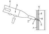
図1を参照するに、骨固定システム10は、プレート14と、このプレート14を骨26のような目標とする解剖学的部位に取り付けるように構成した1つ以上のファスナ18と、プレート14及びファスナ18を取り付けるのを促進する手術装置22とを有している。骨26は、骨断片部26A及び26Bのような2つ以上の骨折した骨断片部を有するか、又は骨固定処置を用いることにより治療可能であるその他の何らかの変形部を有する場合があることを理解すべきである。更に、目標とする解剖学的部位は、靭帯や軟組織又は硬組織構造部位のような骨以外の構造部位とすることができる。図示するように、プレート14は骨26上に配置し、手術装置22はプレート14上に配置してこのプレート14と骨26との何れか又は双方に穴を開け、ファスナ18を用いてプレート14を骨26に固定するようにしうる。1つ以上のファスナ18と手術装置22とを用いるプレート14の固定は、1つの装置を用いて実行しうる。例えば、穴を開け、ファスナ18を配置し、1つ以上のファスナ18でプレート14を骨26に固定するのに、1つのみの装置22を用いることができる。固定システム10の全体をキットとして販売するか、又はプレート14及び1つ以上のファスナ18をこれら自体キットとして販売することができることを理解すべきである。例えば、寸法及び形状の双方又は何れか一方が互いに異なる複数のファスナ18をキットとして提供することができる。
Referring to FIG. 1, the
上述したことに代え、又は上述したことに加え、寸法及び形状の双方又は何れか一方が互いに異なる複数のプレート14をキットとして提供することができる。更にこれに代え、又はこれに加え、寸法及び形状の双方又は何れか一方が互いに同じ又は異なる複数のファスナ18及び複数のプレート14の組み合わせを、これのみで又は手術装置22と組み合わせてキットとして提供することができる。更に、ファスナ18をピンとして示してあるが、これに代えファスナを、ねじ山面を有するねじ、平滑面又は歯付面を有する釘、ボルト、又は骨プレート14を下部の骨26に固定するように構成されたその他の任意の固定装置として提供することができる。
Instead of the above, or in addition to the above, a plurality of
図1に示すように、手術装置22は、ハンドピース82と、このハンドピース82にコード90により接続された制御ユニット86とを有している。この制御ユニットは、プレート14及び骨26内に穴をあけるように構成したカッティング機構46と、ファスナ18を加熱して軟化させ、これによりプレート14を骨26に取り付けるように構成したエネルギー源70とを制御する。カッティング機構46は第1のレーザ94と洗浄システム98とを有し、エネルギー源70は第2のレーザ102を有することができる。第1のレーザ94と、洗浄システム98と、第2のレーザ102とは制御ユニット86内に配置され、コード90を経て手術装置22のハンドピース82に提供される。
As shown in FIG. 1, the
プレート14は、骨断片部に連結しうる耐力構造を提供する。プレート14は、ポリマー材料から形成するのが好ましい。例えば、プレート14を、ポリ‐アルファ‐ヒドロキシエステル、ポリオルトエステル、ポリ無水物、ポリホスファゼン、ポリ(プロピレンフマレート)、ポリエステルアミド、ポリエチレンフマレート、ポリラクチド、ポリグリコライド、ポリカプロラクトン、トリメチレンカーボネート、ポリジオキサノン、ポリハイドロブチレートや、これらのコポリマーや、これらの混合物から形成しうる。プレート14には、電磁放射吸収特性を含めることもできる。プレート14には例えば、クロロフィル、カーボンブラック、酸化鉄、グラファイト、フルオレセイン、メチレンブルー、インドシアニングリーン、エオシン;エオシンY(514nm)、エチルエオシン(532nm)、アクリダイン、アクリダインオレンジ、銅フタロシアニン、クロム‐コバルト‐酸化アルミニウム、クエン酸鉄アンモニウム、ピロガロール、ログウッドエキス、銅クロロフィリン、D&CブルーNo.9、D&CグリーンNo.5、[フタロシアニネート(2−)]銅、D&CブルーNo.2、D&CブルーNo.6、D&CグリーンNo.6、D&CバイオレットNo.2及びD&CイエローNo.10のような添加剤を含め、これによりプレート14が第2のレーザ102からの熱のようなエネルギーを吸収するようにすることができる。動作に当っては、電磁放射吸収特性を有するプレート14の部分がレーザビームを吸収して変形し、これにより骨26に対するプレート14の固定に寄与する。他の実施例では、電磁放射吸収要素に磁性ナノ粒子を含めることができ、第2のレーザ102は、20kHz〜10GHzの範囲の電磁信号を放出する電磁気トランスミッタに代えることができる。或いはまた、ファスナ/プレートを溶融させるのに、超音波振動、通常の通りに加熱した金属ボルト又は加熱した空気流を用いることができる。
The
更に、プレート14は穴を予め開けることなしに提供し、従って、1つ以上のファスナ18を挿入するための目標位置を規定するこのプレートの長手方向に沿う両対向エッジ間で、このプレートが連続する表面を規定するようにすることができる。プレートの取り付け中に、手術装置22のカッティング機構を用いてプレート14に穴を開けることができる。しかし、プレート14は、連続表面を規定するプレートに限定されるものではなく、穴を予め開けたプレートを提供することができる。更に、当業者にとって明らかなように、プレート14及び穴は種々の形状及び寸法とすることができる。
In addition, the
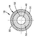
図2A〜2Cに示すように、各手術用ファスナ18は長手方向Lに長くなっており、遠位端部D及び近位端部Pを規定している。各手術用ファスナ18は更に、ファスナ18の中心軸線を規定しうる長手軸線49に沿って長手方向Lで主体部44を貫通している孔48を有している。従って、主体部44は、この主体部44の外面55を規定する外形D1と、この主体部44の内面52を規定する内形D2とを有する管状となっている。図示するように、主体部44は、内面52に隣接する第1の部分、すなわちコア部分50と、外面55に隣接する第2の部分、すなわち周囲部分51とに分離させることができる。
As shown in FIGS. 2A-2C, each
ファスナ18の主体部44は、熱可塑性材料、例えば、ポリ‐アルファ‐ヒドロキシエステル、ポリオルトエステル、ポリ無水物、ポリホスファゼン、ポリ(プロピレンフマレート)、ポリエステルアミド、ポリエチレンフマレート、ポリラクチド、ポリグリコライド、ポリカプロラクトン、トリメチレンカーボネート、ポリジオキサノン、ポリハイドロブチレートや、これらのコポリマーや、これらの混合物から形成する。外面55に隣接する主体部44の周囲部分51は、電磁放射吸収特性を有するのに充分に着色されているようにし、一方、内面52に隣接する主体部44のコア部分50は、エネルギー源により与えられる電磁放射に対し透過性とする。着色した周囲部分51には、例えば、クロロフィル、カーボンブラック、酸化鉄、グラファイト、フルオレセイン、メチレンブルー、インドシアニングリーン、エオシン;エオシンY(514nm)、エチルエオシン(532nm)、アクリダイン、アクリダインオレンジ、銅フタロシアニン、クロム‐コバルト‐酸化アルミニウム、クエン酸鉄アンモニウム、ピロガロール、ログウッドエキス、銅クロロフィリン、D&CブルーNo.9、D&CグリーンNo.5、[フタロシアニネート(2−)]銅、D&CブルーNo.2、D&CブルーNo.6、D&CグリーンNo.6、D&CバイオレットNo.2及びD&CイエローNo.10のような添加剤を含め、これにより周囲部分51が第2のレーザ102により生ぜしめられる電磁放射を吸収するようにすることができる。
The
周囲部分51の熱可塑性材料は、第2のレーザ102のエネルギーを吸収することにより加熱され、軟化する。すなわち、ファスナ18の軟化は、第2のレーザ102から生じる放射を吸収することにより、ファスナ18を変形させる点まで発生される熱により生じ。特に、添加剤が、ある場合には熱可塑性材料自体がレーザを吸収して加熱し、これにより熱可塑性材料を軟化させる。軟化した熱可塑性材料は、変形して骨組織の空洞内に膨張し、これによりファスナ18及びプレート14を骨26に固定することができる。周囲部分51は、照射されたエネルギーをコア部分50の少なくとも2倍吸収しうる。しかし、代表的には、周囲部分51はコア部分50に比べて5〜1000倍以上のエネルギーを吸収する。換言すれば、コア部分50は0〜10%を吸収するが、周囲部分51は50〜100%のエネルギーを吸収しうる。周囲部分51の厚さは、0.1mmよりも厚くするか、又は外径D1の1〜20%にするか、又はこれらの双方を満足するようにするのが好ましい。周囲部分51は、第2のレーザ102を吸収しうる熱可塑性材料に限定されず、他の材料を用いることができることを理解すべきである。周囲部分51には例えば、磁性ナノ粒子を含め、レーザを、1kHz〜1MHz、又は100kHz〜100GHzの範囲の電磁信号を放出する電磁気トランスミッタに代えることができる。
The thermoplastic material of the surrounding
電磁放射に対し透過性であるファスナ18のコア部分50は全く温まらないようにするか又はほんの僅かだけ温まるようにして、その機械的強度を保つように構成することができる。同時に、コア部分50は光学素子として作用し、エネルギーを骨プレート14内に前進させるようにすることができる。次に、ファスナ18を、これよりも小さくしうる予め形成した穴内に押し込み、その後、温められて軟化したポリマーを骨の空間内に押し込む。エネルギー源を止めた後、ポリマー(熱可塑性材料)を冷却させて迅速に(1〜2分よりも短い時間で)硬化させ、ファスナ18と骨及び骨プレート14の双方又は何れか一方との間の機械的な相互嵌合を達成させる。
The
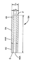
コア部分50と周囲部分51とは互いに結合される個別部品とし、周囲部分51を、例えば図2Cに示すような、電磁放射吸収特性を有するコーティング層とすることができ、或いはこれらコア部分50と周囲部分51とを、周囲部分51が発色団(すなわち、色又は色素)を有している図2Bに示しているような一体の、従って、1つの部品とすることができる。更に、ある実施例では、周囲部分51を、可変吸収係数“a”を有する領域とすることができる。何れの場合でも、周囲部分51は、第1のレーザ94に曝されるのに応答してこの周辺部分51が変形するのに充分な電磁放射吸収特性を有するものであり、コア部分50の熱可塑性材料の領域が有する第2のレーザに対する透過性を、周囲部分51が有する透過性よりも大きくする。従って、着色していない内側のコア部分50は、周囲部分51を変形する第1のレーザ94に曝された場合にその構造上の完全性を殆ど保つものである。
The
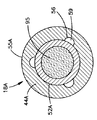
他の実施例では、図3A〜3Dに示すように、ファスナ18Aが、長手軸線49とほぼ平行に延在する方向に対して整列された第1及び第2部分を有する主体部44Aを具えている。ファスナ18Aのこの主体部44Aは、図3Bに示すように、第1の軸線方向部分64と、この第1の軸線方向部分64に対して先端に配置された第2の軸線方向部分60とを有することができる。第1の軸線方向部分64は電磁放射に対し透過性とすることができるとともに、第2の軸線方向部分60は電磁放射を吸収するように構成することができる。
In another embodiment, as shown in FIGS. 3A-3D,
ファスナ18の場合と同様に、ファスナ18Aを熱可塑性材料から形成しうる。例えば、各ファスナ18Aを、ポリ‐アルファ‐ヒドロキシエステル、ポリオルトエステル、ポリ無水物、ポリホスファゼン、ポリ(プロピレンフマレート)、ポリエステルアミド、ポリエチレンフマレート、ポリラクチド、ポリグリコライド、ポリカプロラクトン、トリメチレンカーボネート、ポリジオキサノン、ポリハイドロブチレートや、これらのコポリマーや、これらの混合物から形成しうる。第2の軸線方向部分60はその体積全体に亘って着色するとともに、例えばレーザ102により生ぜしめられるエネルギーをこの第2の軸線方向部分が吸収するようにする電磁放射吸収特性を当該第2の軸線方向部分60が有するようにし、第1の軸線方向部分64はレーザ102により生ぜしめられるエネルギーに対し透過性とする。着色した第2の軸線方向部分60には、例えば、クロロフィル、カーボンブラック、酸化鉄、グラファイト、フルオレセイン、メチレンブルー、インドシアニングリーン、エオシン;エオシンY(514nm)、エチルエオシン(532nm)、アクリダイン、アクリダインオレンジ、銅フタロシアニン、クロム‐コバルト‐酸化アルミニウム、クエン酸鉄アンモニウム、ピロガロール、ログウッドエキス、銅クロロフィリン、D&CブルーNo.9、D&CグリーンNo.5、[フタロシアニネート(2−)]銅、D&CブルーNo.2、D&CブルーNo.6、D&CグリーンNo.6、D&CバイオレットNo.2及びD&CイエローNo.10のような添加剤を含め、これにより第1の軸線方向部分64が第2のレーザ102により生ぜしめられる電磁放射を吸収するようにすることができる。動作に当っては、ファスナ18Aの第2の軸線方向部分60の体積全体の熱可塑性材料がレーザビームを吸収して変形し、これによりプレート14を骨26に固定させる。他の実施例では、第2の軸線方向部分60が磁性ナノ粒子を有するようにでき、第1のレーザは、20kHz〜10GHzの範囲の電磁信号を放出する電磁気トランスミッタに代えることができる。
As with the
第1の軸線方向部分64と第2の軸線方向部分60とは、互いに結合される個別部品とすることができ、或いはこれら第1の軸線方向部分64と第2の軸線方向部分60とを、一体の、従って、1つの部品とし、第2の軸線方向部分60が電磁放射吸収特性を有するコーティング層を具えるようにしうる。何れの場合でも、第2の軸線方向部分60は、レーザ102のようなエネルギー源に曝されるのに応答してこの第2の軸線方向部分60が変形するのに充分な電磁放射吸収特性を有するものであり、第1の軸線方向部分64の熱可塑性材料が有するレーザビーム102に対する透過性を、第2の軸線方向部分60が有する透過性よりも大きくし、着色していない第1の軸線方向部分64が、第2の軸線方向部分60を変形するレーザビーム102に曝された場合にその構造上の完全性を殆ど保つようにする。第2の軸線方向部分60は主体部44の遠位端部“D”に配置されているように図3Bに示してあり、第1の軸線方向部分64は第2の軸線方向部分60に比べて近位位置に配置されているものとして示してある。着色した第2の軸線方向部分60は、長手方向に沿うファスナ18Aの全長の10〜80%とすることができる。
The first
図3A〜3Dに示すように、ファスナには洗浄路59を設けることができ、これら洗浄路は図3A及び3Dに示す凹所56又はクローズド通路57として構成することができる。図3A及び3Bに示すように、ファスナ18Aには、長手軸線49に沿って伸長された中空の円筒体44Aが設けられている。この主体部44Aは、外径D1を規定する外面55Aを有している。図示するように、各ファスナ18Aは、長手軸線49の方向で主体部44Aを貫通する孔48Aを有する。この孔48Aは、図示するように、主体部44Aの内面52Aを規定する内径D2を有する。主体部44Aには更に、近位端部Pから遠位端部Dまで孔48Aの全長に沿って内面52A内に延在する凹所56として構成した複数の洗浄路59が規定されている。主体部44Aは、円周方向に等間隔に離間した(すなわち、横断面で見た際に120°に配置された)3つの凹所56を規定するものとして示してあるが、この主体部44Aには、所望に応じこの主体部44Aを中心とし円周方向で所望通りに離間した任意の個数の凹所56を設けることができる。図3Aに示すように、各凹所56は、横断面において半円形にすることができ、洗浄液を収容して流すように構成しうる。各凹所56は、約0.1mm〜約0.5mmの半径を有しうる。これらの凹所56は放射状に互いに離間させて配置し、例えば、洗浄液を3つの洗浄路59のうちの2つの洗浄路を介して注入するとともに3つの洗浄路59のうちの1つの洗浄路を介して吸出すようにする複数の洗浄路を得る。しかし、凹所56は半円に限定されるものではなく、洗浄液を入れることができ如何なる形状にすることもできる。
As shown in FIGS. 3A-3D, the fasteners can be provided with cleaning
他の実施例では、図4Dに示すように、ファスナにはクローズド通路57である洗浄路59を設けることができる。図示するように、ファスナ18Bは、管状主体部44Bと、この管状主体部44Bを貫通する孔48Bと、管状主体部44Bの内面52B及び外面55B間で、孔48Bには連通しないようにこの管状主体部44Bを貫通して延在するとともに円周方向で等間隔に離間された3つのクローズド通路57とを有している。主体部44Bは円周方向で等間隔に離間された3つの通路57を規定するように示してあるが、所望に応じこの主体部44Bを中心とする円周方向で所望通りに離間した任意の個数の通路57を設けることができる。
In other embodiments, as shown in FIG. 4D, the fastener may be provided with a cleaning
ファスナ18、18A及び18Bは種々の寸法で設けることができる。例えば、各ファスナの外径D1は1.5mmと5mmの間とすることができ、ファスナの孔の直径D2は約0.4mm〜3mmとすることができる。更に、長手軸線49に沿って延在するファスナの長さTは約3mmと約20mmの間の長さとすることができる。これらの寸法は例示目的にすぎず、ファスナはプレート14をその下側の骨26に固定しうる如何なる寸法にもすることができることを理解すべきである。
ファスナのポリマー内には種々の方法を用いて色材又は着色剤粒子を取り込むことができる。例えば、色材含有ポリマー層又はインプラント要素は、いわゆる2構成要素射出成形処理で形成しうる。この場合、ファスナの未着色部分を第1段階で射出成形し、射出成形金型内のキャビティを修正した後、色材含有部分を第2段階で射出成形する。 Colorant or colorant particles can be incorporated into the fastener polymer using a variety of methods. For example, the colorant-containing polymer layer or implant element can be formed by a so-called two-component injection molding process. In this case, the uncolored portion of the fastener is injection-molded in the first stage, the cavity in the injection mold is corrected, and then the coloring material-containing portion is injection-molded in the second stage.
色材含有ポリマーの層は、色材及びポリマー含有溶液を被着して乾燥させることにより得ることもできる。この場合、キャンドル・ドゥローイング(candle−drawing)処理(浸漬被覆処理)に類似する、色材及びポリマー含有溶液の堆積及び乾燥処理、又は吹き付け処理により色材含有ポリマーの層を得ることができる。この最初の堆積処理を用いることにより、極めて薄肉(マイクロメートル厚)の層から極めて厚肉(サブミリメートル又はミリメートルレンジ)の層まで達成しうる。 The layer of the colorant-containing polymer can also be obtained by applying the colorant and the polymer-containing solution and drying. In this case, a layer of a colorant-containing polymer can be obtained by a deposition and drying process of a colorant and a polymer-containing solution, or a spraying process similar to a candle-drawing process (dip coating process). By using this initial deposition process, one can achieve from a very thin (micrometer thick) layer to a very thick (submillimeter or millimeter range) layer.
着色層は、着色剤粒子含有懸濁液又は溶液を被着して乾燥させることによっても達成しうる。この場合、最初に色材含有粒子を加熱することによりコーティングを達成する。次に、この加熱された粒子をファスナの未着色部分の表面上に噴射させることにより、粒子をファスナの未着色部分のポリマーと融合させ、表面上に固着させる。 The colored layer can also be achieved by applying a colorant particle-containing suspension or solution and drying it. In this case, the coating is achieved by first heating the colorant-containing particles. The heated particles are then jetted onto the surface of the uncolored portion of the fastener, thereby fusing the particles with the polymer of the uncolored portion of the fastener and anchoring onto the surface.
又、セラミック又はその他の非熱感応性粒子がポリマーと局部的に融合して表面内に固着しうる加熱状態で、これら粒子をポリマー表面上に噴射させることにより、これら粒子を表面に被着させることもできる。その一例は、股関節プロテーゼに例えば、リン酸カルシウム粒子を被覆するプラズマ吹き付け処理により得られる。適切な基板が存在する場合には、化学蒸着(CVD)又は物理蒸着(PVD)のような処理を用いることも考えられる。 Also, these particles are deposited on the surface by spraying them onto the polymer surface in a heated state where ceramic or other non-heat sensitive particles can locally fuse with the polymer and adhere to the surface. You can also. One example is obtained by a plasma spraying process in which a hip joint prosthesis is coated with, for example, calcium phosphate particles. If a suitable substrate is present, a process such as chemical vapor deposition (CVD) or physical vapor deposition (PVD) may be used.
各ファスナは、図4A〜4Cに示す手術装置22を用いてプレート14及び骨26に対し配置して固定させることができる。図示するように、手術装置22はハンドピース82と、制御ユニット86と、ハンドピース82を制御ユニット86に接続しているコード90とを有している。この手術装置22はカッティング機構46と、エネルギー源70との双方を設けるように構成された処理装置である。図示の実施例では、カッティング機構は第1のレーザ94と、第1の光導波路95に接続された洗浄体供給源98とを有しており、エネルギー源70は第2の光導波路103に接続された第2のレーザ102を有している。第1のレーザ94と洗浄体供給源98とはプレート14又は骨26又はその双方に孔を開けるように構成することができ、第2のレーザ102はファスナ18、18A及び18Bのうちの何れか1つ又は複数のファスナの第2の軸線方向部分60又は周囲部分51を加熱して変形させるように構成しうる。洗浄体供給源98は、冷却液を供給するとともにカッティング個所から屑を除去するように構成されている。光導波路95及び103は、エネルギー源からファスナに電磁放射を送給するのに用いる、例えば、グラスファイバケーブル又は反射(リフレクティング)ホース(例えば、ナノチューブでもよい)のような可撓性の又は剛性の光学的な光伝達構造体とすることができる。一方、ファスナ自体を光ファイバ及び光拡散器として作用させることができる。光は、ファスナ内に入った後、殆どポリマーの表面でこのポリマーを軟化させる点に到達するまでこのファスナの第1の部分を通過する。一方、光を光ファイバに通してファスナの所望点まで到達させるために、ファスナが実際に光を伝達し、例えば、光をピンの先端まで到達させ、この先端で分散させ、例えば、拡散によりファスナの表面に到達させるようにする。
Each fastener can be positioned and secured to the
一実施例では、第1のレーザ94を3μm赤外線レーザとし、洗浄体供給源98は水のような液体を用い、第2のレーザは800nm赤外線レーザとする。しかし、手術装置22は、3μm赤外線レーザ及び水供給源を有するカッティング機構46に限定されず、エネルギー源も800nm赤外線レーザを有するものに限定されないことを理解すべきである。例えば、カッティング機構46を、洗浄体供給源と組み合わせた10μm赤外線CO2レーザとするか、又は洗浄体供給源と組み合わせた2.8μmエルビウムYAGレーザとすることもできる。同様に、第2のレーザを、400nm〜1800nmの範囲内の波長を有するレーザとするか、又はこれを、20kHz〜10GHzの範囲内の電磁気トランスミッタに代えることができ、又は双方の赤外線レーザを、
(i)プレート14を貫通して骨構造体26をカッティングしうるとともに、
(ii)ファスナ18を加熱し、これによりこのファスナ18を軟化させうる
超音波源に代えることができる。
In one embodiment, the
(I) the
(Ii) The
制御ユニット86は、第1のレーザ94と、洗浄体供給源98と、第2のレーザ102との各々を有する。この制御ユニット86は、骨固定システムの動作を決定するために、ユーザにより制御される設定手段を有しうる。例えば、ユーザは最初に第1のレーザ94及び洗浄体供給源98を同時に制御し、プレート14及び骨26に穴を開け(カッティングを行い)、次に中間処置で第2のレーザを制御してファスナ18を変形させるように制御ユニット86を設定することができる。
The
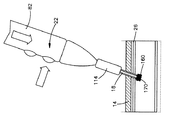
図1及び図4A〜4Cに示すように、ハンドピース82は細長状の本体110を具えており、この本体110はその遠位端部に先端部114を有するとともに、その近位端部に本体110をコード90に接続するための接続部118を有している。細長状の本体110は一般に、図4Cに示すように第1の導波路95及び第2の導波路103と、洗浄体チューブ126a及び126bとの双方又は何れか一方を制御するように構成した管状の構造体である。第1の光導波路95及び第2の光導波路103は、第1のレーザ94及び第2のレーザ102のビームを制御ユニット86から本体110を経て先端部114に伝達するように構成した光ファイバとすることができる。同様に、洗浄体チューブ126は、洗浄液を制御ユニット86から本体110を通って先端部114に送給するとともに、洗浄液を逆方向に吸出すように構成しており、従って、洗浄チューブと称することもできる。ファスナの遠位端部に最も近いファイバ先端部130は第1のレーザ94のビームを所望通りに分散させて、プレート14及び骨26内に開ける穴が、ファスナが通る直径を有するようにする。ファイバ先端部130を装置22内に数ミリメートルだけ戻し、ファスナの第2の軸線方向部分60を骨構造体26の内部に圧入するようにしうる。例えば、ユーザによりファスナが下方に押されると、ファイバ先端部130が手に対して近接的に並進運動するか、又はファスナ18Aの第2の軸線方向部分60が圧縮するか又はさもなければ変形するように部分的に圧縮することにより、ファイバ先端部130が近接的に後退しうる。
As shown in FIGS. 1 and 4A-4C, the
図3Cをも参照するに、第1の光導波路95は、ファスナ18の主体部44の孔48を貫通するように構成されている。特に、第1の光導波路95はその直径を孔48の直径にほぼ等しく規定している。従って、ファスナ18の孔48は、第1のレーザ94のビームを案内する第1の光導波路95を、この第1の光導波路95と孔48の内面52との間に隙間が殆どないように収容する寸法となっている。その結果、第1の光導波路95は、各凹所56の内側の径方向端部を殆ど封止し、ファスナ18の長手方向に沿って延在する複数の洗浄路59を規定するようになっている。
Referring also to FIG. 3C, the first
図4Cは、図2Aに示すファスナ18や、図3A及び3Dに示す洗浄路59を有するファスナ18A及び18Bのようなファスナに対し用いられるように構成された先端部114を示している。この先端部114は、ファスナを把持するか又は保持するように構成されている。ファスナ18の近位端部Pは、例えば、先端部114内の対応する孔140に圧入する寸法とした円筒部分として構成しうる取り付け部分45を有するようにしうる。図示するように、この先端部114は、この先端部114の壁部146からこの先端部の遠位端部の方向に延在する経路144と、この経路144と整列して先端部114の遠位端部からこれに近接して延在する孔140とを有している。孔140は、その直径を経路144の直径よりも大きく規定し、先端部114が孔140と経路144との間の界面に座部148を形成する。この界面は、ファスナ18が孔140内に完全に挿入されるか又は配置されると、経路144の遠位端部でファスナ18に接するとともにこのファスナ18を支持する。経路144は洗浄液を注入させるための注入セグメント145aとこの注入液を屑と一緒に吸出すようにする吸出セグメント145bとに分かれている。ハンドピースの本体110は更に、先端部114内に延在する第1のポート150及び第2のポート151を有している。これらのポート150及び151はそれぞれ、これらの近位端部においてこれらに洗浄チューブ126a及び126bを結合させるための結合部154と、遠位端部において開口部158とを有している。第1のポート150及び第2のポート151の開口部158は、経路144内に延在し、経路144を第1のポート150及び第2のポート151の結合部154に流体連結させる。
FIG. 4C shows a
孔140は、上述したようにファスナ18A又は18Bのようなファスナを入れて保持する寸法であり、経路144は、ポートの開口部158から、凹所56又はクローズド通路57としうるファスナの2つの洗浄路59へ洗浄体供給源98の洗浄液を案内するとともに、この洗浄液及び屑をファスナ18の第3の洗浄路59を経て吸出すように構成されている。
The
第1の洗浄チューブ126aは、第1のポート150の結合部154に連結されており、洗浄体供給源98の洗浄液は第1の洗浄チューブ126aを通り第1のポート150を経て経路144の注入セグメント145a内に入り、且つファスナの2つの洗浄路59を通って進行する。第2の洗浄チューブ126bは第2のポート151の結合部154に連結されており、屑を有する洗浄液を、ファスナ18の第3の洗浄路59を経て経路144の吸出セグメント145b内に且つ第2のポート151を経て第2の洗浄チューブ126b内に吸出すことができる。
The
第1のレーザ94のビームと洗浄体供給源98の洗浄液とは同時に、ファスナ18Aをその長手方向で通過し、このファスナ18Aの遠位端部Dを出て、これによりプレート14と骨26との双方又は何れか一方に穴をあけるようにすることができる。図示するように、第2のレーザ102のビームはファスナ18Aの前方壁部、すなわち近位壁部160に案内することができる。この第2のレーザ102を動作させると、光がファスナ18Aの透明な第1の軸線方向部分64通過し、レーザ吸収性の第2の軸線方向部分60により吸収される。或いはまた、図2A〜2Cによるファスナ18を用いると、光がコア部分50における熱可塑性材料を通過し、ファスナ18の外面55に隣接する周囲部分51のレーザ吸収性着色熱可塑性材料により且つプレート14の隣接部分により吸収される。
The beam of the
先端部114は、ファスナ18、18A又は18Bの何れかのようなファスナと、骨26に適切に穴を開けるように構成したファイバ先端部130(このファイバ先端部130は、レーザビームを分散させて、実際にファスナを嵌合させるのに充分でファイバ先端部よりも大きい大きさの穴が開けられるような形状としうることに注意されたい)とをもって構成しうる殺菌した(無菌の)使い捨て部分とすることができる。この使い捨て部分は選択的に、本体110の遠位端部に取り付けたり、この遠位端部から取り外したりするように構成しうる。又、この使い捨て部分は、加圧滅菌器(オートクレーブ)に入れることができる材料から形成することもできる。
The
図4Dは、図2A〜2Cに示すようなファスナ18に対し用いるように構成した先端部114の他の実施例を示す。図4Dによる先端部114の実施例は、この先端部114にスリーブ156か固定され、このスリーブが経路144と流体連結されているという点でのみ、図4Cの実施例と相違している。スリーブ156は、ファスナ18の孔48内に挿入し、第1の光導波路95を囲むようにすることができる。2つ以上の孔157は、これらの周囲方向で互いに等しい距離だけ離間されるとともに、洗浄体供給源98の洗浄液を経路144から先端部130に案内するのに適するように配置されている。経路144は、洗浄液を注入する注入セグメント145aと、この注入液を屑と一緒に吸出す吸出セグメント145bとに分離されている。注入セグメント145aは、洗浄体供給源98の洗浄液をポート開口158から、ファスナ18の孔48内に挿入されたスリーブ156内の2つ以上の孔157を経て案内するように構成されており、吸出セグメント145bは、洗浄液と屑とを、スリーブ156内の1つ以上の孔157を経て吸出すように構成されている。
FIG. 4D shows another embodiment of a
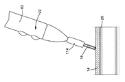
図5A〜5Dを参照するに、動作に当っては、手術装置22をプレート14及びファスナ18(又は18A又は18B)に簡単且つ有効に添えることができる。図5Aに示すように、ファスナ18が部分的にハンドピース82の先端部114の末梢に伸びるようにこのファスナ18を先端部114内に配置し、プレート14を骨26の骨折領域上に配置する。次に、ハンドピース82をファスナ18と一緒に、プレート14の表面上にこのプレート14に対し90°の角度で又は所望に応じこの90°に対しオフセットさせて配置する。ハンドピース82が配置されると、制御ユニット86を動作させて第1のレーザ94のビーム及び洗浄体供給源98が、プレート14を通るとともに所望に応じ骨26内に至る穴55を開けるようにしうる。図5Bに示す状態で、第1のレーザ94及び洗浄体供給源98の洗浄液がファスナ18の孔48を通過してこのファスナ18の遠位端部から出る。穴55が開けられると、ハンドピース82を、従って、ファスナ18を、時間をかけて徐々に穴内に押し込むことができる。
5A-5D, in operation, the
穴が所望の深さに達し、ファスナ18がこの穴内に適切に配置されると、第1のレーザ94及び洗浄体供給源98を不作動とするとともに、第2のレーザ102を作動させ、これによりファスナ18の一部を変形させるように制御ユニット86を切換えることができる。図5Cに示すように、第2のレーザ102のビームがファスナ18と、プレート14及びファスナ18間の界面とを軟化させるとともに変形させる。装置22を前記の長手軸線49の方向で穴55内に徐々に押し込むことにより、ファスナ18の一部を変形させるとともに、この一部の外径を穴55の径よりも大きくする。従って、ファスナ18はリベットに変形し、このリベットによりプレート14を骨26に結合させる。
When the hole reaches the desired depth and the
上述した骨固定処置は、骨折により分離した骨26の1つ以上の骨断片部に骨プレート14を固定するのに実行しうる。例えば、骨プレート14を一か所以上の骨折部位上に配置し、1つ以上のファスナによりこのプレート14を上述したように各骨断片部に結合させることができる。
The bone fixation procedure described above can be performed to fix the
図5Dに示すように、プレート14及びファスナ18をそのまま残した状態に維持して、装置22を取り外すことができる。これらのプレート14及びファスナ18は再吸収可能な材料から形成しうる。
(その他の実施形態)
1. 請求項3に記載の手術用ファスナにおいて、前記主体部の前記第1の部分は、前記内面を規定するコア部分であり、前記第2の部分は、前記外面を規定する周囲部分である手術用ファスナとすることもできる。
2. 請求項4に記載の手術用ファスナにおいて、前記方向は、前記長手軸線に対しほぼ垂直である手術用ファスナとすることもできる。
3. 請求項5に記載の手術用ファスナにおいて、前記第1の部分及び前記第2の部分は、前記長手方向に対してほぼ平行に延在する方向に対して整列されている手術用ファスナとすることもできる。
4. 請求項1に記載の手術用ファスナにおいて、前記電磁放射は、100kHz〜100GHzの範囲内の周波数を有している手術用ファスナとすることもできる。
5. 請求項9に記載の手術用ファスナにおいて、前記色が400nmと1800nmとの間の波長を有している手術用ファスナとすることもできる。
6. 請求項9に記載の手術用ファスナにおいて、前記第2の部分の前記色が、D&CブルーNo.9とインドシアニングリーンとのうちの少なくとも一方を有している手術用ファスナとすることもできる。
7. 請求項11に記載の手術用ファスナにおいて、前記洗浄路は、前記孔に対し開口している手術用ファスナとすることもできる。
8. 請求項11に記載の手術用ファスナにおいて、前記洗浄路は、前記主体部の前記第1の部分内に延在している手術用ファスナとすることもできる。また、このようにした手術用ファスナにおいて、前記洗浄路は更に、前記主体部の前記第2の部分内に延在している手術用ファスナとすることもできる。
9. 請求項3に記載の手術用ファスナにおいて、この手術用ファスナは更に、前記内面と前記外面との間において前記長手軸線の方向で前記主体部を貫通して延在する少なくとも1つのクローズド通路を有し、このクローズド通路は洗浄液を受けて流すように構成されている手術用ファスナとすることもできる。また、このようにした手術用ファスナにおいて、前記クローズド通路は、前記主体部の前記第1の部分を貫通して延在している手術用ファスナとすることもできるし、あるいは、このようにした手術用ファスナにおいて、前記クローズド通路は、前記主体部の前記第2の部分を貫通して延在している手術用ファスナとすることもできる。
10. 請求項1に記載の手術用ファスナにおいて、前記主体部は、ポリ‐アルファ‐ヒドロキシエステル、ポリオルトエステル、ポリ無水物、ポリホスファゼン、ポリ(プロピレンフマレート)、ポリエステルアミド、ポリエチレンフマレート、ポリラクチド、ポリグリコライド、ポリカプロラクトン、トリメチレンカーボネート、ポリジオキサノン、ポリハイドロブチレート、これらのコポリマー、これらの混合物のうちの少なくとも1つを有する熱可塑性材料から形成されている手術用ファスナとすることもできる。
11. 請求項12に記載の手術装置において、前記ハンドピースが更に、前記本体から延在している先端部であって前記ファスナを支持する当該先端部を具えている手術装置とすることもできる。
12. 請求項12に記載の手術装置において、この手術装置が更に、前記カッティング機構及び前記エネルギー源を制御するように構成されている制御ユニットを具えている手術装置とすることもできる。また、このようにした手術装置において、この手術装置が更に、前記制御ユニットを前記ハンドピースに結合するコードを有している手術装置とすることもできる。
13. 請求項12に記載の手術装置において、前記カッティング機構が第1のレーザを有している手術装置とすることもできる。また、このようにした手術装置において、前記第1のレーザを、3μm赤外線レーザ、又は10μm赤外線CO 2 レーザ、又は2.8μmエルビウムYAGレーザとした手術装置とすることもできる。さらに、このようにした手術装置において、前記カッティング機構が更に洗浄体供給源を具えている手術装置とすることもできるし、さらに加えて、前記洗浄体供給源が水を有している手術装置とすることもできる。
14. 請求項12に記載の手術装置において、前記エネルギー源が800nmレーザを有している手術装置とすることもできる。
15. 請求項12に記載の手術装置において、前記エネルギー源が超音波源である手術装置とすることもできる。
16. 請求項13に記載のキットにおいて、前記ファスナの前記孔が内面を有し、この内面には前記孔の全長に亘って延在する少なくとも2つの凹所が規定されており、これらの凹所は、洗浄供給体を受けてこの洗浄供給体を、前記ファスナを経て案内するように構成されているキットとすることもできる。また、このようにしたキットにおいて、前記内面には3つの凹所が規定されているキットとすることもできる。
17. 請求項13に記載のキットにおいて、前記主体部の前記第2の部分は、レーザ吸収特性を有するコーティング層を具えているキットとすることもできる。
18. 請求項13に記載のキットにおいて、前記プレートが1つ以上の貫通穴を有しているキットとすることもできる。また、このようにしたキットにおいて、前記貫通穴のうちの少なくとも2つの貫通穴が互いに平行であるキットとすることもできる。
19. 請求項13に記載のキットにおいて、前記プレートが貫通穴を有していないキットとすることもできる。
20. 手術用ファスナを、目標とする解剖学的部位に固定するファスナ固定方法において、このファスナ固定方法が、
a)手術装置のカッティング機構を用いることにより、目標とする解剖学的部位に穴を開ける工程と、
b)前記カッティング機構により穴を開けている最中に、手術装置により支持されたファスナを、目標とする解剖学的部位の穴内に前進させる工程と、
c)手術装置のエネルギー源を動作させることにより前記ファスナを加熱して、このファスナの少なくとも一部分を軟化させる工程と、
d)前記ファスナが目標とする解剖学的部位に取り付けられている状態を保ったまま、手術装置を除去する工程と
を具えるファスナ固定方法とすることができる。また、このようにしたファスナ固定方法において、前記工程a)が、
a1)ポリマーを主体とする骨プレートを、目標とする解剖学的部位の上に配置する副工程と、
a2)手術装置の前記カッティング機構を用いることにより、前記骨プレートを貫通するとともに目標とする解剖学的部位内に到達する穴を開ける副工程と
を有しており、前記工程d)が、
前記ファスナ及び前記骨プレートが目標とする解剖学的部位に取り付けられている状態を保ったまま、手術装置を除去する工程
を有しているファスナ固定方法とすることもできる。さらに、このようにしたファスナ固定方法において、このファスナ固定方法が更に、
ファスナの少なくとも一部分を加熱して軟化させている際に、目標とする解剖学的部位内の前記孔内にファスナを圧入させる工程
を有しているファスナ固定方法とすることもできる。さらにまた、このようにしたファスナ固定方法において、前記ファスナを、これが少なくとも部分的に変形しうるようになる程度まで加熱するファスナ固定方法とすることもできる。
As shown in FIG. 5D, the
(Other embodiments)
1. The surgical fastener according to claim 3, wherein the first portion of the main body portion is a core portion that defines the inner surface, and the second portion is a peripheral portion that defines the outer surface. It can also be a fastener.
2. 5. The surgical fastener of claim 4, wherein the direction is a surgical fastener that is substantially perpendicular to the longitudinal axis.
3. The surgical fastener according to claim 5, wherein the first portion and the second portion are surgical fasteners aligned in a direction extending substantially parallel to the longitudinal direction. You can also.
4). The surgical fastener according to
5. The surgical fastener according to claim 9, wherein the color has a wavelength between 400 nm and 1800 nm.
6). The surgical fastener of claim 9, wherein the color of the second portion is D & C Blue No. 10. 9 and surgical fasteners having at least one of indocyanine green.
7). The surgical fastener according to claim 11, wherein the cleaning path may be a surgical fastener that is open to the hole.
8). The surgical fastener according to claim 11, wherein the cleaning path may be a surgical fastener extending in the first portion of the main body. In the surgical fastener thus configured, the cleaning path may be a surgical fastener extending in the second part of the main body.
9. 4. The surgical fastener of claim 3, further comprising at least one closed passage extending through the main body in the direction of the longitudinal axis between the inner surface and the outer surface. The closed passage can also be a surgical fastener configured to receive and flow cleaning fluid. Further, in the surgical fastener thus configured, the closed passage may be a surgical fastener extending through the first portion of the main body, or may be configured as described above. In the surgical fastener, the closed passage may be a surgical fastener extending through the second portion of the main body.
10. The surgical fastener according to
11. The surgical apparatus according to claim 12, wherein the handpiece further includes a distal end portion that extends from the main body and supports the fastener.
12 13. The surgical device according to claim 12, wherein the surgical device further comprises a control unit configured to control the cutting mechanism and the energy source. Moreover, in the surgical apparatus thus configured, the surgical apparatus may further be a surgical apparatus having a cord that couples the control unit to the handpiece.
13. The surgical apparatus according to claim 12, wherein the cutting mechanism includes a first laser. In the surgical apparatus thus configured, the first laser may be a surgical apparatus in which a 3 μm infrared laser, a 10 μm infrared CO 2 laser, or a 2.8 μm erbium YAG laser is used. Furthermore, in such a surgical apparatus, the cutting mechanism can be a surgical apparatus further provided with a cleaning body supply source, and in addition, the surgical apparatus in which the cleaning body supply source has water. It can also be.
14 The surgical apparatus according to claim 12, wherein the energy source includes an 800 nm laser.
15. The surgical apparatus according to claim 12, wherein the energy source is an ultrasonic source.
16. 14. The kit according to claim 13, wherein the hole of the fastener has an inner surface, the inner surface defining at least two recesses extending over the entire length of the hole, the recesses being The kit may be configured to receive the cleaning supply and guide the cleaning supply through the fastener. In addition, in the kit as described above, the inner surface may be a kit in which three recesses are defined.
17. 14. The kit according to claim 13, wherein the second portion of the main portion includes a coating layer having a laser absorption characteristic.
18. 14. The kit according to claim 13, wherein the plate has one or more through holes. Moreover, in such a kit, a kit in which at least two of the through holes are parallel to each other may be used.
19. The kit according to claim 13, wherein the plate does not have a through hole.
20. In a fastener fixing method for fixing a surgical fastener to a target anatomical site, the fastener fixing method includes:
a) drilling a hole in the targeted anatomical site by using the cutting mechanism of the surgical device;
b) advancing the fastener supported by the surgical device into the hole in the targeted anatomical site while the hole is being drilled by the cutting mechanism;
c) heating the fastener by operating an energy source of a surgical device to soften at least a portion of the fastener;
d) removing the surgical device while keeping the fastener attached to the targeted anatomical site;
A fastener fixing method comprising: In the fastener fixing method, the step a)
a1) a sub-step of placing a polymer-based bone plate over a target anatomical site;
a2) a sub-process of making a hole that penetrates the bone plate and reaches the target anatomical site by using the cutting mechanism of the surgical device;
And the step d) comprises
Removing the surgical device while keeping the fastener and the bone plate attached to the target anatomical site
The fastener fixing method can also be used. Furthermore, in this fastener fixing method, the fastener fixing method further includes:
A step of press-fitting the fastener into the hole in the target anatomical site while heating and softening at least a portion of the fastener;
The fastener fixing method can also be used. Furthermore, in the fastener fixing method described above, a fastener fixing method in which the fastener is heated to such an extent that it can be at least partially deformed can be used.
上述したことは説明の目的のためのことであり、本発明を上述したことに限定するものではない。好適な実施例又は好適な方法を参照して種々の実施例を説明したが、ここで用いた用語は説明上の例示の用語であり、本発明をこれらの用語の意味に限定するものではないことを理解すべきである。更に、上述した実施例は、特定な構造、方法及び実施例に対するものであり、本発明は上述した特定のものに限定されるものではない。更に、上述した実施例の何れにも、所望に応じ上述した他の実施例の何れの如何なる構造又は特徴をも含めることができる。本発明の内容に関連する当業者は、特許請求の範囲で規定される本発明の精神及び範囲を逸脱することなく、上述した本発明に対し種々の変形及び変更を達成することができるものである。 The foregoing is for illustrative purposes and is not intended to limit the invention to that described above. Although various embodiments have been described with reference to preferred embodiments or preferred methods, the terms used herein are illustrative terms and are not intended to limit the invention to the meaning of these terms. You should understand that. Further, the above-described embodiments are directed to specific structures, methods and embodiments, and the present invention is not limited to the specific embodiments described above. Further, any of the above-described embodiments can include any structure or feature of any of the other embodiments described above as desired. A person skilled in the art related to the contents of the present invention can achieve various modifications and changes to the present invention described above without departing from the spirit and scope of the present invention as defined in the claims. is there.
Claims (17)
前記手術用ファスナは主体部を有し、
前記主体部は、
近位端部と、長手軸線に沿ってこの近位端部から離間された遠位端部と、
外面と、
前記長手軸線に沿って前記近位端部から前記遠位端部まで前記主体部を完全に貫通するように延在している孔を規定する内面であって、前記孔はカッティング機構を収容し前記カッティング機構が前記主体部を通る前記長手軸線に沿って目標とする解剖学的な場所まで延在できるように構成されている、内面と、
前記近位端部から前記遠位端部へ延在し前記内面に隣接する第1の部分と、
前記遠位端部から前記近位端部へ延在し前記外面に隣接する第2の部分と、
を含み、
前記主体部の前記第1の部分が電磁放射に対し透過性であり、前記主体部の前記第2の部分が電磁放射に対し吸収性であり、この第2の部分は電磁放射を吸収すると軟化し、変形しうるようになっている手術用ファスナ。 Surgical fastener configured to be inserted into a distal tip of a handpiece, wherein the handpiece is connected to a control unit that supplies electromagnetic radiation as a laser emitted from the handpiece In fasteners,
The surgical fastener has a main portion;
The main body is
A proximal end and a distal end spaced from the proximal end along a longitudinal axis;
The outer surface,
An inner surface defining a hole extending completely through the main body from the proximal end to the distal end along the longitudinal axis, the hole accommodating a cutting mechanism. An inner surface configured to allow the cutting mechanism to extend along the longitudinal axis through the main body to a target anatomical location;
A first portion extending from the proximal end to the distal end and adjacent to the inner surface;
A second portion extending from the distal end to the proximal end and adjacent to the outer surface;
Including
The first portion of the main body portion is permeable to electromagnetic radiation, the second portion of the main body portion is absorbable to electromagnetic radiation, and the second portion softens when absorbing the electromagnetic radiation. Surgical fasteners that can be deformed.
ファスナ主体部とこのファスナ主体部を貫通して延在する孔とを含むファスナを支持するように構成した本体を有するハンドピースと、
前記ファスナが前記本体により支持された際に前記ファスナの前記孔を貫通して延在するように構成されているとともに、目標とする解剖学的部位内にカッティングを行うように構成されたカッティング機構と、
前記本体に結合されており、前記ファスナが前記本体により支持された際に前記ファスナの一部分を加熱するとともに軟化させるように構成されたエネルギー源とを具えている手術装置。 A surgical device configured to embed a surgical fastener in a target anatomical site, the surgical device comprising:
A handpiece having a body configured to support a fastener including a fastener main body and a hole extending through the fastener main body;
A cutting mechanism configured to extend through the hole of the fastener when the fastener is supported by the body and to perform cutting in a target anatomical region When,
A surgical device coupled to the body and comprising an energy source configured to heat and soften a portion of the fastener when the fastener is supported by the body.
少なくとも1つの請求項1〜13のいずれかに記載の手術用ファスナと
を具えるキット。 A bone plate having a thermoplastic material;
A kit comprising at least one surgical fastener according to any of claims 1-13.
Applications Claiming Priority (5)
| Application Number | Priority Date | Filing Date | Title |
|---|---|---|---|
| US32088310P | 2010-04-05 | 2010-04-05 | |
| US61/320,883 | 2010-04-05 | ||
| US41761410P | 2010-11-29 | 2010-11-29 | |
| US61/417,614 | 2010-11-29 | ||
| PCT/US2011/030855 WO2011126928A2 (en) | 2010-04-05 | 2011-04-01 | A bone fixation system |
Publications (2)
| Publication Number | Publication Date |
|---|---|
| JP2013523332A JP2013523332A (en) | 2013-06-17 |
| JP6038772B2 true JP6038772B2 (en) | 2016-12-07 |
Family
ID=44123483
Family Applications (1)
| Application Number | Title | Priority Date | Filing Date |
|---|---|---|---|
| JP2013503798A Expired - Fee Related JP6038772B2 (en) | 2010-04-05 | 2011-04-01 | Bone fixation system |
Country Status (10)
| Country | Link |
|---|---|
| US (3) | US9039683B2 (en) |
| EP (1) | EP2555693B1 (en) |
| JP (1) | JP6038772B2 (en) |
| KR (1) | KR101797449B1 (en) |
| CN (2) | CN108056809A (en) |
| BR (1) | BR112012024611A2 (en) |
| CA (1) | CA2788337C (en) |
| IN (1) | IN2012DN06584A (en) |
| TW (1) | TWI540998B (en) |
| WO (1) | WO2011126928A2 (en) |
Families Citing this family (8)
| Publication number | Priority date | Publication date | Assignee | Title |
|---|---|---|---|---|
| US8870871B2 (en) * | 2007-01-17 | 2014-10-28 | University Of Massachusetts Lowell | Biodegradable bone plates and bonding systems |
| US10842642B2 (en) | 2009-04-16 | 2020-11-24 | Nuvasive, Inc. | Methods and apparatus of performing spine surgery |
| US9351845B1 (en) | 2009-04-16 | 2016-05-31 | Nuvasive, Inc. | Method and apparatus for performing spine surgery |
| US9055987B2 (en) * | 2010-12-20 | 2015-06-16 | DePuy Synthes Products, Inc. | Kit for implanting heat deformable fixation elements of different sizes |
| BR112015022097A2 (en) * | 2013-03-12 | 2017-07-18 | Depuy Synthes Products Inc | fixture and laser fixture activation system and related system |
| US9247981B2 (en) | 2013-03-12 | 2016-02-02 | DePuy Synthes Products, Inc. | Laser type fixation member securement device and activation system, and related system and methods |
| EP3773298A1 (en) | 2018-04-03 | 2021-02-17 | Convergent Dental, Inc. | Laser system for surgical applications |
| US11980415B2 (en) * | 2020-12-11 | 2024-05-14 | Nuvasive, Inc. | Robotic surgery |
Family Cites Families (41)
| Publication number | Priority date | Publication date | Assignee | Title |
|---|---|---|---|---|
| US4784135A (en) | 1982-12-09 | 1988-11-15 | International Business Machines Corporation | Far ultraviolet surgical and dental procedures |
| ATE28974T1 (en) | 1982-12-09 | 1987-09-15 | Ibm | REMOVAL OF BIOLOGICAL MATERIAL BY PHOTOCHEMICAL DECOMPOSITION. |
| US4911712A (en) | 1988-04-14 | 1990-03-27 | Heraeus Lasersonics, Inc. | Medical laser probe |
| FR2640537B1 (en) | 1988-12-21 | 1992-02-21 | Levy Guy | INSTALLATION AND METHOD USING THE LASER EFFECT FOR CUTTING OR VAPORIZING VARIOUS MATERIALS AND FABRICS |
| US5092773A (en) | 1989-01-18 | 1992-03-03 | Endo Technic Corporation | Method and apparatus for filling a tooth canal |
| US5171150A (en) | 1988-12-21 | 1992-12-15 | Endo Technic Corporation | Method for filling an opening in tooth or bone material using laser radiation |
| US5249964A (en) | 1988-12-21 | 1993-10-05 | Endo Technic Corporation International | Method for cutting metal bodies in the mouth |
| EP0392951A3 (en) | 1989-04-10 | 1991-01-16 | Guy Levy | Device and method utilising laser effect, for the vaporization and fusion of materials and various tissues |
| US5192279A (en) | 1989-08-08 | 1993-03-09 | Samuels Mark A | Dental tissue cutting, drilling and fusing system |
| WO1991018562A1 (en) * | 1990-06-01 | 1991-12-12 | E.I. Du Pont De Nemours And Company | Composite orthopedic implant with modulus variations |
| US5796903A (en) | 1992-07-06 | 1998-08-18 | Infrared Fiber Systems, Inc. | Heavy metal-oxide glass optical fibers for use in laser medical surgery and process of making |
| DE69632139T2 (en) | 1995-08-31 | 2005-03-31 | BioLase Technology, Inc., San Clemente | USER-PROGRAMMABLE COMBINATION OF DUSTED PARTICLES FOR ELECTROMAGNETICALLY INDUCED CUTTING |
| WO2000044294A1 (en) | 1999-01-29 | 2000-08-03 | Welch Allyn, Inc. | Apparatus and method of photo-specific tissue treatment |
| US6343174B1 (en) | 1999-07-30 | 2002-01-29 | Ceramoptec Industries, Inc. | Laser delivery system with optical fibers having fluid delivery channels |
| ATE338516T1 (en) * | 2001-03-02 | 2006-09-15 | Woodwelding Ag | IMPLANTS AND DEVICE FOR CONNECTING TISSUE PARTS |
| US6758844B2 (en) | 2002-01-24 | 2004-07-06 | Ceramoptec Industries, Inc. | System and method for oral treatments |
| US6802838B2 (en) * | 2002-04-22 | 2004-10-12 | Trimedyne, Inc. | Devices and methods for directed, interstitial ablation of tissue |
| US7008226B2 (en) * | 2002-08-23 | 2006-03-07 | Woodwelding Ag | Implant, in particular a dental implant |
| US20040166309A1 (en) * | 2003-02-22 | 2004-08-26 | Lie-Zhong Gong | Reactivatable adhesive |
| JP2007537776A (en) | 2004-01-08 | 2007-12-27 | バイオレーズ テクノロジー インコーポレイテッド | Irradiation apparatus and related method |
| US20080219629A1 (en) | 2004-01-08 | 2008-09-11 | Blolase Technology, Inc. | Modified-output fiber optic tips |
| US7604643B2 (en) * | 2004-04-06 | 2009-10-20 | Synthes Usa, Llc | Adjustable tool for cannulated fasteners |
| EP1614525A1 (en) | 2004-07-07 | 2006-01-11 | Woodwelding AG | Method for joining two objects and corresponding joining element |
| US7461982B2 (en) | 2004-07-20 | 2008-12-09 | Biolase Technology, Inc. | Contra-angle rotating handpiece having tactile-feedback tip ferrule |
| US7909817B2 (en) * | 2005-06-08 | 2011-03-22 | Innovaquartz, Inc. (AMS Research Corporation) | Lateral laser fiber for high average power and peak pulse energy |
| US7967820B2 (en) | 2006-02-07 | 2011-06-28 | P Tech, Llc. | Methods and devices for trauma welding |
| US8496657B2 (en) | 2006-02-07 | 2013-07-30 | P Tech, Llc. | Methods for utilizing vibratory energy to weld, stake and/or remove implants |
| FI20065385L (en) * | 2006-06-06 | 2007-12-27 | Bioretec Oy | Bone fixation device |
| US9192418B2 (en) * | 2006-08-22 | 2015-11-24 | National University Corporation Hokkaido University | Laser processing apparatus, osseointegration method, implant material, and implant-material fabrication method |
| EP2314239B1 (en) * | 2006-09-20 | 2016-03-30 | Woodwelding AG | Device to be implanted in human or animal tissue |
| WO2008095327A1 (en) * | 2007-02-08 | 2008-08-14 | Woodwelding Ag | Implant, method of preparing an implant, implantation method, and kit of parts |
| DE102007007915A1 (en) | 2007-02-14 | 2008-08-21 | Burger, Thorsten, Dr. | Cutting tool for preparing bone of patient for implanting artificial bone joint, has planning computer computing plan for positioning and orientation of guiding sections based on utilized implant and planed positioning of guiding sections |
| EP2591756A1 (en) | 2007-02-14 | 2013-05-15 | Conformis, Inc. | Implant device and method for manufacture |
| WO2008102428A1 (en) | 2007-02-19 | 2008-08-28 | The Graduate School For The Creation Of New Photonics Industries | Skull cut-off device |
| WO2008116203A2 (en) * | 2007-03-22 | 2008-09-25 | Marctec, Llc | Methods and devices for intracorporeal bonding or interlocking of implants with thermal energy |
| EP2465456B1 (en) | 2007-04-20 | 2013-06-19 | Stryker Trauma GmbH | Implantation pin |
| KR20100068363A (en) * | 2007-07-03 | 2010-06-23 | 씨너지 바이오써지컬 아게 | Medical implant |
| CA2698057A1 (en) | 2007-08-30 | 2009-03-05 | P Tech, Llc | Methods and devices for utilizing thermal energy to bond, stake and/or remove implants |
| US8777618B2 (en) * | 2007-09-17 | 2014-07-15 | Synergy Biosurgical Ag | Medical implant II |
| WO2009117837A1 (en) | 2008-03-28 | 2009-10-01 | Meinrad Fiechter | Surgical device for osteosynthesis |
| CN102083379B (en) * | 2008-05-01 | 2015-07-08 | 伍德韦尔丁公司 | Device and method for establishing an anchorage in tissue |
-
2011
- 2011-04-01 EP EP11714888.2A patent/EP2555693B1/en not_active Not-in-force
- 2011-04-01 IN IN6584DEN2012 patent/IN2012DN06584A/en unknown
- 2011-04-01 TW TW100111475A patent/TWI540998B/en not_active IP Right Cessation
- 2011-04-01 CN CN201511036367.XA patent/CN108056809A/en active Pending
- 2011-04-01 WO PCT/US2011/030855 patent/WO2011126928A2/en active Application Filing
- 2011-04-01 JP JP2013503798A patent/JP6038772B2/en not_active Expired - Fee Related
- 2011-04-01 BR BR112012024611A patent/BR112012024611A2/en active Search and Examination
- 2011-04-01 CN CN201180011444.XA patent/CN102781347B/en not_active Expired - Fee Related
- 2011-04-01 CA CA2788337A patent/CA2788337C/en not_active Expired - Fee Related
- 2011-04-01 US US13/078,188 patent/US9039683B2/en active Active
- 2011-04-01 KR KR1020127025131A patent/KR101797449B1/en active IP Right Grant
-
2015
- 2015-04-23 US US14/694,075 patent/US9237914B2/en active Active
- 2015-12-16 US US14/971,849 patent/US9421058B2/en active Active
Also Published As
| Publication number | Publication date |
|---|---|
| US20150223855A1 (en) | 2015-08-13 |
| BR112012024611A2 (en) | 2017-03-21 |
| EP2555693A2 (en) | 2013-02-13 |
| US20110245819A1 (en) | 2011-10-06 |
| JP2013523332A (en) | 2013-06-17 |
| EP2555693B1 (en) | 2017-01-18 |
| WO2011126928A3 (en) | 2011-12-01 |
| US9237914B2 (en) | 2016-01-19 |
| IN2012DN06584A (en) | 2015-10-23 |
| TW201201766A (en) | 2012-01-16 |
| US20160100877A1 (en) | 2016-04-14 |
| WO2011126928A2 (en) | 2011-10-13 |
| CN108056809A (en) | 2018-05-22 |
| US9421058B2 (en) | 2016-08-23 |
| CA2788337A1 (en) | 2011-10-13 |
| TWI540998B (en) | 2016-07-11 |
| CN102781347B (en) | 2016-01-20 |
| KR20130064721A (en) | 2013-06-18 |
| CN102781347A (en) | 2012-11-14 |
| CA2788337C (en) | 2018-05-01 |
| US9039683B2 (en) | 2015-05-26 |
| KR101797449B1 (en) | 2017-11-15 |
Similar Documents
| Publication | Publication Date | Title |
|---|---|---|
| JP6038772B2 (en) | Bone fixation system | |
| JP5671340B2 (en) | Medical implant | |
| JP3675482B2 (en) | Phototherapy equipment | |
| JP6025744B2 (en) | Kit for implanting various sizes of thermally deformable anchoring components | |
| JP2882818B2 (en) | Laser irradiation equipment | |
| JP4871267B2 (en) | Light diffuser and method for manufacturing the same | |
| US6143018A (en) | Method and device for thermally obliterating biological tissue | |
| JP5992441B2 (en) | Elongated fixing element | |
| JP6017424B2 (en) | Fixing device with magnesium core | |
| WO2003065880A2 (en) | Conical light diffuser and method of making | |
| US20140286617A1 (en) | Laser assembly with shock absorber | |
| JP3046316B2 (en) | Laser irradiation equipment | |
| ES2961529T3 (en) | DEVICES FOR IMMEDIATE STABILIZATION OF MINIMALLY INVASIVE IMPLANTS | |
| EP1527798A2 (en) | Diffusive tip assembly | |
| CN101076294B (en) | System and device for oral treatment | |
| EP2268223A1 (en) | Light-based method for the endovascular treatment of pathologically altered blood vessels |
Legal Events
| Date | Code | Title | Description |
|---|---|---|---|
| A621 | Written request for application examination |
Free format text: JAPANESE INTERMEDIATE CODE: A621 Effective date: 20140326 |
|
| A977 | Report on retrieval |
Free format text: JAPANESE INTERMEDIATE CODE: A971007 Effective date: 20141017 |
|
| A131 | Notification of reasons for refusal |
Free format text: JAPANESE INTERMEDIATE CODE: A131 Effective date: 20141112 |
|
| A521 | Request for written amendment filed |
Free format text: JAPANESE INTERMEDIATE CODE: A821 Effective date: 20150128 |
|
| RD02 | Notification of acceptance of power of attorney |
Free format text: JAPANESE INTERMEDIATE CODE: A7422 Effective date: 20150128 |
|
| A601 | Written request for extension of time |
Free format text: JAPANESE INTERMEDIATE CODE: A601 Effective date: 20150212 |
|
| A601 | Written request for extension of time |
Free format text: JAPANESE INTERMEDIATE CODE: A601 Effective date: 20150312 |
|
| A521 | Request for written amendment filed |
Free format text: JAPANESE INTERMEDIATE CODE: A523 Effective date: 20150326 |
|
| A131 | Notification of reasons for refusal |
Free format text: JAPANESE INTERMEDIATE CODE: A131 Effective date: 20150811 |
|
| A521 | Request for written amendment filed |
Free format text: JAPANESE INTERMEDIATE CODE: A523 Effective date: 20151111 |
|
| A02 | Decision of refusal |
Free format text: JAPANESE INTERMEDIATE CODE: A02 Effective date: 20160322 |
|
| A521 | Request for written amendment filed |
Free format text: JAPANESE INTERMEDIATE CODE: A523 Effective date: 20160720 |
|
| A911 | Transfer to examiner for re-examination before appeal (zenchi) |
Free format text: JAPANESE INTERMEDIATE CODE: A911 Effective date: 20160803 |
|
| TRDD | Decision of grant or rejection written | ||
| A01 | Written decision to grant a patent or to grant a registration (utility model) |
Free format text: JAPANESE INTERMEDIATE CODE: A01 Effective date: 20161018 |
|
| A61 | First payment of annual fees (during grant procedure) |
Free format text: JAPANESE INTERMEDIATE CODE: A61 Effective date: 20161102 |
|
| R150 | Certificate of patent or registration of utility model |
Ref document number: 6038772 Country of ref document: JP Free format text: JAPANESE INTERMEDIATE CODE: R150 |
|
| R250 | Receipt of annual fees |
Free format text: JAPANESE INTERMEDIATE CODE: R250 |
|
| LAPS | Cancellation because of no payment of annual fees |