JP6038558B2 - Foundation drainer - Google Patents
Foundation drainer Download PDFInfo
- Publication number
- JP6038558B2 JP6038558B2 JP2012196896A JP2012196896A JP6038558B2 JP 6038558 B2 JP6038558 B2 JP 6038558B2 JP 2012196896 A JP2012196896 A JP 2012196896A JP 2012196896 A JP2012196896 A JP 2012196896A JP 6038558 B2 JP6038558 B2 JP 6038558B2
- Authority
- JP
- Japan
- Prior art keywords
- piece
- curved
- draining
- folded
- fitting
- Prior art date
- Legal status (The legal status is an assumption and is not a legal conclusion. Google has not performed a legal analysis and makes no representation as to the accuracy of the status listed.)
- Active
Links
- 230000037431 insertion Effects 0.000 claims description 26
- 238000003780 insertion Methods 0.000 claims description 26
- 229910000831 Steel Inorganic materials 0.000 description 7
- 239000010959 steel Substances 0.000 description 7
- JEIPFZHSYJVQDO-UHFFFAOYSA-N iron(III) oxide Inorganic materials O=[Fe]O[Fe]=O JEIPFZHSYJVQDO-UHFFFAOYSA-N 0.000 description 3
- XLYOFNOQVPJJNP-UHFFFAOYSA-N water Substances O XLYOFNOQVPJJNP-UHFFFAOYSA-N 0.000 description 3
- 229910000838 Al alloy Inorganic materials 0.000 description 2
- XEEYBQQBJWHFJM-UHFFFAOYSA-N Iron Chemical compound [Fe] XEEYBQQBJWHFJM-UHFFFAOYSA-N 0.000 description 2
- XAGFODPZIPBFFR-UHFFFAOYSA-N aluminium Chemical compound [Al] XAGFODPZIPBFFR-UHFFFAOYSA-N 0.000 description 2
- 238000005452 bending Methods 0.000 description 2
- 239000000463 material Substances 0.000 description 2
- RYGMFSIKBFXOCR-UHFFFAOYSA-N Copper Chemical compound [Cu] RYGMFSIKBFXOCR-UHFFFAOYSA-N 0.000 description 1
- 229910000881 Cu alloy Inorganic materials 0.000 description 1
- 229910000640 Fe alloy Inorganic materials 0.000 description 1
- 229910000576 Laminated steel Inorganic materials 0.000 description 1
- 229910001069 Ti alloy Inorganic materials 0.000 description 1
- RTAQQCXQSZGOHL-UHFFFAOYSA-N Titanium Chemical compound [Ti] RTAQQCXQSZGOHL-UHFFFAOYSA-N 0.000 description 1
- BZHJMEDXRYGGRV-UHFFFAOYSA-N Vinyl chloride Chemical compound ClC=C BZHJMEDXRYGGRV-UHFFFAOYSA-N 0.000 description 1
- 229910001297 Zn alloy Inorganic materials 0.000 description 1
- 239000003086 colorant Substances 0.000 description 1
- 239000010949 copper Substances 0.000 description 1
- 238000002788 crimping Methods 0.000 description 1
- 238000013016 damping Methods 0.000 description 1
- 210000003298 dental enamel Anatomy 0.000 description 1
- 230000000694 effects Effects 0.000 description 1
- 229910052751 metal Inorganic materials 0.000 description 1
- 239000002184 metal Substances 0.000 description 1
- 229920005668 polycarbonate resin Polymers 0.000 description 1
- 239000004431 polycarbonate resin Substances 0.000 description 1
- 229920005989 resin Polymers 0.000 description 1
- 239000011347 resin Substances 0.000 description 1
- 239000010935 stainless steel Substances 0.000 description 1
- 229910001256 stainless steel alloy Inorganic materials 0.000 description 1
- 239000010936 titanium Substances 0.000 description 1
Images


Landscapes
- Finishing Walls (AREA)
- Building Environments (AREA)
Description
本発明は建築、構築物の外壁材の土台部分に使用でき、かつ軽量で、強度のある土台水切りに関するものである。 The present invention relates to a foundation drainer that can be used as a foundation part of an outer wall material of a building or a structure, and is lightweight and strong.
部分円筒面形状に湾曲させて各々形成された垂直面部としての背部壁面および前部壁面を、円弧状の平坦な水平面部としての下端受け面を間にして、階段状に順次連結することによって構成され、前部壁面にはその上端部に前記と同様の被嵌挿部が設けられ、また、下端部には、前記と同様の折り重ね部が設けられているアール水切りが開示されている。(例えば、特許文献1参照)。 Constructed by connecting the back wall surface and front wall surface as vertical surfaces formed by bending into a partial cylindrical surface shape in a stepwise manner, with the lower end receiving surface as an arc-shaped flat horizontal surface portion in between In the front wall surface, there is disclosed a round drainer in which a fitting insertion portion similar to the above is provided at the upper end portion, and a folding portion similar to the above is provided in the lower end portion. (For example, refer to Patent Document 1).
しかしながら、特許文献1のアール水切り41は、下端受け面44の前縁には、前記同様の嵌挿部31が設けられ、この嵌挿部31を前部壁面43の被嵌挿部30に上方から押し込むことで、前部壁面43と下端受け面44とが相互に連結されているものである。しかしながら、被嵌挿部30に形成された第1折り返し部30aと第2折り返し部30bとの間の溝30dが上方向が開口した溝状であるために、雨水が溝30d内に浸入し、錆等が発生する危険性があった。 However, the rounded drainer 41 of Patent Document 1 is provided with the same fitting insertion portion 31 at the front edge of the lower end receiving surface 44, and this fitting insertion portion 31 is located above the fitting insertion portion 30 of the front wall surface 43. The front wall surface 43 and the lower end receiving surface 44 are connected to each other. However, since the groove 30d between the first folded portion 30a and the second folded portion 30b formed in the fitted insertion portion 30 is a groove shape opened upward, rainwater enters the groove 30d, There was a risk of rusting.
本発明はこのような欠点を解決するために、湾曲状固定部材と湾曲状水切り部材と湾曲状化粧部材の3部材からなる水平断面が湾曲状の土台水切りにおいて、垂直兼湾曲状の固定片と、固定片の下端を屋内側へ折り返した第1折り返し片と、第1折り返し片の上端を屋内側へ折り返した第1垂下片と、第1折り返し片と第1垂下片とから形成した第1嵌合溝と、第1垂下片の下端を屋外側へ屈曲したカシメ片とから形成した湾曲状固定部材と、屋外側に向かって下方に傾斜して形成した略水平兼湾曲状の水切り片と、水切り片の上端を上方に突出した第1挿入片と、水切り片の下端を屋内側に突出した第2嵌合片と、水切り片と第2嵌合片とから形成した第2挿入溝とから形成した湾曲状水切り部材と、垂直兼湾曲状平面状の化粧片と、化粧片の上端を屋内側に突出した第2折り返し片と、第2折り返し片の先端を屋外側へ折り返して突出した第2挿入片と、第2折り返し片と第2挿入片とから形成した第2嵌合溝とから形成した湾曲状化粧部材とからなり、第1嵌合溝に第1挿入片、第2挿入溝に第2挿入片を嵌合して一体化して形成した土台水切りを提供するものである。 In order to solve such a drawback, the present invention provides a vertical and curved fixing piece in a horizontal drainage having a curved horizontal cross section consisting of three members, a curved fixing member, a curved draining member, and a curved decorative member. A first folded piece formed by folding the lower end of the fixed piece to the indoor side, a first hanging piece having the upper end of the first folded piece folded to the indoor side, and a first folded piece and a first hanging piece. A curved fixing member formed from a fitting groove and a caulking piece bent at the lower end of the first hanging piece to the outdoor side; and a substantially horizontal and curved draining piece formed by inclining downward toward the outdoor side; A first insertion piece projecting upward from the upper end of the draining piece; a second fitting piece projecting the lower end of the draining piece indoors; and a second insertion groove formed from the draining piece and the second fitting piece Curved draining member formed from, vertical and curved flat decorative piece, makeup A second folded piece formed from a second folded piece protruding from the second folded piece projecting indoors from the second folded piece projecting the tip of the second folded piece to the outdoor side, and the second folded piece and the second inserted piece consists of a curved decorative member form shape from the groove, the first insertion piece into the first groove, providing a foundation draining formed integrally fitted a second insertion piece into the second insertion groove To do.
本発明に係る土台水切りによれば、湾曲状水切り部材と湾曲状化粧部材間の連結部分が、水平方向の連結であるために、(1)連結部に雨水が浸入せず、嵌合部の錆を防止出来る。(2)部材同士が外れにくい。(3)連結部分が側面に形成されるために見えにくく、美観性が良い。等の特徴、効果がある。 According to the foundation draining according to the present invention, since the connecting part between the curved draining member and the curved decorative member is a horizontal connection, (1) rainwater does not enter the connecting part, Rust can be prevented. (2) The members are not easily detached from each other. (3) Since the connecting portion is formed on the side surface, it is difficult to see and the aesthetics are good. There are features and effects.
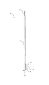
以下に図面を用いて本発明に係る土台水切りについて詳細に説明する。図1は本発明に係る土台水切りAの代表的一例を示す説明図、図2は本発明に係る土台水切りAの部材である湾曲状固定部材Bの代表的一例を示す端面図、図3は本発明に係る土台水切りAの部材である湾曲状水切り部材Cの代表的一例を示す端面図、図4は本発明に係る土台水切りAの部材である湾曲状化粧部材Dの代表的一例を示す端面図である。また、図5(a)、(b)は本発明に係る土台水切りAの代表的一例を示す説明図であり、(a)図は(b)の平面図、(b)図は正面図である。 The foundation draining according to the present invention will be described in detail below with reference to the drawings. FIG. 1 is an explanatory view showing a typical example of a foundation drainer A according to the present invention, FIG. 2 is an end view showing a representative example of a curved fixing member B that is a member of the foundation drainer A according to the present invention, and FIG. 4 is an end view showing a typical example of a curved draining member C that is a member of a foundation drainer A according to the present invention, and FIG. 4 shows a representative example of a curved decorative member D that is a member of a foundation drainer A according to the present invention. It is an end view. 5 (a) and 5 (b) are explanatory views showing a typical example of a foundation drainer A according to the present invention, (a) a plan view of (b), and (b) a front view. is there.
土台水切りAは、図1、図5(a)、(b)に示すように図2〜図4に示すような湾曲状固定部材B、湾曲状水切り部材C、湾曲状化粧部材Dの3部材よりなり、各部材を、垂直平面状に形成した第1連結部aと水平面状に形成した第2連結部bにより連結して一体に形成したものである。 As shown in FIGS. 1, 5 (a) and 5 (b), the foundation drainer A has three members: a curved fixing member B, a curved drainer member C, and a curved decorative member D as shown in FIGS. Each member is integrally formed by being connected by a first connecting part a formed in a vertical plane and a second connecting part b formed in a horizontal plane.
湾曲状固定部材Bは図2、図5(a)、(b)に示すように、垂直兼湾曲状の固定片1と、固定片1の上端を屋外側へ折り返して屈曲した舌片2と、固定片1の下端を屋内側へ折り返した第1折り返し片3と、第1折り返し片3の上端を屋内側へ折り返した第1垂下片4と、第1折り返し片3と第1垂下片4とから形成した第1嵌合溝5と、第1垂下片4の下端を屋外側へ屈曲したカシメ片6とから形成したものである。
As shown in FIGS. 2, 5A and 5B, the curved fixing member B includes a vertical and curved fixing piece 1, and a
固定片1は土台水切りAを躯体等に固定するための部分である。 The fixing piece 1 is a part for fixing the base drainer A to a frame or the like.
第1嵌合溝5は、図6に示すように後記する湾曲状水切り部材Cの上端部を嵌合し、カシメ片6を折り曲げることにより湾曲状固定部材Bと湾曲状水切り部材Cとを一体化するものである。
As shown in FIG. 6, the
湾曲状水切り部材Cは図3、図5(a)、(b)に示すように、屋外側に向かって下方に傾斜して形成した略水平兼湾曲状の水切り片7と、水切り片7の上端を上方に突出した第1挿入片8と、水切り片7の下端を屋内側に突出した第2嵌合片9と、水切り片7と第2嵌合片9とから形成した第2挿入溝10とから形成したものである。
As shown in FIGS. 3, 5 (a) and 5 (b), the curved water draining member C includes a substantially horizontal and curved water draining piece 7 that is inclined downward toward the outdoor side, A second insertion groove formed from a
第2挿入溝10は図1、図5(a)、(b)に示すように後記する湾曲状化粧部材Dの上端部を嵌合し、湾曲状水切り部材Cと湾曲状化粧部材Dとを一体化するものである。
As shown in FIGS. 1, 5 (a) and 5 (b), the
湾曲状化粧部材Dは図4、図5(a)、(b)に示すように、垂直兼湾曲状の化粧片11と、化粧片11の上端を屋内側に突出した第2折り返し片12と、第2折り返し片12の先端を屋外側へ折り返して突出した第2挿入片13と、第2折り返し片12と第2挿入片13とから形成した第2嵌合溝14と、化粧片11の下端を屋内側へ折り返した舌片15とから形成成したものである。
As shown in FIGS. 4, 5 (a), (b), the curved decorative member D includes a vertical and curved
第2挿入溝10と第2嵌合溝14共に、溝が垂直でなく水平に形成されているために、雨水等が溝内に停滞することがなく、錆等が発生せず耐候性が向上するものである。
Since both the second insertion groove 10 and the
以上説明したように、第1連結部aは湾曲状固定部材Bの固定片1の下端を屋内側へ折り返して第1折り返し片3を形成することにより、固定片1の下端が屋外側へ突出せず、美観性に優れるものである。 As described above, the first connecting portion a is configured such that the lower end of the fixed piece 1 of the curved fixing member B is folded back to the indoor side to form the first folded piece 3 so that the lower end of the fixed piece 1 protrudes to the outdoor side. Without aesthetics.
また、第2連結部bは湾曲状水切り部材Cの第2嵌合片9と第2挿入溝10、および湾曲状化粧部材Dの第2挿入片13と第2嵌合溝14が水平面状に形成されているために、雨水等が溝内に停滞することがなく、錆等が発生せず耐候性が向上するものである。
Moreover, the 2nd connection part b has the 2nd fitting piece 9 and the
土材水切りAの素材としては、金属薄板、例えば鉄、アルミニウム、銅、ステンレス、チタン、アルミ・亜鉛合金メッキ鋼板、ガルバリウム鋼板、ホーロー鋼板、クラッド鋼板、ラミネート鋼板(塩ビ鋼板等)、サンドイッチ鋼板(制振鋼板等)、塩化ビニル樹脂、ポリカーボネイト樹脂等(勿論、これらを各種色調に塗装したカラー板を含む)の一種をエンボスロール成形、あるいはプレス成形したものである。 The material for the earth drainer A is a thin metal plate such as iron, aluminum, copper, stainless steel, titanium, aluminum / zinc alloy plated steel plate, galvalume steel plate, enamel steel plate, clad steel plate, laminated steel plate (PVC steel plate, etc.), sandwich steel plate ( Damping steel plate, etc.), vinyl chloride resin, polycarbonate resin, etc. (including color plates coated with various colors, of course) are embossed roll molded or press molded.
また、土台水切りAは図5(a)、(b)に示すように、湾曲面16と平面17部分により形成し、一般部に形成する長尺状の土台水切りと連結が可能な状態に成形するものである。
Further, as shown in FIGS. 5 (a) and 5 (b), the base drainer A is formed by the
また、図では出隅部分の土台水切りAを示しているが、湾曲を逆に形成することにより、入隅部分の土台水切りAとして使用することも出来るものである。 Moreover, although the figure shows the foundation draining A in the protruding corner portion, it can also be used as the foundation draining A in the entering corner portion by forming the curve in reverse.
A 土台水切り
B 湾曲状固定部材
C 湾曲状水切り部材
D 湾曲状化粧部材
a 第1連結部
b 第2連結部
1 固定片
2 舌片
3 第1折り返し片
4 第1垂下片
5 第1嵌合溝
6 カシメ片
7 水切り片
8 第1挿入片
9 第2嵌合片
10 第2挿入溝
11 化粧片
12 第2折り返し片
13 第2挿入片
14 第2嵌合溝
15 舌片
16 湾曲面
17 平面
A Foundation drainer B Curved fixing member C Curved drainer member D Curved decorative member a First connecting portion b Second connecting portion 1
Claims (1)
Priority Applications (1)
| Application Number | Priority Date | Filing Date | Title |
|---|---|---|---|
| JP2012196896A JP6038558B2 (en) | 2012-09-07 | 2012-09-07 | Foundation drainer |
Applications Claiming Priority (1)
| Application Number | Priority Date | Filing Date | Title |
|---|---|---|---|
| JP2012196896A JP6038558B2 (en) | 2012-09-07 | 2012-09-07 | Foundation drainer |
Publications (2)
| Publication Number | Publication Date |
|---|---|
| JP2014051819A JP2014051819A (en) | 2014-03-20 |
| JP6038558B2 true JP6038558B2 (en) | 2016-12-07 |
Family
ID=50610528
Family Applications (1)
| Application Number | Title | Priority Date | Filing Date |
|---|---|---|---|
| JP2012196896A Active JP6038558B2 (en) | 2012-09-07 | 2012-09-07 | Foundation drainer |
Country Status (1)
| Country | Link |
|---|---|
| JP (1) | JP6038558B2 (en) |
Families Citing this family (1)
| Publication number | Priority date | Publication date | Assignee | Title |
|---|---|---|---|---|
| JP7052177B2 (en) * | 2018-01-23 | 2022-04-12 | ケイミュー株式会社 | Draining base for outside corner |
Family Cites Families (2)
| Publication number | Priority date | Publication date | Assignee | Title |
|---|---|---|---|---|
| JPS58111726U (en) * | 1982-01-25 | 1983-07-30 | 山本 政弘 | Copper roofing board for flat roofing |
| JPH0710181U (en) * | 1993-07-28 | 1995-02-14 | 株式会社かな和工業 | Planar building materials for curved surfaces and curved wall structures |
-
2012
- 2012-09-07 JP JP2012196896A patent/JP6038558B2/en active Active
Also Published As
| Publication number | Publication date |
|---|---|
| JP2014051819A (en) | 2014-03-20 |
Similar Documents
| Publication | Publication Date | Title |
|---|---|---|
| CN202467009U (en) | External hanging catching groove structure of plug-in type upright side hidden-interlocking roof panel | |
| CA2593808A1 (en) | Eavestrough cover | |
| JP2020204260A (en) | End structure | |
| JP6038558B2 (en) | Foundation drainer | |
| CN202611124U (en) | Roof board structure having cap end inlaid with standing edge hidden fasteners | |
| CN203782940U (en) | Reinforced decorative glass curtain wall | |
| JP6041521B2 (en) | Joint structure | |
| JP6338266B2 (en) | Keraba drainer and keraba drainer mounting structure | |
| CN210507848U (en) | Deformation joint pre-embedded assembled cover plate structure | |
| JP7052177B2 (en) | Draining base for outside corner | |
| CN202416720U (en) | Reversed-hook type vertical edge hidden-interlocking roof plate structure | |
| CN203113633U (en) | Assembling structure of profiling plate of metal roof | |
| JP2018165432A (en) | Vertical-joint joiner | |
| CN207003943U (en) | Skirt line mounting structure | |
| CN207314712U (en) | A kind of wallboard section bar | |
| CN205476340U (en) | Skirting line | |
| CN205024972U (en) | Decorate metal colored steel | |
| KR200452845Y1 (en) | Ridge ornament of metals roof | |
| CN204531262U (en) | A kind of color steel buckle | |
| CN204743269U (en) | A engagement device for filling in furniture gap | |
| JP2018155058A (en) | Joiner for longitudinal joint | |
| CN204531261U (en) | A kind of color steel buckle | |
| CN213806308U (en) | V-shaped seam metal splicing line of integrated wallboard | |
| CN216109324U (en) | Split type suspended ceiling panel structure | |
| JP2018131828A (en) | Joiner for external corner |
Legal Events
| Date | Code | Title | Description |
|---|---|---|---|
| A621 | Written request for application examination |
Free format text: JAPANESE INTERMEDIATE CODE: A621 Effective date: 20150826 |
|
| A977 | Report on retrieval |
Free format text: JAPANESE INTERMEDIATE CODE: A971007 Effective date: 20160617 |
|
| A131 | Notification of reasons for refusal |
Free format text: JAPANESE INTERMEDIATE CODE: A131 Effective date: 20160712 |
|
| A521 | Request for written amendment filed |
Free format text: JAPANESE INTERMEDIATE CODE: A523 Effective date: 20160722 |
|
| TRDD | Decision of grant or rejection written | ||
| A01 | Written decision to grant a patent or to grant a registration (utility model) |
Free format text: JAPANESE INTERMEDIATE CODE: A01 Effective date: 20161018 |
|
| A61 | First payment of annual fees (during grant procedure) |
Free format text: JAPANESE INTERMEDIATE CODE: A61 Effective date: 20161102 |
|
| R150 | Certificate of patent or registration of utility model |
Ref document number: 6038558 Country of ref document: JP Free format text: JAPANESE INTERMEDIATE CODE: R150 |
|
| R250 | Receipt of annual fees |
Free format text: JAPANESE INTERMEDIATE CODE: R250 |
|
| R250 | Receipt of annual fees |
Free format text: JAPANESE INTERMEDIATE CODE: R250 |
|
| R250 | Receipt of annual fees |
Free format text: JAPANESE INTERMEDIATE CODE: R250 |
|
| R250 | Receipt of annual fees |
Free format text: JAPANESE INTERMEDIATE CODE: R250 |
|
| R250 | Receipt of annual fees |
Free format text: JAPANESE INTERMEDIATE CODE: R250 |