JP6036131B2 - Negative operating electromagnetic brake device, control method and control device, and drive device - Google Patents
Negative operating electromagnetic brake device, control method and control device, and drive device Download PDFInfo
- Publication number
- JP6036131B2 JP6036131B2 JP2012221506A JP2012221506A JP6036131B2 JP 6036131 B2 JP6036131 B2 JP 6036131B2 JP 2012221506 A JP2012221506 A JP 2012221506A JP 2012221506 A JP2012221506 A JP 2012221506A JP 6036131 B2 JP6036131 B2 JP 6036131B2
- Authority
- JP
- Japan
- Prior art keywords
- armature
- brake
- coil
- yoke
- magnetic field
- Prior art date
- Legal status (The legal status is an assumption and is not a legal conclusion. Google has not performed a legal analysis and makes no representation as to the accuracy of the status listed.)
- Active
Links
Images


Landscapes
- Braking Arrangements (AREA)
- Dynamo-Electric Clutches, Dynamo-Electric Brakes (AREA)
Description
本発明は、例えばダイレクトドライブモータ等のモータやアクチュエータ等の種々駆動装置に搭載される負作動型電磁ブレーキ装置に関し、またその制御方法、装置及びその負作動型電磁ブレーキ装置を備えた駆動装置に関するものである。 The present invention relates to a negative operation type electromagnetic brake device mounted on various drive devices such as motors and actuators such as a direct drive motor, and also relates to a control method and apparatus thereof and a drive device including the negative operation type electromagnetic brake device. Is.
従来、モータに搭載されるブレーキとして、永久磁石を内蔵した負作動型電磁ブレーキ装置が用いられている。関連する技術として、特許文献1には、電磁ブレーキのトルク制御装置の技術が記載されている。 Conventionally, as a brake mounted on a motor, a negative operation type electromagnetic brake device incorporating a permanent magnet has been used. As a related technique, Patent Document 1 describes a technique of a torque control device for an electromagnetic brake.
図10及び図11は、負作動型電磁ブレーキ装置の動作原理を示す模式図である。図10は、負作動型電磁ブレーキ装置の解放時を示す模式図であり、図11は、負作動型電磁ブレーキ装置の作動時を示す模式図である。 10 and 11 are schematic views showing the operation principle of the negative operation type electromagnetic brake device. FIG. 10 is a schematic diagram illustrating when the negative operation type electromagnetic brake device is released, and FIG. 11 is a schematic diagram illustrating the operation of the negative operation type electromagnetic brake device.
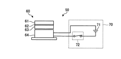
図10及び図11を参照すると、負作動型電磁ブレーキ装置50は、フランジ61と、弾性部材である板ばね62と、アーマチュア63と、マグネットヨーク64と、を含む負作動型電磁ブレーキ機構部60を備えている。板ばね62は、フランジ61に固着されており、アーマチュア63とマグネットヨーク64との間隙を広げる方向にアーマチュア63を付勢している。マグネットヨーク64は、磁性材料で作られたアーマチュア63を引き寄せる磁界を発生する永久磁石(不図示)及び永久磁石による磁界を相殺する磁界を発生させるコイル(不図示)を有する。
Referring to FIGS. 10 and 11, the negative operation type
負作動型電磁ブレーキ装置50の負作動型電磁ブレーキ機構部60を制御する制御装置70は、直流電圧発生部71と、直流電圧発生部71とマグネットヨーク64内のコイルとを接続する接続部(スイッチ)72と、を含んでいる。
The
図10を参照すると、ブレーキ解放時には、接続部72は、マグネットヨーク64の永久磁石による磁界を相殺する磁界をマグネットヨーク64のコイルに発生させるように、マグネットヨーク64のコイルと電圧発生部71とを接続する。すると、マグネットヨーク64の永久磁石がアーマチュア63を引き寄せる磁力が消失し、アーマチュア63は弾性部材である板ばね62によりフランジ61方向に付勢され、アーマチュア63とマグネットヨーク64との間に間隙が生じる。これにより、アーマチュア63とマグネットヨーク64との間の摩擦が無くなり、ブレーキが解放される。
Referring to FIG. 10, when releasing the brake, the
図11を参照すると、ブレーキ作動時には、接続部72は、マグネットヨーク64のコイルと電圧発生部71との間を開放する。すると、マグネットヨーク64のコイルが磁界を発生しないので、マグネットヨーク64の永久磁石がアーマチュア63を自身の磁力によって引き寄せ、アーマチュア63とマグネットヨーク64とが接触し、アーマチュア63とマグネットヨーク64との間に摩擦力が発生し、この摩擦力が停止トルクとしてアーマチュア63に作用し、制動力となる。また、停電などにより突然電力の供給が途絶えた場合も接続部72を開放した場合と同様に制動力が発生する。
Referring to FIG. 11, the
このように、負作動型電磁ブレーキ装置はモータ等駆動装置に搭載されるブレーキとして有効であるが、近年、回転アクチュエータの被駆動部までの長軸化に伴い、作用するモーメントが大きくなり、位置決め位置を保持する必要等のため、制動力をより高めることが好ましいことがある。 As described above, the negative operation type electromagnetic brake device is effective as a brake mounted on a drive device such as a motor. However, in recent years, as the long axis to the driven portion of the rotary actuator becomes longer, the acting moment increases and the positioning is performed. It may be preferable to increase the braking force because of the need to maintain the position.
本発明は、上記に鑑みてなされたものであって、負作動型電磁ブレーキ装置の制動力をより高めることを目的とする。 This invention is made | formed in view of the above, Comprising: It aims at raising the braking force of a negative action type electromagnetic brake device more.
上述した課題を解決し、目的を達成するために、本発明は、アーマチュアと、前記アーマチュアを引き寄せる磁界を発生する第1の永久磁石及び前記アーマチュアを引き寄せる磁界を変化させるコイルを有するマグネットヨークと、前記アーマチュアと前記マグネットヨークとの間隙を広げる方向に前記アーマチュアを付勢する弾性部材と、ブレーキの作動を制御する制御装置と、を含む負作動型電磁ブレーキ装置であって、前記アーマチュアには、第2の永久磁石を備えていることを特徴とする負作動型電磁ブレーキ装置を提供する。
また、本発明は、前記第1の永久磁石と前記第2の永久磁石とは、互いに引き寄せ合う向きに設置されていることを特徴とする負作動型電磁ブレーキ装置を提供する。
また、本発明は、前記第2の永久磁石は、第1のアーマチュアヨークと第2のアーマチュアヨークとに挟まれており、固着されていることを特徴とする負作動型電磁ブレーキ装置を提供する。
また、本発明は、前記第1のアーマチュアヨークは、円環状の板形状となっており、前記第2のアーマチュアヨークは、外周部と内周部とで厚さの異なる円環状の板形状となっていることを特徴とする負作動型電磁ブレーキ装置を提供する。
また、本発明は、前記制御装置には、直流電圧を発生する直流電圧発生部と、ブレーキ解放時には、前記マグネットヨークの前記アーマチュアを引き寄せる磁界を弱めるように前記コイルと前記直流電圧発生部とを接続し、ブレーキ作動時には、前記マグネットヨークの前記アーマチュアを引き寄せる磁界を強めるように前記コイルと前記直流電圧発生部とを接続する接続部と、を備えることを特徴とする負作動型電磁ブレーキ装置を提供する。
In order to solve the above-described problems and achieve the object, the present invention includes an armature, a first permanent magnet that generates a magnetic field that attracts the armature, and a magnet yoke that includes a coil that changes the magnetic field that attracts the armature. A negative operation type electromagnetic brake device including an elastic member that urges the armature in a direction to widen a gap between the armature and the magnet yoke, and a control device that controls the operation of a brake. A negative operation type electromagnetic brake device comprising a second permanent magnet is provided.
In addition, the present invention provides a negatively operated electromagnetic brake device, wherein the first permanent magnet and the second permanent magnet are installed in a direction that attracts each other.
The present invention also provides a negatively operated electromagnetic brake device characterized in that the second permanent magnet is sandwiched and fixed between a first armature yoke and a second armature yoke. .
According to the present invention, the first armature yoke has an annular plate shape, and the second armature yoke has an annular plate shape having different thicknesses at an outer peripheral portion and an inner peripheral portion. A negatively operated electromagnetic brake device is provided.
Further, according to the present invention, the control device includes a DC voltage generating unit that generates a DC voltage, and the coil and the DC voltage generating unit so as to weaken a magnetic field that attracts the armature of the magnet yoke when the brake is released. A negatively operated electromagnetic brake device comprising: a connecting portion for connecting the coil and the DC voltage generating portion so as to strengthen the magnetic field that attracts the armature of the magnet yoke when the brake is operated. provide.
このように、負作動型電磁ブレーキ装置の作動時に、マグネットヨークのアーマチュアを引き寄せる磁界を強めるようにコイルに直流電圧を印加することで、マグネットヨークのアーマチュアを引き寄せる磁界を強めることができる。これにより、負作動型電磁ブレーキ装置の制動力をより高めることができる。 As described above, when the negative operation type electromagnetic brake device is operated, the magnetic field attracting the armature of the magnet yoke can be strengthened by applying the DC voltage to the coil so as to strengthen the magnetic field attracting the armature of the magnet yoke. Thereby, the braking force of a negative action type electromagnetic brake device can be raised more.
また、本発明は、ブレーキ作動時には、ブレーキ解放時とは逆方向に、前記コイルへ直流電圧を印加することを特徴とする負作動型電磁ブレーキ装置を提供する。 In addition, the present invention provides a negatively operated electromagnetic brake device that applies a DC voltage to the coil in the reverse direction to the brake release when the brake is operated.
また、本発明は、前記直流電圧発生部が、一定の直流電圧を発生する単一のものであることを特徴とする負作動型電磁ブレーキ装置を提供する。これにより、単一の直流電圧発生部で負作動型電磁ブレーキ装置の作動及び解放を行うことができるので、制御装置の簡略化、低コスト化を図ることができる。
また、本発明は、前記直流電圧発生部が、複数からなり、ブレーキ解放用のものと、ブレーキ作動用のものと、を独立して有することを特徴とする負作動型電磁ブレーキ装置を提供する。
また、本発明は、前記直流電圧発生部について、ブレーキ作動用のものがブレーキ解放用のものより、発生する電圧が大きいことを特徴とする負作動型電磁ブレーキ装置を提供する。
また、本発明は、前記直流電圧発生部について、ブレーキ作動用のものがブレーキ解放用のものより、発生する電圧が小さいことを特徴とする負作動型電磁ブレーキ装置を提供する。
また、本発明は、前記直流電圧発生部について、ブレーキ作動用のものに可変抵抗器を有し、発生する電圧を変化させることができ、ブレーキトルクの制御を可能としていることを特徴とする負作動型電磁ブレーキ装置を提供する。
また、本発明は、アーマチュアと、前記アーマチュアを引き寄せる磁界を発生する第1の永久磁石及び前記アーマチュアを引き寄せる磁界を変化させるコイルを有するマグネットヨークと、前記アーマチュアと前記マグネットヨークとの間隙を広げる方向に前記アーマチュアを付勢する弾性部材と、ブレーキの作動を制御する制御装置と、前記アーマチュアに備えられている第2の永久磁石と、を含む負作動型電磁ブレーキ装置を制御する方法であって、ブレーキ解放時には、前記マグネットヨークの前記アーマチュアを引き寄せる磁界を弱めるように前記コイルに直流電圧を印加し、ブレーキ作動時には、前記マグネットヨークの前記アーマチュアを引き寄せる磁界を強めるように前記コイルに直流電圧を印加することを特徴とする負作動型電磁ブレーキ装置の制御方法を提供する。
また、本発明は、アーマチュアと、前記アーマチュアを引き寄せる磁界を発生する第1の永久磁石及び前記アーマチュアを引き寄せる磁界を変化させるコイルを有するマグネットヨークと、前記アーマチュアと前記マグネットヨークとの間隙を広げる方向に前記アーマチュアを付勢する弾性部材と、前記アーマチュアに備えられている第2の永久磁石と、を含む負作動型電磁ブレーキ装置を制御する制御装置であって、前記制御装置には、直流電圧を発生する直流電圧発生部と、ブレーキ解放時には、前記マグネットヨークの前記アーマチュアを引き寄せる磁界を弱めるように前記コイルと前記直流電圧発生部とを接続し、ブレーキ作動時には、前記マグネットヨークの前記アーマチュアを引き寄せる磁界を強めるように前記コイルと前記直流電圧発生部とを接続する接続部と、を備えることを特徴とする負作動型電磁ブレーキ装置の制御装置を提供する。
また、本発明は、上記の負作動型電磁ブレーキ装置を備えたことを特徴とする駆動装置を提供する。
In addition, the present invention provides a negative operation type electromagnetic brake device in which the DC voltage generator is a single unit that generates a constant DC voltage. Thereby, since the negative operation type electromagnetic brake device can be operated and released by a single DC voltage generator, the control device can be simplified and the cost can be reduced.
The present invention also provides a negative operation type electromagnetic brake device comprising a plurality of the DC voltage generators, each having a brake release member and a brake operation member independently. .
The present invention also provides a negatively operated electromagnetic brake device characterized in that the DC voltage generating unit generates a larger voltage for brake operation than for brake release.
The present invention also provides a negative operation type electromagnetic brake device in which the DC voltage generating unit generates a smaller voltage for brake operation than for brake release.
Further, the present invention provides a negative resistor characterized in that the DC voltage generating part has a variable resistor for the brake operation, can change the generated voltage, and can control the brake torque. An actuating electromagnetic brake device is provided.
The present invention also provides an armature, a first permanent magnet that generates a magnetic field that attracts the armature, a magnet yoke having a coil that changes the magnetic field that attracts the armature, and a direction in which a gap between the armature and the magnet yoke is widened. And a control device for controlling the operation of the brake, and a second permanent magnet provided in the armature. When the brake is released, a DC voltage is applied to the coil so as to weaken the magnetic field attracting the armature of the magnet yoke, and when the brake is operated, a DC voltage is applied to the coil so as to strengthen the magnetic field attracting the armature of the magnet yoke. Negative action characterized by applying A control method of an electromagnetic brake system.
The present invention also provides an armature, a first permanent magnet that generates a magnetic field that attracts the armature, a magnet yoke having a coil that changes the magnetic field that attracts the armature, and a direction in which a gap between the armature and the magnet yoke is widened. A control device for controlling a negatively operated electromagnetic brake device including an elastic member for urging the armature and a second permanent magnet provided in the armature, the control device including a DC voltage A DC voltage generating unit that generates the magnetic yoke, and when the brake is released, the coil and the DC voltage generating unit are connected so as to weaken a magnetic field that attracts the armature of the magnet yoke, and when the brake is operated, the armature of the magnet yoke is The coil and the direct so as to strengthen the attracting magnetic field. To provide a control apparatus of a negative working type electromagnetic brake device, characterized in that it comprises a connecting portion for connecting the voltage generating unit.
Moreover, this invention provides the drive device characterized by including said negative action type electromagnetic brake device.
本発明は、負作動型電磁ブレーキ装置の制動力をより高めることができる。 The present invention can further increase the braking force of the negative operation type electromagnetic brake device.
以下、本発明につき図面を参照しつつ詳細に説明する。なお、この発明を実施するための形態(以下、実施形態という)により本発明が限定されるものではない。また、以下の説明における構成要素には、当業者が容易に想定できるもの、実質的に同一のもの、いわゆる均等の範囲のものが含まれる。 Hereinafter, the present invention will be described in detail with reference to the drawings. The present invention is not limited by the mode for carrying out the invention (hereinafter referred to as an embodiment). In addition, constituent elements in the following description include those that can be easily assumed by those skilled in the art, those that are substantially the same, and those in a so-called equivalent range.
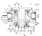
図1は、負作動型電磁ブレーキ装置を有するダイレクトドライブモータの回転軸を含む平面での断面図である。本実施形態においては、負作動型電磁ブレーキ装置及び本実施形態に係る制御方法をダイレクトドライブモータ1に適用した例を示すが、負作動型電磁ブレーキ装置及び本実施形態に係る制御方法の適用対象は、ダイレクトドライブモータ1に限定されるものではない。直動アクチュエータ等を含む駆動装置全般に適用できる。 FIG. 1 is a cross-sectional view in a plane including a rotation shaft of a direct drive motor having a negative operation type electromagnetic brake device. In the present embodiment, an example in which the negative operation type electromagnetic brake device and the control method according to the present embodiment are applied to the direct drive motor 1 is shown, but the negative operation type electromagnetic brake device and the control method according to the present embodiment are applicable. Is not limited to the direct drive motor 1. It can be applied to all drive devices including linear actuators.
ダイレクトドライブモータ1は、モータベース20を有する。モータベース20は、ダイレクトドライブモータ1の回転中心軸Zrと同軸の円筒状部20Bを有する。また、モータベース20は、円筒状部20Bの軸方向の第1の方向の端部から外方向に拡がる円環状部20Rを有する。第1の方向とは、回転中心軸Zrと平行な方向かつ後述する回転部10側に向く(図1において下向きの)方向である。
The direct drive motor 1 has a
モータベース20の円筒状部20Bと円環状部20Rとの境界部分の第1の方向側には、マグネットヨーク21が、ダイレクトドライブモータ1の回転中心軸Zrと同軸にボルトで緊締し固着されている。マグネットヨーク21は、軟磁性体のヨーク21A、21B、21Cを有する。ヨーク21Aは、ダイレクトドライブモータ1の回転中心軸Zrと同軸の円環状の形状を有する。また、マグネットヨーク21は、ヨーク21Aの内周部から第1の方向に沿って延在する円筒状のヨーク21Bを有する。ヨーク21Aの外周部の第1の方向側の面には、アーマチュア10cを引き寄せる磁界を発生する、硬磁性体の第1の永久磁石21Dが固着されている。ヨーク21Cは、第1の永久磁石21Dの第1の方向側の面に固着された円環状部21Caと、円環状部21Caの第1の方向側の面の外周部から第1の方向に延在する円筒状部21Cbと、を有する。ヨーク21Bの外周とヨーク21Cの円筒状部21Cbの内周との間には、ダイレクトドライブモータ1の回転中心軸Zrと同軸に、第1の永久磁石21Dによる磁界を変化させる磁界を発生させるコイル21Eが巻回されている。マグネットヨーク21の外周面には、コイル21Eに電圧を印加するためのリード線24が設けられている。モータベース20の円環状部20Rの第1の方向と反対の第2の方向側の面の外周部には、モータコア26A及び巻線26Bが配置されている。これらの部材がステータ2を構成する。
On the first direction side of the boundary portion between the
マグネットヨーク21及び後述する回転部10が、負作動型電磁ブレーキ装置のブレーキ機構部25を構成する。
The
ダイレクトドライブモータ1は、負作動型電磁ブレーキ装置のブレーキ機構部25の制動力をロータ3のモータ出力軸13に伝達するブレーキ連結軸12を有する。ブレーキ連結軸12は、ダイレクトドライブモータ1の回転中心軸Zrと同軸の円環状部12Rと、円環状部12Rの内周側を含む中央部から第1の方向に向かって延在する円筒状部12Bと、を有する。ブレーキ連結軸12の円筒状部12Bは、第2の方向側から第1の方向側に向かって、モータベース20及びマグネットヨーク21を貫通している。
The direct drive motor 1 has a
ブレーキ連結軸12の円筒状部12Bの第1の方向側の端部には、ブレーキ機構部25の回転部10が取付けられている。回転部10は、フランジ10aと、弾性部材である板ばね10bと、アーマチュア10cと、を有する。フランジ10aは、円盤状の形状を有しており、ブレーキ連結軸12の円筒状部12Bの第1の方向側の端部にボルトで緊締し固着されている。板ばね10b及びアーマチュア10cは、円環状の形状を有している。アーマチュア10cは、板ばね10bを挟んで、フランジ10aの第2の方向側の面に固着されている。板ばね10bは、アーマチュア10cを第1の方向(フランジ10a側)に引っ張るように付勢している。板ばね10bはフランジ10aとアーマチュア10cとの両方に固定されている。板ばね10bは、面内剛性が低いため、ブレーキ作動時にはアーマチュア10cに作用する磁力によって引っ張られ軸方向に変形してたわむが、周方向への剛性は非常に高いため、周方向への変形は小さい。
このような構造により、コイル21Eに印加する電圧でブレーキの解放や作動を制御する。ブレーキ解放時には、第1の永久磁石21Dの磁力を弱める方向に磁界が発生するようコイル21Eに電圧が印加される。これにより、アーマチュア10cは、板ばね10bにより第1の方向(フランジ10a側)に引っ張られ、マグネットヨーク21とアーマチュア10cとの間に間隙ができブレーキが解放される。一方、ブレーキが作動すると、ブレーキ機構部25は、ロータ3を制動して所定の位置に固定することができる。マグネットヨーク21のコイル21Eに電圧を印加しないと、マグネットヨーク21のコイル21Eが磁界を発生しないので、マグネットヨーク21の第1の永久磁石21Dがアーマチュア10cを自身の磁力によって引き寄せ、アーマチュア10cとマグネットヨーク21とが接触する。その結果、アーマチュア10cとマグネットヨーク21との間に摩擦力が発生し、この摩擦力が停止トルクとしてアーマチュア10cに作用し、ダイレクトドライブモータ1のロータ3の制動力となる。本発明では、更に制動力を高めるために、第1の永久磁石21Dの磁力に加えて、コイル21Eの磁力も付与できるような電圧を印加する。これについては、実施例を用いて後述する。
The rotating
With such a structure, the brake release and operation are controlled by the voltage applied to the
また、本発明では、更に制動力を高めるために、アーマチュア10cに第2の永久磁石10eを備えている。第1の永久磁石21Dと第2の永久磁石10eとは、互いに引き寄せ合う向きに設置されている。第2の永久磁石10eは、第1のアーマチュアヨーク10dと第2のアーマチュアヨーク10fとに挟まれている。第2の永久磁石10eは、両アーマチュアヨーク10d,10fに固着されている。第1のアーマチュアヨーク10dは、円環状の板形状となっており、第2のアーマチュアヨーク10fは、外周部と内周部とで厚さの異なる円環状の板形状となっている。図1に示す本実施形態では、第2のアーマチュアヨーク10fは、内周部が外周部より厚くなっている。この内周部と外周部との厚さの差は、永久磁石10eの厚さより大きくなっている。
このように、静止体であるマグネットヨーク21に第1の永久磁石21Dを、回転体であるアーマチュア10cに第2の永久磁石10eを、磁気回路上、非通電状態で互いに引き寄せ合う極性で配置することにより、磁力を上げることができブレーキ力を上げることができる。高磁力の永久磁石はレアアースを含有しており、昨今、価格が高騰している。数年で10倍になったネオジム系磁石を代表に永久磁石及び、ジスプロシウム等永久磁石への添加物の価格高騰は非常に著しい。コストを軽減するためには、比較的表面磁束の低い、フェライト系磁石のような、廉価な永久磁石を使わざるを得なくなってきている。しかし、このような廉価な永久磁石を使用したものでは、従来のブレーキ構造では、本来必要としているブレ−キトルクが得られない。本発明の実施形態では、廉価な永久磁石を使用しても必要なブレーキトルクを得うる構成となっている。また、フェライト系磁石を用いることにより、高温での使用も可能な電磁ブレーキとなっている。
ブレーキ連結軸12の円環状部12Rの第1の方向側の面の外周部には、ダイレクトドライブモータ1の回転中心軸Zrと同軸の円筒状のモータ出力軸13がボルトで緊締され固着されている。モータ出力軸13の第1の方向側の端部には、ダイレクトドライブモータ1の回転中心軸Zrと同軸のロータフランジ14が固着されている。ロータフランジ14の外周面には、ステータ2側のモータコア26A及び巻線26Bと対向するように、永久磁石15が配置されている。これらの部材がロータ3を構成する。
In the present invention, in order to further increase the braking force, the
In this way, the first
A cylindrical
ロータフランジ14の内周面と、モータベース20の円筒状部20Bの外周面と、の間には、クロスローラ軸受27が配置されている。クロスローラ軸受27は、アキシアル荷重とモーメント荷重を受けることができる。
A
(実施例1)
図2及び図3は、本発明の第1実施例に係る負作動型電磁ブレーキ装置の制御装置とブレーキ機構部とを接続した様子を示す模式図である。図2は、負作動型電磁ブレーキ装置の解放時を示す模式図であり、図3は、負作動型電磁ブレーキ装置の作動時を示す模式図である。
Example 1
2 and 3 are schematic views showing a state in which the control device of the negative operation type electromagnetic brake device according to the first embodiment of the present invention and the brake mechanism unit are connected. FIG. 2 is a schematic diagram illustrating when the negative operation type electromagnetic brake device is released, and FIG. 3 is a schematic diagram illustrating the operation of the negative operation type electromagnetic brake device.
負作動型電磁ブレーキ装置30を制御する負作動型電磁ブレーキ装置の制御装置(以下、必要に応じて制御装置という)40は、リード線24(図1参照)を介してブレーキ機構部25と接続されている。制御装置40は、所定の直流電圧(例えば、24V)を発生する直流電圧発生部41と、直流電圧発生部41とマグネットヨーク21内のコイル21E(図1参照)とを接続する接続部(スイッチ)42と、を含んでいる。
A control device (hereinafter referred to as a control device if necessary) 40 for controlling the negative operation type
図2を参照すると、ブレーキ解放時には、接続部42は、マグネットヨーク21内の第1の永久磁石21D(図1参照)によるアーマチュア10cを引き寄せる磁界を弱めるようにコイル21Eに直流電圧を印加すべく、コイル21Eと直流電圧発生部41とを接続する。すると、コイル21Eが発生する磁界により、ヨーク21A、21B、21C(図1参照)が磁化する。このときにヨーク21A、21B、21Cに発生する磁束の方向に、コイル21Eに流れる電流の向きによって変化する。ヨーク21A、21B、21Cの磁束の方向が第1の永久磁石21Dの磁束の方向と反対である場合、マグネットヨーク21中に存在する磁束の量が低減する。その結果、マグネットヨーク21がアーマチュア10cを引き寄せる磁界が弱められ(相殺されることが好ましい)、アーマチュア10cは弾性部材である板ばね10bによりフランジ10a方向に付勢され、アーマチュア10cとマグネットヨーク21との間に間隙が生じる。これにより、アーマチュア10cとマグネットヨーク21との間の摩擦が無くなり、ブレーキが解放される。
Referring to FIG. 2, when the brake is released, the connecting
図3を参照すると、ブレーキ作動時には、接続部42は、ブレーキ解放時とは逆方向に、直流電圧がマグネットヨーク21内のコイル21Eに印加されるように、コイル21Eと直流電圧発生部41とを接続する。つまり、接続部42は、マグネットヨーク21のアーマチュア10cを引き寄せる磁界を強めるようにコイル21Eに直流電圧を印加する。すると、コイル21Eが発生する磁界と第1の永久磁石21Dによる磁界とが重ね合わされて、マグネットヨーク21がアーマチュア10cを引き寄せる磁界が強められ、マグネットヨーク21がアーマチュア10cを強い磁力によって引き寄せ、アーマチュア10cとマグネットヨーク21とが接触し、アーマチュア10cとマグネットヨーク21との間に摩擦力が発生し、この摩擦力が停止トルクとしてアーマチュア10cに作用し、ダイレクトドライブモータ1のロータ3の制動力となる。
Referring to FIG. 3, when the brake is operated, the connecting
このように、ブレーキ作動時に、解放時と逆の電圧をマグネットヨーク21のコイル21Eに印加することで、マグネットヨーク21は、マグネットヨーク21の第1の永久磁石21Dによる磁界とコイル21Eの磁界とを加えた磁界を発生させることができる。その結果、負作動型電磁ブレーキ装置30は、アーマチュア10cとマグネットヨーク21との間の制動トルクを従来よりも強くすることができる。これにより、負作動型電磁ブレーキ装置30は、ダイレクトドライブモータ1のロータ3の制動力をより高めることができる。これは、近年、回転アクチュエータにおいて被駆動部までの長軸化等に伴い、作用するモーメントが大きくなってきており、位置決め位置での確実な停止や保持をする上で有用な効果がある。
In this manner, when the brake is operated, a voltage opposite to that at the time of release is applied to the
なお、コイル21Eによる磁力と第1の永久磁石21Dの磁力とで、マグネットヨーク21のヨーク21A、21B、21Cが磁気飽和した後は、コイル21Eによる磁界をそれ以上強くしても負作動型電磁ブレーキ装置30が発生する磁界は、磁気飽和したとき以上には大きくならない。そのため、コイル21Eに印加する電圧は、コイル21Eによる磁界と第1の永久磁石21Dの磁界とで、ヨーク21A、21B、21Cが磁気飽和するまでの電圧とすることが好ましい。
After the
また、本実施例においては、ブレーキ作動時に、解放時と逆方向かつ同じ大きさの直流電圧をマグネットヨーク21のコイル21Eに印加することとしているが、本発明はこれに限定されない。本発明においては、アーマチュア10cを引き寄せる磁界を強める電圧を、マグネットヨーク21のコイル21Eに印加すればよい。つまり、ブレーキ作動時の電圧の絶対値が、解放時の電圧の絶対値より大きくてもよいし、小さくてもよい。マグネットヨーク21のヨーク21A、21B、21Cが磁気飽和しない範囲で、ブレーキ作動時の電圧の絶対値を大きくすると、制動力が高くなり好適である。この例として、第2実施例を上げて後述する。
Further, in this embodiment, when the brake is operated, a DC voltage having the same direction and the same magnitude as that in the release is applied to the
また、本実施例のように、ブレーキ作動時に、解放時と逆方向に同じ大きさの直流電圧をマグネットヨーク21のコイル21Eに印加することとすれば、単一の直流電圧発生部41でブレーキの作動及び解放を行うことができるので、制御装置40の簡略化、低コスト化を図ることができる。
Further, as in the present embodiment, when a DC voltage having the same magnitude is applied to the
(実施例2)
図4及び図5は、本発明の第2実施例に係る負作動型電磁ブレーキ装置の制御装置とブレーキ機構部とを接続した様子を示す模式図である。図4は、負作動型電磁ブレーキ装置の解放時を示す模式図であり、図5は、負作動型電磁ブレーキ装置の作動時を示す模式図である。本実施例においては、前述の第1実施例と同様の部位については、共通の符号を用い説明を省略する。
(Example 2)
4 and 5 are schematic views showing a state in which the control device of the negative operation type electromagnetic brake device according to the second embodiment of the present invention and the brake mechanism unit are connected. FIG. 4 is a schematic diagram showing when the negatively operated electromagnetic brake device is released, and FIG. 5 is a schematic diagram showing when the negatively operated electromagnetic brake device is operated. In the present embodiment, the same parts as those in the first embodiment described above are denoted by common reference numerals and the description thereof is omitted.
本実施例が第1実施例と異なる点は、ブレーキの解放用直流電圧発生部41aと作動用直流電圧発生部41bとを独立させ、互いの電圧の絶対値を変えていることである。互いの電圧の方向は、第1実施例と同様に相反するようになっている。本実施例においては、作動用直流電圧発生部41bの電圧の大きさは、解放用直流電圧発生部41aの電圧の大きさより大きい。これにより、ブレーキによる制動力を向上させブレーキの作動時間を短縮することができる。また、ブレーキ作動時の剛性を高めることができる。
This embodiment differs from the first embodiment in that the brake release
(実施例3)
図6及び図7は、本発明の第3実施例に係る負作動型電磁ブレーキ装置の制御装置とブレーキ機構部とを接続した様子を示す模式図である。図6は、負作動型電磁ブレーキ装置の解放時を示す模式図であり、図7は、負作動型電磁ブレーキ装置の作動時を示す模式図である。本実施例においては、前述の第1実施例と同様の部位については、共通の符号を用い説明を省略する。
Example 3
6 and 7 are schematic views showing a state where the control device of the negative operation type electromagnetic brake device according to the third embodiment of the present invention and the brake mechanism unit are connected. FIG. 6 is a schematic diagram illustrating when the negative operation type electromagnetic brake device is released, and FIG. 7 is a schematic diagram illustrating the operation of the negative operation type electromagnetic brake device. In the present embodiment, the same parts as those in the first embodiment described above are denoted by common reference numerals and the description thereof is omitted.
本実施例が第1実施例と異なる点は、ブレーキの解放用直流電圧発生部41aと作動用直流電圧発生部41bとを独立させ、互いの電圧の絶対値を変えていることである。互いの電圧の方向は、第1実施例と同様に相反するようになっている。本実施例においては、作動用直流電圧発生部41bの電圧の大きさは、解放用直流電圧発生部41aの電圧の大きさより小さい。これにより、第1の永久磁石21D(図1参照)の磁力を強める磁力は、第1実施例の場合より少なくはなるが、ブレーキの解放にかかる時間を短縮することができる。
This embodiment differs from the first embodiment in that the brake release
(実施例4)
図8及び図9は、本発明の第4実施例に係る負作動型電磁ブレーキ装置の制御装置とブレーキ機構部とを接続した様子を示す模式図である。図8は、負作動型電磁ブレーキ装置の解放時を示す模式図であり、図9は、負作動型電磁ブレーキ装置の作動時を示す模式図である。本実施例においては、前述の第1実施例と同様の部位については、共通の符号を用い説明を省略する。
Example 4
FIGS. 8 and 9 are schematic views showing a state in which the control device of the negatively operated electromagnetic brake device and the brake mechanism unit according to the fourth embodiment of the present invention are connected. FIG. 8 is a schematic diagram illustrating when the negative operation type electromagnetic brake device is released, and FIG. 9 is a schematic diagram illustrating the operation of the negative operation type electromagnetic brake device. In the present embodiment, the same parts as those in the first embodiment described above are denoted by common reference numerals and the description thereof is omitted.
本実施例が第1実施例と異なる点は、ブレーキの解放用直流電圧発生部41aと作動用直流電圧発生部41bとを独立させ、互いの電圧の絶対値を可変にしていることである。互いの電圧の方向は、第1実施例と同様に相反するようになっている。本実施例においては、作動用直流電圧発生部41bの電圧の大きさは、可変抵抗器43により可変となっている。これにより、ブレーキによる制動力を変化させることができる。例えば、ブレーキの制動力を高めたいときには可変抵抗器43により電圧を高くし、ブレーキの解放時間を短縮させたいときには、電圧を低くすることで対応できる。また、ある一定の外部からの印加トルクがかかった場合に内部機器を破損させないために、可変抵抗器43により、ブレーキが一定のトルクですべり出すように調整することも可能である。
This embodiment differs from the first embodiment in that the brake release
1 ダイレクトドライブモータ
2 ステータ
3 ロータ
10 回転部
10a、61 フランジ
10b、62 板ばね(弾性部材)
10c、63 アーマチュア
10d 第1のアーマチュアヨーク
10e 第2の永久磁石
10f 第2のアーマチュアヨーク
12 ブレーキ連結軸
13 モータ出力軸
14 ロータフランジ
15 永久磁石
20 モータベース
21、64 マグネットヨーク
21A、21B、21C ヨーク
21D 第1の永久磁石
21E コイル
24 リード線
25、60 ブレーキ機構部
26A モータコア
26B 巻線
27 クロスローラ軸受
30、50 負作動型電磁ブレーキ装置
40、70 制御装置(負作動型電磁ブレーキ装置の制御装置)
41、71 直流電圧発生部
41a 解放用直流電圧発生部
41b 作動用直流電圧発生部
42、72 接続部(スイッチ)
43 可変抵抗器
DESCRIPTION OF SYMBOLS 1 Direct drive motor 2
10c, 63
41, 71
43 Variable resistor
Claims (7)
前記制御装置は、
ブレーキ解放用の第1の直流電圧発生部と、
ブレーキ作動用の第2の直流電圧発生部と、
前記第2の直流電圧発生部に直列に接続された可変抵抗器と、
ブレーキ解放時には、前記マグネットヨークの前記アーマチュアを引き寄せる磁界を弱めるように前記コイルと前記第1の直流電圧発生部とを直列接続し、ブレーキ作動時には、前記マグネットヨークの前記アーマチュアを引き寄せる磁界を強めるように前記コイルと前記第2の直流電圧発生部と前記可変抵抗器とを直列接続する接続部と、
を備え、
ブレーキ解放時の前記コイルへの印加電圧を保ったまま、ブレーキ作動時の前記コイルへの印加電圧を可変にすることで、ブレーキトルクの調整を可能とする制御を行うことを特徴とする負作動型電磁ブレーキ装置。 An armature, a first permanent magnet for generating a magnetic field for attracting the armature, a magnet yoke having a coil for changing the magnetic field for attracting the armature, and urging the armature in a direction to widen a gap between the armature and the magnet yoke A negative operation type electromagnetic brake device including a second permanent magnet in the armature, and an elastic member including a control device for controlling the operation of the brake .
The controller is
A first DC voltage generator for releasing the brake;
A second DC voltage generator for operating the brake;
A variable resistor connected in series to the second DC voltage generator;
When releasing the brake, the coil and the first DC voltage generator are connected in series so as to weaken the magnetic field attracting the armature of the magnet yoke, and when braking, the magnetic field attracting the armature of the magnet yoke is strengthened. A connecting portion for connecting the coil, the second DC voltage generating portion, and the variable resistor in series;
With
Negative operation characterized in that control is performed to enable adjustment of brake torque by making variable the voltage applied to the coil during brake operation while maintaining the voltage applied to the coil when the brake is released. Type electromagnetic brake device.
前記制御装置は、
ブレーキ解放用の第1の直流電圧発生部と、
ブレーキ作動用の第2の直流電圧発生部と、
前記第2の直流電圧発生部に直列に接続された可変抵抗器と、
を備え、
ブレーキ解放時には、前記マグネットヨークの前記アーマチュアを引き寄せる磁界を弱めるように前記コイルと前記第1の直流電圧発生部を直列接続し、
ブレーキ作動時には、前記マグネットヨークの前記アーマチュアを引き寄せる磁界を強めるように前記コイルと前記第2の直流電圧発生部と前記可変抵抗器とを直列接続することにより、
ブレーキ解放時の前記コイルへの印加電圧を保ったまま、ブレーキ作動時の前記コイルへの印加電圧を可変にすることで、ブレーキトルクの調整を可能とする制御を行うことを特徴とする負作動型電磁ブレーキ装置の制御方法。 An armature, a first permanent magnet for generating a magnetic field for attracting the armature, a magnet yoke having a coil for changing the magnetic field for attracting the armature, and urging the armature in a direction to widen a gap between the armature and the magnet yoke A method for controlling a negatively actuated electromagnetic brake device, comprising: an elastic member for controlling the operation of a brake; and a second permanent magnet provided in the armature,
The controller is
A first DC voltage generator for releasing the brake;
A second DC voltage generator for operating the brake;
A variable resistor connected in series to the second DC voltage generator;
With
When releasing the brake, the coil and the first DC voltage generator are connected in series so as to weaken the magnetic field attracting the armature of the magnet yoke,
When the brake is operated, the coil , the second DC voltage generator, and the variable resistor are connected in series so as to strengthen the magnetic field that attracts the armature of the magnet yoke .
Negative operation characterized in that control is performed to enable adjustment of brake torque by making variable the voltage applied to the coil during brake operation while maintaining the voltage applied to the coil when the brake is released. Type electromagnetic brake device control method.
ブレーキ解放用の第1の直流電圧発生部と、
ブレーキ作動用の第2の直流電圧発生部と、
前記第2の直流電圧発生部に直列に接続された可変抵抗器と、
ブレーキ解放時には、前記マグネットヨークの前記アーマチュアを引き寄せる磁界を弱めるように前記コイルと前記第1の直流電圧発生部とを直列接続し、ブレーキ作動時には、前記マグネットヨークの前記アーマチュアを引き寄せる磁界を強めるように前記コイルと前記第2の直流電圧発生部と前記可変抵抗器とを直列接続する接続部と、
を備え、
ブレーキ解放時の前記コイルへの印加電圧を保ったまま、ブレーキ作動時の前記コイルへの印加電圧を可変にすることで、ブレーキトルクの調整を可能とする制御を行うことを特徴とする負作動型電磁ブレーキ装置の制御装置。 An armature, a first permanent magnet for generating a magnetic field for attracting the armature, a magnet yoke having a coil for changing the magnetic field for attracting the armature, and urging the armature in a direction to widen a gap between the armature and the magnet yoke A control device for controlling a negatively actuated electromagnetic brake device, comprising: an elastic member to be operated; and a second permanent magnet provided in the armature,
A first DC voltage generator for releasing the brake;
A second DC voltage generator for operating the brake;
A variable resistor connected in series to the second DC voltage generator;
When releasing the brake, the coil and the first DC voltage generator are connected in series so as to weaken the magnetic field attracting the armature of the magnet yoke, and when braking, the magnetic field attracting the armature of the magnet yoke is strengthened. A connecting portion for connecting the coil, the second DC voltage generating portion, and the variable resistor in series;
Equipped with a,
Negative operation characterized in that control is performed to enable adjustment of brake torque by making variable the voltage applied to the coil during brake operation while maintaining the voltage applied to the coil when the brake is released. Type electromagnetic brake device control device.
Priority Applications (1)
| Application Number | Priority Date | Filing Date | Title |
|---|---|---|---|
| JP2012221506A JP6036131B2 (en) | 2012-10-03 | 2012-10-03 | Negative operating electromagnetic brake device, control method and control device, and drive device |
Applications Claiming Priority (1)
| Application Number | Priority Date | Filing Date | Title |
|---|---|---|---|
| JP2012221506A JP6036131B2 (en) | 2012-10-03 | 2012-10-03 | Negative operating electromagnetic brake device, control method and control device, and drive device |
Publications (2)
| Publication Number | Publication Date |
|---|---|
| JP2014075894A JP2014075894A (en) | 2014-04-24 |
| JP6036131B2 true JP6036131B2 (en) | 2016-11-30 |
Family
ID=50749678
Family Applications (1)
| Application Number | Title | Priority Date | Filing Date |
|---|---|---|---|
| JP2012221506A Active JP6036131B2 (en) | 2012-10-03 | 2012-10-03 | Negative operating electromagnetic brake device, control method and control device, and drive device |
Country Status (1)
| Country | Link |
|---|---|
| JP (1) | JP6036131B2 (en) |
Families Citing this family (1)
| Publication number | Priority date | Publication date | Assignee | Title |
|---|---|---|---|---|
| JP7501332B2 (en) | 2020-12-07 | 2024-06-18 | 日本精工株式会社 | Rotary Actuator |
Family Cites Families (5)
| Publication number | Priority date | Publication date | Assignee | Title |
|---|---|---|---|---|
| US3899061A (en) * | 1974-04-29 | 1975-08-12 | Warner Electric Brake & Clutch | Excitation control for normally engaged, electrically released magnetic coupling |
| JPS626991Y2 (en) * | 1980-09-08 | 1987-02-18 | ||
| JPS62114228U (en) * | 1986-01-09 | 1987-07-21 | ||
| JP2543451Y2 (en) * | 1990-12-21 | 1997-08-06 | 株式会社コガネイ | Driving circuit for solenoid and solenoid valve using the same |
| JP2010265837A (en) * | 2009-05-15 | 2010-11-25 | Toyota Motor Corp | Water pump |
-
2012
- 2012-10-03 JP JP2012221506A patent/JP6036131B2/en active Active
Also Published As
| Publication number | Publication date |
|---|---|
| JP2014075894A (en) | 2014-04-24 |
Similar Documents
| Publication | Publication Date | Title |
|---|---|---|
| US8739952B2 (en) | Flip-flop clutch | |
| CN110662905B (en) | Magnetically actuated brake | |
| JP2015006126A (en) | Stepping motor with integrated brake and drive circuit | |
| US20120000742A1 (en) | Laminated armature for torque modulation of spring-engaged brake or clutch | |
| CN111600428A (en) | Motor brake | |
| JP6036131B2 (en) | Negative operating electromagnetic brake device, control method and control device, and drive device | |
| JP2017212822A (en) | Electrically-driven direct-acting actuator | |
| JP5522187B2 (en) | NEGATIVE ELECTRIC BRAKE DEVICE, ITS CONTROL METHOD, CONTROL DEVICE, AND DRIVE DEVICE | |
| WO2013157316A1 (en) | Self-holding solenoid and tooth clutch | |
| US20230420169A1 (en) | Bistable electromagnetic actuator and aircraft brake valve provided with such an actuator | |
| JP2023522529A (en) | Electric motor and its control method | |
| JP2007215368A (en) | Motor with brake | |
| JPH05300691A (en) | Small-size motor | |
| JP6492671B2 (en) | Power transmission device | |
| US20230396126A1 (en) | Rotator | |
| JP2015122905A (en) | Brake motor and hoist | |
| JP5955237B2 (en) | Rotating electric machine with brake | |
| JP2005094932A (en) | Motor driving device | |
| JP6658701B2 (en) | Magnetic actuator | |
| JP2002025819A (en) | Magnetic force type attraction device using hybrid magnet | |
| JP2008271765A (en) | Brake for holding motor | |
| KR20230065315A (en) | A servo drive having an electric motor and an electromagnet movably arranged on the rotor of the electric motor for applying a holding torque by contact through a residual magnetic field. | |
| CN115812130A (en) | Electromagnetic braking device | |
| JP2019108986A (en) | Power transmission device | |
| JP5073122B1 (en) | AC electromagnet structure |
Legal Events
| Date | Code | Title | Description |
|---|---|---|---|
| A621 | Written request for application examination |
Free format text: JAPANESE INTERMEDIATE CODE: A621 Effective date: 20150514 |
|
| RD02 | Notification of acceptance of power of attorney |
Free format text: JAPANESE INTERMEDIATE CODE: A7422 Effective date: 20150514 |
|
| A131 | Notification of reasons for refusal |
Free format text: JAPANESE INTERMEDIATE CODE: A131 Effective date: 20160315 |
|
| A977 | Report on retrieval |
Free format text: JAPANESE INTERMEDIATE CODE: A971007 Effective date: 20160316 |
|
| A521 | Written amendment |
Free format text: JAPANESE INTERMEDIATE CODE: A523 Effective date: 20160512 |
|
| TRDD | Decision of grant or rejection written | ||
| A01 | Written decision to grant a patent or to grant a registration (utility model) |
Free format text: JAPANESE INTERMEDIATE CODE: A01 Effective date: 20161004 |
|
| A61 | First payment of annual fees (during grant procedure) |
Free format text: JAPANESE INTERMEDIATE CODE: A61 Effective date: 20161017 |
|
| R150 | Certificate of patent or registration of utility model |
Ref document number: 6036131 Country of ref document: JP Free format text: JAPANESE INTERMEDIATE CODE: R150 |