JP6033301B2 - Method for providing an image of a tissue section - Google Patents
Method for providing an image of a tissue section Download PDFInfo
- Publication number
- JP6033301B2 JP6033301B2 JP2014522791A JP2014522791A JP6033301B2 JP 6033301 B2 JP6033301 B2 JP 6033301B2 JP 2014522791 A JP2014522791 A JP 2014522791A JP 2014522791 A JP2014522791 A JP 2014522791A JP 6033301 B2 JP6033301 B2 JP 6033301B2
- Authority
- JP
- Japan
- Prior art keywords
- image
- marker
- new
- antibody
- tissue section
- Prior art date
- Legal status (The legal status is an assumption and is not a legal conclusion. Google has not performed a legal analysis and makes no representation as to the accuracy of the status listed.)
- Active
Links
- 238000000034 method Methods 0.000 title claims description 141
- 239000003550 marker Substances 0.000 claims description 207
- 238000001514 detection method Methods 0.000 claims description 120
- 229920000642 polymer Polymers 0.000 claims description 52
- 102000004190 Enzymes Human genes 0.000 claims description 39
- 108090000790 Enzymes Proteins 0.000 claims description 39
- 239000000758 substrate Substances 0.000 claims description 39
- 238000010186 staining Methods 0.000 claims description 28
- 239000002771 cell marker Substances 0.000 claims description 26
- 230000000007 visual effect Effects 0.000 claims description 20
- 238000005406 washing Methods 0.000 claims description 18
- 238000003384 imaging method Methods 0.000 claims description 16
- HWTAKVLMACWHLD-UHFFFAOYSA-N 2-(9h-carbazol-1-yl)ethanamine Chemical compound C12=CC=CC=C2NC2=C1C=CC=C2CCN HWTAKVLMACWHLD-UHFFFAOYSA-N 0.000 claims description 15
- 230000005855 radiation Effects 0.000 claims description 13
- 230000004044 response Effects 0.000 claims description 13
- 102000003992 Peroxidases Human genes 0.000 claims description 10
- 238000009826 distribution Methods 0.000 claims description 10
- 230000027455 binding Effects 0.000 claims description 9
- 239000012634 fragment Substances 0.000 claims description 8
- 108040007629 peroxidase activity proteins Proteins 0.000 claims description 8
- 102000002260 Alkaline Phosphatase Human genes 0.000 claims description 7
- 108020004774 Alkaline Phosphatase Proteins 0.000 claims description 7
- WLDHEUZGFKACJH-UHFFFAOYSA-K amaranth Chemical compound [Na+].[Na+].[Na+].C12=CC=C(S([O-])(=O)=O)C=C2C=C(S([O-])(=O)=O)C(O)=C1N=NC1=CC=C(S([O-])(=O)=O)C2=CC=CC=C12 WLDHEUZGFKACJH-UHFFFAOYSA-K 0.000 claims description 6
- 102000039446 nucleic acids Human genes 0.000 claims description 6
- 108020004707 nucleic acids Proteins 0.000 claims description 6
- 150000007523 nucleic acids Chemical class 0.000 claims description 6
- HSTOKWSFWGCZMH-UHFFFAOYSA-N 3,3'-diaminobenzidine Chemical compound C1=C(N)C(N)=CC=C1C1=CC=C(N)C(N)=C1 HSTOKWSFWGCZMH-UHFFFAOYSA-N 0.000 claims description 5
- 102000008394 Immunoglobulin Fragments Human genes 0.000 claims description 5
- 108010021625 Immunoglobulin Fragments Proteins 0.000 claims description 5
- 108010001336 Horseradish Peroxidase Proteins 0.000 claims description 4
- 238000005520 cutting process Methods 0.000 claims description 4
- 238000012800 visualization Methods 0.000 claims description 3
- 230000001413 cellular effect Effects 0.000 claims description 2
- 210000001519 tissue Anatomy 0.000 description 129
- 210000004027 cell Anatomy 0.000 description 96
- 230000008569 process Effects 0.000 description 35
- LFQSCWFLJHTTHZ-UHFFFAOYSA-N Ethanol Chemical compound CCO LFQSCWFLJHTTHZ-UHFFFAOYSA-N 0.000 description 11
- 238000011156 evaluation Methods 0.000 description 11
- 238000004519 manufacturing process Methods 0.000 description 11
- 239000012188 paraffin wax Substances 0.000 description 11
- 239000000427 antigen Substances 0.000 description 10
- 108091007433 antigens Proteins 0.000 description 10
- 102000036639 antigens Human genes 0.000 description 10
- 238000004458 analytical method Methods 0.000 description 9
- 238000004590 computer program Methods 0.000 description 8
- 239000007850 fluorescent dye Substances 0.000 description 8
- 238000011532 immunohistochemical staining Methods 0.000 description 7
- 238000003364 immunohistochemistry Methods 0.000 description 7
- 239000000243 solution Substances 0.000 description 7
- 238000013459 approach Methods 0.000 description 5
- 239000003086 colorant Substances 0.000 description 5
- 230000006870 function Effects 0.000 description 5
- WZUVPPKBWHMQCE-UHFFFAOYSA-N Haematoxylin Chemical compound C12=CC(O)=C(O)C=C2CC2(O)C1C1=CC=C(O)C(O)=C1OC2 WZUVPPKBWHMQCE-UHFFFAOYSA-N 0.000 description 4
- 210000003719 b-lymphocyte Anatomy 0.000 description 4
- 239000002131 composite material Substances 0.000 description 4
- 238000010191 image analysis Methods 0.000 description 4
- 239000011534 wash buffer Substances 0.000 description 4
- 208000006545 Chronic Obstructive Pulmonary Disease Diseases 0.000 description 3
- CTQNGGLPUBDAKN-UHFFFAOYSA-N O-Xylene Chemical compound CC1=CC=CC=C1C CTQNGGLPUBDAKN-UHFFFAOYSA-N 0.000 description 3
- 239000000872 buffer Substances 0.000 description 3
- 238000004422 calculation algorithm Methods 0.000 description 3
- 201000010099 disease Diseases 0.000 description 3
- 208000037265 diseases, disorders, signs and symptoms Diseases 0.000 description 3
- 238000005516 engineering process Methods 0.000 description 3
- 239000000834 fixative Substances 0.000 description 3
- 210000002865 immune cell Anatomy 0.000 description 3
- 238000011534 incubation Methods 0.000 description 3
- 230000003993 interaction Effects 0.000 description 3
- 210000000265 leukocyte Anatomy 0.000 description 3
- 210000004072 lung Anatomy 0.000 description 3
- 239000000203 mixture Substances 0.000 description 3
- 210000005036 nerve Anatomy 0.000 description 3
- 239000002245 particle Substances 0.000 description 3
- 239000002244 precipitate Substances 0.000 description 3
- 238000011160 research Methods 0.000 description 3
- 230000011218 segmentation Effects 0.000 description 3
- 238000003860 storage Methods 0.000 description 3
- 239000008096 xylene Substances 0.000 description 3
- 201000003883 Cystic fibrosis Diseases 0.000 description 2
- 206010028980 Neoplasm Diseases 0.000 description 2
- 108700020962 Peroxidase Proteins 0.000 description 2
- -1 Vina green Chemical compound 0.000 description 2
- SXEHKFHPFVVDIR-UHFFFAOYSA-N [4-(4-hydrazinylphenyl)phenyl]hydrazine Chemical compound C1=CC(NN)=CC=C1C1=CC=C(NN)C=C1 SXEHKFHPFVVDIR-UHFFFAOYSA-N 0.000 description 2
- 230000009471 action Effects 0.000 description 2
- 230000006978 adaptation Effects 0.000 description 2
- 150000001298 alcohols Chemical class 0.000 description 2
- 208000006673 asthma Diseases 0.000 description 2
- 230000008901 benefit Effects 0.000 description 2
- 230000000903 blocking effect Effects 0.000 description 2
- 238000007385 chemical modification Methods 0.000 description 2
- 239000003153 chemical reaction reagent Substances 0.000 description 2
- 239000003795 chemical substances by application Substances 0.000 description 2
- 230000008045 co-localization Effects 0.000 description 2
- 150000001875 compounds Chemical class 0.000 description 2
- 230000001186 cumulative effect Effects 0.000 description 2
- 230000006378 damage Effects 0.000 description 2
- 230000018044 dehydration Effects 0.000 description 2
- 238000006297 dehydration reaction Methods 0.000 description 2
- 238000010586 diagram Methods 0.000 description 2
- 238000002330 electrospray ionisation mass spectrometry Methods 0.000 description 2
- 239000008393 encapsulating agent Substances 0.000 description 2
- 230000005284 excitation Effects 0.000 description 2
- 230000036541 health Effects 0.000 description 2
- 239000003446 ligand Substances 0.000 description 2
- 210000001165 lymph node Anatomy 0.000 description 2
- 239000000463 material Substances 0.000 description 2
- WSFSSNUMVMOOMR-NJFSPNSNSA-N methanone Chemical compound O=[14CH2] WSFSSNUMVMOOMR-NJFSPNSNSA-N 0.000 description 2
- 229920000136 polysorbate Polymers 0.000 description 2
- 102000004169 proteins and genes Human genes 0.000 description 2
- 108090000623 proteins and genes Proteins 0.000 description 2
- 238000002791 soaking Methods 0.000 description 2
- 238000012732 spatial analysis Methods 0.000 description 2
- 230000007704 transition Effects 0.000 description 2
- XLYOFNOQVPJJNP-UHFFFAOYSA-N water Substances O XLYOFNOQVPJJNP-UHFFFAOYSA-N 0.000 description 2
- IAHOUQOWMXVMEH-UHFFFAOYSA-N 2,4,6-trinitroaniline Chemical compound NC1=C([N+]([O-])=O)C=C([N+]([O-])=O)C=C1[N+]([O-])=O IAHOUQOWMXVMEH-UHFFFAOYSA-N 0.000 description 1
- 201000001320 Atherosclerosis Diseases 0.000 description 1
- 102100022005 B-lymphocyte antigen CD20 Human genes 0.000 description 1
- 206010006187 Breast cancer Diseases 0.000 description 1
- 208000026310 Breast neoplasm Diseases 0.000 description 1
- 229920002307 Dextran Polymers 0.000 description 1
- 108090000288 Glycoproteins Proteins 0.000 description 1
- 102000003886 Glycoproteins Human genes 0.000 description 1
- 101000897405 Homo sapiens B-lymphocyte antigen CD20 Proteins 0.000 description 1
- 102000001706 Immunoglobulin Fab Fragments Human genes 0.000 description 1
- 108010054477 Immunoglobulin Fab Fragments Proteins 0.000 description 1
- 208000022559 Inflammatory bowel disease Diseases 0.000 description 1
- 206010058467 Lung neoplasm malignant Diseases 0.000 description 1
- 241000283973 Oryctolagus cuniculus Species 0.000 description 1
- 238000012896 Statistical algorithm Methods 0.000 description 1
- 210000001744 T-lymphocyte Anatomy 0.000 description 1
- 230000004913 activation Effects 0.000 description 1
- 230000001588 bifunctional effect Effects 0.000 description 1
- 210000004204 blood vessel Anatomy 0.000 description 1
- 210000000481 breast Anatomy 0.000 description 1
- 238000004364 calculation method Methods 0.000 description 1
- 201000011510 cancer Diseases 0.000 description 1
- 150000001720 carbohydrates Chemical class 0.000 description 1
- 208000037976 chronic inflammation Diseases 0.000 description 1
- 230000006020 chronic inflammation Effects 0.000 description 1
- 238000007621 cluster analysis Methods 0.000 description 1
- 206010009887 colitis Diseases 0.000 description 1
- 230000000295 complement effect Effects 0.000 description 1
- 230000009260 cross reactivity Effects 0.000 description 1
- 230000002939 deleterious effect Effects 0.000 description 1
- 238000004925 denaturation Methods 0.000 description 1
- 230000036425 denaturation Effects 0.000 description 1
- 230000001419 dependent effect Effects 0.000 description 1
- 238000013461 design Methods 0.000 description 1
- 230000001066 destructive effect Effects 0.000 description 1
- 239000003599 detergent Substances 0.000 description 1
- 239000012895 dilution Substances 0.000 description 1
- 238000010790 dilution Methods 0.000 description 1
- BFMYDTVEBKDAKJ-UHFFFAOYSA-L disodium;(2',7'-dibromo-3',6'-dioxido-3-oxospiro[2-benzofuran-1,9'-xanthene]-4'-yl)mercury;hydrate Chemical compound O.[Na+].[Na+].O1C(=O)C2=CC=CC=C2C21C1=CC(Br)=C([O-])C([Hg])=C1OC1=C2C=C(Br)C([O-])=C1 BFMYDTVEBKDAKJ-UHFFFAOYSA-L 0.000 description 1
- 210000004921 distal colon Anatomy 0.000 description 1
- 239000000975 dye Substances 0.000 description 1
- 239000003623 enhancer Substances 0.000 description 1
- 230000002255 enzymatic effect Effects 0.000 description 1
- 210000002919 epithelial cell Anatomy 0.000 description 1
- 238000012854 evaluation process Methods 0.000 description 1
- 230000007717 exclusion Effects 0.000 description 1
- 238000000605 extraction Methods 0.000 description 1
- 238000007429 general method Methods 0.000 description 1
- 230000000762 glandular Effects 0.000 description 1
- 230000005484 gravity Effects 0.000 description 1
- 238000010166 immunofluorescence Methods 0.000 description 1
- 238000010820 immunofluorescence microscopy Methods 0.000 description 1
- 238000013115 immunohistochemical detection Methods 0.000 description 1
- 238000012744 immunostaining Methods 0.000 description 1
- 238000007901 in situ hybridization Methods 0.000 description 1
- 230000006698 induction Effects 0.000 description 1
- 210000004969 inflammatory cell Anatomy 0.000 description 1
- 230000002757 inflammatory effect Effects 0.000 description 1
- 230000009545 invasion Effects 0.000 description 1
- 230000003902 lesion Effects 0.000 description 1
- 125000005647 linker group Chemical group 0.000 description 1
- 150000002632 lipids Chemical class 0.000 description 1
- 239000007788 liquid Substances 0.000 description 1
- 201000005202 lung cancer Diseases 0.000 description 1
- 208000020816 lung neoplasm Diseases 0.000 description 1
- 239000002609 medium Substances 0.000 description 1
- 238000001000 micrograph Methods 0.000 description 1
- 239000012120 mounting media Substances 0.000 description 1
- 230000009871 nonspecific binding Effects 0.000 description 1
- 210000000056 organ Anatomy 0.000 description 1
- 210000003463 organelle Anatomy 0.000 description 1
- 210000002741 palatine tonsil Anatomy 0.000 description 1
- 230000001575 pathological effect Effects 0.000 description 1
- 238000002360 preparation method Methods 0.000 description 1
- 238000012545 processing Methods 0.000 description 1
- 230000009257 reactivity Effects 0.000 description 1
- 238000009877 rendering Methods 0.000 description 1
- 238000012552 review Methods 0.000 description 1
- 230000009870 specific binding Effects 0.000 description 1
- 238000011895 specific detection Methods 0.000 description 1
- 238000007447 staining method Methods 0.000 description 1
- 238000010561 standard procedure Methods 0.000 description 1
- 210000003537 structural cell Anatomy 0.000 description 1
- 239000000126 substance Substances 0.000 description 1
- 230000000451 tissue damage Effects 0.000 description 1
- 231100000827 tissue damage Toxicity 0.000 description 1
- 230000007838 tissue remodeling Effects 0.000 description 1
- 238000007483 tonsillectomy Methods 0.000 description 1
- 206010044008 tonsillitis Diseases 0.000 description 1
- 238000002054 transplantation Methods 0.000 description 1
- 210000005167 vascular cell Anatomy 0.000 description 1
Images


Classifications
-
- G—PHYSICS
- G06—COMPUTING; CALCULATING OR COUNTING
- G06V—IMAGE OR VIDEO RECOGNITION OR UNDERSTANDING
- G06V20/00—Scenes; Scene-specific elements
- G06V20/60—Type of objects
- G06V20/69—Microscopic objects, e.g. biological cells or cellular parts
- G06V20/698—Matching; Classification
-
- G—PHYSICS
- G01—MEASURING; TESTING
- G01N—INVESTIGATING OR ANALYSING MATERIALS BY DETERMINING THEIR CHEMICAL OR PHYSICAL PROPERTIES
- G01N21/00—Investigating or analysing materials by the use of optical means, i.e. using sub-millimetre waves, infrared, visible or ultraviolet light
- G01N21/17—Systems in which incident light is modified in accordance with the properties of the material investigated
- G01N21/47—Scattering, i.e. diffuse reflection
- G01N21/4795—Scattering, i.e. diffuse reflection spatially resolved investigating of object in scattering medium
-
- G—PHYSICS
- G01—MEASURING; TESTING
- G01N—INVESTIGATING OR ANALYSING MATERIALS BY DETERMINING THEIR CHEMICAL OR PHYSICAL PROPERTIES
- G01N21/00—Investigating or analysing materials by the use of optical means, i.e. using sub-millimetre waves, infrared, visible or ultraviolet light
- G01N21/75—Systems in which material is subjected to a chemical reaction, the progress or the result of the reaction being investigated
- G01N21/77—Systems in which material is subjected to a chemical reaction, the progress or the result of the reaction being investigated by observing the effect on a chemical indicator
-
- G—PHYSICS
- G01—MEASURING; TESTING
- G01N—INVESTIGATING OR ANALYSING MATERIALS BY DETERMINING THEIR CHEMICAL OR PHYSICAL PROPERTIES
- G01N33/00—Investigating or analysing materials by specific methods not covered by groups G01N1/00 - G01N31/00
- G01N33/48—Biological material, e.g. blood, urine; Haemocytometers
- G01N33/50—Chemical analysis of biological material, e.g. blood, urine; Testing involving biospecific ligand binding methods; Immunological testing
- G01N33/5005—Chemical analysis of biological material, e.g. blood, urine; Testing involving biospecific ligand binding methods; Immunological testing involving human or animal cells
-
- G—PHYSICS
- G06—COMPUTING; CALCULATING OR COUNTING
- G06T—IMAGE DATA PROCESSING OR GENERATION, IN GENERAL
- G06T7/00—Image analysis
- G06T7/0002—Inspection of images, e.g. flaw detection
- G06T7/0012—Biomedical image inspection
-
- G—PHYSICS
- G06—COMPUTING; CALCULATING OR COUNTING
- G06V—IMAGE OR VIDEO RECOGNITION OR UNDERSTANDING
- G06V20/00—Scenes; Scene-specific elements
- G06V20/60—Type of objects
- G06V20/69—Microscopic objects, e.g. biological cells or cellular parts
- G06V20/695—Preprocessing, e.g. image segmentation
-
- G—PHYSICS
- G01—MEASURING; TESTING
- G01N—INVESTIGATING OR ANALYSING MATERIALS BY DETERMINING THEIR CHEMICAL OR PHYSICAL PROPERTIES
- G01N1/00—Sampling; Preparing specimens for investigation
- G01N1/28—Preparing specimens for investigation including physical details of (bio-)chemical methods covered elsewhere, e.g. G01N33/50, C12Q
- G01N1/30—Staining; Impregnating ; Fixation; Dehydration; Multistep processes for preparing samples of tissue, cell or nucleic acid material and the like for analysis
-
- G—PHYSICS
- G01—MEASURING; TESTING
- G01N—INVESTIGATING OR ANALYSING MATERIALS BY DETERMINING THEIR CHEMICAL OR PHYSICAL PROPERTIES
- G01N21/00—Investigating or analysing materials by the use of optical means, i.e. using sub-millimetre waves, infrared, visible or ultraviolet light
- G01N21/75—Systems in which material is subjected to a chemical reaction, the progress or the result of the reaction being investigated
- G01N21/77—Systems in which material is subjected to a chemical reaction, the progress or the result of the reaction being investigated by observing the effect on a chemical indicator
- G01N2021/7769—Measurement method of reaction-produced change in sensor
- G01N2021/7786—Fluorescence
-
- G—PHYSICS
- G01—MEASURING; TESTING
- G01N—INVESTIGATING OR ANALYSING MATERIALS BY DETERMINING THEIR CHEMICAL OR PHYSICAL PROPERTIES
- G01N21/00—Investigating or analysing materials by the use of optical means, i.e. using sub-millimetre waves, infrared, visible or ultraviolet light
- G01N21/75—Systems in which material is subjected to a chemical reaction, the progress or the result of the reaction being investigated
- G01N21/77—Systems in which material is subjected to a chemical reaction, the progress or the result of the reaction being investigated by observing the effect on a chemical indicator
- G01N21/78—Systems in which material is subjected to a chemical reaction, the progress or the result of the reaction being investigated by observing the effect on a chemical indicator producing a change of colour
-
- G—PHYSICS
- G01—MEASURING; TESTING
- G01N—INVESTIGATING OR ANALYSING MATERIALS BY DETERMINING THEIR CHEMICAL OR PHYSICAL PROPERTIES
- G01N2201/00—Features of devices classified in G01N21/00
- G01N2201/12—Circuits of general importance; Signal processing
- G01N2201/124—Sensitivity
- G01N2201/1247—Thresholding
Description
本発明は、免疫組織化学の分野、および、コンピュータベースの画像分析に関する。より具体的には、本願は、一連の画像内で領域を区別する方法を提供する。 The present invention relates to the field of immunohistochemistry and computer-based image analysis. More specifically, the present application provides a method for distinguishing regions within a series of images.
組織学的組織試料の分析は、診断目的で、たとえば、乳がんを診断するための乳房組織試料の分析、または、研究目的で、たとえば、ぜん息、アテローム性動脈硬化、または炎症性腸疾患のような炎症状態にある炎症性細胞型を研究するために一般的に使用されている。 Analysis of histological tissue samples is for diagnostic purposes, e.g. analysis of breast tissue samples for diagnosing breast cancer, or for research purposes, e.g. asthma, atherosclerosis, or inflammatory bowel disease It is commonly used to study inflammatory cell types that are in an inflammatory state.
高原特異抗体によってマーカ(すなわち、抗原)が検出される免疫組織化学(IHC)は、組織切片内で細胞を識別するのに一般的に使用されている。理想的には、細胞型の識別は、1つの細胞特異的な細胞抗原を検出することによって得ることができる。しかしながら、いくつかの細胞型について、適切な識別のためにいくつかの抗原の組合せが分析されなければならない。 Immunohistochemistry (IHC), in which markers (ie, antigens) are detected by plateau-specific antibodies, is commonly used to identify cells within tissue sections. Ideally, cell type identification can be obtained by detecting one cell-specific cell antigen. However, for some cell types, some antigen combinations must be analyzed for proper identification.
任意の病変組織は一般的に、変化した細胞組成と関連付けられる。たとえば、ぜん息において炎症を起こした気道内には、上皮細胞、腺細胞、血管細胞、神経などのような、気道を構成する、変化した組成の構造細胞がある。加えて、いくつかの型の免疫細胞(すなわち、白血球)は炎症を起こした気道に浸潤する。 Any diseased tissue is generally associated with an altered cell composition. For example, in the airways that are inflamed in asthma, there are structural cells of altered composition that make up the airways, such as epithelial cells, glandular cells, vascular cells, nerves, and the like. In addition, some types of immune cells (ie, white blood cells) infiltrate the inflamed airways.
多くの疾患において、組織内の病変(すなわち、有害な変化)は1つの細胞型によって引き起こされるものではなく、いくつかの細胞型の間の複雑な相互作用によって引き起こされる。したがって、病変組織試料を調査するとき、いくつかの細胞集団および組織構造を研究することが望ましいことが多い。細胞内容物に関する情報は、1つの細胞型を、連続して切断した切片においてその時点で染色することによって得ることができる。この手法は組織試料内のいくつかの細胞型の内容物の良好な推定をもたらすが、分析された細胞型の間の空間的関係(すなわち、位置関係)については詳細な情報を提供しない。 In many diseases, lesions within the tissue (ie, deleterious changes) are not caused by one cell type, but are caused by complex interactions between several cell types. Therefore, when investigating a diseased tissue sample, it is often desirable to study several cell populations and tissue structures. Information about the cell contents can be obtained by staining one cell type at that time in serially cut sections. While this approach provides a good estimate of the contents of some cell types in the tissue sample, it does not provide detailed information about the spatial relationship (ie, positional relationship) between the analyzed cell types.
細胞の組成が特定の疾病状態をどのように定義し得るかをより良好に調査するために、または細胞がどのように相互作用し互いに関連しあうかを研究するために、同じ3次元空間内、たとえば、単一の組織切片内の複数の細胞型を視覚化する手段を開発することが望ましい。 To better investigate how the composition of cells can define a specific disease state, or to study how cells interact and interact with each other, in the same three-dimensional space For example, it may be desirable to develop a means of visualizing multiple cell types within a single tissue section.
現在利用可能なIHC技法では、複数の色原体または複数の免疫蛍光検査法を使用して1つの切片内で最大4つの細胞型を染色することが可能である。しかしながら、一般的な方法では、一次検出抗体の適切な組合せがないことに起因して、2つの細胞型しか同時に検出することができないことが多い。 Currently available IHC techniques allow staining of up to four cell types within a section using multiple chromogens or multiple immunofluorescence methods. However, in general methods, only two cell types can often be detected simultaneously due to the lack of an appropriate combination of primary detection antibodies.
1つの組織切片におけるマーカの数を増大させるために、国際公開第2010/115089号パンフレットに開示されているSIMPLE技法およびMELC技法(Schubert et al.,Nature Biotechnology v.24,pp.1270−1278)のような、新規の方法論的手法が開発されている。強力であるが、これらの新規のタイプの技法は、主に共局在化研究のために開発されており、組織破壊性の手順、検出基の破壊を伴う手順、または分子標識一次抗体の検出の依存、染色することができる細胞マーカの数を制限する特徴のいずれかを伴う。 In order to increase the number of markers in one tissue section, the SIMPLE and MELC techniques disclosed in WO 2010/115089 (Schubert et al., Nature Biotechnology v. 24, pp. 1270-1278). A new methodological approach has been developed. Although powerful, these new types of techniques have been developed primarily for colocalization studies, and include tissue destructive procedures, procedures involving destruction of detection groups, or detection of molecularly labeled primary antibodies. With any of the features that limit the number of cell markers that can be stained.
上述の技法は主に共局在化研究のために開発されているため、それらは、多くの識別マーカが時として意図しない細胞型にも存在する場合があることには対処していない。 Since the techniques described above are primarily developed for colocalization studies, they do not address that many discriminating markers are sometimes present in unintended cell types.
そのため、多数の細胞型が同時に、1つの組織切片のような、同じ物理的空間内で適切に識別されることができる新規の技術的手法が必要とされている。理想的には、任意のそのような技法は、試料の大きな切片全体を分析し、すべてのマーキングされた個々の細胞に関する、それらの組織内の空間座標、それらのサイズおよび形状パラメータなどのような詳細な情報を提供することが可能であるべきである。 Therefore, there is a need for new technical approaches that allow multiple cell types to be properly identified simultaneously within the same physical space, such as a single tissue section. Ideally, any such technique will analyze an entire large section of the sample, such as the spatial coordinates within their tissue, their size and shape parameters, etc. for all marked individual cells It should be possible to provide detailed information.
第1の態様において、本発明は、一連のN個の一次デジタル画像内で領域を区別する方法であって、Nは2以上の整数であり、当該方法によって、新規画像が生成され、当該方法は、
(a)未確定マーカ領域を備える一連のN個の一次デジタル画像を提供するステップであって、画像In+1は少なくとも、一次デジタル画像In(2≦n≦N)と同じ量の未確定マーカ領域を備え、nは整数である、提供するステップと、
(b)所定の選択基準にしたがってすべての一次デジタル画像In(1≦n≦N)を評価し、画像マーカ領域を、所定の選択基準を満たす未確定マーカ領域として画定し、任意のそのような画像マーカ領域に関する情報を、結果生じる対応する二次デジタル画像内に、またはそれに関係/関連付けて記憶し、それによって、一連のN個の二次デジタル画像を得るステップと、
(c)新規画像Inewを提供するステップと、
(d)ステップ(b)において得られた前記一連の二次デジタル画像のうちのn(2≦n≦N)個すべてについて、新規画像Inew内に新規画像マーカ領域を挿入するステップであって、当該新規画像マーカ領域は、画像In内には存在するが画像In−1内には存在しない画像マーカ領域と同じ形状およびロケーションを有し、当該新規画像マーカ領域は、固有の特徴によってInew内で識別可能である、挿入するステップと、
(e)新規画像Inew内に新規画像マーカ領域を挿入するステップであって、当該新規画像マーカ領域は、画像I1内に存在する画像マーカ領域と同じ形状およびロケーションを有し、当該画像マーカ領域は、固有の特徴によってInew内で識別可能である、挿入するステップ
とを含む。
In a first aspect, the present invention is a method for distinguishing regions within a series of N primary digital images, where N is an integer greater than or equal to 2, a new image is generated by the method, and the method Is
(A) providing a series of N primary digital images comprising an undetermined marker region, wherein the image I n + 1 is at least the same amount of undetermined markers as the primary digital image I n (2 ≦ n ≦ N). Providing a region, wherein n is an integer;
(B) Evaluate all the primary digital images I n (1 ≦ n ≦ N) according to a predetermined selection criterion and define the image marker area as an indeterminate marker region that satisfies the predetermined selection criterion, and Storing information about a particular image marker region in or related to / associated with the resulting corresponding secondary digital image, thereby obtaining a series of N secondary digital images;
(C) providing a new image Inew ;
(D) inserting a new image marker region into the new image I new for all n (2 ≦ n ≦ N) of the series of secondary digital images obtained in step (b). , the novel image marker area is present in the image I n is have the same shape and location as the image marker area that is not in the image I n-1, the new image marker region by a unique feature Inserting, identifiable within I new ;
(E) a step of inserting a new image marker area in the new image I new , the new image marker area having the same shape and location as the image marker area existing in the image I 1 , The region includes an inserting step that is identifiable in Inew by a unique feature.
好ましくは、新規画像Inewを提供するステップは、組織試料の画像を提供するステップを含む。 Preferably, providing the new image I new includes providing an image of the tissue sample.
好ましくは、新規画像Inewは、前記一連の画像内の画像のうちの1つのコピーである。 Preferably, the new image I new is a copy of one of the images in the series of images.
好ましくは、ステップ(d)および(e)における前記固有の特徴は、各n(1≦n≦N)に対する固有値を有する特徴である。 Preferably, the unique feature in steps (d) and (e) is a feature having a unique value for each n (1 ≦ n ≦ N).
好ましくは、前記固有の特徴は一般色であり、前記固有の特徴の前記固有値は、特定の細胞マーカに関連付けられる特異的な色である。 Preferably, the unique feature is a general color and the unique value of the unique feature is a specific color associated with a particular cell marker.
好ましくは、所定の選択基準は、未確定マーカ領域の視覚的性質に関する閾値を含む。 Preferably, the predetermined selection criteria includes a threshold relating to the visual nature of the indeterminate marker region.
第2の態様において、本発明は、組織学的組織切片内の細胞集団を視覚化するための方法を提供し、当該方法は、
(a)既知の様式で分子染色する準備ができた状態にされている組織切片を提供するステップと、
(b)所定の一連のK個の細胞マーカのうちの、ステップ(a)の組織切片内に存在し得る成員に特異的に結合し、それを検出するための、一連のK個の特定の分子検出手段を提供するステップであって、当該分子検出手段は、始動可能かつ検出可能応答の生成を引き起こすことが可能であり、Kは3以上の整数である、提供するステップと、
(c)ステップ(b)の各特定の分子検出手段k=1、2、...、Kについて、以下の手順、すなわち、
(1)ステップ(a)の前記組織切片を、前記特定の分子検出手段と接触させる手順であって、その結果、前記所定の一連の細胞マーカのうちの特定の成員に特異的に結合することになる、接触させる手順と、
(2)いかなる細胞マーカにも結合しなかった分子検出手段を除去するために前記組織切片を洗浄する手順と、
(3)組織切片の細胞マーカに結合した可能性がある分子検出手段からの応答を始動する手順であって、それによって、前記分子検出手段の検出が可能になる、始動する手順と、
(4)前記分子検出手段を検出することができると、検出可能ポリマーの生成に関連付けられる1つまたは複数の未確定マーカ領域を含み得る一次デジタル画像Ikを生成するために、組織切片をスキャン/画像化する手順とを実行するステップであって、
それによって、増大する量の未確定マーカ領域を含む一連のK個の一次デジタル画像Ik(k=1、...、K)が得られる、実行するステップと、
(d)ステップ(c)において得られた前記一連のK個の一次デジタル画像Ik(k=1、...、K)に対して第1の態様の方法を実行するステップであって、それによって、前記細胞構造を視覚化する画像Inewを生成する、実行するステップ
とを含む。
In a second aspect, the present invention provides a method for visualizing a cell population in a histological tissue section, the method comprising:
(A) providing a tissue section ready for molecular staining in a known manner;
(B) A set of K specific markers for specifically binding to and detecting members of the predetermined series of K cell markers that may be present in the tissue section of step (a). Providing a molecular detection means, the molecular detection means being capable of triggering the generation of a startable and detectable response, wherein K is an integer greater than or equal to 3,
(C) Each specific molecule detection means k = 1, 2,. . . , K, the following procedure:
(1) A procedure in which the tissue section in step (a) is brought into contact with the specific molecular detection means, and as a result, specifically binds to a specific member of the predetermined series of cell markers. The procedure to contact,
(2) washing the tissue section to remove molecular detection means that did not bind to any cell marker;
(3) a procedure for starting a response from a molecular detection means that may have bound to a cell marker of a tissue section, thereby enabling the detection of said molecular detection means;
(4) Once the molecular detection means can be detected, the tissue section is scanned to generate a primary digital image I k that may include one or more uncertain marker regions associated with the generation of a detectable polymer. A step of executing the imaging procedure,
Thereby obtaining a series of K primary digital images I k (k = 1,..., K) containing increasing amounts of uncertain marker regions;
(D) performing the method of the first aspect on the series of K primary digital images I k (k = 1,..., K) obtained in step (c), Thereby generating and executing an image I new that visualizes the cell structure.
第2の態様の方法の好ましい実施形態において、前記分子検出手段は抗体、好ましくはモノクローナル抗体または抗体フラグメントのセットであり、各抗体は特定の細胞マーカに結合し、酵素が各抗体に接合されており、前記酵素は1つまたは複数の適切な基質の存在下で検出可能ポリマーの生成を引き起こすことが可能であり、
ステップ(c)の項目(1)および(2)は、
(i)ステップ(a)の前記組織切片が、前記所定の一連の細胞マーカの特定の成員に特異的に結合している抗体と接触させられ、前記抗体は酵素に接合されており、該酵素は、1つまたは複数の適切な基質の存在下で検出可能ポリマーの生成を引き起こすことが可能であり、
(ii)上記ステップ(i)の後に、結合していない抗体を除去するために前記組織切片が洗浄されるように実行され、
ステップ(c)の項目(3)は、
(iii)項目(2)の後に、前記組織切片が前記酵素の1つまたは複数の適切な基質に曝露され、それによって、前記組織切片内に前記所定の一連の細胞マーカのうちの前記特定の成員が存在する場合に検出可能ポリマーが生成されるように実行される。
In a preferred embodiment of the method of the second aspect, the molecular detection means is an antibody, preferably a set of monoclonal antibodies or antibody fragments, each antibody binding to a specific cell marker and an enzyme conjugated to each antibody. The enzyme can cause the production of a detectable polymer in the presence of one or more suitable substrates;
Items (1) and (2) of step (c)
(I) the tissue section of step (a) is contacted with an antibody that is specifically bound to a specific member of the predetermined series of cell markers, the antibody being conjugated to an enzyme, Can cause the production of a detectable polymer in the presence of one or more suitable substrates;
(Ii) after the step (i) is performed such that the tissue section is washed to remove unbound antibody;
Item (3) of step (c)
(Iii) After item (2), the tissue section is exposed to one or more appropriate substrates of the enzyme, thereby causing the specific set of the predetermined series of cell markers within the tissue section It is performed such that a detectable polymer is produced when a member is present.
第2の態様の方法の別の好ましい実施形態において、前記分子検出手段は分子錯体のセットであり、各錯体は、特定の細胞マーカに結合する第1の抗体、好ましくはモノクローナル抗体、第2の抗体または抗体フラグメント、好ましくは前記第1の抗体に特異的に結合されるモノクローナル抗体、および前記第2の抗体に接合される酵素を備え、前記酵素は1つまたは複数の適切な基質の存在下で検出可能ポリマーの生成を引き起こすことが可能であり、
ステップ(c)の項目(1)および(2)は、
(i)ステップ(a)の組織切片が、前記所定の一連の細胞マーカの特定の成員に特異的に結合している第1の抗体と接触させられ、
(ii)上記ステップ(i)の後に、結合していない抗体を除去するために組織切片が洗浄され、
(iii)上記ステップ(ii)の後に、組織切片が、前記第1の抗体に特異的に結合している第2の抗体と接触させられ、前記第2の抗体は酵素に接合されており、当該酵素は、1つまたは複数の適切な基質の存在下で検出可能ポリマーの生成を引き起こすことが可能であり、
(iv)上記ステップ(iii)の後に、結合していない抗体を除去するために組織切片が洗浄されるように実行され、
ステップ(c)の項目(3)は、
(v)項目(2)の後に、組織切片が上記酵素の1つまたは複数の適切な基質に曝露され、それによって、前記組織切片内に上記所定の一連の細胞マーカの前記特定の成員が存在する場合に検出可能ポリマーが生成されるように実行される。
In another preferred embodiment of the method of the second aspect, the molecular detection means is a set of molecular complexes, each complex comprising a first antibody, preferably a monoclonal antibody, a second antibody that binds to a specific cell marker. An antibody or antibody fragment, preferably a monoclonal antibody specifically bound to said first antibody, and an enzyme conjugated to said second antibody, said enzyme in the presence of one or more suitable substrates Can cause the production of a detectable polymer,
Items (1) and (2) of step (c)
(I) contacting the tissue section of step (a) with a first antibody that specifically binds to a particular member of the predetermined series of cell markers;
(Ii) After step (i) above, the tissue section is washed to remove unbound antibody,
(Iii) After step (ii) above, a tissue section is contacted with a second antibody that is specifically bound to the first antibody, the second antibody being conjugated to an enzyme; The enzyme can cause production of a detectable polymer in the presence of one or more suitable substrates;
(Iv) After step (iii) above, the tissue section is washed to remove unbound antibody,
Item (3) of step (c)
(V) After item (2), a tissue section is exposed to one or more appropriate substrates of the enzyme, thereby presenting the specific member of the predetermined series of cell markers within the tissue section. In that case a detectable polymer is produced.
好ましくは、前記酵素は、アルカリホスファターゼ、および西洋ワサビペルオキシダーゼのようなペルオキシダーゼから成る群から選択される。 Preferably, the enzyme is selected from the group consisting of alkaline phosphatase and peroxidase such as horseradish peroxidase.
好ましくは、前記基質は、3,3’−ジアミノベンジジン、Ferangi Blue、Vulcan Fast Red、Vina green、およびアミノエチルカルバゾール(AEC)から成る群から選択される。Vina greenは、特定の条件下で少なくとも部分的に水溶性であるポリマーを生成する基質の一例である。アミノエチルカルバゾール(AEC)は、特定の条件下で、エタノールのような低級アルコールに少なくとも部分的に可溶性であるポリマーを生成する基質の一例である。3,3’−ジアミノベンジジン、Ferangi Blue、およびVulcan Fast Redは、不溶性ポリマーを生成する基質の例である。 Preferably, the substrate is selected from the group consisting of 3,3'-diaminobenzidine, Ferangi Blue, Vulcan Fast Red, Vina green, and aminoethylcarbazole (AEC). Vina green is an example of a substrate that produces a polymer that is at least partially water soluble under certain conditions. Aminoethylcarbazole (AEC) is an example of a substrate that, under certain conditions, produces a polymer that is at least partially soluble in a lower alcohol such as ethanol. 3,3'-Diaminobenzidine, Ferangi Blue, and Vulcan Fast Red are examples of substrates that produce insoluble polymers.
本方法の実行中に種々の基質および/または酵素が利用されてもよいことが理解される。たとえば、ジアミノベンジジンが項目(2)を最初に実行するときに基質として利用されてもよく、Vulcan Fast Redがその後項目(2)を実行するときに基質として利用されてもよい。 It will be appreciated that various substrates and / or enzymes may be utilized during the performance of the method. For example, diaminobenzidine may be used as a substrate when performing item (2) for the first time, and Vulcan Fast Red may subsequently be used as a substrate when performing item (2).
第2の態様の方法のまた別の好ましい実施形態において、前記分子検出手段は、検出部に結合されている認識部を備える分子複合体のセットであり、前記認識部は前記所定の一連の細胞マーカの特定の成員に特異的に結合することが可能であり、前記認識部は、ポリクローナル抗体、モノクローナル抗体およびそのフラグメントのような抗体、ならびにRNA分子およびDNA分子のような核酸分子から成る群から選択され、前記検出部は蛍光色素であり、当該蛍光色素は、放出される放射とは異なる始動放射に曝露された後、特定の波長の放射を放出することが可能であり、
ステップ(c)の項目(3)は、組織切片、および、それに結合された任意の分子検出手段が、前記所定の一連の細胞マーカの前記特定の成員が前記組織切片内に存在する場合には、始動放射に曝露され、それによって特定の波長の放射が放出されるように実行され、
ステップ(c)の項目(4)は、前記特定の波長の放射が放出されるように実行される。
In yet another preferred embodiment of the method of the second aspect, the molecular detection means is a set of molecular complexes comprising a recognition unit coupled to a detection unit, wherein the recognition unit is the predetermined series of cells. Capable of specifically binding to a specific member of a marker, wherein the recognition portion is from the group consisting of antibodies such as polyclonal antibodies, monoclonal antibodies and fragments thereof, and nucleic acid molecules such as RNA and DNA molecules. Selected, the detector is a fluorescent dye, which is capable of emitting radiation of a specific wavelength after being exposed to a starting radiation different from the emitted radiation;
Item (3) of step (c) includes a tissue section, and any molecular detection means coupled thereto, if the specific member of the predetermined series of cell markers is present in the tissue section. Is carried out so that it is exposed to the starting radiation, thereby emitting radiation of a certain wavelength,
Item (4) of step (c) is performed such that the radiation of the specific wavelength is emitted.
第2の態様の方法のまた別の好ましい実施形態において、Vina greenまたはアミノエチルカルバゾール(AEC)のような、少なくとも部分的に可溶性のポリマーを生成する基質が検出可能ポリマーとして使用される。この実施形態は、
(e)可溶性検出可能ポリマーを除去するために前記組織切片を洗浄するステップと、
(f)新規の一連の分子検出手段を用いてステップb〜dを反復するステップとをさらに含む。この実施形態は、大量の細胞マーカが評価されるべきであるときに有用である。
In yet another preferred embodiment of the method of the second aspect, a substrate that produces an at least partially soluble polymer, such as Vina green or aminoethylcarbazole (AEC), is used as the detectable polymer. This embodiment is
(E) washing the tissue section to remove soluble detectable polymer;
(F) repeating steps b to d using a novel series of molecular detection means. This embodiment is useful when large numbers of cellular markers are to be evaluated.
第3の態様において、本発明は、組織学的試料における同じ3次元空間内の複数の細胞集団および細胞構造の3次元分布を視覚化するための方法であって、
(i)組織試料を提供し、当該試料を既知の様式で切断して複数の元々は重なり合っていた組織切片にするステップと、
(ii)ステップ(i)において得られたすべての組織切片に対して第2の態様による方法を実行するステップと、
(iii)既知の原理にしたがってステップ(ii)において得られた画像を重ね合わせるステップであって、それによって、組織学的試料における同じ3次元空間内の複数の細胞集団および細胞構造の3次元分布の3次元視覚化を得る、重ね合わせるステップと
を含む、方法を提供する。
In a third aspect, the present invention provides a method for visualizing a three-dimensional distribution of a plurality of cell populations and cell structures in the same three-dimensional space in a histological sample comprising:
(I) providing a tissue sample and cutting the sample into a plurality of originally overlapping tissue sections in a known manner;
(Ii) performing the method according to the second aspect on all tissue sections obtained in step (i);
(Iii) superimposing the images obtained in step (ii) according to known principles, whereby a three-dimensional distribution of a plurality of cell populations and cell structures in the same three-dimensional space in the histological sample Obtaining a three-dimensional visualization of the method.
定義
本発明を説明し特許請求するにあたって、下記に記載する定義にしたがって以下の用語を使用する。別途定義されない限り、本明細書において使用されるすべての技術用語および科学用語は、当業者によって一般的に理解されているものと同じ意味を有する。本明細書に記載のものと類似または均等な任意の方法および材料を本発明を実践するのに使用することができるが、本明細書においては好ましい方法および材料を記載する。本明細書において使用される場合、以下の用語の各々は、この節においてそれに関連付けられる意味を有する。ラジカル、置換基に関して下記にリストする特定のおよび好ましい値、ならびに範囲は例示のみを目的とし、ラジカルおよび置換基の画定されている範囲内の他の規定されている値を除外するものではない。
Definitions In describing and claiming the present invention, the following terminology will be used in accordance with the definitions set forth below. Unless defined otherwise, all technical and scientific terms used herein have the same meaning as commonly understood by one of ordinary skill in the art. Although any methods and materials similar or equivalent to those described herein can be used in the practice of the present invention, the preferred methods and materials are described herein. As used herein, each of the following terms has the meaning associated with it in this section. The specific and preferred values and ranges listed below for radicals, substituents, and ranges are for illustrative purposes only and do not exclude other defined values within the defined ranges of radicals and substituents.
細胞マーカとは、細胞型に応じて、程度の差はあるが特異的に、多くの場合はその細胞型の細胞の表面上であるが、時として細胞内にも存在し得る特異的構造を意味する。一般的に、細胞マーカは特定の標的分子に特異的に結合することが可能な受容体である。細胞マーカは、タンパク質、糖タンパク質、もしくは炭水化物、核酸、脂質または別のタイプの天然由来の生体分子であってもよい。当業者にはこのような細胞マーカ、およびそれらが存在する細胞型を既知である。1つまたは複数のそのような細胞型が存在することは、その細胞が特定の分類または型の細胞に属することを示し得る。 Cell markers are specific to varying degrees depending on the cell type, often on the surface of a cell of that cell type, but sometimes a specific structure that may also be present in the cell. means. In general, a cellular marker is a receptor that can specifically bind to a specific target molecule. A cellular marker may be a protein, glycoprotein, or carbohydrate, nucleic acid, lipid or another type of naturally derived biomolecule. Those skilled in the art are aware of such cell markers and the cell type in which they are present. The presence of one or more such cell types may indicate that the cell belongs to a particular classification or type of cell.
分子検出手段とは、特定の細胞マーカに特異的に結合することが可能な第1の部分と検出可能応答を引き起こすことが可能な第2の部分とを備える、二元機能凝集体または複合体を意味する。多くの異なるタイプの分子検出手段が本発明に使用され得る。 Molecular detection means means a bifunctional aggregate or complex comprising a first part capable of specifically binding to a specific cell marker and a second part capable of causing a detectable response Means. Many different types of molecular detection means can be used in the present invention.
一般的に、特定の細胞マーカに特異的に結合することが可能な前記第1の部分は、抗体もしくはFabフラグメントのようなそのフラグメント、またはナノボディ、またはDNA分子もしくはRNA分子のような核酸分子、またはPNAのような核酸誘導体であり得る。一般的に、検出可能応答を引き起こすことが可能な前記第2の部分は、酵素、または、蛍光色素のような、特定の作用によって誘起されると何らかの種類の検出可能信号を生成することが可能な化合物であり得る。 In general, said first part capable of specifically binding to a particular cell marker is a fragment thereof such as an antibody or Fab fragment, or a nanobody, or a nucleic acid molecule such as a DNA or RNA molecule, Or it may be a nucleic acid derivative such as PNA. In general, the second part capable of causing a detectable response can produce some kind of detectable signal when induced by a specific action, such as an enzyme or a fluorescent dye. Compound.
分子検出手段は、その最も単純な実施形態では、酵素または蛍光色素のような第2の部分が結合されている、抗体または核酸分子のような第1の部分から成り得る。代替的に、適切な分子検出手段は、第1のエンティティ、一般的には、特定の細胞マーカに特異的に結合するモノクローナルまたはポリクローナル抗体と、第1の抗体に特異的に結合している第2のエンティティ、一般的にはモノクローナルまたはポリクローナル抗体と、第2の抗体に結合されている第3のエンティティとを備える錯体であり得、前記第3のエンティティは酵素、または、蛍光色素のような、特定の作用によって誘起されると何らかの種類の検出可能信号を生成することが可能な化合物であり得る。 The molecular detection means may in its simplest embodiment consist of a first part, such as an antibody or nucleic acid molecule, to which a second part such as an enzyme or a fluorescent dye is bound. Alternatively, suitable molecular detection means include a first entity, generally a monoclonal or polyclonal antibody that specifically binds to a particular cell marker, and a first antibody that specifically binds to the first antibody. Can be a complex comprising two entities, generally monoclonal or polyclonal antibodies, and a third entity coupled to a second antibody, said third entity being an enzyme or a fluorescent dye, etc. A compound that is capable of producing some kind of detectable signal when induced by a particular action.
検出可能応答とは、スキャン/画像化ステップにおいて、当該応答が前記スキャン/画像化ステップによって生成される画像内に位置し得るように検出され得る応答を意味する。 A detectable response means a response that can be detected in a scan / imaging step such that the response can be located in an image generated by the scan / imaging step.
一実施形態において、検出可能応答は、不透明かつ/または着色ポリマーの生成である。そのようなポリマーは、適切な条件下で、分子検出手段の一部分である特定の酵素を特定の基質と接触させることによって生成され得る。適切な酵素の例は、アルカリホスファターゼ、および西洋ワサビペルオキシダーゼのようなペルオキシダーゼである。そのような酵素に対する適切な基質の例は、3,3’−ジアミノベンジジン、Ferangi Blue、Vulcan Fast Red、アミノエチルカルバゾール(AEC)、およびVina greenである。 In one embodiment, the detectable response is the production of an opaque and / or colored polymer. Such polymers can be produced by contacting a particular enzyme that is part of the molecular detection means with a particular substrate under suitable conditions. Examples of suitable enzymes are alkaline phosphatase and peroxidases such as horseradish peroxidase. Examples of suitable substrates for such enzymes are 3,3'-diaminobenzidine, Ferangi Blue, Vulcan Fast Red, aminoethylcarbazole (AEC), and Vina green.
別の実施形態において、検出可能応答は、励起後に蛍光色素分子によって放出される放射のような、特定の波長を有する放射の放出である。 In another embodiment, the detectable response is the emission of radiation having a specific wavelength, such as the radiation emitted by the fluorochrome molecule after excitation.
別の実施形態において、異なる複数の形態の検出可能応答が、本方法の一回の実行の中で利用される。 In another embodiment, different forms of detectable responses are utilized in a single execution of the method.
一次デジタル画像とは、組織切片の直接デジタル化(たとえば、スライドスキャンまたは顕微鏡写真)によって得られたデジタル画像を意味する。画像をさらに適合、編集または評価することは行われていない。そのような画像は未加工のソースデータとみなすべきである。 By primary digital image is meant a digital image obtained by direct digitization (eg, a slide scan or micrograph) of a tissue section. No further adaptation, editing or evaluation of the image has been done. Such an image should be regarded as raw source data.
二次デジタル画像とは、一次デジタル画像の何らかの種類のデジタル編集または評価によって得られた画像を意味する。二次デジタル画像は、たとえば、一次デジタル画像を編集および/または評価することによって得ることができる。一次デジタル画像はそれによって二次デジタル画像として再画定される。 By secondary digital image is meant an image obtained by some kind of digital editing or evaluation of the primary digital image. The secondary digital image can be obtained, for example, by editing and / or evaluating the primary digital image. The primary digital image is thereby redefined as a secondary digital image.
未確定マーカ領域とは、組織切片の一次デジタル画像内の検出可能要素または構造を意味する。未確定マーカ領域は、組織切片内の、血管および細胞小器官のような天然由来の不透明構造および要素、または組織要素内の内在性色素が存在することを示すことができる。これは、検出可能ポリマーまたは蛍光色素のような検出可能マーカ手段が存在することも示すことができ、当該検出可能マーカ手段は、そのようなポリマーの生成または励起後の検出可能放射の放出を引き起こす分子検出手段によって検出された細胞マーカの存在を示す。 An indeterminate marker region refers to a detectable element or structure in the primary digital image of a tissue section. Undetermined marker regions can indicate the presence of naturally occurring opaque structures and elements, such as blood vessels and organelles, or endogenous dyes within tissue elements within tissue sections. This can also indicate the presence of a detectable marker means such as a detectable polymer or a fluorescent dye, which causes the emission of detectable radiation after the production or excitation of such a polymer. The presence of a cell marker detected by the molecular detection means is shown.
画像マーカ領域とは、組織切片の二次ジタル画像内の領域を意味する。画像マーカ領域は、一次デジタル画像内の未確定マーカ領域の全体または一部分に対応する。画像マーカ領域は、一次デジタル画像、特に一次デジタル画像の未確定マーカ領域を評価し、指定の選択基準にしたがって画像マーカ領域を画定することによって得られる。画像マーカ領域を含む二次デジタル画像はまた、各画像マーカ領域に関する情報も含むか、またはそれに関係/関連付けられている。 The image marker region means a region in the secondary digital image of the tissue section. The image marker area corresponds to the whole or part of the undetermined marker area in the primary digital image. The image marker area is obtained by evaluating a primary digital image, particularly an indeterminate marker area of the primary digital image, and defining the image marker area according to specified selection criteria. The secondary digital image that includes the image marker area also includes or is related / associated with information about each image marker area.
マーカ領域の形状とは、当該領域の周囲の形状を意味する。国立衛生研究所(NIH)によって提供されているImageJおよびAdobe(登録商標)によって提供されているPhotoshop(登録商標)のようなソフトウェアに含まれる、デジタル画像内の領域の形状を画定するためのいくつかの既知の方法がある。 The shape of the marker area means the shape around the area. Several for defining the shape of regions in a digital image included in software such as ImageJ provided by the National Institutes of Health (NIH) and Photoshop® provided by Adobe® There is a known method.
画像内の領域のロケーションは、当該画像内で当該領域がいずれの位置を有するかを意味する。異なる複数の画像内である領域のロケーションが同じであるということは、
−その同じ位置がそれらの画像に対して等しく構築されている座標系に関連するか、または、
−2つの画像が同じ対象を描いている場合には、描かれている対象に関して位置が対応していることを意味する。
The location of the area in the image means which position the area has in the image. The fact that the location of an area in different images is the same
-The same position is relative to a coordinate system constructed equally for those images, or
-If two images depict the same object, this means that the position corresponds to the object being drawn.
選択基準とは、画像マーカ領域を画定するために一次デジタル画像を評価するために使用され得る選択基準を意味する。この基準は、たとえば、色および/または画像内の1つのピクセルもしくは隣接するピクセルから成る群の強度に関する閾値を含む。選択基準は、形状基準、色基準、サイズ基準、または、詳細な説明において説明する、および、当業者にとって明らかである他のタイプの基準を含み得る。さらに、特定の状況に対してパラメータおよび選択基準を当業者が最適化することは当然のことである。 Selection criteria means selection criteria that can be used to evaluate a primary digital image to define an image marker region. This criterion includes, for example, a threshold for color and / or intensity of a group of one pixel or adjacent pixels in the image. Selection criteria may include shape criteria, color criteria, size criteria, or other types of criteria described in the detailed description and will be apparent to those skilled in the art. Furthermore, it will be appreciated that those skilled in the art will optimize the parameters and selection criteria for a particular situation.
固有の特徴とは、他の画像マーカ領域から区別される特定の型として識別される1つまたは複数の画像マーカの特性を意味する。固有の特徴は、色、記号、形状、標識のような視覚的特徴を含んでもよく、または、画像マーカ領域とそれらの特定の型(たとえば、初代細胞型)との間のデジタルな関連付けであってもよい。この関連付けは、たとえば、データベース内に記憶される。固有の特徴は、デジタル画像内の特定の型のマーカ領域を他の型のマーカ領域から区別するための任意の他の適切な特徴であってもよい。 Intrinsic feature means a characteristic of one or more image markers that are identified as a particular type that is distinguished from other image marker regions. Inherent features may include visual features such as colors, symbols, shapes, signs, or digital associations between image marker regions and their particular types (eg, primary cell types). May be. This association is stored, for example, in a database. The unique feature may be any other suitable feature for distinguishing a particular type of marker region in a digital image from other types of marker regions.
そのような特徴はまた、固有値にさらに細分化されてもよい。たとえば、類似しているが異なる細胞マーカを検出するための分子検出手段が、固有の特徴(色など)によって識別可能であり得、各個々の細胞マーカは固有値(前記色のニュアンスなど)によって識別され得る。 Such features may also be further subdivided into eigenvalues. For example, molecular detection means for detecting similar but different cell markers may be identifiable by unique features (such as color), and each individual cell marker is identified by a unique value (such as the nuance of the color) Can be done.
ここで、本発明を、添付の図面を参照して説明する。 The present invention will now be described with reference to the attached figures.
本発明は、除外および減算ベース多色染色法、略称(ESMS)と称される技法に関する。この技法は、組織学的組織切片の高分解能画像を提供することを可能にし、複数の細胞型および組織構造が識別され得る。組織切片に関する、既知の方法では提供することができない有用な空間情報を提供するために、複数の細胞および細胞型に関する空間分析方法を適用することができる。本発明は、そのような情報は、組織切片を分析するときには大きい値に成り得るという認識に基づく。本発明の発明者は、単純かつ効率的な様式で空間情報を含む組織切片の画像を提供するための技術を見つけ出した。この技術は、組織試料内の同じ3次元空間内での細胞および組織構造の複雑な相互作用の研究を容易にする、3次元における高分解能画像を提供することも可能にする。 The present invention relates to an exclusion and subtraction-based multicolor staining method, a technique referred to as abbreviation (ESMS). This technique makes it possible to provide a high-resolution image of a histological tissue section and multiple cell types and tissue structures can be identified. Spatial analysis methods for multiple cells and cell types can be applied to provide useful spatial information about tissue sections that cannot be provided by known methods. The present invention is based on the recognition that such information can be large when analyzing tissue sections. The inventors of the present invention have found a technique for providing an image of a tissue section that includes spatial information in a simple and efficient manner. This technique also makes it possible to provide high-resolution images in three dimensions that facilitate the study of complex interactions of cells and tissue structures within the same three-dimensional space within a tissue sample.
本方法は、同じ切片内の複数のマーカ分布を視覚化することとは別に、組織切片内の構造および要素の分布パターンの高度な数学的分析に使用することができる情報の基礎を提供する組織切片の合成画像を提供する。そのような情報の例は、細胞のような要素間の関係、または、組織の損傷、発育不全、組織改造などの組織学的構造または焦点領域のような、従来の青色背景染色によって明らかになる切片内の構造に関する情報である。 Apart from visualizing multiple marker distributions within the same section, the method provides a basis for information that can be used for advanced mathematical analysis of the structure and distribution patterns of elements within the tissue section. Provide a composite image of the section. Examples of such information are revealed by traditional blue background staining, such as relationships between elements such as cells, or histological structures or focal areas such as tissue damage, dysgenesis, tissue remodeling Information on the structure in the section.
本発明は、組織学的研究において分子または構造を検出するのに使用され得る任意の組織試料から開始することによって実行され得る。本出願における分子検出の例は、免疫組織学的方法に関するが、分子を染色する他の手段、たとえば、in situハイブリッド形成法、非抗体依存リガンド結合技法、または酵素組織化学も使用され得る。一般的に、分子検出の前に、組織試料は固定剤(たとえば、4%緩衝ホルムアルデヒド、pH7.6)に一晩浸した後、アルコール(EtOH)の濃度が増大していく一連の溶液において脱水し、最後にキシレンに浸される。脱水工程の後、脱水された標本はパラフィン内に包埋され、パラフィン切片が所定のパラフィン切断ミクロトームによって生成される。パラフィン切片は標準的な顕微鏡スライドガラス上に載置され、使用されるまで4℃で保存される。当業者は異なる種類の組織切片のための異なる適切な固定剤および固定化過程を周知しており、それゆえ、冷凍切片化技法を含む、上述の方法とは別のそのような方法を使用してもよい。 The present invention can be practiced by starting with any tissue sample that can be used to detect molecules or structures in histological studies. The examples of molecular detection in this application relate to immunohistological methods, but other means of staining molecules can also be used, such as in situ hybridization, non-antibody dependent ligand binding techniques, or enzyme histochemistry. Generally, prior to molecular detection, tissue samples are dehydrated in a series of solutions in which the concentration of alcohol (EtOH) increases after soaking overnight in a fixative (eg, 4% buffered formaldehyde, pH 7.6). Finally, it is immersed in xylene. After the dehydration step, the dehydrated specimen is embedded in paraffin, and paraffin sections are produced by a predetermined paraffin cutting microtome. Paraffin sections are placed on standard microscope slides and stored at 4 ° C. until use. Those skilled in the art are well aware of different suitable fixatives and fixation processes for different types of tissue sections, and therefore use such methods separate from those described above, including cryosectioning techniques. May be.
実際の免疫組織染色(略称IHC)の前に、パラフィン切片は脱パラフィンされ、一般的に、熱誘導または酵素的抗原回復を受ける。そのような過程も当業者には周知である。 Prior to actual immunohistochemical staining (abbreviated IHC), paraffin sections are deparaffinized and generally undergo heat induction or enzymatic antigen retrieval. Such processes are also well known to those skilled in the art.
脱パラフィンおよび熱誘導抗体除去の後に得られる組織切片はその後、さらなる特異的検出を受ける。そのような組織切片内に含まれる細胞型および組織型を判定することが可能であることは必須である。そうすることを可能にするために、組織切片における何らかの特異的な細胞マーカの発生が検査される。 Tissue sections obtained after deparaffinization and heat-induced antibody removal are then subjected to further specific detection. It is essential to be able to determine the cell type and tissue type contained within such a tissue section. In order to be able to do so, the occurrence of any specific cell marker in the tissue section is examined.
下記の表1は、本発明において使用するのに適した免疫細胞マーカ、およびそれらを発現する細胞のいくつかの例を列挙したものである。 Table 1 below lists immune cell markers suitable for use in the present invention and some examples of cells that express them.

本発明にしたがって組織切片内の細胞マーカの存在を判定するとき、組織切片は前記細胞マーカに特異的に結合する分子検出手段に曝露される。 When determining the presence of a cell marker in a tissue section according to the present invention, the tissue section is exposed to a molecular detection means that specifically binds to the cell marker.
分子検出手段の第1の部分は、それが特異的に結合する細胞マーカに関連付けられる天然リガンドであり得る。代替的に、かつ好ましくは、第1の部分は抗体であり、多くの場合、モノクローナル抗体またはそのフラグメントである。 The first part of the molecular detection means may be a natural ligand associated with the cellular marker to which it specifically binds. Alternatively and preferably, the first portion is an antibody, often a monoclonal antibody or a fragment thereof.
分子検出手段の第2の部分は一般的に、適切な基質の存在下で検出可能ポリマーを生成することが可能な酵素を含む。そのような酵素の非限定的な例は、アルカリホスファターゼ、および西洋ワサビペルオキシダーゼのようなペルオキシダーゼである。たとえば、ペルオキシダーゼは、3,3’−ジアミノベンジジン(略称DAB)の存在下で検出可能な褐色ポリマーを生成し、アルカリホスファターゼは、Ferangi BlueおよびVulcan Fast Redの存在下で検出可能ポリマーを生成する。少なくとも部分的に可溶性のポリマーを生成する基質の別の非限定的な例は、Vina greenである。Vina greenから生じるポリマーは、一定の条件下で水溶性である。少なくとも部分的に可溶性のポリマーを生成する基質の別の非限定的な例は、アミノエチルカルバゾール(AEC)である。アミノエチルカルバゾールから生じるポリマーは、一定の条件下で、エタノールのような低級アルコールに可溶性である。他の基質が、他の液体に可溶性であるポリマーを生成してもよい。 The second part of the molecular detection means generally comprises an enzyme capable of producing a detectable polymer in the presence of a suitable substrate. Non-limiting examples of such enzymes are alkaline phosphatase and peroxidases such as horseradish peroxidase. For example, peroxidase produces a detectable brown polymer in the presence of 3,3'-diaminobenzidine (abbreviation DAB), and alkaline phosphatase produces a detectable polymer in the presence of Ferangi Blue and Vulcan Fast Red. Another non-limiting example of a substrate that produces an at least partially soluble polymer is Vina green. The polymer resulting from Vina green is water soluble under certain conditions. Another non-limiting example of a substrate that produces an at least partially soluble polymer is aminoethylcarbazole (AEC). Polymers derived from aminoethylcarbazole are soluble in lower alcohols such as ethanol under certain conditions. Other substrates may produce polymers that are soluble in other liquids.
当業者は、他の適切なそのような酵素および基質を発見することが可能であり、または、酵素の代わりに、免疫蛍光顕微鏡検査法によってマーカ分子を視覚化するために蛍光色素を使用することができることも知るであろう。 One skilled in the art can discover other suitable such enzymes and substrates, or use fluorescent dyes to visualize marker molecules by immunofluorescence microscopy instead of enzymes. You will know that you can.
分子検出手段は、一般的には、細胞マーカに結合する抗体、および、ペルオキシダーゼまたはアルカリホスファターゼのような酵素を含む単一の複合体として提供され得、抗体および酵素は化学連結基によって接合されている。代替的に、かつより好ましくは、分子検出手段は、第1のモノクローナルもしくはポリクローナル抗体またはそのフラグメント、および、アルカリホスファターゼまたはペルオキシダーゼのような酵素に化学的に連結されている第2の抗体またはそのフラグメントを含む分子凝集体として提供される。第2の分子抗体またはそのフラグメントは、第1の分子抗体またはそのフラグメントに特異的に結合し、それによって、分子凝集体を形成する。 The molecular detection means can generally be provided as a single complex comprising an antibody that binds to a cellular marker and an enzyme such as peroxidase or alkaline phosphatase, wherein the antibody and enzyme are conjugated by a chemical linking group. Yes. Alternatively and more preferably, the molecular detection means comprises a first monoclonal or polyclonal antibody or fragment thereof and a second antibody or fragment thereof chemically linked to an enzyme such as alkaline phosphatase or peroxidase. Are provided as molecular aggregates. The second molecular antibody or fragment thereof specifically binds to the first molecular antibody or fragment thereof, thereby forming a molecular aggregate.
本発明の方法は、組織切片内の要素および構造を区別するやり方を提供し、したがって一連のそのような分子検出手段が使用される。組織切片が取り出された器官または組織の型、および、種々の細胞型および組織からの細胞マーカの基礎知識に応じて、当業者は、組織切片内の細胞および組織の型を区別するのに使用されることになる適切な一連の分子検出手段を設計することが可能である。 The method of the present invention provides a way to distinguish elements and structures within a tissue section, and thus a series of such molecular detection means are used. Depending on the type of organ or tissue from which the tissue section was removed and the basic knowledge of the cell markers from the various cell types and tissues, one skilled in the art will use to distinguish between the types of cells and tissues in the tissue section. It is possible to design a suitable series of molecular detection means to be done.
本発明の方法の一回の実行の中で種々の型の分子検出手段を組み合わせてもよいことが理解される。これは、一次デジタル画像の画像分析中に要素および構造が互いから、およびその周囲状況からより容易に区別されることができるため、有利であり得る。 It will be appreciated that various types of molecular detection means may be combined in a single execution of the method of the invention. This can be advantageous as elements and structures can be more easily distinguished from each other and from their surroundings during image analysis of the primary digital image.
本発明によれば、一度に前記の一連の分子検出手段のうちの1つの分子検出手段を用いて組織切片に対する以下の検出過程が実行される。
(1)ステップ(a)の前記組織切片を、前記特定の分子検出手段と接触させ、その結果、前記所定の一連の細胞マーカのうちの特定の成員に特異的に結合することになり、
(2)いかなる細胞マーカにも結合されなかった分子検出手段を除去するために前記組織切片を洗浄し、
(3)結果として検出可能ポリマーを生成することになる適切な基質を添加し、
(4)残りの基質を除去するために組織切片を洗浄し、
(5)検出可能ポリマーの生成に関連付けられる1つまたは複数の未確定画像マーカ領域を含み得る一次デジタル画像を生成するために、組織切片をスキャン/画像化する。
According to the present invention, the following detection process for a tissue section is performed using one molecule detection means of the series of molecule detection means at a time.
(1) contacting the tissue section of step (a) with the specific molecular detection means, resulting in specific binding to a specific member of the predetermined series of cell markers;
(2) washing the tissue section to remove molecular detection means not bound to any cell marker;
(3) adding an appropriate substrate that will result in a detectable polymer;
(4) washing the tissue section to remove the remaining substrate;
(5) Scan / image the tissue section to generate a primary digital image that may include one or more uncertain image marker regions associated with the generation of the detectable polymer.
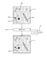
検出過程は図8に方法として示されており、当該方法は、
−組織切片を提供するステップ(811)と、
−分子検出手段を提供するステップ(812)と、
−上記ステップ(1)において開示したように、組織切片を分子検出手段と接触させるステップ(813)と、
−上記ステップ(2)において開示したように、組織切片を洗浄するステップ(814)と、
−上記ステップ(3)において開示したように、適切な基質を添加するステップ(815)と、
−上記ステップ(4)において開示したように、組織切片を洗浄するステップ(816)と、
−上記ステップ(5)において開示したように、組織切片を画像化するステップ(817)と
を含む。
The detection process is shown as a method in FIG.
Providing a tissue section (811);
Providing a molecular detection means (812);
-Contacting the tissue section with the molecular detection means as disclosed in step (1) above (813);
-Washing the tissue section (814) as disclosed in step (2) above;
-Adding an appropriate substrate (815) as disclosed in step (3) above;
-Washing tissue sections (816) as disclosed in step (4) above;
-Imaging a tissue section (817) as disclosed in step (5) above.
821によって示すように、異なる初代細胞型に適した異なる分子検出手段および基質についてステップ812〜817を繰り返すことによって、ステップ817において生成された画像を含む一連の画像が提供される。そのような一連の画像の一例が、より詳細に後述する図4に示されている。
By repeating steps 812-817 for different molecular detection means and substrates suitable for different primary cell types, as indicated by 821, a series of images including the image generated in
検出過程のステップ5に含まれるスキャン/視覚化ステップは、任意の市販のスライドスキャン機器、デジタルカメラを備えた顕微鏡または全面スキャナロボットを用いて実行され得る。 The scanning / visualization step included in step 5 of the detection process can be performed using any commercially available slide scanning instrument, a microscope with a digital camera, or a full scanner robot.
繰り返されるステップ812〜817は、自動的に実行されてもよい。非限定的な例として、いわゆるスライドチャンバ技法が繰り返されるステップに利用されてもよい。スライドチャンバ技法において、組織切片は、分子検出手段、洗浄液などが通過し得るマイクロコンパートメント内に配置される。そのため、組織試料を画像化手段へ、および画像化手段から移動させる必要なしに、種々のステップ812〜817を実行することができる。そのため、組織試料の正確に同じ部分を開示し、同じ焦点深度を有するような、同じ画像特性を有する一次画像を提供することができる。また、方法は、より時間効率的に、かつ手動で操作またはやり取りする必要なしに実行することができる。当業者であれば、本方法は他の自動化技法によっても実行されてもよいことを認識するものである。 Repeated steps 812-817 may be performed automatically. As a non-limiting example, the so-called slide chamber technique may be utilized for repeated steps. In the slide chamber technique, the tissue section is placed in a microcompartment through which molecular detection means, washings, etc. can pass. Thus, the various steps 812-817 can be performed without having to move the tissue sample to and from the imaging means. As such, it is possible to provide a primary image having the same image characteristics, such as disclosing exactly the same portion of the tissue sample and having the same depth of focus. The method can also be performed in a more time efficient manner and without the need for manual manipulation or interaction. One skilled in the art will recognize that the method may be performed by other automated techniques.
検出過程が一連の分子検出手段のすべてについて実行されると、有色点の量が増大した一連の画像が得られる。少量の分子検出手段による処置に対応する第1の画像は、わずかな点しか含まない場合がある。他方、最後の画像は複数の点を含むはずであり、いくつかの点は融合および拡大して大きい有色領域になる可能性もある。 When the detection process is performed for all of the series of molecular detection means, a series of images with an increased amount of colored points is obtained. The first image corresponding to the treatment with a small amount of molecular detection means may contain only a few points. On the other hand, the last image should contain multiple points, some of which can be fused and enlarged into a large colored area.
一実施形態において、一連の画像は、以下の検出過程にしたがって組織切片を画像化することによって提供されてもよい。
(1)組織切片を、結果として前記所定の一連の細胞マーカに特異的に結合する特定の分子検出手段と接触させ、
(2)いかなる細胞表面マーカにも結合されなかった分子検出手段を除去するために組織切片を洗浄し、
(3)一次検出抗体を認識する二次抗体のよな適切な検出試薬を添加する。一般的に、二次抗体は酵素、たとえば、ペルオキシダーゼを用いて標識され、
(4)いかなる細胞マーカにも結合されなかった分子検出手段を除去するために組織切片を洗浄し、
(5)結果として検出可能ポリマーを生成することになる酵素基質を添加し、
(6)残りの基質を除去するために組織切片を洗浄し、
(7)検出可能ポリマーの生成に関連付けられる1つまたは複数の未確定マーカ領域を含み得る一次デジタル画像を生成するために、組織切片をスキャン/画像化する。
In one embodiment, a series of images may be provided by imaging a tissue section according to the following detection process.
(1) contacting the tissue section with specific molecular detection means that specifically binds to the predetermined series of cell markers as a result,
(2) washing the tissue section to remove molecular detection means not bound to any cell surface markers;
(3) An appropriate detection reagent such as a secondary antibody that recognizes the primary detection antibody is added. Generally, the secondary antibody is labeled with an enzyme, such as peroxidase,
(4) washing the tissue section to remove the molecular detection means not bound to any cell marker;
(5) adding an enzyme substrate that results in the production of a detectable polymer;
(6) washing the tissue section to remove the remaining substrate;
(7) Scan / image the tissue section to produce a primary digital image that may include one or more uncertain marker regions associated with the production of the detectable polymer.
上記表1に示すように、いくつかの細胞表面マーカは限られた範囲の細胞と関連付けられ、他のマーカはより広い範囲に現れる。表1において、たとえば、CD20が主にBリンパ球と関連付けられることが留意され得る。対照的に、CD123は大幅により大きい範囲の細胞型と関連付けられる。前記一連の分子検出手段を設定するとき、一連の分子検出手段の始まりにある少量の細胞型、好ましくはただ1つの細胞型のみに対して特異的な分子検出手段を含むことが有利である。その結果、後でより一般的な分子検出手段を使用して細胞型および構造を判定するときに、第1の分子検出手段と関連付けられ、それによって検出される、混同される細胞型および構造を除外することができ、細胞識別の精度が増大する。この情報に基づいて、当業者には適切な一連の分子検出マーカを着想することが容易になる。 As shown in Table 1 above, some cell surface markers are associated with a limited range of cells, while other markers appear in a wider range. In Table 1, it can be noted that, for example, CD20 is primarily associated with B lymphocytes. In contrast, CD123 is associated with a much larger range of cell types. When setting up the series of molecular detection means, it is advantageous to include molecular detection means specific for a small amount of cell types, preferably only one cell type at the beginning of the series of molecular detection means. As a result, when later determining the cell type and structure using a more general molecular detection means, the confused cell types and structures associated with and detected by the first molecular detection means Can be excluded, and the accuracy of cell identification is increased. Based on this information, one of ordinary skill in the art can easily conceive of a suitable set of molecular detection markers.
細胞表面マーカに結合する一連の分子検出手段の以下の例が良好な結果をもたらすことが分かった。 The following examples of a series of molecular detection means that bind to cell surface markers have been found to give good results.
本発明の核心部分は、得られた一連の画像がどのように分析され、新規に編集された画像、ならびに、複数の細胞集団および組織構造と同じ2次元または3次元空間内のそれらの空間的関係を視覚化するための追加の情報を含む3次元描画に変換されるかに関する。 The core of the present invention is how the resulting series of images are analyzed, newly edited images, and their spatial in the same 2D or 3D space as multiple cell populations and tissue structures. Whether it is converted to a 3D drawing containing additional information to visualize the relationship.
これより、本発明の画像分析部分を、以下、本発明の特定の実施形態が図示されている添付の図面を参照しながらより十分に説明する。しかしながら、本発明は、多くの異なる形態において具現化されてもよく、本明細書に記載の実施形態に限定されるものと解釈されるべきではなく、むしろ、これらの実施形態は、本開示が徹底的かつ完全になり、当業者に本発明の範囲を完全に伝達するように例として提供されている。全体を通じて同様の参照符号は同様の要素を指す。 The image analysis portion of the present invention will now be described more fully hereinafter with reference to the accompanying drawings, in which specific embodiments of the invention are shown. However, the present invention may be embodied in many different forms and should not be construed as limited to the embodiments set forth herein; rather, these embodiments are disclosed by this disclosure. It is provided as an example to be thorough and complete and to fully convey the scope of the invention to those skilled in the art. Like reference numerals refer to like elements throughout.
図1は、全体的に符号1を与えられている、本発明による一連の画像内の領域を区別するためのデバイスを示すブロック図である。デバイスは、プロセッサ11とメモリ12とを備える装置10を備える。装置10はコンピュータの一部であり得る。プロセッサ11は、画像内の領域の形状およびロケーションを記録するように構成することができる。形状およびロケーションは、たとえば、メモリ12内のデータベース内の画像に関連付けてまたは関係付けて記憶され得る。プロセッサ11は、所定の選択基準にしたがって画像マーカ領域を識別するために画像を評価するようにさらに構成することができる。プロセッサ11は、2つの画像を比較して、それらの画像の一方には存在するが他方には存在しない画像マーカ領域を識別するようにさらに構成することができる。プロセッサ11はまた、別の画像内の識別された画像マーカ領域と同じ形状およびロケーションを有する新規画像マーカ領域を挿入するように構成することもでき、挿入されたマーカは固有の特徴によって他の画像内で識別可能である。
FIG. 1 is a block diagram illustrating a device for distinguishing regions within a series of images according to the present invention, generally designated 1. The device comprises an
一実施形態において、画像化ユニット13が装置10に接続される。画像化ユニット13は、たとえば、デジタルCCDカメラ、または、スライドスキャナのようなデジタルスキャナである。代替的に、画像化ユニット13を装置10に接続する代わりに、画像を含む、USBのような記憶媒体を接続することによって、装置10に画像を提供することができる。提供された画像はメモリ12内に記憶することができる。
In one embodiment, the
装置10からの出力をユーザに提供するために、出力ユニット14を装置10に接続することができる。出力ユニット14は、たとえば、コンピュータ画面または携帯電話ディスプレイのようなディスプレイである。出力は好ましくは、ソフトウェアインターフェース、すなわち、画像を表示するためのグラフィカルユーザインターフェースの形態である。装置10は好ましくは、ユーザ入力を受信するための入力ユニット15をさらに備える。入力ユニット15の一般的な例は、キーパッドまたはデータ接続手段である。
An
図2aは概して、装置10において実行されてもよい一連の画像内でマーカ領域を区別するための本発明による方法を示す。方法は、以下の、
−所定の選択基準にしたがって画像マーカ領域を画定するために一連の一次デジタル画像を評価する第1のステップ211と、
−先行するステップ211において画定された画像マーカ領域に対応する新規マーカを、マーカが識別可能であるように挿入することによって、一連の画像に基づいて新規画像を作成する第2のステップ212と
を含む。
FIG. 2 a generally illustrates a method according to the present invention for distinguishing marker regions within a series of images that may be performed in
A
-A
ここで、図2bおよび図1を参照して方法を詳細に説明する。 The method will now be described in detail with reference to FIG. 2b and FIG.
ステップ221は、一連のN個の一次デジタル画像I1、I2、...、INを提供することを含み、Nは2以上の整数である。画像は、装置10に接続されている画像化ユニット13によって、または記憶装置(図示せず)によって提供される。
Step 221 includes a series of N primary digital images I 1 , I 2 ,. . . , I N , where N is an integer greater than or equal to two. The images are provided by an
一連のN個の一次デジタル画像は、以下の検出過程(上記でも開示されており、図8によって示されてもいる)にしたがって組織切片を画像化することによって提供される。
(1)組織切片を、結果として前記所定の一連の細胞マーカの特定の成員に特異的に結合する特定の分子検出手段と接触させ、
(2)いかなる細胞マーカにも結合しなかった分子検出手段を除去するために組織切片を洗浄し、
(3)結果として検出可能ポリマーを生成することになる適切な基質を添加し、
(4)残りの基質を除去するために組織切片を洗浄し、
(5)検出可能ポリマーの生成に関連付けられる1つまたは複数の未確定マーカ領域を含み得る一次デジタル画像を生成するために、組織切片をスキャン/画像化する。
A series of N primary digital images is provided by imaging a tissue section according to the following detection process (also disclosed above and also illustrated by FIG. 8).
(1) contacting the tissue section with a specific molecular detection means that specifically binds to a specific member of the predetermined series of cell markers as a result,
(2) washing the tissue section to remove molecular detection means that did not bind to any cell marker;
(3) adding an appropriate substrate that will result in a detectable polymer;
(4) washing the tissue section to remove the remaining substrate;
(5) Scan / image the tissue section to generate a primary digital image that may include one or more uncertain marker regions associated with the generation of the detectable polymer.
検出過程は所望の回数繰り返される。ステップ5(図8におけるステップ817に対応する)は過程サイクルごとに一次デジタル画像を生成する。したがって、N回のサイクルによって一連のN個の画像が生成される。 The detection process is repeated as many times as desired. Step 5 (corresponding to step 817 in FIG. 8) generates a primary digital image for each process cycle. Therefore, a series of N images is generated by N cycles.
この過程は画像を生成し、画像In+1が少なくとも、画像In(2≦n≦N)と同じ量の未確定画像マーカ領域を備え、nは整数である。それによって、一連の画像は、増大していく量の未確定マーカ領域を備え、画像INが最大量の未確定マーカ領域を備え、I1が最小量の未確定マーカ領域を備える。 This process produces an image, where image I n + 1 comprises at least as many uncertain image marker regions as image I n (2 ≦ n ≦ N), where n is an integer. Thereby, the series of images comprises an increasing amount of undetermined marker areas, image IN with the largest amount of undetermined marker areas, and I 1 with the smallest amount of undetermined marker areas.
次に、ステップ222は、所定の選択基準にしたがってすべての画像In(1≦n≦N)を評価し、画像マーカ領域を画定することを含む。特に、未確定マーカ領域が評価される。画像内の所定の選択基準を満たす領域が画像マーカ領域として画定される。上記の定義節においてすでに述べたように、一般的にサイズ基準、形状基準および色基準があり得る。選択基準は評価過程の結果に大きく影響する。たとえば、サイズに関する比較できるほどに高い閾値レベルによって、評価するのが容易であるより明瞭な画像がもたらされ得るが、サイズがより小さい関連構造が検出されなく成るという危険性が常にある。それゆえ、選択基準を決定するとき、研究しようとしている組織型の切片内に通常存在する細胞および細胞構造に関するデータを考慮することが好ましい。当業者はこの知識を有する。
Next,
領域は、1つまたは複数のピクセルを含む。領域はさらに、画像内の複数の隣接するピクセルとして画定され得る。どのように領域が画定されるかは所定の選択基準の一部であり得る。基準は、たとえば、21ピクセル以上から成る領域のみが画像マーカ領域として画定されるべきであるという基準を含み得る。別の基準は、領域を形成するピクセルは特定の形状に類似すべきであるというものであり得る。ステップ222は図2a内のステップ211に対応する。 A region includes one or more pixels. A region can be further defined as a plurality of adjacent pixels in the image. How the region is defined can be part of a predetermined selection criterion. The criteria may include, for example, a criterion that only regions consisting of 21 pixels or more should be defined as image marker regions. Another criterion may be that the pixels forming the region should resemble a particular shape. Step 222 corresponds to step 211 in FIG. 2a.
ステップ223は、新規の二次デジタル画像Inewを提供することを含む。新規画像は、一連の画像と同じ対象を表し得る。特に、新規画像は、一連の画像内の一次デジタル画像のうちの1つのコピーであってもよい。そのような実施形態では、Inewは、一連の画像内の画像のうちの1つをコピーすることによって作成されてもよい。 Step 223 includes providing a new secondary digital image Inew . A new image may represent the same object as a series of images. In particular, the new image may be a copy of the primary digital image in the series of images. In such an embodiment, I new may be created by copying one of the images in a series of images.
有利には、新規画像は、可能な限り元の組織試料に近い、すなわち、任意の検出過程サイクルの前の組織試料を表す。これは、第1の検出過程サイクルが実行される前に組織切片を画像化し、したがって画像I0を作成することによって達成され得る。そのような実施形態では、画像10は一連の画像を提供するステップ221の前のステップにおいて提供され得る。
Advantageously, the new image represents the tissue sample as close as possible to the original tissue sample, ie before any detection process cycle. This may be achieved by first detection process cycle to image the tissue section prior to being executed, thus creating an image I 0. In such embodiments,
代替的に、新規画像は空白画像であってもよく、すなわち、内容物が一切なくてもよい。空白画像はプロセッサ11によって作成することができる。空白画像とは、たとえば、すべてのピクセル値、たとえば、RGB値がゼロにセットされている画像を意味する。
Alternatively, the new image may be a blank image, i.e. without any content. A blank image can be created by the
別の代替的な実施形態において、新規画像は、ヘマトキシリンのような標準的な対比染色剤、または、組織背景に関する有益な情報を提供し後続の免疫組織染色および検出工程を妨げない任意の他の染色剤を用いて組織試料を最初に染色した後の画像をキャプチャすることによって提供される。 In another alternative embodiment, the new image is a standard counterstain such as hematoxylin, or any other that provides useful information about the tissue background and does not interfere with subsequent immunohistochemical staining and detection steps. Provided by capturing an image after the initial staining of the tissue sample with a stain.
新規画像は、たとえば、画像化ユニットから、またはメモリユニットから提供され得ること、および、方法はこれらの代替形態のいずれにも限定されないことが留意されるべきである。 It should be noted that the new image can be provided, for example, from an imaging unit or from a memory unit, and the method is not limited to any of these alternatives.
新規画像マーカ領域は任意の順序でInew内に挿入されてもよい。 New image marker areas may be inserted into Inew in any order.
新規画像Inewを提供するステップ223は、すべての画像を評価するステップ222の前に、または、一連の画像を提供するステップ221の前に実行されてもよく、すなわち、新規画像を提供するステップはそれに先行するステップに依存しないことが留意されるべきである。
Providing a new image I new 223 may be performed before the
ステップ224は新規画像Inew内に新規画像マーカ領域を挿入することを含む。すべての画像In(2≦n≦N)について、画像In内には存在するが画像In−1内には存在しない画像マーカ領域と同じ形状およびロケーションを有する新規画像マーカ領域がInew内に挿入される。これは、各画像をその後続の画像In−1と比較し、Inには存在するがIn−1には存在しない画像マーカ領域を識別することによって達成される。nについての評価は一定の順序で実行する必要はなく、事実、適切であると分かったいずれの順序でも実行することができる。しかしながら、一連の画像内の画像の順序は保持されること、および、画像In内には存在するが画像In−1内には存在しない画像マーカ領域のみが識別されることが重要である。 Step 224 includes inserting the new image marker area in the new image I in new. For all the images I n (2 ≦ n ≦ N ), the new image marker area having the same shape and location as the image marker area which is not present in existing in the image I n is the image I n-1 is I new new Inserted inside. This each image compared to its subsequent image I n-1, is present in I n is accomplished by identifying the image marker area which is not present in the I n-1. The evaluation for n need not be performed in a fixed order, and in fact can be performed in any order found to be appropriate. However, the order of images in a sequence of images is maintained, and it is important that only the image marker area is not present is identified in the image I n-1 is present in the image I n .
新規画像と同じ形状およびロケーションを有する画像マーカ領域を比較および挿入する方法は、当業者にすべて既知である多くの様式で実行されてもよい。例としては、データベース内に形状および/またはロケーションを記憶し、画像編集ソフトウェアのコピー−ペースト機能を使用することである。ステップ224を、図4〜図5に関連してさらに説明する。 The method of comparing and inserting image marker regions having the same shape and location as the new image may be performed in many ways that are all known to those skilled in the art. An example is to store the shape and / or location in a database and use the copy-paste function of the image editing software. Step 224 is further described in connection with FIGS.
Inew内に挿入される画像マーカ領域はさらに、固有の特徴、特に固有の特徴の固有値によってInew内で識別可能にされる。識別可能な特徴は、Inew内には元々存在しない特徴であり、たとえば、色であり得る。この場合、色の固有値は特定の、かつ固有のニュアンスであり得る。この値は、画像Inを生成する検出過程サイクルに使用される特定の分子検出手段に対して固有であり、それゆえ、対応する要素または構造に対して固有であることが重要である。固有の特徴/値の目的は、それらが、検出過程の異なるサイクルに由来する異なる画像マーカ、および、したがって組織切片の異なる要素/初代細胞および構造に対する異なる分子検出手段を区別することである。一実施形態において、固有の特徴は新規画像内の視覚的マーカである。一実施形態において、固有の特徴は一般色であり、固有の特徴の固有値は、特定の細胞マーカに関連付けられる特異的な色である。 Image marker regions inserted in I new are further made identifiable in I new by unique features, in particular by the unique values of the unique features. Identifiable feature, the inside I new new is originally nonexistent features, for example, be a color. In this case, the eigenvalue of the color can be a specific and unique nuance. This value is unique to the particular molecule detection means used in the detection process cycle of generating an image I n, therefore, it is important that the unique for the corresponding elements or structures. The purpose of the unique features / values is that they differentiate between different image markers from different cycles of the detection process, and thus different molecular detection means for different elements / primary cells and structures of the tissue section. In one embodiment, the unique feature is a visual marker in the new image. In one embodiment, the unique feature is a general color and the unique value of the unique feature is a specific color associated with a particular cell marker.
別の実施形態において、Inに由来する画像マーカ領域の固有の特徴は、画像マーカ領域と、検出過程のサイクルnにおいてマーキング対象とされる、対応する要素および/または構造との間のデジタルな関連付け/関係である。関連付け/関係は、メモリ12内の関連データベース内などに、画像Inに関連/関係付けて記憶される。
In another embodiment, the unique features of the image marker region from I n includes an image marker area, are marked interest in cycle n of the detection process, digital between the corresponding elements and / or structures Association / relationship. Association / relationship in such a relational database in
これより、所定の選択基準にしたがって画像マーカ領域を画定するために一連の画像を評価するステップ211を図3を参照して説明する。
A
図3は、組織切片を表す一次デジタル画像を示す。画像は、上記で開示した、図8に示すような検出過程のあるサイクルに由来する。I1aは、組織切片の要素および構造に対応する種々の要素および構造を含む。教授する上での理由から、組織試料の要素および構造は図3において単純化された幾何形状として表されている。現実には、画像は一般的に数千の要素および構造を含む。 FIG. 3 shows a primary digital image representing a tissue section. The images are derived from a cycle of the detection process disclosed above, as shown in FIG. I 1a includes various elements and structures corresponding to the elements and structures of the tissue section. For teaching purposes, the elements and structures of the tissue sample are represented as simplified geometries in FIG. In reality, images typically contain thousands of elements and structures.
この例において、検出過程は、検出可能ポリマーの生成が、ポリマーが生成される領域内に色の遷移をもたらすように選択されている。色の遷移は、領域がより暗くなるようなものである。検出過程(図8のステップ815)の影響を受けるとき、検出可能ポリマーの生成が引き起こされた領域は未確定マーカ領域と称される。図3において、未確定マーカ領域は31a、32a、33aおよび34aによって示されている。 In this example, the detection process is selected such that the production of the detectable polymer results in a color transition in the region where the polymer is produced. The color transition is such that the area becomes darker. When affected by the detection process (step 815 in FIG. 8), the region that caused the production of detectable polymer is referred to as the indeterminate marker region. In FIG. 3, the undetermined marker regions are indicated by 31a, 32a, 33a and 34a.
これらの領域は検出可能ポリマーによって生成されるため、それらはポリマーを検出することによって識別することができる。 Since these regions are generated by a detectable polymer, they can be identified by detecting the polymer.
本実施例では、領域内で検出可能ポリマーがより多く生成されると、領域はより暗くなる。理想的な検出過程では、検出可能ポリマーの生成は、特定の分子検出手段を選択するときに対象とされている要素に関連してのみ存在する。しかしながら、検出可能ポリマーは、検出抗体(または分子検出に使用される構成要素)の交差反応および非特異的結合にも起因して他の領域においても生成されることが多い。画像は、検出過程によって影響を受けていないさらなる未確定マーカ領域を含み得る。「真の」要素および構造、すなわち、特定の検出過程サイクルにおいてマーキングされるように意図されている要素および構造に由来する可能性が最も高い領域を選別することが所望される。それゆえ、一連の画像内の各画像は、所定の選択基準にしたがって、図3のステップ310に示すように評価される。選択基準は、特定の検出過程に適するように選択される。
In this example, the region becomes darker as more detectable polymer is produced in the region. In an ideal detection process, the production of a detectable polymer exists only in relation to the element that is of interest when selecting a particular molecular detection means. However, detectable polymers are often generated in other regions due to cross-reactivity and non-specific binding of detection antibodies (or components used for molecular detection). The image may include additional indeterminate marker regions that are not affected by the detection process. It is desirable to screen for “true” elements and structures, ie, areas most likely to come from elements and structures that are intended to be marked in a particular detection process cycle. Therefore, each image in the series is evaluated as shown in
選択基準は、以下のような複数の副基準を含んでもよい。
−色閾値
−色間隔
−幾何学的特性(形状およびサイズのパラメータ)
−マーキング領域内の染色パターンの性質(たとえば、粒度、粗大化、滑らかで均一な染色、点状染色などのテクスチャパラメータ)。
−ロケーション(たとえば、例として非染色切片においてすでに識別されている可能性があるか、または背景組織染色の後の組織構造に関連する)。
The selection criteria may include a plurality of sub-criteria as follows.
-Color threshold-Color spacing-Geometric properties (shape and size parameters)
-The nature of the staining pattern in the marking area (e.g. texture parameters such as grain size, coarsening, smooth and uniform staining, punctate staining).
-Location (eg it may have already been identified in non-stained sections as an example or related to histology after background tissue staining).
これらのまたは類似の基準を使用して画像を評価することは当業者には既知であり、米国の国立衛生研究所(NIH)によって提供されるImageJ、米国のMedia Cybernetica IncによるImage−Pro Plus、デンマークのisiopharm A/SによるVisiomorph、ドイツのDefiniens AGによるDefiniens Tissue Studio、米国のAperio TechnologiesによるGenie、米国のMathworks IncによるMATLAB、Adobe Photoshopなどのようなソフトウェアを使用して為され得る。 Assessing images using these or similar criteria is known to those skilled in the art, ImageJ provided by the National Institutes of Health (NIH), Image-Pro Plus by Media Cyberneta Inc, USA, Visiomorph by Danish isopharm A / S, Definiens Tissue Studio by Definiens AG in Germany, Genie by Aperio Technologies in the United States, and MATB by Adh by Mathworks Inc in the United States
色閾値とは、HLS(色相、彩度、飽和)カラースケールのようなカラースケールにおける閾値を意味し、特定のカラースケールの閾値を上回るまたは下回る色値を有するピクセルが選択副基準を満たす。 By color threshold is meant a threshold in a color scale, such as the HLS (Hue, Saturation, Saturation) color scale, and pixels having color values above or below a particular color scale threshold satisfy the selection sub-criteria.
色間隔とは、200〜230のような、特定の間隔内にあるRGBカラースケール画像のR値のような、カラースケール内の間隔を意味する。ピクセルがその間隔内のピクセル値を有する領域が選択副基準を満たす。 A color interval means an interval in the color scale, such as an R value of an RGB color scale image within a specific interval, such as 200-230. The region where the pixel has a pixel value within that interval satisfies the selection sub-criteria.
色閾値および色間隔基準は、HSBカラースケールまたはHISカラースケールのような他のカラースケールでも同様に適用可能である。当業者に既知であるような多くの他のカラースケールも存在する。 The color threshold and color spacing criteria are equally applicable with other color scales such as the HSB color scale or the HIS color scale. There are many other color scales as known to those skilled in the art.
幾何学的特性とは、領域の形状および/またはサイズに関連付けられるパラメータを意味する。例としては、丸み、真円度、長さ、不規則性パラメータなどである。真の要素/構造を、それらの形状によって真でない要素/構造から画定するために形状値基準を使用することができる。たとえば、神経は細長い形状を有し、それによって、細長い形状以外の形状を有する、神経に対する検出過程から生じる未確定マーカ領域は、特定の画像の画像マーカ領域として画定されるものから除外することができる。 By geometric property is meant a parameter associated with the shape and / or size of the region. Examples are roundness, roundness, length, irregularity parameters, etc. Shape value criteria can be used to define true elements / structures from elements / structures that are not true by their shape. For example, nerves have an elongated shape, so that indeterminate marker regions resulting from a detection process for nerves that have a shape other than an elongated shape may be excluded from what is defined as an image marker region for a particular image. it can.
当業者には理解されるように、他の適切な型の選択基準も本発明において使用されてもよい。適切であるとは、選択基準が、特定の対応する検出過程サイクルにおいて対象とされている要素および構造に由来する可能性が最も高い未確定マーカ領域を選別するように適合されていることを意味する。 As will be appreciated by those skilled in the art, other suitable types of selection criteria may also be used in the present invention. Appropriate means that the selection criteria are adapted to screen the indeterminate marker regions most likely to be derived from the elements and structures of interest in a particular corresponding detection process cycle. To do.
一実施形態において、選択基準は、色、テクスチャ、サイズ、または丸みのような、視覚的特性に対する閾値を含む。視覚的特性とは、マーカ領域の何らかの種類の外観的特性を意味する。特性は、視覚的特性であるためにたとえば、出力ユニット上で視覚化される必要はないことに留意されたい。 In one embodiment, the selection criteria includes a threshold for visual characteristics, such as color, texture, size, or roundness. By visual characteristic is meant some kind of visual characteristic of the marker area. Note that the characteristic does not need to be visualized on the output unit, for example, to be a visual characteristic.
選択基準は、上述の基準型のうちの1つまたは複数を含んでもよい。色閾値基準と形状値基準との組合せのような異なる型の基準の組合せも含まれてもよく、画像マーカ領域として画定されるためには両方の基準が未確定マーカ領域によって満たされなければならない。 Selection criteria may include one or more of the criteria types described above. A combination of different types of criteria, such as a combination of color threshold criteria and shape value criteria, may also be included and both criteria must be met by an indeterminate marker region in order to be defined as an image marker region .
この例において、選択基準は視覚的特性、より詳細には色閾値を含む。十分に暗い色を有する領域のみが画像マーカ領域として画定され、したがって「真の」要素および構造と相関すると考えられる。この例はグレースケール色のみを含むため、色閾値はグレースケール上の一定の値よりも高い強度を有するすべてのピクセルにセットされ得る。0が黒に対応し1が白に対応する0〜1のグレースケールにおいて、0.75の閾値がセットされてもよい。別のカラースケール、たとえば、RGBカラースケールの画像を含む他の実施形態において、閾値は当業者に理解されるような対応する方法でセットされてもよい。 In this example, the selection criteria include visual characteristics, more specifically color thresholds. Only regions with a sufficiently dark color are defined as image marker regions and are therefore considered to correlate with “true” elements and structures. Since this example includes only grayscale colors, the color threshold can be set for all pixels having an intensity higher than a certain value on the grayscale. A threshold of 0.75 may be set in a gray scale of 0 to 1 where 0 corresponds to black and 1 corresponds to white. In other embodiments involving images of other color scales, eg, RGB color scale, the threshold may be set in a corresponding manner as will be understood by those skilled in the art.
異なる選択基準によって異なる評価結果、および、したがって異なる二次画像がもたらされる。図3の本実施例において、選択基準は未確定マーカ領域のピクセルがグレースケール色閾値を上回らなければならないということを含む。評価によって、画像マーカ領域31bを有する二次デジタル画像bが得られる。画像マーカ領域31bは、選択基準を満たす未確定マーカ領域31aを評価することによって画定される。他の未確定マーカ領域32a、33a、34aは選択基準を満たしておらず、そのため画像マーカ領域として画定されない。追加のステップ311において、たとえば、評価されたマーカ領域の幾何空間パラメータ(座標)または形状インデックスを含む評価の情報が、二次画像b内に、または、関連データベース内のように、それに関係/関連付けて記憶される。そのようなデータベースは、画像マーカ領域として画定されている未確定マーカ領域に関連する情報を用いて後に更新されてもよい。情報は、ステップ224において新規画像内に新規画像マーカ領域を挿入するのに使用することができる。
Different selection criteria result in different evaluation results and thus different secondary images. In the present embodiment of FIG. 3, the selection criteria include that the pixels in the indeterminate marker region must exceed the grayscale color threshold. By the evaluation, a secondary digital image b having an
画像I1bは、I1aと正確に同じ画像であってもよく、または、コピーおよび/もしくは、画像マーカ領域によって視覚的マークを挿入することなどによってデジタル的に編集されてもよい。しかしながら、二次デジタル画像は、一次デジタル画像と同じ画像であることには限定されない。 Image I 1b may be exactly the same image as I 1a , or may be edited digitally, such as by copying and / or inserting a visual mark with an image marker area. However, the secondary digital image is not limited to being the same image as the primary digital image.
二次デジタル画像と一次デジタル画像との間の差は、二次デジタル画像が画像マーカ領域を画定するために評価されている一方で、一次デジタル画像は未加工の編集されておらず評価されていないデータであることである。本方法における任意の編集または作成されたデジタル画像は、デジタル画像化またはスキャンから直接得られるいかなる未加工画像でもないため、二次画像と称される。それゆえ、たとえば、本発明のステップ212および224において作成される新規画像も、二次デジタル画像と称される。
The difference between the secondary digital image and the primary digital image is evaluated while the secondary digital image is evaluated to define the image marker area, while the primary digital image is evaluated without raw editing. There is no data. Any edited or created digital image in this method is referred to as a secondary image because it is not any raw image obtained directly from digital imaging or scanning. Thus, for example, new images created in
一実施形態において、ユーザは、画像ソフトウェアを使用し、一定の色強度、ロケーション、周囲状況および/または形状のような所定の選択基準にしたがって画像マーカ領域を画定することによって、一次デジタル画像を評価してもよい。この種の評価に有用な画像ソフトウェアの例は、米国のMedia Cybernetica IncによるImage−Pro Plus、デンマークのVisiopharm A/SによるVisiomorph、ドイツのDefiniens AGによるDefiniens Tissue Studio、および米国のMathworks IncによるMatlabである。 In one embodiment, the user uses the image software to evaluate the primary digital image by defining image marker regions according to predetermined selection criteria such as constant color intensity, location, ambient conditions and / or shape. May be. Examples of imaging software useful for this type of evaluation are Image-Pro Plus by Media Cyberneta Inc., USA, Visiomorph by Visiopharmam A / S, Denmark, Definiens Tissue Studio by Definiens AG, Germany, and a is there.
これより、画定された画像マーカ領域に対応する識別可能な分類された新規マーカを挿入することによって新規画像を作成するステップ212を図4を参照して説明する。
The
図4は、本発明の一実施形態の画像系列を開示している。画像I1、I2、I3、I4が一連のN個の画像を形成しており、N=4である。各画像内の描画されている対象物は組織切片(または組織切片の一部)である。各画像は同じ組織切片(の同じ部分)を含む。画像は各々、ステップ211およびステップ222にしたがって評価されている。 FIG. 4 discloses an image sequence according to an embodiment of the present invention. Images I 1 , I 2 , I 3 , and I 4 form a series of N images, where N = 4. The object drawn in each image is a tissue section (or part of a tissue section). Each image contains the same tissue section. The images are evaluated according to step 211 and step 222, respectively.
各画像は画像マーカ領域を含み、すなわち、I1は画像マーカ領域411aを含み、I2は画像マーカ領域411bおよび421aを含み、I3は画像マーカ領域411c、421b、431a、および432aを含み、I4は画像マーカ領域411d、421c、431b、432b、441a、および442aを含む。ロケーションパラメータ、形状パラメータ、色値、強度値などのような画像マーカ領域に関する情報が、好ましくは、画像自体の中に、または、画像に関連付けられているデータベース内のように、画像自体に関係/関連付けられて記憶されている。そのようなデータベースはメモリ12内に配置することができる。パラメータはたとえば、図3のステップ311(上述)にしたがって記憶される。
Each image includes an image marker region, ie, I 1 includes an
すでに開示されたように、画像系列内の画像は少なくとも同じ、または一般的には増大していく量の画像マーカ領域を含む。I4は最大量の画像マーカ領域を含み、I1は最小量の画像マーカ領域を含む。Inは少なくともIn−1(n=2、3または4)と同じ量の画像マーカ領域を含む。 As previously disclosed, the images in the image sequence include at least the same or generally increasing amounts of image marker regions. I 4 contains the maximum amount of image marker area and I 1 contains the minimum amount of image marker area. I n includes an image marker area of at least I n-1 (n = 2,3 or 4) and the same amount.
I4、I3および/または関連データベース内のそれらに関連する情報を比較することによって、画像マーカ領域441aおよび442aはI4内には存在するがI3内には存在しないことが分かる。したがって、画像マーカ領域441aおよび442aと同じ形状およびロケーションを有する新規画像マーカ領域が、ステップ224にしたがってInew内に挿入される。新規画像マーカ領域はさらに、固有の特徴、特に固有の特徴の固有値によって識別可能にされる。
By comparing I 4 , I 3 and / or information related to them in the related database, it can be seen that
図5aおよび図5bに、新規画像の例が与えられている。これらは本実施例において得ることができる。図5a内の新規画像Inewは、画像I1〜I4のうちの1つ、たとえばI1をコピーすることによって提供される。図5bにおいて、新規画像Inewが、空白画像、すなわち、何ら情報を有しない画像を作成することによって提供される。
An example of a new image is given in FIGS. 5a and 5b. These can be obtained in this embodiment. New image I new new in FIG. 5a, one of the
上記で開示したように、画像マーカ領域441aおよび442aと同じ形状およびロケーションを有する新規画像マーカ領域が挿入される。図5a〜図5bにおいて、これらは541および542として参照される。
As disclosed above, a new image marker region having the same shape and location as the
図5a〜図5bにおいて、固有の特徴は視覚マーカであり、特異的なグループの挿入されている画像マーカ領域に固有のパターンを含む。画像マーカ領域541および542は、I3の画像化とI4の画像化との間の検出過程サイクルにおいてマークされているグループ領域に属する。画像マーカ領域541および542について、固有の特徴の視覚マーカは点状パターンである。
In FIGS. 5 a-5 b, the unique feature is a visual marker, which includes a unique pattern in the specific group of inserted image marker regions.
画像マーカ領域441aおよび442aと同じ形状およびロケーションを有する画像マーカ領域541および542を挿入するために、データベースは、画像マーカ領域441aおよび442aを参照する情報を含んでもよい。上記で開示したように、そのような情報は、図3の追加のステップ311においてデータベース内に記憶されてもよい。さらに、図2bによる方法は、所定の選択基準にしたがって識別された各画像マーカ領域の形状およびロケーションを記録する追加のステップを含んでもよい。画像マーカ領域441aおよび442bの形状およびロケーションを知ることによって、新規画像マーカ領域541および542を挿入することができる。当業者であれば理解し得るように、新規画像マーカ領域は、当該技術分野において一般的に既知である他の手順によって新規画像内に挿入することができる。
In order to insert
I3をI2と比較することによって、画像マーカ領域431aおよび432aがI3内には存在するが、I2内には存在しないものとして識別される。画像マーカ領域431aおよび432aと同じ形状およびロケーションを有する新規画像マーカ領域531および532が、Inew内に挿入される。図5a〜図5bにおいて、531および532の固有の特徴の視覚マーカは塗りつぶしパターンである。
The I 3 by comparing the I 2, the
I2をI1と比較することによって、画像マーカ領域421aがI2内には存在するが、I1内には存在しないものとして識別される。画像マーカ領域521aと同じ形状およびロケーションを有する新規画像マーカ領域521が、Inew内に挿入される。図5aおよび図5bにおいて、521の固有の特徴の視覚マーカは線入りパターンである。
By comparing I 2 with I 1 ,
I1は検出過程の第1のサイクルの結果であるため、いかなる他の画像とも比較する必要はない。この例において、画像マーカ領域411aは、I1内に存在するものとして識別され、したがって、I1を生成する検出過程サイクルに由来する。411aと同じ形状およびロケーションを有する新規マーカ領域511がInew内に挿入される。画像マーカ領域511はさらに、固有の特徴にしたがって識別可能にされる。図5aおよび図5bにおいて、画像マーカ領域511の固有の特徴の視覚マーカは正方形パターンである。
Since I 1 is the result of the first cycle of the detection process, there is no need to compare with any other images. In this example, the
それによって、分類された画像マーカ領域を含む新規画像が作成されており、それにしたがって、各画像マーカが検出サイクル、ならびに、それゆえ細胞マーカおよび初代細胞を表す。本発明の方法によって、複数の細胞または組織構造が同じ型の検出過程の反復を使用して識別および分類され得る。検出可能ポリマーまたは蛍光色素のような、組織要素または構造をマークするのに使用されるマーカはそれら自体が固有である必要はない。特異的な波長を有する単一の型の検出可能ポリマーまたは蛍光色素が、検出過程のすべてのサイクルに使用され、同じ強度、色または発光波長を有するマーカ領域を生成してもよい。この利点は、図4の画像I4および、たとえば、図5aのInewによって示される。既知の技法によって、複数回の検出過程の結果、画像I4が生成される。ここで、マーカ領域を互いから区別することは不可能である、すなわち、I4内の画像領域がいずれの型の初代細胞または組織構造を表すかを知ることは可能ではない。しかしながら、複数回の画像化が開示されている画像分析方法と組み合わされている本発明の新規の概念によって、分類を有する画像マーカ領域を含む画像を、単純かつ効率的な方法で達成することができる。したがって、同じ切片内で複数のマーカを検出することの制限のような、既知の方法に伴う多くの問題を克服することができる。 Thereby, a new image is created that includes the classified image marker region, and accordingly each image marker represents a detection cycle, and hence a cell marker and primary cell. By the method of the present invention, multiple cells or tissue structures can be identified and classified using the same type of iteration of the detection process. Markers used to mark tissue elements or structures, such as detectable polymers or fluorescent dyes, need not be unique per se. A single type of detectable polymer or fluorescent dye with a specific wavelength may be used for every cycle of the detection process to produce a marker region with the same intensity, color or emission wavelength. This advantage is illustrated by image I 4 in FIG. 4 and, for example, I new in FIG. 5a. According to known techniques, an image I 4 is generated as a result of multiple detection processes. Here, it is impossible to distinguish the marker areas from each other, ie it is not possible to know what type of primary cell or tissue structure the image area in I 4 represents. However, the novel concept of the present invention combined with multiple disclosed imaging analysis methods allows to achieve an image including image marker regions with classification in a simple and efficient manner. it can. Thus, many of the problems associated with known methods, such as the limitation of detecting multiple markers within the same section, can be overcome.
図6a〜図6bは、本発明による、画像Inew内の分類された画像マーカ領域のための固有の視覚的特徴の例を示す。画像は、要素および構造を有する組織試料を表す。画像は、本発明の方法を通じて提供されている。 6a-6b show examples of unique visual features for classified image marker regions in image I new according to the present invention. The image represents a tissue sample having elements and structures. Images are provided through the method of the present invention.
図6aにおいて、固有の特徴は異なるパターンである。 In FIG. 6a, the unique features are different patterns.
図6bにおいて、固有の特徴はグレーの色であり、固有値はグレーカラーの強度、特に異なるグレースケール強度である。新規画像は、異なる色のような複数の特徴を含み、当該色はさらに固有値に細分化され得、その値は前記異なる色の異なる強度であり得る。 In FIG. 6b, the characteristic feature is a gray color, and the characteristic value is the intensity of the gray color, in particular the different gray scale intensity. The new image includes multiple features, such as different colors, which can be further subdivided into eigenvalues, which can be different intensities of the different colors.
図6cにおいて、固有の特徴は異なる符号である。この実施形態において、記号は文字であるが、それらはまた、数字、幾何学記号など、またはそれらの組合せであってもよい。記号は、デジタル画像Inew内でそれが表す画像マーカ領域付近に配置され、それによって、いずれの画像マーカがそれに関連付けられているかが明瞭である。 In FIG. 6c, the unique features are different symbols. In this embodiment, the symbols are letters, but they may also be numbers, geometric symbols, etc., or combinations thereof. Symbol is placed in the image marker near region it represents a digital image I within new new, whereby, either visual markers are associated with it are clear.
前述のように、固有の特徴は必ずしも新規画像内に配置された視覚的特徴である必要はないことが留意されるべきである。その代わりに、それと組み合わせて、視覚マーカは固有のデジタル値のようなデジタル情報であってもよく、あるグループの画像マーカ領域が互いに関連付けられる。そのような情報は、データベース内に、好ましくは、画像マーカ領域のロケーション、形状、および他の染色特性に関連する情報を含む上述のデータベース内に記憶されてもよい。 As noted above, it should be noted that the unique features do not necessarily have to be visual features placed in the new image. Instead, in combination, the visual marker may be digital information, such as a unique digital value, and a group of image marker regions are associated with each other. Such information may be stored in a database, preferably in the above-described database that includes information related to the location, shape, and other staining characteristics of the image marker region.
図7は、本発明の一実施形態を示し、全体的に符号7を与えられているグラフィカルインターフェースが、ユーザに本発明の方法に関連する情報を提供するのに使用される。グラフィカルインターフェース7を提供するコンピュータプログラムがメモリ12内に記憶され、プロセッサ11によって実行され得る。コンピュータプログラムは、代替的に、USBスティックまたはCD−ROMのような、任意の適切な記憶装置上に記憶されてもよい。コンピュータプログラムはさらに、本発明による、一連の画像内でマーカ領域を区別する方法を実行することができる。
FIG. 7 illustrates one embodiment of the present invention, and a graphical interface, generally designated 7, is used to provide the user with information related to the method of the present invention. A computer program providing the graphical interface 7 can be stored in the
グラフィカルインターフェース7は、装置10に接続されている、コンピュータ画面のような出力ユニット14を通じてユーザに提示されるグラフィカルウィンドウ71を備える。ユーザは、装置10に接続されている、コンピュータマウスまたはキーボードのような入力ユニット15によって、選択のような入力をコンピュータプログラムに提供することができる。
The graphical interface 7 comprises a
グラフィカルウィンドウ71は、本発明による方法によって提供される新規画像Inewに対応する画像72を含む。この実施形態において、画像72は、図4〜図5内のものと同じ組織切片を表す。
The
グラフィカルウィンドウ71は、画像72の見え方を適応させるための少なくとも1つのボックス75をさらに含む。ボックス75は、異なる複数の選択肢の間での選択を提供するための選択ボックス76を含んでもよい。この実施形態において、ボックス75は、いずれの群の初代細胞集団を画像72内で強調するかの選択を提供する。選択ボックス76内で選択肢「Bリンパ球」を選択することによって、Bリンパ球に関連付けられる画像マーカ領域751および752が強調される。画像マーカ領域と初代細胞との間の関連付けはデータベース内に記憶されてもよく、関連付けに関する情報はコンピュータプログラムによってデータベースから得ることができる。データベースは、上記で開示したような本発明による方法によって、特にステップ311によって達成することができる。ボックス75によって提供される選択肢は、1つのみの型の細胞型を含むようには限定されず、複数の細胞型からなる群も同様に等しく含み得る。
The
グラフィカルウィンドウ71は、複数の選択ボックス、または、チェックボックス、複数の選択ウィンドウなどのような他の適切な適応手段をさらに含んでもよい。
The
グラフィカルウィンドウ71は、情報ボックス79に関連付けられるボックス77をさらに含む。情報ボックスにおいて提供される情報は、画像72の画像マーカ領域に関連付けられる。情報は、画像72の画像マーカ領域に関連する情報を含むデータベースによって得ることができる。選択ボックス77は選択ボックス78を含む。ユーザは、情報ボックス79内に画像マーカ領域に関する特定のそのような情報を示すために、異なる情報型の間で選択することができる。この示されている例において、ユーザは、選択ボックス78内で「x,Y座標」を選択することによって、座標を示すことを選択している。選択ボックス76によって選択されている、強調されている画像マーカ領域751および752のxおよびy座標に関連する情報は、情報ボックス79によって提供される。
The
無論、グラフィカルインターフェース7は多くの異なる形態をとり、多くの異なる機能を含んでもよい。したがって、グラフィカルインターフェース7によってユーザに提供することができる、画像マーカ領域に関連する情報の型は、この例によって限定されない。特許請求する方法によって、ユーザに以下のような情報を提供することができる。
−たとえば、μm2単位で表される、任意のマーカ領域の面積。
−画像マーカ領域の形状値、たとえば、周および丸み
−強度値、たとえば、画像マーカ領域内のピクセルの平均強度値
−画像内の距離、たとえば、2つの画像マーカ領域間の距離
−画像マーカ領域、またはマーカ領域のグループの間の空間相関、たとえば、ソフトウェア内の統計アルゴリズムを使用することによって、ユーザは、たとえば、Bリンパ球に対応するマーカ領域と、たとえばTリンパ球の細胞集団に対応する同じ組織領域ニアのマーカ領域との間の空間的関係に関する情報を得ることができる。
Of course, the graphical interface 7 may take many different forms and include many different functions. Thus, the type of information related to the image marker area that can be provided to the user by the graphical interface 7 is not limited by this example. According to the claimed method, the following information can be provided to the user.
The area of any marker region, eg expressed in μm 2 units.
-Shape value of the image marker area, e.g. circumference and roundness-intensity value, e.g. average intensity value of pixels in the image marker area-distance in the image, e.g. distance between two image marker areas-image marker area, Or, by using a spatial correlation between groups of marker regions, eg, statistical algorithms in software, the user can, for example, have the same marker region corresponding to B lymphocytes and the same cell population corresponding to T lymphocytes, for example. Information regarding the spatial relationship between the marker region of the tissue region near can be obtained.
連続して切断した組織切片(たとえば、各々がたとえば4μm2の固定厚さを有する20個の連続した切片)に本発明を適用するとき、図7に示すもののような同様のグラフィカルインターフェースが、3D画像において画像マーカ領域の3次元分布を表示することもできることが留意されるべきである。同様に、このときユーザは、画像マーカ領域に関する、それらのx、y、およびz座標のような3D情報を得ることができる。3Dレンダリングについて一般的に既知であるアルゴリズムを使用することによって、ユーザは、マークされている細胞または組織構造の体積に関する計算(またはグラフィック表示)を得ることができる。 When applying the present invention to sequentially cut tissue sections (eg, 20 consecutive sections each having a fixed thickness of, for example, 4 μm 2 ), a similar graphical interface such as that shown in FIG. It should be noted that a three-dimensional distribution of image marker regions can also be displayed in the image. Similarly, the user can then obtain 3D information about their image marker areas, such as their x, y, and z coordinates. By using algorithms that are generally known for 3D rendering, the user can obtain a calculation (or graphic display) regarding the volume of the marked cell or tissue structure.
コンピュータプログラムおよびグラフィカルインターフェース7は、ユーザに、本発明の方法の画像から抽出することができる任意の情報を提供するための手段と考えるべきである。たとえば、データベースにおいてそのような情報を抽出および記憶する方法は、当業者にとっては一般的な知識である。上記に関連して記載した特徴を達成するためにコンピュータプログラムを形成する方法も、当業者によって達成され得る。コンピュータプログラムは上述の特徴に限定されず、たとえば、デジタル画像の編集および検討のようなさらなる既知の特徴を含み得ることが留意されるべきである。グラフィカルインターフェース7はさらに、一次デジタル画像の評価を実行するための特徴をも含み得る。 The computer program and the graphical interface 7 should be considered as a means for providing the user with any information that can be extracted from the image of the method of the invention. For example, how to extract and store such information in a database is common knowledge for those skilled in the art. Methods for forming a computer program to achieve the features described in connection with the above can also be accomplished by those skilled in the art. It should be noted that the computer program is not limited to the features described above and may include further known features such as, for example, digital image editing and review. The graphical interface 7 may further include features for performing an evaluation of the primary digital image.
要約すると、本出願は、一連のデジタル画像内で領域を区別するための方法を開示し、方法は、未確定マーカ領域を備える一連のN個の一次デジタル画像を提供するステップと、所定の選択基準にしたがってすべての一次デジタル画像In(1≦n≦N)を評価し、画像マーカ領域を、所定の選択基準を満たす未確定マーカ領域として画定するステップと、新規画像Inewを提供するステップと、新規画像Inew内に新規画像マーカ領域を挿入するステップであって、当該新規画像マーカ領域は、画像In内には存在するが画像In−1内には存在しない画像マーカ領域と同じ形状およびロケーションを有し、当該新規画像マーカ領域は、固有の特徴によってInew内で識別可能である、挿入するステップとを含む。 In summary, the present application discloses a method for distinguishing regions within a sequence of digital images, the method comprising providing a sequence of N primary digital images with uncertain marker regions; Evaluating all primary digital images I n (1 ≦ n ≦ N) according to a criterion, defining an image marker region as an indeterminate marker region satisfying a predetermined selection criterion, and providing a new image I new When, a step of inserting a new image marker area in the new image I within new new, the new image marker area is an image marker area exists in the image I n is not present in the image I n-1 Inserting the new image marker region having the same shape and location, and being identifiable in Inew by unique features.
さらに、本出願は、組織学的試料の組織切片内の細胞集団を視覚化するための方法を開示する。 Furthermore, the present application discloses a method for visualizing a cell population within a tissue section of a histological sample.
さらに、本出願は、組織学的試料内の複数の細胞集団の3次元分布を視覚化するための方法を開示する。 In addition, this application discloses a method for visualizing a three-dimensional distribution of multiple cell populations within a histological sample.
これより、本発明を、これに含まれる実施例を参照してさらに開示する。 The invention will now be further disclosed with reference to the examples contained therein.
実施例1:組織の処理、試料の作製、および切片の生成。
以下のヒト組織が含まれた。
−ヒト遠位結腸:慢性炎症、および非特異性結腸炎の疑いにより外科的に切除。
−慢性閉塞性肺疾患、COPDおよび嚢胞性線維症の患者からのヒト肺組織:肺がんの疑いにより肺切除、分析した組織にがんの影響はなく、可能な限り腫瘍から離れた部分を得た。
−ヒトリンパ節:重篤なCOPDまたは嚢胞性線維症による肺移植に関連して収集した大きい流入領域リンパ節。
−ヒト扁桃腺:扁桃腺炎の繰り返す発作により所定の扁桃摘出術の一部として収集。
Example 1: Tissue processing, sample preparation, and section generation.
The following human tissues were included:
-Human distal colon: surgically removed due to chronic inflammation and suspected non-specific colitis.
-Human lung tissue from patients with chronic obstructive pulmonary disease, COPD and cystic fibrosis: lung excision on suspicion of lung cancer, analyzed tissue was not affected by cancer and obtained as far as possible from tumor .
-Human lymph nodes: Large draining area lymph nodes collected in connection with lung transplantation due to severe COPD or cystic fibrosis.
-Human tonsils: collected as part of routine tonsillectomy with repeated attacks of tonsillitis.
すべての組織型からの試料(すなわち、組織のブロック)が、所定の固定剤(4%緩衝ホルムアルデヒド、pH7.6)に浸すことによる所定の固定化を受けた。一晩固定化した後、試料はアルコール(EtOH)の濃度が増大していく一連の溶液において脱水され、最後にキシレンに浸された。脱水は自動脱水機(Shandon Hypercenter XP Tissue Processor、Shandon/ThermoFisher Sceintific、米国マサチューセッツ州ウォルサム)において実行された。脱水した標本はその後、パラフィン包埋機を使用して60℃でパラフィン内に包埋された。所定のパラフィン切断ミクロトーム(Microm HM360パラフィンミクロトーム、Microm、ドイツ)を用いてパラフィン切片(4μm)が生成され、標準的な顕微鏡スライドガラス上に載置された。その後切片を使用するまで4℃で保存した。 Samples from all tissue types (ie, a block of tissue) received a predetermined immobilization by soaking in a predetermined fixative (4% buffered formaldehyde, pH 7.6). After overnight fixation, the samples were dehydrated in a series of solutions with increasing concentrations of alcohol (EtOH) and finally immersed in xylene. Dehydration was carried out in an automatic dehydrator (Shandon Hypercenter XP Tissue Processor, Shandon / ThermoFisher Scientific, Waltham, Mass., USA). The dehydrated specimen was then embedded in paraffin at 60 ° C. using a paraffin embedding machine. Paraffin sections (4 μm) were generated using a predetermined paraffin cutting microtome (Microm HM360 paraffin microtome, Microm, Germany) and mounted on a standard microscope slide. The sections were then stored at 4 ° C until use.
実施例2:複数回の免疫組織化学的染色および連続したデジタル画像の生成。
DAKO REAL EnVision検出システム)を有する自動免疫組織染色ロボット(Autostainer CL−classic;Dako Cytomation、グロストルップ、デンマーク)、一次マウスまたはウサギ抗体の検出を意図した反応性の高い標準的な方法(IHCキットコードK5007、Dako Cytomation、デンマーク、詳細についてはwww.dako.comを参照)を使用して免疫組織化学的染色が実行された。細胞特異的抗原を検出するのに使用される一次抗体(上記で「細胞マーカ」として参照)が表2にリストされており、所定の病理学検査のために準備されたヒト組織の免疫組織化学的染色のために商業生産者が推奨する希釈において切片(すなわち、ホルマリン固定化およびパラフィン包埋された試料からの切片)に添加される。ESMSの評価に使用された一連のマーカの例を表3に列挙する。
Example 2: Multiple immunohistochemical staining and generation of successive digital images.
Automated immunohistochemical staining robot (Autostainer CL-classic; Dako Cytomation, Glostrup, Denmark) with DAKO REAL EnVision detection system, standard method with high reactivity intended to detect primary mouse or rabbit antibodies (IHC kit code K5007 , Dako Cytomation, Denmark, see www.dako.com for details). Primary antibodies (referred to above as “cell markers”) used to detect cell-specific antigens are listed in Table 2, and immunohistochemistry of human tissue prepared for a given pathological examination Added to sections (ie sections from formalin-fixed and paraffin-embedded samples) at dilutions recommended by commercial producers for quantitative staining. Examples of a series of markers used for ESMS evaluation are listed in Table 3.
実際の免疫組織染色工程の前に、パラフィン切片は脱パラフィンされ、熱誘導抗原回復を受けた。この手順は、95℃のピーク温度およびEnvision FLEX Target Retrieval Solution、pH 6.1(Dako Cytomation)を用いて市販のプログラム可能な抗原賦活化機(PT Link、Dako Cytomation、デンマーク)を使用して実行された。 Prior to the actual immunohistochemical staining step, the paraffin sections were deparaffinized and subjected to heat-induced antigen retrieval. This procedure was carried out using a commercially available antigen enhancer (PT Link, Dako Cytomation, Denmark) using a peak temperature of 95 ° C. and Envision FLEX Target Retrieval Solution, pH 6.1 (Dako Cytomation). It was done.
抗原賦活化の後、スライドがAutostainer Robot内に配置された。プログラムされた免疫組織染色プロトコルは以下のようなものであった。
(1)Envision FLEX洗浄緩衝液(pH7.6)を用いた5分間にわたる洗い流し工程。
(2)dH20中の0.3%H2O2における内因性ペルオキシダーゼのブロック(10分間)。
(3)適切に希釈した一次抗体(表2参照)による60分間にわたるインキュベーション。抗体は、01%tween洗浄剤が添加されたPBS緩衝液内に希釈された。
(4)Envision FLEX洗浄緩衝液(pH7.6)を用いた5分間にわたる洗い流し工程。
(5)検出酵素、HRペルオキシダーゼ(HRP)を付加されたデキストランポリマーに架橋された二次試薬(抗マウスおよび抗ウサギ抗体を用いた30分間にわたるインキュベーション。
(6)Envision FLEX洗浄緩衝液(pH7.6)を用いた5分間にわたる反復洗い流し工程。
(7)HRP酵素基質(ジアミノベンジジン、DAB)溶液を用いた10分間にわたるインキュベーション。
(8)Envision FLEX洗浄緩衝液(pH7.6)を用いた5分間にわたる反復洗い流し工程。
(9)封入剤として0.1%tweenが添加されたPBS緩衝液を使用して、発色された切片が標準的なカバースリップを用いて穏やかに封入された。
(10)各切片内の染色パターンの次の情報がデジタル化された。免疫活性のある部位においてHRP酵素によって形成された褐色の不溶性沈殿物が、市販のホールスライドスキャナロボット(Aperio Scanscope CS、Aperio Technology、米国)を使用して切片全体を通じてキャプチャされた。デジタル化は、20倍顕微鏡レンズを使用して実行され、各切片について生成された超高分解能画像のサイズは、一般的に2〜5GBのサイズであった(また、元々はSVS画像ファイルフォーマットであり、また大容量のSVS画像の部分が、Aperioによって提供されるImageScopeソフトウェアのエクスポート機能を使用してTIFF画像としてエクスポートされた、下記参照)。
(11)代替的に、またはホールスライドデジタル化に対する補完としえ、切片から選択された領域が、カラーデジタルカメラ(Olympus DP−50、オリンパス、日本)および画像キャプチャソフトウェア(Viewfinder Lite,v1.0,2000、Pixera Co)を装備した明視野顕微鏡(Nikon 80i Research Microscope、ニコン、日本)を使用してより高倍率(400倍または600倍;TIFFまたはJPEG画像)でもキャプチャされた。
(12)デジタル化の後、カバースリップが穏やかに取り外され、スライドが新たな免疫組織染色サイクル(プロトコルのステップ2において開始する)に入る前に緩衝液内で洗い流された。いくつかの場合において、切片が、次の染色サイクルに入る前に、先行する一次抗体を後続の染色サイクルにおける二次検出抗体に対して認識不可能にするブロッキング溶液に浸された。抗原認識部位の破壊は、化学修飾によって実行された。そのような化学修飾は、2つの異なる方法で行われた。いずれにおいても、抗原認識部位が、米国カリフォルニア州コンコルドのBioCARE製の変性ブロッキング溶液DNS001 Hを使用したタンパク質変性によって破壊された。代替的に、抗体は酵素によって切断され得る。
(13)次に、切片は、ステップ2によって開始する新たな染色サイクルに入った(上記のプロトコルにおけるH2O2ブロック)。
(14)n回のサイクルおよび最後のマーカの免疫活性の発現の後、切片はddH2O中で洗い流され、ヘマトキシリン((Htx、Merck、ダルムシュタット、ドイツ)を用いて対比染色され、一連のアルコール溶液およびキシレンを通じて脱水され、最後にPertex封入剤(HistoLab、ヨーテボリ、スウェーデン)を用いて封入された後、上述のようにデジタル化される。
After antigen activation, slides were placed in the Autostainer Robot. The programmed immunohistochemical staining protocol was as follows.
(1) Rinse step for 5 minutes using Envision FLEX wash buffer (pH 7.6).
(2) Block of endogenous peroxidase in 0.3% H 2 O 2 in dH 2 O (10 min).
(3) Incubation with appropriately diluted primary antibody (see Table 2) for 60 minutes. The antibody was diluted in PBS buffer supplemented with 01% tween detergent.
(4) A washing step for 5 minutes using Envision FLEX wash buffer (pH 7.6).
(5) Incubation for 30 minutes using a secondary reagent (anti-mouse and anti-rabbit antibodies) cross-linked to a dextran polymer to which a detection enzyme, HR peroxidase (HRP) was added.
(6) Repeated washout step for 5 minutes using Envision FLEX wash buffer (pH 7.6).
(7) Incubation with HRP enzyme substrate (diaminobenzidine, DAB) solution for 10 minutes.
(8) Repeated washout step over 5 minutes with Envision FLEX wash buffer (pH 7.6).
(9) Colored sections were gently encapsulated using a standard coverslip using PBS buffer supplemented with 0.1% tween as the encapsulant.
(10) The following information of the staining pattern in each section was digitized. A brown insoluble precipitate formed by the HRP enzyme at the site of immunoactivity was captured throughout the section using a commercially available whole slide scanner robot (Aperio Scanscope CS, Aperio Technology, USA). Digitization was performed using a 20x microscope lens, and the size of the ultra-high resolution image generated for each section was typically 2-5 GB in size (and originally in the SVS image file format). Yes, and a portion of the large SVS image was exported as a TIFF image using the Export function of ImageScope software provided by Aperio (see below).
(11) Alternatively, or as a complement to hole slide digitization, the region selected from the section is a color digital camera (Olympus DP-50, Olympus, Japan) and image capture software (Viewfinder Lite, v1.0, 2000). , Pixera Co) was also captured at higher magnification (400x or 600x; TIFF or JPEG images) using a bright field microscope (Nikon 80i Research Microscope, Nikon, Japan).
(12) After digitization, the coverslips were gently removed and the slides were washed away in buffer before entering a new immunohistochemical staining cycle (starting at
(13) The section then entered a new staining cycle starting with step 2 (H 2 O 2 block in the above protocol).
(14) After n cycles and expression of the last marker immunoactivity, sections were washed out in ddH 2 O, counterstained with hematoxylin ((Htx, Merck, Darmstadt, Germany), and a series of alcohols It is dehydrated through solution and xylene and finally encapsulated using Pertex mounting medium (HistoLab, Gothenburg, Sweden) and then digitized as described above.
実施例3:マーカ特異的染色パターンのコンピュータ化画像分析および復号。
開示される発明による一連の一次画像に対応する、Aperioのスライドスキャナからのデジタル化切片が閲覧ソフトウェア(Aperio ImageScope,version 10.0.35.1798、Aperio Technologies Inc)を使用して手動で検査された。最初の評価において、各切片内の対象領域が、さらなる詳細な分析のために選択された。ImageScopeソフトウェアの画像抽出およびエクスポート機能を使用して、未加工の画像、すなわち、一次デジタル画像が各染色サイクルについて1画像ずつ、TIFFまたはJPEGファイルとしてエクスポートされた。それとともに、画像は対象領域あたり1系列の画像を形成した。
Example 3: Computerized image analysis and decoding of marker specific staining patterns.
Digitized sections from an Aperio slide scanner, corresponding to a series of primary images according to the disclosed invention, are manually inspected using viewing software (Aperio ImageScope, version 10.0.35.1798, Aperio Technologies Inc). It was. In the initial evaluation, the area of interest within each section was selected for further detailed analysis. Using the ImageScope software image extraction and export functions, the raw image, ie the primary digital image, was exported as a TIFF or JPEG file, one image for each staining cycle. At the same time, one series of images was formed per target area.
いくつかの画像について、褐色DAB沈殿物の分布パターンが、褐色DAB沈殿物のRGBおよびHue値特性を選択した後にImageScopeソフトウェアに含まれている色区分機能(「陽性ピクセル」アルゴリズム)によって画像エクスポートの前にすでにアウトライン化されている。 For some images, the distribution pattern of the brown DAB precipitate is determined by the color segmentation function ("positive pixel" algorithm) included in the ImageScope software after selecting the RGB and Hue value characteristics of the brown DAB precipitate. It has already been outlined before.
褐色免疫染色、すなわち、画像マーカ領域の場合がまだImageScopeにおいてアウトライン化されていなかった場合、これは、色認識機能を有する、すぐに利用できるソフトウェア(たとえば、ImageJ,version1.44o、米国国立衛生研究所、または、Adobe Photoshop(登録商標)CS4 Extended,version11.0.2、Adobe Systems Incorporated、米国)を使用して実行されている。検出された点の視覚フィードバックを通じて、各細胞型の一般的な染色パターンおよび染色外観に関する知識を有する者が、最適な検出が得られるまで閾値を微調整した。 If the brown immunostaining, ie, the case of the image marker region has not yet been outlined in ImageScope, this is a readily available software with color recognition capabilities (eg, ImageJ, version 1.44o, US National Hygiene Research). Or Adobe Photoshop (registered trademark) CS4 Extended, version 11.0.2, Adobe Systems Incorporated, USA). Through visual feedback of detected points, those with knowledge of the general staining pattern and appearance of each cell type fine-tuned the threshold until optimal detection was obtained.
次に、各分子検出サイクル後に生成された累積未確定マーカ領域を有する一連の画像が評価された。画像マーカ領域は、その後、デジタル的に切り離され、検出過程の対応するサイクルに固有の疑似色を与えられた。最後の画像、すなわち、一連のN個の画像の画像Nをテンプレートとして使用して、色分けされた累積染色点、すなわち、色付けされた画像マーカ領域が、テンプレートに逆順にコピー−ペーストされた(必要な場合、この手順の前に、組織輪郭を基準点として使用することによって、同じ系列内の画像の間の物理的な向きに時折見られるわずかな差を補正する位置整合工程が実行された)。 Next, a series of images with accumulated uncertain marker regions generated after each molecule detection cycle was evaluated. The image marker area was then digitally separated and given a pseudo color that was specific to the corresponding cycle of the detection process. Using the last image, i.e., image N of a series of N images, as a template, the color-coded cumulative staining points, i.e., the colored image marker regions, were copied and pasted in reverse order to the template (required If this is the case, prior to this procedure, a registration step was performed that compensated for slight differences sometimes seen in the physical orientation between images in the same series by using the tissue contour as a reference point) .
たとえば、7個の画像を有する、すなわち、7回の検出過程サイクルの結果得られる画像系列の場合、すべての累積された染色を有する最後の画像(7番目)が新規画像テンプレートとして使用されている。いくつかの実施形態において、最後の画像は、組織切片を有するスライドが、最後にかつ最適に非水封入剤に封入された後、最後の一次デジタル画像が生成されていることに起因して最良の形態を有するため、これをコピーすることが有利である。第6の画像内の画像マーカ領域が新規画像内にコピー−ペーストされた。したがって、新規画像内にすでに存在する画像マーカ領域はマスクされた、すなわち、第7の検出ラウンドにおいて生成されなかったマーカ領域がマスクされた。同様に、第5の画像内の画像マーカ領域は、第6の検出過程ラウンドにおいて生成されなかったすべての画像マーカ領域をマスクした。 For example, in the case of an image sequence having 7 images, ie resulting from 7 detection process cycles, the last image (7th) with all accumulated staining is used as the new image template. . In some embodiments, the last image is best due to the last primary digital image being generated after the slide with the tissue section was last and optimally encapsulated in a non-aqueous encapsulant. It is advantageous to copy this. The image marker area in the sixth image has been copied and pasted into the new image. Therefore, image marker areas already present in the new image were masked, i.e. marker areas that were not generated in the seventh detection round were masked. Similarly, the image marker area in the fifth image masked all image marker areas that were not generated in the sixth round of detection.
生成された合成新規画像は最終的に、異なる染色サイクル、すなわち検出過程サイクルに由来する各グループの画像マーカ領域に対して1色の、7つの別個の色を表示した。 The resulting composite new image ultimately displayed seven distinct colors, one for each group of image marker regions from different staining cycles, ie, the detection process cycle.
マーカ色を(たとえば、ImageJソフトウェアまたはMATLAB(登録商標)を使用して)自動的に選択し、その後、「粒子分析(analyse particle)アルゴリズム」、または同様の演算を使用して、各染色点に関する詳細な情報(周、面積、形状インデックス、点の重心のx座標、y座標など)を生成することによって新規画像から情報を抽出することが可能であった。この機能は、開示されているグラフィカルユーザインターフェース(図7に示す)にも含まれ得る。 A marker color is automatically selected (eg, using ImageJ software or MATLAB®) and then for each staining point using an “particle analysis algorithm” or similar operation. It was possible to extract information from a new image by generating detailed information (periphery, area, shape index, x coordinate, y coordinate of the center of gravity of a point, etc.). This functionality can also be included in the disclosed graphical user interface (shown in FIG. 7).
画像系列を評価することによって合成画像を生成するための別の手法は、ImageJ(v1.44)およびImageJのための無料で利用可能なプラグインによって提供される色区分化ツールおよび粒子分析ツールを使用することであった。簡潔には、系列内の各画像は、以下の手順を受けた。
(1)褐色DAB染色点、すなわち、画像領域が、適切なHSB(色相、飽和度、彩度)閾値を含む選択基準を用いて画像を評価することによる、色ベースの区分化によって区分化され、
(2)画像が2値白黒画像に変換され(すなわち、2値化された)、
(3)ステップ(2)からの変換された画像が、適切なサイズ制約を用いてImage J(version1.44)の粒子分析ツールを使用して評価され、すべての画像マーカ領域、すなわち、すべての染色マーカ領域のデータリスト、すなわち、データベースが生成および記憶された。データリストは、すべての個々の画像マーカ領域のx座標、y座標、面積、周、真円度、丸み、平均染色強度などを含んでいた。プログラムが、マークアップ画像を自動的に生成しており、マーカ領域は、データリスト内の同じ点に対応するマーカ領域番号とともにアウトライン化されている。
Another approach for generating composite images by evaluating image sequences is the color segmentation and particle analysis tools provided by ImageJ (v1.44) and a freely available plug-in for ImageJ. Was to use. Briefly, each image in the series received the following procedure.
(1) Brown DAB staining points, i.e., image regions are segmented by color-based segmentation by evaluating the image using selection criteria including appropriate HSB (Hue, Saturation, Saturation) thresholds. ,
(2) The image is converted into a binary black and white image (ie, binarized),
(3) The transformed image from step (2) is evaluated using Image J (version 1.44) particle analysis tool with appropriate size constraints, and all image marker regions, ie, all A data list of staining marker areas, ie a database, was generated and stored. The data list included the x-coordinate, y-coordinate, area, circumference, roundness, roundness, average staining intensity, etc. of all individual image marker regions. The program automatically generates a markup image, and the marker area is outlined with the marker area number corresponding to the same point in the data list.
次に、マーカ領域分布の数値(すなわち、x座標、y座標)を比較することによって、たとえば、画像n内には存在するが、n−1内には存在しない画像領域を計算することができた。この手法がすべての連続する画像の対に対して実行され、したがって、各新規分子検出サイクル後に現れた画像マーカに関する情報が生成された。最後に、この情報を、最後の画像からのすべての累積マーカ領域のデータリストとともに使用して、新規合成画像を作成することができた。対象領域(ROI)マネージャを起動した後、特異的な分子検出サイクルに属する各マーカ領域に、対応するマークアップ画像内の特異的な色が与えられた。 Next, by comparing the numerical values of the marker area distributions (ie, the x-coordinate and y-coordinate), for example, an image area that exists in the image n but does not exist in n-1 can be calculated. It was. This approach was performed on all successive image pairs, thus generating information about the image markers that appeared after each new molecule detection cycle. Finally, this information could be used with a data list of all cumulative marker regions from the last image to create a new composite image. After launching the region of interest (ROI) manager, each marker region belonging to a specific molecular detection cycle was given a specific color in the corresponding markup image.
抽出することができる情報の利点を示すために、炎症組織、および、組織浸潤性免疫細胞(白血球)の複数の集団に関する染色のシナリオを考える。従来の所定の切片では、各集団に一般的に数十〜数千の細胞がある。複数の白血球集団内の個々の細胞のx、y座標を抽出することによって、細胞パターンの新規の型の強力な分析を実行することが可能になる。比較的新しい新興の空間分析(空間統計学)およびクラスタ分析を実行して、可能性として疾患特異的な細胞集団(浸潤パターン)に関する情報を得ることができ、これらの細胞は互いに引きつけあい、または、組織内の一定の微小域もしくは細胞の組合せなどに引きつけられる。 To illustrate the benefit of the information that can be extracted, consider a staining scenario for multiple populations of inflamed tissue and tissue infiltrating immune cells (leukocytes). In conventional predetermined sections, there are typically tens to thousands of cells in each population. By extracting the x, y coordinates of individual cells within multiple leukocyte populations, it is possible to perform a new type of powerful analysis of cell patterns. Relatively new emerging spatial analysis (spatial statistics) and cluster analysis can be performed to obtain information about potentially disease-specific cell populations (invasion patterns), which attract each other, or Or attracted to certain microregions or combinations of cells within the tissue.
Claims (14)
(a)未確定マーカ領域を有する一連のN個の一次デジタル画像であって、画像In+1 が、一次デジタル画像In(nは2≦n≦Nを満たす整数)の未確定マーカ領域と少なくとも同じ量の未確定マーカ領域を有するようなN個の一次デジタル画像を提供するステップ(221)と、
(b)所定の選択基準にしたがってすべての一次デジタル画像In(1≦n≦N)を評価して、前記所定の選択基準を満たす未確定マーカ領域として画像マーカ領域を画定し、画定した画像マーカ領域の情報を、対応する二次デジタル画像の内部に記憶し、または関係付けて記憶することによって、一連のN個の二次デジタル画像を取得するステップ(211、222、310)と、
(c)新規画像Inewを提供するステップ(223)と、
(d)ステップ(b)において得られた一連の二次デジタル画像のうち、2≦n≦Nを満たすすべてのnについて、画像I n−1 には存在しないが画像In には存在する画像マーカ領域と同じ形状およびロケーションを有する画像マーカ領域を、Inew に固有の特徴として識別可能な新規画像マーカ領域として新規画像I new に挿入するステップと、
(e)画像I1 に存在する画像マーカ領域と同じ形状およびロケーションを有する画像マーカ領域であって、Inew に固有の特徴として識別可能な新規画像マーカ領域として新規画像I new に挿入するステップ(212、224)と
を含む方法。 A method of generating a new image by distinguishing a region in a series of N (N is an integer of 2 or more) primary digital images, wherein the primary digital image is an image of a tissue section ,
(A) a series of N primary digital images having undetermined marker areas , wherein image I n + 1 is at least an undetermined marker area of primary digital image I n ( where n is an integer satisfying 2 ≦ n ≦ N) Providing (221) N primary digital images having the same amount of uncertain marker regions;
(B) All primary digital images I n (1 ≦ n ≦ N) are evaluated according to a predetermined selection criterion, an image marker region is defined as an indeterminate marker region that satisfies the predetermined selection criterion, and the defined image the information of the marker region by storing pairs internally to store response to the secondary digital image, or relationship with it, a step (211,222,310) for acquiring a series of N secondary digital image,
(C) providing a new image I new (223);
Among the secondary digital image of a series obtained in step (d) (b), for all n satisfying 2 ≦ n ≦ N, not present in the image I n-1 is be present in the image I n and inserting a new image I new new image marker area to have the same shape and location as images marker area, as discernible new image marker area as a unique feature in I new new that,
(E) an image marker area to have the same shape and location as the image marker region present images I 1, to insert a new image I new new as identifiable new image marker area as a unique feature in I new new step (212 and 224) and methods including.
請求項1に記載の方法。 The method of claim 1, wherein providing the new image I new includes providing an image of a tissue section .
請求項2に記載の方法。 The method of claim 2, wherein the new image Inew is a copy of an image contained in the series of primary digital images.
請求項1乃至3のいずれか1項に記載の方法。 4. The method according to any one of claims 1 to 3, wherein the unique feature in steps (d) and (e) is a feature having a unique value for every n satisfying 1 ≦ n ≦ N. .
請求項4に記載の方法。 5. The method of claim 4 , wherein the unique feature is a general color and the unique value of the unique feature is a specific color associated with a particular cell marker.
請求項1乃至5のいずれか1項に記載の方法。 The method according to claim 1, wherein the predetermined selection criterion includes a threshold value regarding a visual property of an undetermined marker region.
(a)既知の様式で分子染色する準備ができた状態にされている組織切片を提供する(811)ステップと、
(b)所定の一連のK個(Kは3以上の整数)の細胞マーカの成員にして、ステップ(a)の前記組織切片内に存在し得る成員に特異的に結合して検出する、一連のK個の特定の分子検出手段であって、始動可能で検出可能な応答が形成可能な分子検出手段を提供する(812)ステップと、
(c)ステップ(b)における特定の分子検出手段k=1、2、...、K毎に、
(1)ステップ(a)の前記組織切片を、前記特定の分子検出手段と接触させる(813)ことにより、前記所定の一連の細胞マーカの特定の成員に特異的に結合させる手順と、
(2)どの細胞マーカにも結合しなかった分子検出手段を除去するために前記組織切片を洗浄する(814)手順と、
(3)前記組織切片の細胞マーカに結合した可能性がある分子検出手段からの応答を始動する(815)ことによって、前記分子検出手段の検出を可能にする手順と、
(4)前記分子検出手段が検出可能状態になれば、検出可能ポリマーの生成に関連付けられる1つまたは複数の未確定マーカ領域を含み得る一次デジタル画像Ikを生成するために、前記組織切片をスキャン/画像化する手順(817)と
を実行することによって、増大する量の未確定マーカ領域を含む一連のK個の一次デジタル画像Ik(k=1、...、K)を取得するステップと、
(d)ステップ(c)で取得した前記一連のK個の一次デジタル画像Ik(k=1、...、K)に対して請求項1に記載の方法を実施することにより、細胞構造を視覚化した画像Inewを生成するステップと
を含む方法。 A method for visualizing a cell population within a histological tissue section , comprising:
(A) providing a tissue section ready for molecular staining in a known manner (811) ;
(B) (the K 3 or more integer) given set of K in the members of the cell markers, you detect specifically bound to members that may be present in said tissue sections step (a), a series of K of a particular molecule detection means, to provide a molecular detection means capable of forming the starting possible detectable response and (812) step,
(C) Step specific molecular detection means in flops (b) k = 1,2 ,. . . , Every K
(1) the tissue sections steps (a), by the Ru is contacted with a specific molecular detection means (813), the procedure makes specifically bind to a particular member of said predetermined set of cell markers,
(2) washing the tissue section to remove the molecular detection means that did not bind to any cell marker (814) ;
(3) by starting (815) a response from the molecule detector that may have bound to the cell marker of the tissue section, and procedures that enable the detection of the molecular detection means,
(4) Once the molecular detection means is in a detectable state, the tissue section is used to generate a primary digital image I k that may include one or more uncertain marker regions associated with the generation of a detectable polymer. by executing the steps (817) for scanning / imaging, a series of K primary digital image I k (k = 1, ... , K) containing undetermined marker area increasing amounts of acquiring the Steps,
Step (d) the obtained in (c) a set of K primary digital image I k (k = 1, ... , K) by implementing the method according to claim 1 for, cells method comprising the Luz step to generate a visualized image I new new structures.
ステップ(c)の項目(1)および(2)の実施は、
(i)前記所定の一連の細胞マーカの特定の成員に特異的に結合している抗体であって、1つまたは複数の適切な基質の存在下で検出可能ポリマーを生成可能な酵素に接合された抗体に、ステップ(a)の組織切片を接触させること、
(ii)ステップ(i)の後に、結合していない抗体を除去するために組織切片を洗浄することによって行われ、
ステップ(c)の項目(3)の実施は、
(iii)項目(2)の後に、組織切片を前記酵素の1つまたは複数の適切な基質に曝露することにより、前記組織切片内に前記所定の一連の細胞マーカのうちの前記特定の成員が存在する場合に検出可能ポリマーを生成することによって行われることを特徴とする
請求項7に記載の方法。 The molecular detection means sets the antibody, preferably I set der monoclonal antibodies or antibody fragments, each antibody binds to specific cell markers, enzyme is one or more appropriately that are joined to each antibody A set of antibodies capable of producing a detectable polymer in the presence of a substrate ;
Implementation of step item flop (c) (1) and (2),
(I) pre-Symbol an antibody that specifically bind to a particular member of a given set of cell markers, one or more conjugated to an enzyme capable of generating a detectable polymer in the presence of a suitable substrate Contacting the tissue section of step (a) with the prepared antibody,
(Ii) step after the flop (i), done by washing the tissue section to remove unbound antibody,
Implementation of item (3) in step ( c)
To (iii) after Item (2), by exposing the tissue sections to one or more suitable substrates for the enzyme, the specific member of said in said tissue section given set of cell markers the method according to claim 7, characterized in that but performed by generating a detectable polymer if present.
ステップ(c)の項目(1)および(2)の実施は、
(i)前記所定の一連の細胞マーカの特定の成員に特異的に結合している第1の抗体に、ステップ(a)の組織切片を接触させること、
(ii)ステップ(i)の後に、結合していない抗体を除去するために前記組織切片を洗浄すること、
(iii)ステップ(ii)の後に、前記組織切片を、前記第1の抗体に特異的に結合している第2の抗体に接触して、1つまたは複数の適切な基質の存在下で検出可能ポリマーを生成可能な酵素に、前記第2の抗体を接合すること、
(iv)ステップ前記(iii)の後に、結合していない抗体を除去するために前記組織切片を洗浄することにより行われ、
ステップ前記(c)の項目(3)の実施は、
(v)項目(2)の後に、前記組織切片を前記酵素の1つまたは複数の適切な基質に曝露することにより、前記組織切片内に前記所定の一連の細胞マーカのうちの前記特定の成員が存在する場合に検出可能ポリマーを生成することによって行われることを特徴とする
請求項7に記載の方法。 The molecular detection means is a set of molecular complex, the complex is (a) a first antibody that binds to a specific cell marker, preferably a monoclonal antibody, (b) specifically binds to the first antibody the second antibody or antibody fragment being preferably monoclonal antibodies, and (c) a detectable polymer in the presence of one or more suitable substrates in the enzyme is bonded to the second antibody Generating is a set of molecular complex with a possible enzyme,
Implementation of step item flop (c) (1) and (2),
(I) a first antibody specifically binding to a specific member of the previous SL given set of cell markers, contacting the tissue sections in step (a),
(Ii) after the steps (i), washing the tissue section to remove unbound antibody,
(Iii) step after the flop (ii), the tissue sections, in contact with the second antibody specifically binding to the first antibody, one or more of the presence of the appropriate substrate detectable polymer raw Naruka ability enzymes, joining the second antibody,
(Iv) step after (iii) is performed by washing the tissue section to remove unbound antibody;
Implementation of item (3) in step (c) above
(V) Item after (2), by exposing the tissue sections to one or more suitable substrate for said enzyme, said particular one of said predetermined series of cellular markers in the tissue section the method according to claim 7, characterized in that it is carried out by generating a detectable polymer when members are present.
請求項8または請求項9に記載の方法。 10. A method according to claim 8 or claim 9, wherein the enzyme is selected from the group consisting of alkaline phosphatase and peroxidase such as horseradish peroxidase.
請求項10に記載の方法。 11. The method of claim 10, wherein the substrate is selected from the group consisting of 3,3'-diaminobenzidine, Ferangi Blue, Vulcan Fast Red, aminoethylcarbazole (AEC), and Vina green.
ステップ(c)の項目(3)は、前記組織切片およびそれに結合された分子検出手段が始動放射に曝露されることにより、前記所定の一連の細胞マーカの前記特定の成員が前記組織切片内に存在する場合には、特定の波長の放射を放出することにより実施され、
ステップ(c)の項目(4)は、前記特定の波長の放射が放出された場合に実施されることを特徴とする
請求項7に記載の方法。 The molecular detection means is a set of molecular complex comprising a recognition unit coupled to the detection unit, the recognition unit, in specifically binding Goka ability to a specific member of the predetermined set of cell markers I Oh, is selected from the group consisting of nucleic acid molecules such as polyclonal antibodies, antibodies, and RNA molecules and DNA molecules such as monoclonal antibodies and fragments thereof, wherein the detection unit, I fluorochromes der, it is released after being exposed to a different start emitting the radiation, a deca capacity release the radiate a specific wavelength,
Step item flop (c) (3), due Rukoto molecular detection means coupled to the Re said tissue section Contact good patron is exposed to start-up radiation, the specific member of the predetermined set of cell markers when present in the tissue section is performed by emitting radiation of a wavelength of a specific,
Step item (c) (4) A method according to claim 7, wherein the radiation of said specific wavelength is performed when it is released.
(e)前記検出可能ポリマーを除去するために前記組織切片を洗浄するステップと、
(f)新規の一連の分子検出手段を用いてステップb〜dを反復するステップと
をさらに含む、請求項8乃至12のいずれか1項に記載の方法。 A substrate that produces an at least partially soluble polymer, such as Vina green or aminoethylcarbazole (AEC), is used as a substrate that produces a detectable polymer ;
(E) washing the tissue section to remove the detectable polymer;
And (f) repeating steps b to d using a novel series of molecular detection means.
(A)組織試料を提供し、前記組織試料を、既知の様式で切断して複数の元々は重なり合っていた組織切片にするステップと、
(B)ステップ(A)において得られたすべての組織切片に対して請求項7乃至13のいずれか1項に記載の方法を実施するステップと、
(C)既知の原理にしたがってステップ前記(B)において得られた前記画像を重ね合わせるステップであって、それによって、組織学的試料における同じ3次元空間内の複数の細胞集団および細胞構造の3次元分布の3次元視覚化を得る、重ね合わせるステップと
を含む方法。 A method for visualizing a three-dimensional distribution of a plurality of cell populations and cell structures in the same three-dimensional space in a histological sample, comprising:
( A ) providing a tissue sample, cutting the tissue sample in a known manner into a plurality of originally overlapping tissue sections;
And performing a method according to any one of claims 7 to 13 for all tissue sections obtained in (B) Step (A),
( C ) superimposing the images obtained in step ( B ) according to known principles, whereby 3 of a plurality of cell populations and cell structures in the same three-dimensional space in a histological sample obtaining a three-dimensional visualization of the dimension distribution method comprising the steps of superimposing.
Applications Claiming Priority (5)
| Application Number | Priority Date | Filing Date | Title |
|---|---|---|---|
| US201161512617P | 2011-07-28 | 2011-07-28 | |
| US61/512,617 | 2011-07-28 | ||
| SE1150724-1 | 2011-07-28 | ||
| SE1150724 | 2011-07-28 | ||
| PCT/SE2012/050851 WO2013015740A1 (en) | 2011-07-28 | 2012-07-27 | Method for providing images of a tissue section |
Publications (2)
| Publication Number | Publication Date |
|---|---|
| JP2014529373A JP2014529373A (en) | 2014-11-06 |
| JP6033301B2 true JP6033301B2 (en) | 2016-11-30 |
Family
ID=47601368
Family Applications (1)
| Application Number | Title | Priority Date | Filing Date |
|---|---|---|---|
| JP2014522791A Active JP6033301B2 (en) | 2011-07-28 | 2012-07-27 | Method for providing an image of a tissue section |
Country Status (13)
| Country | Link |
|---|---|
| US (1) | US9311521B2 (en) |
| EP (1) | EP2737454B1 (en) |
| JP (1) | JP6033301B2 (en) |
| KR (1) | KR101938435B1 (en) |
| CN (1) | CN103827919B (en) |
| AU (1) | AU2012287550B2 (en) |
| BR (1) | BR112014001655A2 (en) |
| CA (1) | CA2842282C (en) |
| MX (1) | MX340723B (en) |
| MY (1) | MY171028A (en) |
| RU (1) | RU2014102672A (en) |
| WO (1) | WO2013015740A1 (en) |
| ZA (1) | ZA201401205B (en) |
Families Citing this family (26)
| Publication number | Priority date | Publication date | Assignee | Title |
|---|---|---|---|---|
| US9488639B2 (en) * | 2013-02-25 | 2016-11-08 | Flagship Biosciences, Inc. | Cell-based tissue analysis |
| GB2542765A (en) | 2015-09-23 | 2017-04-05 | Pathxl Ltd | Method and apparatus for tissue recognition |
| EP3250901A1 (en) | 2015-01-31 | 2017-12-06 | Roche Diagnostics GmbH | Systems and methods for meso-dissection |
| CN115493907A (en) * | 2015-01-31 | 2022-12-20 | 豪夫迈·罗氏有限公司 | Systems and methods for medial dissection |
| EP3262192B1 (en) * | 2015-02-27 | 2020-09-16 | Becton, Dickinson and Company | Spatially addressable molecular barcoding |
| US11001056B2 (en) | 2015-04-20 | 2021-05-11 | Koninklijke Philips N.V. | Printing control device to control printing of a cover layer on a sample |
| US9690975B2 (en) | 2015-05-28 | 2017-06-27 | Axogen Corporation | Quantitative structural assay of a nerve graft |
| JP6841609B2 (en) * | 2015-07-10 | 2021-03-10 | 3スキャン インコーポレイテッド | Spatial multiplexing of histological staining |
| CN109074645B (en) * | 2016-04-06 | 2021-12-14 | 豪夫迈·罗氏有限公司 | Spatial index creation for IHC image analysis |
| WO2017181176A1 (en) * | 2016-04-15 | 2017-10-19 | Lcahn School Of Medicine At Mount Sinai | Tissue profiling using multiplexed immunohistochemical consecutive staining |
| CN106198597B (en) * | 2016-07-04 | 2018-11-09 | 中国科学院自动化研究所 | Calculating neurotomy processing method based on histology and super high field mr techniques |
| CN107729932B (en) * | 2017-10-10 | 2019-07-26 | 杭州智微信息科技有限公司 | Bone marrow cell labeling method and system |
| EP3714307A4 (en) * | 2017-11-20 | 2021-04-28 | Scopio Labs Ltd. | Accelerating digital microscopy scans using empty/dirty area detection |
| US11808701B2 (en) * | 2017-12-04 | 2023-11-07 | Wisconsin Alumni Research Foundation | Systems and methods for identifying sequence information from single nucleic acid molecule measurements |
| WO2019148453A1 (en) * | 2018-02-02 | 2019-08-08 | 深圳蓝胖子机器人有限公司 | Method for training target recognition model, target recognition method, apparatus, and robot |
| CN108550154A (en) * | 2018-04-11 | 2018-09-18 | 中国科学院西双版纳热带植物园 | A kind of method of accurately measuring karst earth's surface bare rock accounting |
| US10957041B2 (en) | 2018-05-14 | 2021-03-23 | Tempus Labs, Inc. | Determining biomarkers from histopathology slide images |
| US11741365B2 (en) | 2018-05-14 | 2023-08-29 | Tempus Labs, Inc. | Generalizable and interpretable deep learning framework for predicting MSI from histopathology slide images |
| CN112288783B (en) * | 2018-08-22 | 2021-06-29 | 深圳市真迈生物科技有限公司 | Method for constructing sequencing template based on image, base identification method and device |
| CN109741313B (en) * | 2018-12-29 | 2023-08-22 | 南京信息工程大学 | No-reference image quality evaluation method for independent component analysis and convolutional neural network |
| EP3906503A4 (en) * | 2018-12-31 | 2022-08-31 | Tempus Labs, Inc. | Artificial intelligence segmentation of tissue images |
| US11544843B2 (en) * | 2019-04-26 | 2023-01-03 | California Institute Of Technology | Tracking biological objects over time and space |
| CN111047577B (en) * | 2019-12-12 | 2021-02-26 | 太原理工大学 | Abnormal urine red blood cell classification statistical method and system |
| CN111598883B (en) * | 2020-05-20 | 2023-05-26 | 重庆工程职业技术学院 | Calibration label equipment for acquiring cloud data medical images and working method |
| KR102487595B1 (en) * | 2022-04-22 | 2023-01-12 | 라크(주) | Method to automatically calibrate the labeling area |
| CN114943723A (en) * | 2022-06-08 | 2022-08-26 | 北京大学口腔医学院 | Method for segmenting and counting irregular cells and related equipment |
Family Cites Families (11)
| Publication number | Priority date | Publication date | Assignee | Title |
|---|---|---|---|---|
| US7194118B1 (en) * | 2000-11-10 | 2007-03-20 | Lucid, Inc. | System for optically sectioning and mapping surgically excised tissue |
| US8594410B2 (en) | 2006-08-28 | 2013-11-26 | Definiens Ag | Context driven image mining to generate image-based biomarkers |
| US20090318804A1 (en) | 2006-05-02 | 2009-12-24 | Galil Medical Ltd. | Cryotherapy Planning and Control System |
| US20080032321A1 (en) * | 2006-08-07 | 2008-02-07 | General Electric Company | System and methods for analyzing images of tissue samples |
| US8131476B2 (en) | 2006-08-07 | 2012-03-06 | General Electric Company | System and method for co-registering multi-channel images of a tissue micro array |
| WO2008085907A2 (en) * | 2007-01-05 | 2008-07-17 | Carl Zeiss Microimaging Ais, Inc. | System and method for analyzing tissue slides for observable pathologies |
| WO2009072098A1 (en) * | 2007-12-04 | 2009-06-11 | University College Dublin, National University Of Ireland | Method and system for image analysis |
| US8369600B2 (en) | 2008-03-25 | 2013-02-05 | General Electric Company | Method and apparatus for detecting irregularities in tissue microarrays |
| US8830224B2 (en) * | 2008-12-31 | 2014-09-09 | Intuitive Surgical Operations, Inc. | Efficient 3-D telestration for local robotic proctoring |
| US8753824B2 (en) | 2009-04-03 | 2014-06-17 | University Of Virginia Patent Foundation | Serial multiple antigen colocalization in paraffin-embedded tissue |
| US20110091081A1 (en) * | 2009-10-16 | 2011-04-21 | General Electric Company | Method and system for analyzing the expression of biomarkers in cells in situ in their tissue of origin |
-
2012
- 2012-07-27 BR BR112014001655A patent/BR112014001655A2/en not_active IP Right Cessation
- 2012-07-27 RU RU2014102672/08A patent/RU2014102672A/en not_active Application Discontinuation
- 2012-07-27 US US14/233,002 patent/US9311521B2/en active Active
- 2012-07-27 KR KR1020147001688A patent/KR101938435B1/en active IP Right Grant
- 2012-07-27 CA CA2842282A patent/CA2842282C/en active Active
- 2012-07-27 EP EP12818014.8A patent/EP2737454B1/en active Active
- 2012-07-27 CN CN201280047314.6A patent/CN103827919B/en active Active
- 2012-07-27 AU AU2012287550A patent/AU2012287550B2/en active Active
- 2012-07-27 WO PCT/SE2012/050851 patent/WO2013015740A1/en active Application Filing
- 2012-07-27 JP JP2014522791A patent/JP6033301B2/en active Active
- 2012-07-27 MX MX2014000990A patent/MX340723B/en active IP Right Grant
- 2012-07-27 MY MYPI2014000204A patent/MY171028A/en unknown
-
2014
- 2014-02-18 ZA ZA2014/01205A patent/ZA201401205B/en unknown
Also Published As
| Publication number | Publication date |
|---|---|
| MX340723B (en) | 2016-07-22 |
| CA2842282A1 (en) | 2013-01-31 |
| US9311521B2 (en) | 2016-04-12 |
| RU2014102672A (en) | 2015-09-10 |
| MY171028A (en) | 2019-09-23 |
| MX2014000990A (en) | 2015-03-09 |
| BR112014001655A2 (en) | 2017-02-21 |
| EP2737454A1 (en) | 2014-06-04 |
| ZA201401205B (en) | 2015-10-28 |
| CN103827919A (en) | 2014-05-28 |
| CN103827919B (en) | 2016-08-17 |
| CA2842282C (en) | 2019-09-24 |
| AU2012287550A1 (en) | 2014-01-23 |
| EP2737454A4 (en) | 2015-05-06 |
| AU2012287550B2 (en) | 2017-04-06 |
| KR20140063574A (en) | 2014-05-27 |
| US20140140607A1 (en) | 2014-05-22 |
| KR101938435B1 (en) | 2019-01-14 |
| WO2013015740A1 (en) | 2013-01-31 |
| JP2014529373A (en) | 2014-11-06 |
| EP2737454B1 (en) | 2019-01-23 |
Similar Documents
| Publication | Publication Date | Title |
|---|---|---|
| JP6033301B2 (en) | Method for providing an image of a tissue section | |
| US11842483B2 (en) | Systems for cell shape estimation | |
| JP6800152B2 (en) | Classification of nuclei in histological images | |
| JP6604960B2 (en) | Medical image analysis to identify biomarker positive tumor cells | |
| US20210295507A1 (en) | Image enhancement to enable improved nuclei detection and segmentation | |
| JP7197584B2 (en) | Methods for storing and retrieving digital pathology analysis results | |
| JP6605506B2 (en) | Methods, kits, and systems for scoring immune responses against cancer by simultaneous detection of CD3, CD8, CD20 and FoxP3 | |
| WO2019110583A1 (en) | Deep-learning systems and methods for joint cell and region classification in biological images | |
| JP2018503906A (en) | System and method for co-expression analysis in immunoscore calculation | |
| US11959848B2 (en) | Method of storing and retrieving digital pathology analysis results | |
| JP7214756B2 (en) | Quantification of signal in stain aggregates | |
| JP7011067B2 (en) | Systems and methods for classifying cells in tissue images based on membrane characteristics | |
| DK2737454T3 (en) | PROCEDURE TO PROVIDE PICTURES OF A TISSUE SECTION. |
Legal Events
| Date | Code | Title | Description |
|---|---|---|---|
| A621 | Written request for application examination |
Free format text: JAPANESE INTERMEDIATE CODE: A621 Effective date: 20150626 |
|
| A977 | Report on retrieval |
Free format text: JAPANESE INTERMEDIATE CODE: A971007 Effective date: 20160526 |
|
| A131 | Notification of reasons for refusal |
Free format text: JAPANESE INTERMEDIATE CODE: A131 Effective date: 20160531 |
|
| A521 | Request for written amendment filed |
Free format text: JAPANESE INTERMEDIATE CODE: A523 Effective date: 20160826 |
|
| TRDD | Decision of grant or rejection written | ||
| A01 | Written decision to grant a patent or to grant a registration (utility model) |
Free format text: JAPANESE INTERMEDIATE CODE: A01 Effective date: 20161011 |
|
| A61 | First payment of annual fees (during grant procedure) |
Free format text: JAPANESE INTERMEDIATE CODE: A61 Effective date: 20161025 |
|
| R150 | Certificate of patent or registration of utility model |
Ref document number: 6033301 Country of ref document: JP Free format text: JAPANESE INTERMEDIATE CODE: R150 |
|
| R250 | Receipt of annual fees |
Free format text: JAPANESE INTERMEDIATE CODE: R250 |
|
| R250 | Receipt of annual fees |
Free format text: JAPANESE INTERMEDIATE CODE: R250 |
|
| R250 | Receipt of annual fees |
Free format text: JAPANESE INTERMEDIATE CODE: R250 |
|
| R250 | Receipt of annual fees |
Free format text: JAPANESE INTERMEDIATE CODE: R250 |
|
| R250 | Receipt of annual fees |
Free format text: JAPANESE INTERMEDIATE CODE: R250 |