JP6032892B2 - Cartridge stopper for intradermal administration system - Google Patents
Cartridge stopper for intradermal administration system Download PDFInfo
- Publication number
- JP6032892B2 JP6032892B2 JP2011518735A JP2011518735A JP6032892B2 JP 6032892 B2 JP6032892 B2 JP 6032892B2 JP 2011518735 A JP2011518735 A JP 2011518735A JP 2011518735 A JP2011518735 A JP 2011518735A JP 6032892 B2 JP6032892 B2 JP 6032892B2
- Authority
- JP
- Japan
- Prior art keywords
- stopper
- cartridge
- spinner
- drive member
- drug
- Prior art date
- Legal status (The legal status is an assumption and is not a legal conclusion. Google has not performed a legal analysis and makes no representation as to the accuracy of the status listed.)
- Active
Links
- 239000003814 drug Substances 0.000 claims description 39
- 229940079593 drug Drugs 0.000 claims description 35
- 239000000463 material Substances 0.000 claims description 14
- 239000004033 plastic Substances 0.000 claims description 3
- 238000002347 injection Methods 0.000 description 30
- 239000007924 injection Substances 0.000 description 30
- 210000001519 tissue Anatomy 0.000 description 28
- 239000012530 fluid Substances 0.000 description 15
- NOESYZHRGYRDHS-UHFFFAOYSA-N insulin Chemical compound N1C(=O)C(NC(=O)C(CCC(N)=O)NC(=O)C(CCC(O)=O)NC(=O)C(C(C)C)NC(=O)C(NC(=O)CN)C(C)CC)CSSCC(C(NC(CO)C(=O)NC(CC(C)C)C(=O)NC(CC=2C=CC(O)=CC=2)C(=O)NC(CCC(N)=O)C(=O)NC(CC(C)C)C(=O)NC(CCC(O)=O)C(=O)NC(CC(N)=O)C(=O)NC(CC=2C=CC(O)=CC=2)C(=O)NC(CSSCC(NC(=O)C(C(C)C)NC(=O)C(CC(C)C)NC(=O)C(CC=2C=CC(O)=CC=2)NC(=O)C(CC(C)C)NC(=O)C(C)NC(=O)C(CCC(O)=O)NC(=O)C(C(C)C)NC(=O)C(CC(C)C)NC(=O)C(CC=2NC=NC=2)NC(=O)C(CO)NC(=O)CNC2=O)C(=O)NCC(=O)NC(CCC(O)=O)C(=O)NC(CCCNC(N)=N)C(=O)NCC(=O)NC(CC=3C=CC=CC=3)C(=O)NC(CC=3C=CC=CC=3)C(=O)NC(CC=3C=CC(O)=CC=3)C(=O)NC(C(C)O)C(=O)N3C(CCC3)C(=O)NC(CCCCN)C(=O)NC(C)C(O)=O)C(=O)NC(CC(N)=O)C(O)=O)=O)NC(=O)C(C(C)CC)NC(=O)C(CO)NC(=O)C(C(C)O)NC(=O)C1CSSCC2NC(=O)C(CC(C)C)NC(=O)C(NC(=O)C(CCC(N)=O)NC(=O)C(CC(N)=O)NC(=O)C(NC(=O)C(N)CC=1C=CC=CC=1)C(C)C)CC1=CN=CN1 NOESYZHRGYRDHS-UHFFFAOYSA-N 0.000 description 12
- 238000012377 drug delivery Methods 0.000 description 10
- 230000006835 compression Effects 0.000 description 9
- 238000007906 compression Methods 0.000 description 9
- 230000008901 benefit Effects 0.000 description 7
- 206010033675 panniculitis Diseases 0.000 description 7
- 210000004304 subcutaneous tissue Anatomy 0.000 description 7
- 102000004877 Insulin Human genes 0.000 description 6
- 108090001061 Insulin Proteins 0.000 description 6
- 229940125396 insulin Drugs 0.000 description 6
- 238000007920 subcutaneous administration Methods 0.000 description 6
- 238000007918 intramuscular administration Methods 0.000 description 4
- 230000007246 mechanism Effects 0.000 description 4
- 238000007789 sealing Methods 0.000 description 4
- 206010013642 Drooling Diseases 0.000 description 3
- 208000008630 Sialorrhea Diseases 0.000 description 3
- 238000006073 displacement reaction Methods 0.000 description 3
- 238000001647 drug administration Methods 0.000 description 3
- 230000013011 mating Effects 0.000 description 3
- 229940090048 pen injector Drugs 0.000 description 3
- 230000000149 penetrating effect Effects 0.000 description 3
- 238000002651 drug therapy Methods 0.000 description 2
- 230000009977 dual effect Effects 0.000 description 2
- 230000006870 function Effects 0.000 description 2
- 239000007788 liquid Substances 0.000 description 2
- 230000007774 longterm Effects 0.000 description 2
- 238000012986 modification Methods 0.000 description 2
- 230000004048 modification Effects 0.000 description 2
- 239000000126 substance Substances 0.000 description 2
- 102000008186 Collagen Human genes 0.000 description 1
- 108010035532 Collagen Proteins 0.000 description 1
- 230000000712 assembly Effects 0.000 description 1
- 238000000429 assembly Methods 0.000 description 1
- 230000008859 change Effects 0.000 description 1
- 229920001436 collagen Polymers 0.000 description 1
- 206010012601 diabetes mellitus Diseases 0.000 description 1
- 239000011521 glass Substances 0.000 description 1
- 238000001802 infusion Methods 0.000 description 1
- 238000004519 manufacturing process Methods 0.000 description 1
- 239000000203 mixture Substances 0.000 description 1
- 238000005192 partition Methods 0.000 description 1
- ORMNNUPLFAPCFD-DVLYDCSHSA-M phenethicillin potassium Chemical compound [K+].N([C@@H]1C(N2[C@H](C(C)(C)S[C@@H]21)C([O-])=O)=O)C(=O)C(C)OC1=CC=CC=C1 ORMNNUPLFAPCFD-DVLYDCSHSA-M 0.000 description 1
- 230000035807 sensation Effects 0.000 description 1
- 239000007779 soft material Substances 0.000 description 1
- 239000007787 solid Substances 0.000 description 1
- 239000000243 solution Substances 0.000 description 1
- 239000013076 target substance Substances 0.000 description 1
Images


Classifications
-
- A—HUMAN NECESSITIES
- A61—MEDICAL OR VETERINARY SCIENCE; HYGIENE
- A61M—DEVICES FOR INTRODUCING MEDIA INTO, OR ONTO, THE BODY; DEVICES FOR TRANSDUCING BODY MEDIA OR FOR TAKING MEDIA FROM THE BODY; DEVICES FOR PRODUCING OR ENDING SLEEP OR STUPOR
- A61M5/00—Devices for bringing media into the body in a subcutaneous, intra-vascular or intramuscular way; Accessories therefor, e.g. filling or cleaning devices, arm-rests
- A61M5/178—Syringes
- A61M5/31—Details
- A61M5/315—Pistons; Piston-rods; Guiding, blocking or restricting the movement of the rod or piston; Appliances on the rod for facilitating dosing ; Dosing mechanisms
- A61M5/31511—Piston or piston-rod constructions, e.g. connection of piston with piston-rod
- A61M5/31515—Connection of piston with piston rod
-
- A—HUMAN NECESSITIES
- A61—MEDICAL OR VETERINARY SCIENCE; HYGIENE
- A61M—DEVICES FOR INTRODUCING MEDIA INTO, OR ONTO, THE BODY; DEVICES FOR TRANSDUCING BODY MEDIA OR FOR TAKING MEDIA FROM THE BODY; DEVICES FOR PRODUCING OR ENDING SLEEP OR STUPOR
- A61M5/00—Devices for bringing media into the body in a subcutaneous, intra-vascular or intramuscular way; Accessories therefor, e.g. filling or cleaning devices, arm-rests
- A61M5/178—Syringes
- A61M5/31—Details
- A61M5/315—Pistons; Piston-rods; Guiding, blocking or restricting the movement of the rod or piston; Appliances on the rod for facilitating dosing ; Dosing mechanisms
- A61M5/31565—Administration mechanisms, i.e. constructional features, modes of administering a dose
- A61M5/31566—Means improving security or handling thereof
- A61M5/31573—Accuracy improving means
-
- A—HUMAN NECESSITIES
- A61—MEDICAL OR VETERINARY SCIENCE; HYGIENE
- A61M—DEVICES FOR INTRODUCING MEDIA INTO, OR ONTO, THE BODY; DEVICES FOR TRANSDUCING BODY MEDIA OR FOR TAKING MEDIA FROM THE BODY; DEVICES FOR PRODUCING OR ENDING SLEEP OR STUPOR
- A61M5/00—Devices for bringing media into the body in a subcutaneous, intra-vascular or intramuscular way; Accessories therefor, e.g. filling or cleaning devices, arm-rests
- A61M5/178—Syringes
- A61M5/24—Ampoule syringes, i.e. syringes with needle for use in combination with replaceable ampoules or carpules, e.g. automatic
- A61M2005/2403—Ampoule inserted into the ampoule holder
- A61M2005/2407—Ampoule inserted into the ampoule holder from the rear
-
- A—HUMAN NECESSITIES
- A61—MEDICAL OR VETERINARY SCIENCE; HYGIENE
- A61M—DEVICES FOR INTRODUCING MEDIA INTO, OR ONTO, THE BODY; DEVICES FOR TRANSDUCING BODY MEDIA OR FOR TAKING MEDIA FROM THE BODY; DEVICES FOR PRODUCING OR ENDING SLEEP OR STUPOR
- A61M5/00—Devices for bringing media into the body in a subcutaneous, intra-vascular or intramuscular way; Accessories therefor, e.g. filling or cleaning devices, arm-rests
- A61M5/178—Syringes
- A61M5/24—Ampoule syringes, i.e. syringes with needle for use in combination with replaceable ampoules or carpules, e.g. automatic
- A61M5/2455—Ampoule syringes, i.e. syringes with needle for use in combination with replaceable ampoules or carpules, e.g. automatic with sealing means to be broken or opened
- A61M5/2466—Ampoule syringes, i.e. syringes with needle for use in combination with replaceable ampoules or carpules, e.g. automatic with sealing means to be broken or opened by piercing without internal pressure increase
-
- A—HUMAN NECESSITIES
- A61—MEDICAL OR VETERINARY SCIENCE; HYGIENE
- A61M—DEVICES FOR INTRODUCING MEDIA INTO, OR ONTO, THE BODY; DEVICES FOR TRANSDUCING BODY MEDIA OR FOR TAKING MEDIA FROM THE BODY; DEVICES FOR PRODUCING OR ENDING SLEEP OR STUPOR
- A61M5/00—Devices for bringing media into the body in a subcutaneous, intra-vascular or intramuscular way; Accessories therefor, e.g. filling or cleaning devices, arm-rests
- A61M5/178—Syringes
- A61M5/31—Details
- A61M5/315—Pistons; Piston-rods; Guiding, blocking or restricting the movement of the rod or piston; Appliances on the rod for facilitating dosing ; Dosing mechanisms
- A61M5/31533—Dosing mechanisms, i.e. setting a dose
- A61M5/31545—Setting modes for dosing
- A61M5/31548—Mechanically operated dose setting member
- A61M5/3155—Mechanically operated dose setting member by rotational movement of dose setting member, e.g. during setting or filling of a syringe
- A61M5/31551—Mechanically operated dose setting member by rotational movement of dose setting member, e.g. during setting or filling of a syringe including axial movement of dose setting member
-
- A—HUMAN NECESSITIES
- A61—MEDICAL OR VETERINARY SCIENCE; HYGIENE
- A61M—DEVICES FOR INTRODUCING MEDIA INTO, OR ONTO, THE BODY; DEVICES FOR TRANSDUCING BODY MEDIA OR FOR TAKING MEDIA FROM THE BODY; DEVICES FOR PRODUCING OR ENDING SLEEP OR STUPOR
- A61M5/00—Devices for bringing media into the body in a subcutaneous, intra-vascular or intramuscular way; Accessories therefor, e.g. filling or cleaning devices, arm-rests
- A61M5/178—Syringes
- A61M5/31—Details
- A61M5/315—Pistons; Piston-rods; Guiding, blocking or restricting the movement of the rod or piston; Appliances on the rod for facilitating dosing ; Dosing mechanisms
- A61M5/31565—Administration mechanisms, i.e. constructional features, modes of administering a dose
- A61M5/31576—Constructional features or modes of drive mechanisms for piston rods
- A61M5/31583—Constructional features or modes of drive mechanisms for piston rods based on rotational translation, i.e. movement of piston rod is caused by relative rotation between the user activated actuator and the piston rod
- A61M5/31585—Constructional features or modes of drive mechanisms for piston rods based on rotational translation, i.e. movement of piston rod is caused by relative rotation between the user activated actuator and the piston rod performed by axially moving actuator, e.g. an injection button
Description
関連出願の相互参照
この出願は、2008年7月18日に提出された仮出願番号61/082,041の米国連邦法典119(e)の下の利益を請求し、その開示物全体が参照により本明細書に組み込まれる。
This application claims benefit under United States Code 119 (e) of provisional application number 61 / 082,041, filed July 18, 2008, the entire disclosure of which is incorporated by reference Incorporated herein.
本発明は、皮内投与システムに使用されるカートリッジストッパーに関する。 より具体的には、本発明は、ドライブメンバーを解放可能に受け入れ。それにより、投与量精度を高めて、薬剤の「ドルーリング」を減らすカートリッジストッパーに関する。 The present invention relates to a cartridge stopper for use in an intradermal administration system. More specifically, the present invention releasably accepts a drive member. Thus, it relates to a cartridge stopper that increases dosage accuracy and reduces drug “drooling”.
ある特定の状況においては、薬を人の組織に直接注入することが望ましい。一般的に、注射器は、薬剤を筋内組織層、皮下組織層、皮内組織層などの組織エリアに注入するために使用される。これらの組織層のそれぞれは、流体を、ターゲットとされた組織層に注入するために必要な流体圧力の大きさに影響する具体的な特徴を有する。流体をこれらの組織層のそれぞれに注入する際には、ユーザーは、特定の組織層と関連した種々の大きさの背圧に打ち勝つために、注射器具に十分な力を及ぼす必要がある。一般的に、糖尿病などの開業医および自身で注射する患者は、流体を皮下層に注入するのに必要な力に精通する。皮下および筋内の組織層への注射は、組織、針長および針直径またはゲージの特徴により、不快感を患者または自身で注射する患者に起こす可能性がある。皮内組織層への投与を達成するためには、より短く、より小さいゲージ針を採用することが望ましい。 In certain situations, it is desirable to inject drugs directly into human tissue. Generally, a syringe is used to inject a drug into a tissue area such as an intramuscular tissue layer, a subcutaneous tissue layer, or an intradermal tissue layer. Each of these tissue layers has specific characteristics that affect the amount of fluid pressure required to inject fluid into the targeted tissue layer. In injecting fluid into each of these tissue layers, the user needs to exert sufficient force on the injection device to overcome the various magnitudes of back pressure associated with a particular tissue layer. In general, practitioners such as diabetes and patients who inject themselves are familiar with the force required to inject fluid into the subcutaneous layer. Injection into the subcutaneous and intramuscular tissue layer can cause discomfort to the patient or the patient who injects himself, depending on tissue, needle length and needle diameter or gauge characteristics. In order to achieve administration to the intradermal tissue layer, it is desirable to employ shorter and smaller gauge needles.
なお、針長が短縮され、針直径が縮小化されると、注射器具の流体力学が変化する。さらに、より短い針長が皮内層などの異なる組織層に流体を注入するので、注射器具とターゲットとされた組織層との間の流体力学も変わる。筋内、皮下および皮内組織層の間の組織密度は変わるので、容易に各タイプの組織層に流体が注入される際に容易性も変わる。組織密度の変化は、流体が注入される時に、流体に対して組織により及ぼされる背圧の変動をもたらす。例えば、皮下組織層と関連する背圧が、皮内組織層と関連した背圧よりも大きい。 Note that when the needle length is shortened and the needle diameter is reduced, the fluid dynamics of the injection device changes. In addition, because shorter needle lengths inject fluid into different tissue layers, such as the intradermal layer, the fluid dynamics between the injection device and the targeted tissue layer is also altered. Since the tissue density between the intramuscular, subcutaneous and intradermal tissue layers changes, the ease with which fluid is easily injected into each type of tissue layer also changes. The change in tissue density results in fluctuations in the back pressure exerted by the tissue on the fluid when the fluid is infused. For example, the back pressure associated with the subcutaneous tissue layer is greater than the back pressure associated with the intradermal tissue layer.
現在、いくつかのペン注射システムが薬剤の皮下物質投与のために市販されている。これらのペン注射システムは、一般に、5mmから12.7mmまでの長さを有する29から31までのゲージ針を使い、インシュリンなどの薬剤カートリッジの内用物を患者の皮下組織層に素早く簡便に提供するために使用される。薬剤カートリッジは、一般に、(固定された断面積を含む)標準の容積および寸法を有する。投与の圧力は、ユーザーにより及ぼされた作動力とカートリッジの断面積との割合である。カートリッジの断面積は固定されているので、より高い投与圧力を得るには、ユーザーによるより高い作動力を必要とする。 Currently, several pen injection systems are commercially available for subcutaneous substance administration of drugs. These pen injection systems typically use 29 to 31 gauge needles with lengths from 5 mm to 12.7 mm to quickly and conveniently provide internal medicine cartridges such as insulin to the patient's subcutaneous tissue layer. Used to do. Drug cartridges generally have standard volumes and dimensions (including a fixed cross-sectional area). The pressure of dosing is the ratio of the actuation force exerted by the user and the cross-sectional area of the cartridge. Since the cross-sectional area of the cartridge is fixed, a higher actuation force by the user is required to obtain a higher dosing pressure.
ユーザーは、通常、皮下物質投与とともに経験する痛みと感覚を減らす、「極微針」ペンシステムが開発されている。このような「極微針」薬投与システムは、30から34ゲージあるいはこれよりも細い範囲の小さい直径を有し、一般的には3mm以下のより短い針を含む。このような針長とゲージサイズとの組み合わせは、深い皮内のまたは浅い皮下組織層などの特定の選択された組織にだけ物質投与をより正確にターゲットとすることができ、これにより、ントロールされた流体の投与を許容する、鋭く、さらに短く、尖った形状を備えることが望ましい。皮下投与のために用いられる現在の典型的なペン注射システムは、とりわけ、極微針を用いて皮膚の皮内層への注入流体に関連する高い背圧のため、皮内層への投与のためのセルフインジェクタの一般的な患者が使用するために最適であるとは信じられていない。 “Microneedle” pen systems have been developed that reduce the pain and sensation that users typically experience with subcutaneous substance administration. Such “microneedle” drug delivery systems have a small diameter in the range of 30 to 34 gauge or narrower and typically include shorter needles of 3 mm or less. This combination of needle length and gauge size can more accurately target substance administration only to certain selected tissues, such as deep intradermal or shallow subcutaneous tissue layers, thereby being traversed. It is desirable to have a sharp, even shorter, pointed shape that allows for the administration of fluids. Current typical pen injection systems used for subcutaneous administration are self-administered for intradermal administration due to, among other things, the high back pressure associated with fluids injected into the intradermal layer of the skin using microneedles. It is not believed to be optimal for use by a typical patient with an injector.
より高い背圧を考慮して、ターゲットとされた組織層に効果的な薬投与を達成するために、2つのファクターをコントロールすることが望ましい。注射の深さ精度および注射速度である。背圧が相対的に高いので、これは皮内注射に関連して具体的な利益を有するけれども、同様な分析が、筋内または皮下組織層に注射する際に適用できる。皮内組織層の狭い深さ範囲内の薬剤の投与は、最初に保証され、注射の間に維持されるべきである。深さ精度が得られると、注射速度は、他の組織層への薬剤の漏れを最小化するまたは除去する、または、皮膚を通じて取り除くようにコントロールされるべきである。皮内の薬投与と極微針のさらなる詳細は、従前に、2002年12月17日に出願された特許文献1、2003年5月27日に発行された特許文献2、2005年3月24日に発行された特許文献3、2005年3月24日に出版されたベクトン・ディキンソン、ディッキンソン アンド カンパニーにすべて譲渡されている特許文献4に記述され、これらの特許および出願の各々の全ての内容は参照により本明細書に組み込まれる。
In view of the higher back pressure, it is desirable to control two factors in order to achieve effective drug delivery to the targeted tissue layer. Injection depth accuracy and injection speed. Although the back pressure is relatively high, this has specific benefits associated with intradermal injections, but a similar analysis can be applied when injecting intramuscular or subcutaneous tissue layers. Administration of drugs within a narrow depth range of the intradermal tissue layer should be initially guaranteed and maintained during injection. Once depth accuracy is obtained, the injection rate should be controlled to minimize or eliminate drug leakage into other tissue layers or to remove through the skin. Further details of intradermal drug administration and microneedles can be found in US Pat. No. 6,028,028, filed on May 27, 2003, US Pat.
皮膚の皮内組織層は皮下組織領域よりかなり深い。特定の患者の皮内組織層の密度は、ある程度患者のコラーゲン組成に対応している。それは、患者の年齢および患者の体の注射箇所の配置により影響される。皮内組織層のこの増大した密度は、注射器具の皮下組織領域に注入する時に生成される抵抗よりも大きな背圧抵抗を形成しうる。従来のペンシステムによって皮内組織層に注入する時に、増大した背圧抵抗に打ち勝つために、ユーザーまたは患者は、注射機器アクチュエーターにより大きい作動力(相当程度であるかもしれない)を及ぼすか、または、ある種類の動力を供給された注射機器を使用する必要がある。これらのアプリケーションにおいて、注射機器は、ユーザーまたは患者により及ぼされた追加の力だけでなく皮内の注射箇所からより大きい背圧に耐えるようにデザインされなければならない。さらに、注射機器を作動させるために必要な増加した作動力は、増加した流体圧力のため、必要な組織深さを超える流体の「噴射(jetting)」をもたらす可能性がある。 The intradermal tissue layer of the skin is much deeper than the subcutaneous tissue area. The density of a particular patient's intradermal tissue layer corresponds in part to the patient's collagen composition. It is affected by the patient's age and the placement of the patient's body injection site. This increased density of the intradermal tissue layer can create a back pressure resistance that is greater than the resistance generated when injecting into the subcutaneous tissue region of the injection device. In order to overcome the increased back pressure resistance when infused into the intradermal tissue layer with a conventional pen system, the user or patient exerts a greater actuation force (which may be substantial) on the injection device actuator, or There is a need to use some kind of powered injection device. In these applications, the injection device must be designed to withstand greater back pressure from the site of injection within the skin as well as additional force exerted by the user or patient. Furthermore, the increased actuation force required to actuate the injection device can result in fluid “jetting” beyond the required tissue depth due to the increased fluid pressure.
従来のペンタイプ注射システムは、ペンメカニズム(または、リードスクリュー)とカートリッジバックエンドストッパーの「軸線方向の追従性」を、引き抜きによる針先端からの「ドルール」を最小化するようにつりあわせることを可能にするためには、注射が完了した後に、ユーザーが、針を、約10秒までの期間の間、皮膚に位置するようにしておくことを必要とする。このような時間間隔は、より高い背圧がもたらす追加の軸線方向の追従性に適応させるためには、増加させる必要がある可能性がある。 Traditional pen-type injection systems balance the pen mechanism (or lead screw) and cartridge back-end stopper “axial follow-up” to minimize “drool” from the needle tip due to withdrawal. To be possible, after the injection is completed, the user needs to keep the needle positioned on the skin for a period of up to about 10 seconds. Such a time interval may need to be increased in order to accommodate the additional axial tracking provided by the higher back pressure.
上記したように、皮内投与のための背圧は高い。この高圧は、インシュリンなどの特定の薬物療法のために重要な投与量精度の問題を引き起こす。その結果生じる問題の1つは、カートリッジストッパーの圧縮性が投与量の不正確性に影響することである。既存の機器は、カートリッジストッパーの中に硬いコアを追加することによりこの問題を克服している。しかしながら、この解決方法は、製造問題を結果としてもたらす。さらに、図3と図4に示すように、従来のストッパー15は、一般に、ゴム材料製の堅固な部材である。リードスクリュー7の端部は、カートリッジ2内のストッパー15の端部に隣接する。しかしながら、投与の間のリードスクリュー7およびストッパー15の軸線方向の変位は、ストッパー15の高い圧縮をもたらし、これにより、不正確な投与量をもたらす。従って、投与量精度を高めて、薬剤の「ドルーリング」を最小化する皮内投与システムに対するニーズが存在する。
As mentioned above, the back pressure for intradermal administration is high. This high pressure causes dose accuracy problems that are important for certain drug therapies such as insulin. One of the resulting problems is that the compressibility of the cartridge stopper affects dose inaccuracy. Existing equipment overcomes this problem by adding a hard core in the cartridge stopper. However, this solution results in manufacturing problems. Further, as shown in FIGS. 3 and 4, the
本発明の一の観点によれば、ストッパーは、カートリッジストッパーの有効な硬さを増加させるためにドライブメンバーが硬いコアとしてストッパーの内部に入れ子にすることを可能にする。 In accordance with one aspect of the present invention, the stopper allows the drive member to be nested inside the stopper as a hard core to increase the effective hardness of the cartridge stopper.
本発明の典型的な実施形態に係るストッパーは、皮内の注射、薄い針ゲージの使用、粘性の液体の注射、または、高速注射から、カートリッジ、注射器、および背圧などの高圧に遭遇する他の均等な投与システムにおける変形を減らす。ストッパーの形状は、投与機器メカニズムがストッパーの内部に合致することを可能にし、これにより、プランジャーは、テーパーを付けられた壁のために、「自己芯出しすること」を可能にする一方で、ストッパーに支持を与える。カートリッジの柔らかいゴムの高さ(厚さ)を削減し、それを堅いプラスチックのプランジャー先端と置き換えることにより、容積圧縮は材料を交換せずに削減される。これは、本発明の典型的な実施形態に係るストッパーを、長期のインシュリン接触のために確認済みの今現在承認されているストッパー材料で形成することを可能にする。 Stoppers according to exemplary embodiments of the present invention may encounter high pressures such as cartridges, syringes, and back pressure from intradermal injections, the use of thin needle gauges, viscous liquid injections, or high-speed injections. Reduce deformation in the equivalent dosing system. The shape of the stopper allows the dosing device mechanism to conform to the interior of the stopper, thereby allowing the plunger to “self-center” due to the tapered wall. Give support to the stopper. By reducing the soft rubber height (thickness) of the cartridge and replacing it with a rigid plastic plunger tip, volumetric compression is reduced without changing material. This allows a stopper according to an exemplary embodiment of the present invention to be formed from a currently approved stopper material that has been validated for long-term insulin contact.
本発明の目的、利点、および、顕著な特徴は、添付図面と関係して本発明の典型的な実施形態を開示する以下の詳細な説明から明らかになる。 Objects, advantages, and salient features of the present invention will become apparent from the following detailed description disclosing exemplary embodiments of the invention in conjunction with the accompanying drawings.
上記の利点および本発明の様々な実施形態の他の利点は、本発明の典型的な実施形態の以下の詳細な説明および添付図面からより明らかになる。
上記の図面を通じて、同様な参照符号は、同様な部分、部品および構造を参照していると理解される。 Throughout the above drawings, like reference numerals are understood to refer to like parts, parts and structures.
本発明の典型的な実施形態の以下の説明と詳細は、概ね、図1と図2に示すような典型的な薬投与ペンにおいて開示される一方で、注射器や輸液用器具などの他の注射器具と連携して、または、それらに組み込まれて使用される針およびハブアセンブリにより広く適用可能である。典型的な薬投与ペンのアセンブリと動作は、図1と図2に示すように米国特許出願第11/102,874において記述される。従って、それは参照によりその全体が本明細書に組み入れられる。 The following description and details of an exemplary embodiment of the present invention are generally disclosed in a typical drug delivery pen as shown in FIGS. 1 and 2, while other injections such as syringes and infusion devices. Widely applicable to needle and hub assemblies used in conjunction with or incorporated into instruments. A typical drug dispensing pen assembly and operation is described in US patent application Ser. No. 11 / 102,874 as shown in FIGS. Accordingly, it is incorporated herein by reference in its entirety.
典型的な薬投与ペン100などのペンインジェクタ機器は、図1と図2に示すように、一般に、投与量ノブ/ボタン24、外側スリーブ13、および、キャップ21を備える。投与量ノブ/ボタン24は、ユーザーが注入される薬の1回の投薬量をセットすることを可能にする。外側スリーブ13は、薬を注入する時に、ユーザーにより把持される。キャップ21は、シャツポケット、財布、または他の適当な位置に薬投与ペン100を確実に保持するために、ユーザーにより使用される。
A pen injector device, such as a typical
図2は、図1において示された典型的な薬投与ペンの分解図である。投与量ノブ/ボタン24は二重の目的を有し、注入される薬の1回の投薬量の設定すること、およびリードスクリュー7とストッパー15(図3)を介して投与されるべき薬剤を、ハブまたはリザーバハウジング20を通じて本発明に取り付けられた薬剤カートリッジ12を通して注入することの両方に使用される。標準の薬投与ペンにおいて、投与および注入メカニズムはすべて外側スリーブ13内で見られ、それらは当業者により理解されるので、本明細書では、詳しくは記述しない。薬剤カートリッジ12は、一般的には、例えば、1/4回転締結機構などの既知のアタッチメント手段により標準のペンインジェクタハウジングに取り付けられる。プランジャーまたは薬剤カートリッジ12内のストッパー15の遠位端方向への動きは、図4に示すように、薬剤をリザーバハウジング20に押しやる。薬剤カートリッジ12は隔壁16によりシールされ、この隔壁16はリザーバハウジング20内に配置された隔壁貫通針カニューレ(図示せず)によって穴があけられる。他のアタッチメント手段も使用できるが、リザーバハウジング20は好適には、薬剤カートリッジ12にねじ止めされる。ユーザーまたはペン注射器具100を扱ういずれの者を保護するために、リザーバハウジング20に取り付けられる外側シールド69は、リザーバハウジングをカバーする。内側シールド59は、外側シールド69内の患者針11をカバーする。内側のシールド59は、患者針11をカバーするために、圧入やスナップフィットなどの適当な手段によってリザーバハウジング20に固定される。外側シールド69および内側のシールド59は、使用前に取り外される。キャップ21は、ユーザーが薬投与ペン100を安全に運ぶことを可能にするために、外側スリーブ13に対してしっかりと嵌合している。
FIG. 2 is an exploded view of the exemplary drug delivery pen shown in FIG. The dose knob /
薬剤カートリッジ12は、一般的には、一端部が隔壁16でシールされたガラス管であり、他端部がストッパー15でシールされる。隔壁16は、隔壁貫通カニューレ(図示せず)により穿孔可能であるけれども、薬剤カートリッジ12に対しては移動しない。ストッパー15は、流体の緊密なシールを維持する間、薬剤カートリッジ12内で軸線方向に変位可能である。図3と図4に示すように、既存のストッパー15は、リードスクリュー7の端部が隣接している堅固な、平坦な上面を有する。しかしながら、ストッパー15とリードスクリュー7のこのような構成は、図5に示すように、ストッパーの高い圧縮をもたらし、それにより、針11の不正確な投与および「ドルーリング」をもたらす。
The
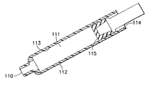
本発明の典型的な実施形態は、図6−14と図28〜図30に示される。カートリッジ112は、図7、図13、および図28〜図30に示される。容積111は、第1の端部110と第2の端部114の間で画定され、薬剤を受け入れるように構成される。隔壁16(図2)はカートリッジ112の第1の端部110に配置され、ストッパー115はカートリッジの第2の端部114の基端に配置され、それにより、容積111をシールする。カートリッジ112は内側表面113を有する。
Exemplary embodiments of the present invention are shown in FIGS. 6-14 and FIGS. 28-30. The
図7、図10、図13、および図28〜図30に示すように、ドライブメンバー121は第1の端部126および第2の端部128を有する。図7と図13に示すように、ドライブメンバー121の第1の端部126がカートリッジ112内に配置され、第2の端部128はカートリッジの外側に配置される。ドライブメンバー121は、スピナー123が接続されたドライブスクリュー127を含む。図29に示すように、ドライブスクリュー127は、スピナー123の内部に嵌合するピンを有し、それにより、スピナーが自由に回転することが可能である。
As shown in FIGS. 7, 10, 13, and 28 to 30, the
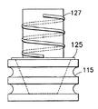
ストッパー115は、図6、図7、図9、図11〜図14、図19および図28〜図31に示すように、実質的に裁頭円錐形状に形成されたキャビティ117を有する。プランジャーまたはドライブメンバー121は、ストッパーキャビティ117と実質的に対応しているフランジ125をもつ、実質的に裁頭円錐形状に形成された嵌合スピナー123を有する。
As shown in FIGS. 6, 7, 9, 11 to 14, 19, and 28 to 31, the
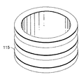
図8と図9に示すように、ストッパー115は第1の端部141および第2の端部143を有する。ストッパーは、図7、図13、図28および図29に示すように、カートリッジ112にスライド可能に(軸線方向に)配置される。ストッパー115の外側表面145はカートリッジ1 12の内側表面113に隣接している。キャビティ117はストッパー115の第1の端部141を通じてアクセスされる。Oリング131(図16)を受け入れるために、ストッパー115の外側表面145には凹部147が形成される。キャビティ117は、図9と図14に示すような、実質的に裁頭円錐形の形状、図15、図17および図18に示すような実質的に円筒形の形状、または、他の適当な形状を有することができる。
As shown in FIGS. 8 and 9, the
図28〜図30は、本発明の典型的な実施形態に係るストッパー115およびドライブメンバー121を含む薬投与200の断面立面図である。投与量ノブ/ボタン224は二重の目的を有し、注入すべき薬の1回の投薬量を設定すること、および、ドライブメンバー121とストッパー115を介して、薬剤カートリッジ112とハブまたはリザーバハウジング(図2)を通して、投与された薬剤を注入することの両方に使用される。薬剤カートリッジ112内のストッパー115の遠位端方向への移動は、薬剤をリザーバハウジング20に押しやる。薬剤カートリッジ12は隔壁16によりシールされ、隔壁16は、リザーバハウジング内に配置された隔壁貫通針カニューレ11によって穿刺される。他のアタッチメント手段も使用可能であるけれども、リザーバハウジング20は、好適には、薬剤カートリッジ112にねじ止めされる。キャップ221は、ユーザーが薬投与ペン200を安全に運ぶことを可能にするために、外側スリーブ213に対してぴったりと嵌合している。
28-30 are cross-sectional elevation views of a
ある量の薬剤が投与されると、ドライブスクリュー127は、図28と図29に示すように、カートリッジ112の第1の端部110に向けて、ストッパー115をカートリッジ112内で軸線方向に動かす。カートリッジ容積111に収容された薬剤が枯渇する、または、カートリッジを処分する必要があると、ドライブスクリュー127は、カートリッジ112の第2の端部114の方向に軸線方向に移動し、これにより、図30に示すように、ストッパーキャビティ117からスピナー123が分離する。スピナー123とストッパー115とが分離されると、カートリッジ112とストッパー115は適切な方法で処分される。
When a certain amount of drug has been administered, the
ストッパー115は、皮内の注射、薄い針ゲージの使用、粘性の液体の注射、または、高速注射から、カートリッジ、注射器、および背圧などの高圧に遭遇する他の均等な投与システムにおける変形を減らす。ストッパー115の形状は、ドライブメンバー121がストッパー115の内側に合致することを可能にし、これにより、テーパーのついた壁により、同時にドライブメンバー121が「自己芯出しする」ことを可能にしながら、ストッパーに支持を与える。カートリッジ112に配置されストッパー115の柔らかいゴムの高さ(厚さ)を減らし、それをドライブメンバー121の堅いプラスチックのスピナー123と置き換えることによって、容積圧縮は、図6に示すように材料を交換せずに削減される。従って、ストッパー115は、長期のインシュリン接触のために確認済みの現在承認されたストッパー材料により形成される。ストッパーの形状は、図5と図6に図解されるように、ストッパーの駆動を「押すこと」からを「引くこと」に変更し、これにより、圧縮された材料の容積を最小化する。
ストッパーの形状は、硬いコア部品として合致スピナー123を利用することにより、ストッパー115の効果的な硬さを増大させる。それゆえに、1つの利点は、図6に示すように高圧の下で容積圧縮が削減されることであり、それにより、投与量精度を増加させ、これはインシュリンまたは他の1回の投薬量が重要な薬剤投与にとって重要である。全体の部品数を維持することによって、良好な経済的利益が提供される。
The shape of the stopper increases the effective hardness of the
スピナー123は、ストッパーキャビティ117と合致される際に、「自己芯だし」機能を提供するために実質的に裁頭円錐形状に形成される。これは、ストッパー115とドライブメンバー121の軸線方向のアラインメントを保証する。スピナー123は自由端部124よりも幅広のベースをドライブスクリュー127の基端側に有し、これにより、ストッパー115からスピナーの取り外しを容易にする。また、フランジ125がスピナー123とドライブスクリュー127との間に設けられ、高圧の下のストッパー変形をさらに減らすために、ストッパー115との接触面積を増加させる。堅い内側スピナー123は、ストッパー115が高圧のもとで崩壊するのを防ぐ。さらに、適切なシールのためのストッパー115表面へのカートリッジ112の接触が維持される。
The
本発明の別の典型的な実施形態においては、ストッパーは、図15、17、および18に示すように、実質的にまっすぐな(すなわち、円筒形状に形成されたキャビティ)キャビティ壁、および、実質的に円筒形状の合致プランジャースピナーを有する。別の典型的な実施形態においては、ドライブメンバー121はフランジを有しない。
In another exemplary embodiment of the present invention, the stopper is substantially straight (ie, a cavity formed in a cylindrical shape) cavity wall and substantially as shown in FIGS. It has a cylindrically shaped mating plunger spinner. In another exemplary embodiment,
図16に示されたさらに別の典型的な実施形態においては、堅いストッパーは、ストッパー115の外側表面145に設けられた、さらにストッパーの効果的な硬さを増加させるための半剛体またはフレキシブルなOリング131を有し、これにより、ストッパーの圧縮性を減らす。Oリング131は、ストッパー115のシール性能も強化し、シール機能を損なうことなくストッパーの全体の高さが削減される。ストッパー115の全体の高さを削減することにより、ストッパーの容積圧縮はさらに削減され、これにより、投与量精度が高まる。
In yet another exemplary embodiment shown in FIG. 16, a rigid stopper is provided on the
別の典型的な実施形態においては、より硬い材料のインサート171がキャビティ117のストッパー115の内部に設けられているが、図31に示すように、外側の柔らか材料に囲まれていない。ストッパー115の外側材料は適切なシールのためより柔軟である。インサート171の第2の硬い材料は、ドライブメンバー121のスピナー123と合致する対応表面を有する。この第2の材料は、ほとんど圧縮しない。図17のストッパーは有効な圧縮性を削減し、それゆえに、投与量精度が高まる。
In another exemplary embodiment, a

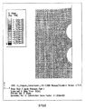
初期の発生圧力はいくつかのアプリケーションにおいて、200psi以上の高さであり、典型的な平衡圧力は約30〜50psiの間にある。表1に示すように、一単位の投与量精度が本発明の典型的な実施形態に係るストッパーで達成される。図3と図4に示すような、既存のストッパーデザインは、表1に示すように、アプリケーション投与量精度要件を満たしていない。さらに、表1は、既存のストッパーと本発明の典型的な実施形態に係るストッパーとの間の改善された投与量精度を示している。 The initial generated pressure is in some applications as high as 200 psi and typical equilibrium pressures are between about 30-50 psi. As shown in Table 1, a unit dosage accuracy is achieved with a stopper according to an exemplary embodiment of the present invention. Existing stopper designs such as those shown in FIGS. 3 and 4 do not meet the application dosage accuracy requirements, as shown in Table 1. In addition, Table 1 shows improved dosage accuracy between existing stoppers and stoppers according to exemplary embodiments of the present invention.
本発明の典型的な実施形態に係るストッパーの有限の要素分析の結果は、図22と図23に示され、既存のストッパーについては図24と図25に示される。図22と図24は、圧力の印加前のストッパー、図23と図25は圧力の印加後のストッパーを示す。図23と図25において明確に示されるように、本発明の典型的な実施形態に係るストッパーは、既存のストッパーよりもかなり変形が小さい。 The results of a finite element analysis of a stopper according to an exemplary embodiment of the present invention are shown in FIGS. 22 and 23, and the existing stoppers are shown in FIGS. 24 and 25. FIG. 22 and 24 show the stopper before application of pressure, and FIGS. 23 and 25 show the stopper after application of pressure. As clearly shown in FIGS. 23 and 25, the stopper according to an exemplary embodiment of the present invention is considerably less deformed than existing stoppers.
本発明を説明するために典型的な実施形態が選択された一方で、添付された特許請求の範囲において定義されるように、本発明の範囲を逸脱せずにその範囲内で様々な変形と部分修正がされうることが、当業者により理解される。 While exemplary embodiments have been selected to describe the present invention, various modifications and changes can be made within the scope of the invention without departing from the scope of the invention, as defined in the appended claims. It will be appreciated by those skilled in the art that partial modifications can be made.
Claims (8)
第1の端部および第2の端部を有し、それらの間の容積を画定するカートリッジであって、前記容積が前記薬剤を収容するように適合するカートリッジと、
第1の端部および第2の端部を有するドライブメンバーであって、前記第1の端部が前記カートリッジ内に配置され、前記第2の端部が前記カートリッジの外側に配置されたドライブメンバーと、
前記ドライブメンバーの前記第1の端部に回転可能に接続されたスピナーであって、実質的に裁頭円錐形状であるスピナーと、
前記カートリッジの容積内にスライド可能に配置されたストッパーであって、前記ストッパー内の実質的に裁頭円錐形状に形成されたキャビティが前記スピナーを受け入れるストッパーと、を備え、
前記ドライブメンバーが前記カートリッジから引き込まれた際に前記ストッパーが前記スピナーから離れる、かつ、前記カートリッジの容積内に残留するように、前記スピナーが前記ストッパーに解放可能に接続されている、機器。 A device for administering a drug,
A cartridge having a first end and a second end and defining a volume therebetween, wherein the volume is adapted to receive the medicament;
A drive member having a first end and a second end, wherein the first end is disposed within the cartridge and the second end is disposed outside the cartridge. When,
A spinner rotatably connected to the first end of the drive member, the spinner being substantially frustoconical;
A stopper slidably disposed within the volume of the cartridge, wherein a cavity formed in a substantially frustoconical shape in the stopper receives the spinner,
An instrument wherein the spinner is releasably connected to the stopper such that the stopper leaves the spinner when the drive member is withdrawn from the cartridge and remains within the volume of the cartridge.
Applications Claiming Priority (3)
| Application Number | Priority Date | Filing Date | Title |
|---|---|---|---|
| US8204108P | 2008-07-18 | 2008-07-18 | |
| US61/082,041 | 2008-07-18 | ||
| PCT/US2009/004131 WO2010008574A1 (en) | 2008-07-18 | 2009-07-17 | Cartridge stopper for an intradermal delivery system |
Publications (3)
| Publication Number | Publication Date |
|---|---|
| JP2011528573A JP2011528573A (en) | 2011-11-24 |
| JP2011528573A5 JP2011528573A5 (en) | 2012-08-23 |
| JP6032892B2 true JP6032892B2 (en) | 2016-11-30 |
Family
ID=41550626
Family Applications (1)
| Application Number | Title | Priority Date | Filing Date |
|---|---|---|---|
| JP2011518735A Active JP6032892B2 (en) | 2008-07-18 | 2009-07-17 | Cartridge stopper for intradermal administration system |
Country Status (6)
| Country | Link |
|---|---|
| US (1) | US9345835B2 (en) |
| EP (1) | EP2307078B1 (en) |
| JP (1) | JP6032892B2 (en) |
| CA (1) | CA2730967C (en) |
| ES (1) | ES2791028T3 (en) |
| WO (1) | WO2010008574A1 (en) |
Families Citing this family (6)
| Publication number | Priority date | Publication date | Assignee | Title |
|---|---|---|---|---|
| JP2014528783A (en) * | 2011-09-08 | 2014-10-30 | サノフィ−アベンティス・ドイチュラント・ゲゼルシャフト・ミット・ベシュレンクテル・ハフツング | Fixing means for drug delivery device |
| JP6093157B2 (en) * | 2012-11-27 | 2017-03-08 | 住友ゴム工業株式会社 | Syringe design method |
| US20180236174A1 (en) * | 2017-02-22 | 2018-08-23 | Mark Curtis Archambeault | Nesting Plunger Tip with Seal Bypass for Syringe Dispensing |
| US10245381B2 (en) | 2017-08-21 | 2019-04-02 | Chalbourne Brasington | Two-step auto-injection device |
| US11040144B1 (en) * | 2017-09-13 | 2021-06-22 | Shao Ma | Plunger assembly for a syringe apparatus |
| JP1631211S (en) * | 2017-11-06 | 2019-05-13 |
Family Cites Families (28)
| Publication number | Priority date | Publication date | Assignee | Title |
|---|---|---|---|---|
| CH620126A5 (en) * | 1978-03-10 | 1980-11-14 | Tulcea Sa | |
| US4421508A (en) * | 1981-02-24 | 1983-12-20 | Cohen Edgar C | Vacuum-compression injector |
| DE3576915D1 (en) * | 1984-06-06 | 1990-05-10 | Medrad Inc | ANGIOGRAPHY INJECTOR AND ANGIOGRAHY SYRINGE USED WITH THIS. |
| US4701165A (en) * | 1986-03-26 | 1987-10-20 | Abbott Interfast Corp. | Reusable syringes |
| US4973318A (en) * | 1988-02-10 | 1990-11-27 | D.C.P. Af 1988 A/S | Disposable syringe |
| US4931040A (en) * | 1988-04-13 | 1990-06-05 | Habley Medical Technology | Safety syringe having a combination needle cannula and articulating hub for retracting said cannula into a medication carpule |
| US4931043A (en) * | 1988-08-08 | 1990-06-05 | Sterling Drug Inc. | Ratchet connector for hypodermic syringe pistons |
| US4955870A (en) * | 1988-08-23 | 1990-09-11 | Ridderheim Kristen A | Hypodermic syringe with retractable needle |
| SE464963B (en) * | 1988-12-14 | 1991-07-08 | Gudmar Olovson | SYRINGE |
| US5378240A (en) * | 1989-11-08 | 1995-01-03 | Curie; Napoleon | Syringe with retractable needle mount |
| AU9128891A (en) * | 1990-12-28 | 1992-08-17 | Scientific Systems Inc. | Single use syringe |
| JPH08164205A (en) | 1993-12-30 | 1996-06-25 | Eisai Co Ltd | Prefilled syringe and gasket falling-off preventing jig and sterilization method using the jig |
| US5522804A (en) * | 1994-02-15 | 1996-06-04 | Lynn; Lawrence A. | Aspiration, mixing, and injection syringe |
| US5785682A (en) | 1995-03-22 | 1998-07-28 | Abbott Laboratories | Pre-filled syringe drug delivery system |
| US6004300A (en) * | 1997-08-28 | 1999-12-21 | Butcher; Robert M | Composite hypodermic syringe piston |
| US6312412B1 (en) * | 1998-12-02 | 2001-11-06 | V. C. Saied, M.D. | Apparatus and method for painless intramuscular or subcutaneous injections |
| JP2000342688A (en) * | 1999-06-01 | 2000-12-12 | Material Eng Tech Lab Inc | Syringe |
| ES2258469T3 (en) | 1999-08-05 | 2006-09-01 | Becton Dickinson And Company | MEDICATION ADMINISTRATION PENCIL. |
| DE10006560A1 (en) | 2000-02-15 | 2001-08-23 | Disetronic Licensing Ag | Two-component piston stopper |
| WO2002005876A2 (en) | 2000-07-14 | 2002-01-24 | Novo Nordisk A/S | A liquid medication delivery device and a method of delivering an intended dose |
| DE10127779A1 (en) | 2001-06-01 | 2002-12-12 | Vetter & Co Apotheker | Twist closure for primary packaging of pharmaceuticals, comprising channels between closure parts to allow flow of sterilizing vapor to closure contact surfaces |
| WO2004030730A2 (en) * | 2002-10-01 | 2004-04-15 | Becton, Dickinson And Company | Medication delivery pen |
| US6932794B2 (en) | 2003-04-03 | 2005-08-23 | Becton, Dickinson And Company | Medication delivery pen |
| EP1735032A1 (en) * | 2004-04-08 | 2006-12-27 | Eli Lilly And Company | Pharmaceutical cartridge piston with rigid core |
| MX2007006975A (en) | 2004-12-09 | 2007-08-15 | West Pharm Serv Inc | Breech loaded fixed needle syringe and automatic injection device having the same. |
| US7645264B2 (en) | 2005-04-11 | 2010-01-12 | Becton, Dickinson And Company | Injection device with secondary reservoir |
| DK2051753T3 (en) | 2006-08-18 | 2016-08-29 | Shl Medical Ab | DEVICE FOR THE DELIVERY OF MEDICINALS, INCLUDING A PRESSURE RELEASE MECHANISM |
| US20100167231A1 (en) * | 2006-11-24 | 2010-07-01 | Dubbe John W | Piston and handheld dispenser including a piston |
-
2009
- 2009-07-17 CA CA2730967A patent/CA2730967C/en active Active
- 2009-07-17 WO PCT/US2009/004131 patent/WO2010008574A1/en active Application Filing
- 2009-07-17 US US12/737,453 patent/US9345835B2/en active Active
- 2009-07-17 ES ES09798311T patent/ES2791028T3/en active Active
- 2009-07-17 EP EP09798311.8A patent/EP2307078B1/en active Active
- 2009-07-17 JP JP2011518735A patent/JP6032892B2/en active Active
Also Published As
| Publication number | Publication date |
|---|---|
| JP2011528573A (en) | 2011-11-24 |
| US20110213311A1 (en) | 2011-09-01 |
| CA2730967C (en) | 2017-01-03 |
| US9345835B2 (en) | 2016-05-24 |
| EP2307078A4 (en) | 2015-08-12 |
| EP2307078B1 (en) | 2020-03-04 |
| CA2730967A1 (en) | 2010-01-21 |
| ES2791028T3 (en) | 2020-10-30 |
| EP2307078A1 (en) | 2011-04-13 |
| WO2010008574A1 (en) | 2010-01-21 |
Similar Documents
| Publication | Publication Date | Title |
|---|---|---|
| EP1896099B1 (en) | Injection device with secondary reservoir | |
| US10653830B2 (en) | Injection mechanism utilizing a vial | |
| JP5203931B2 (en) | Syringe device with forced lockout mechanism and injection rate limiting mechanism | |
| US20080097312A1 (en) | Autoinjector with needle depth adapter | |
| JP6032892B2 (en) | Cartridge stopper for intradermal administration system | |
| BR0212496B1 (en) | PEN TYPE DEVICE BASED ON A MICRO NEEDLE FOR DISTRIBUTION OF MEDICINAL PRODUCTS AND METHOD OF USE | |
| EP2428239A1 (en) | Hub assembly having a hidden needle for a drug delivery pen | |
| JP5662337B2 (en) | Open and close valve drug delivery system for high pressure injection | |
| JP2023021444A (en) | Syringe plunger stopper for high dose accuracy drug delivery |
Legal Events
| Date | Code | Title | Description |
|---|---|---|---|
| A521 | Request for written amendment filed |
Free format text: JAPANESE INTERMEDIATE CODE: A523 Effective date: 20120706 |
|
| A621 | Written request for application examination |
Free format text: JAPANESE INTERMEDIATE CODE: A621 Effective date: 20120706 |
|
| A977 | Report on retrieval |
Free format text: JAPANESE INTERMEDIATE CODE: A971007 Effective date: 20130724 |
|
| A131 | Notification of reasons for refusal |
Free format text: JAPANESE INTERMEDIATE CODE: A131 Effective date: 20130730 |
|
| A521 | Request for written amendment filed |
Free format text: JAPANESE INTERMEDIATE CODE: A523 Effective date: 20131029 |
|
| A02 | Decision of refusal |
Free format text: JAPANESE INTERMEDIATE CODE: A02 Effective date: 20140401 |
|
| A521 | Request for written amendment filed |
Free format text: JAPANESE INTERMEDIATE CODE: A523 Effective date: 20140724 |
|
| RD13 | Notification of appointment of power of sub attorney |
Free format text: JAPANESE INTERMEDIATE CODE: A7433 Effective date: 20140725 |
|
| A521 | Request for written amendment filed |
Free format text: JAPANESE INTERMEDIATE CODE: A821 Effective date: 20140725 |
|
| A911 | Transfer to examiner for re-examination before appeal (zenchi) |
Free format text: JAPANESE INTERMEDIATE CODE: A911 Effective date: 20140814 |
|
| A521 | Request for written amendment filed |
Free format text: JAPANESE INTERMEDIATE CODE: A523 Effective date: 20160302 |
|
| A521 | Request for written amendment filed |
Free format text: JAPANESE INTERMEDIATE CODE: A523 Effective date: 20160726 |
|
| A61 | First payment of annual fees (during grant procedure) |
Free format text: JAPANESE INTERMEDIATE CODE: A61 Effective date: 20161025 |
|
| R150 | Certificate of patent or registration of utility model |
Ref document number: 6032892 Country of ref document: JP Free format text: JAPANESE INTERMEDIATE CODE: R150 |
|
| R250 | Receipt of annual fees |
Free format text: JAPANESE INTERMEDIATE CODE: R250 |
|
| R250 | Receipt of annual fees |
Free format text: JAPANESE INTERMEDIATE CODE: R250 |
|
| R250 | Receipt of annual fees |
Free format text: JAPANESE INTERMEDIATE CODE: R250 |
|
| R250 | Receipt of annual fees |
Free format text: JAPANESE INTERMEDIATE CODE: R250 |