JP6032429B2 - Movie print - Google Patents
Movie print Download PDFInfo
- Publication number
- JP6032429B2 JP6032429B2 JP2013056124A JP2013056124A JP6032429B2 JP 6032429 B2 JP6032429 B2 JP 6032429B2 JP 2013056124 A JP2013056124 A JP 2013056124A JP 2013056124 A JP2013056124 A JP 2013056124A JP 6032429 B2 JP6032429 B2 JP 6032429B2
- Authority
- JP
- Japan
- Prior art keywords
- image
- line
- information
- light
- hue
- Prior art date
- Legal status (The legal status is an assumption and is not a legal conclusion. Google has not performed a legal analysis and makes no representation as to the accuracy of the status listed.)
- Expired - Fee Related
Links
Images


Description
本発明は、偽造防止効果を必要とするセキュリティ印刷物である銀行券、パスポ−ト、有価証券、身分証明書、カ−ド及び通行券等の貴重印刷物の分野において、正反射光下で画像の色彩が大きく変化して、動いているように見える動画模様印刷物に関するものである。 In the field of valuable printed matter such as banknotes, passports, securities, identification cards, cards, and passports, which are security printed matter that requires anti-counterfeiting effects, the present invention The present invention relates to a moving image pattern printed material that appears to move with greatly changing colors.
銀行券、パスポ−ト、有価証券及び身分証明書等に代表されるセキュリティ印刷物には、複製や偽造を防止するために、偽造防止技術が必要とされている。また、偽造防止技術の中でも、すかしやホログラム等に代表される、道具を必要とせず、印刷物を手にしたほとんどの人が真偽判別に利用することができる偽造防止技術が特に必要とされている。 Security printed matter typified by banknotes, passports, securities, identification cards, and the like requires anti-counterfeiting technology in order to prevent duplication and forgery. Also, among anti-counterfeiting technologies, there is a particular need for anti-counterfeiting technologies that can be used for authenticity discrimination by most people who have printed materials, such as watermarks and holograms. ing.
この中でも、画像が動いて見える、いわゆる、「動画的な視覚効果」を備えた偽造防止技術が特に注目されている。画像が動いて見える動画的な視覚効果(以下「動画効果」という。)は、人目を惹きやすく、また、偽造することが困難であることから、近年、セキュリティ印刷物の真偽判別要素として多く用いられる傾向にある。動画効果を実現可能な公知技術としてホログラム、パララックスバリア及びレンチキュラー等を用いた技術が存在し、これらの技術が備える、わずかな角度変化で画像を変化させられるという特徴を活かして、画像が立体的に視認される効果や、動画効果を備えたセキュリティ印刷物は、既に広く存在している。 Among these, anti-counterfeiting technology having a so-called “moving visual effect” in which an image appears to move is particularly attracting attention. In recent years, the visual effects of moving images that appear to move (hereinafter referred to as “moving image effects”) are often attracted to people's eyes and difficult to counterfeit. Tend to be. There are technologies that use holograms, parallax barriers, lenticulars, etc. as well-known technologies that can realize the moving image effect. These technologies provide the ability to change an image with a slight angle change, making the image stereoscopic. There are already widespread security prints with visual effects and animation effects.
しかし、一般的なパララックスバリアやレンチキュラーを用いて動画効果を実現した場合、クリア層かレンズが必要となることから、基材がほぼプラスティックに限定される上、印刷物として再現する場合には、一定の厚み(少なくとも150μm程度)が必要となり、一般に流通する印刷物に許される厚さを超えるため、厚さに制限のある印刷物には用いることができず、一定の厚みが許されるプラスティック製カード以外には採用されない傾向にある。また、ホログラムは、極めて薄く仕上げることが可能であり、銀行券を代表とする各種セキュリティ印刷物に用いられているものの、一般的な印刷物と比較すると、製造工程の複雑さと高い製造コストに大きな問題がある。 However, when a moving image effect is realized using a general parallax barrier or lenticular, a clear layer or lens is required, so the base material is almost limited to plastic, and when reproducing as a printed matter, Other than plastic cards that require a certain thickness (at least about 150 μm) and cannot be used for printed materials with a limited thickness because they exceed the thickness allowed for generally distributed printed materials. Tend not to be adopted. In addition, holograms can be finished very thin and are used in various security prints such as banknotes. However, compared to general prints, there are major problems with the complexity of the manufacturing process and high manufacturing costs. is there.
以上の問題を解決するため、本出願人は、高い光沢及び盛り上がりを有する蒲鉾状の画線に光が入射した場合に、盛り上がりを有する蒲鉾状の画線のうち、入射する光と法線を成す面のみが強く光を反射する現象を利用した、立体効果及び動画効果を形成することが可能な印刷技術を既に出願している(例えば、特許文献1、特許文献2及び特許文献3参照)。特許文献1及び特許文献2に記載の技術は、微小な像や文字等を圧縮して連続して配置した反復性を有する画像を用いて、特定の条件でモアレを生じさせることによって、微小な像や文字等が拡大されて観察される効果を利用したものであり、優れた動画効果を発揮する技術である。また、特許文献3に記載の技術は、特許文献1及び特許文献2に記載の技術のようなモアレ方式とは異なり、インテグラルフォトグラフィと呼ばれる立体画像の撮像方法によって得られる画像を画像処理によって形成したもので、特許文献1及び特許文献2に記載の技術同様に優れた動画効果を実現することができる技術である。これらの技術は、パララックスバリアやレンチキュラーの10分の1程度の厚さで形成することが可能であり、製造技術も従来からある製版技術と印刷技術を活用することで容易に実施可能で、かつ、一般的な印刷物と同じコストで動画効果を備えた印刷画像を形成することができるという優れた特徴を有する。
In order to solve the above problems, the present applicant, when light is incident on a bowl-shaped image line having high gloss and swell, determines the incident light and normal line of the ridge-shaped image line having a bulge. An application has already been filed for a printing technique capable of forming a three-dimensional effect and a moving image effect using a phenomenon in which only the formed surface reflects light strongly (see, for example,
特許文献1から特許文献3までの技術は、いずれも、入射した光を強く正反射する特性を有し、かつ、盛り上がりを有する蒲鉾状の画線や画素の上に、透明な潜像画像を重ね合わせて形成する技術である。透明なインキによって形成された潜像画像は、蒲鉾状の画線や画素に入射する光を遮る働きを成し、潜像画像は、蒲鉾状の画線や画素が光を反射するか否かによって生じた光のコントラストによって可視化される。そのため、潜像画像の色彩は、蒲鉾状の画線や画素から発せられる色彩に制限されるという課題があった。例えば、蒲鉾状の画線や画素が、拡散反射光下では黒色で、正反射時に金色を発する場合、潜像画像は、黒色と金色、更にその中間色の色彩で表現され、例えば、蒲鉾状の画線や画素が、拡散反射光下では青色で、正反射時に赤色を発する場合、潜像画像は、青色と赤色、更にその中間色の色彩で表現される。しかし、蒲鉾状の画線や画素が発することができないその他の色(前者の例では、赤、緑及び青系の色、後者の例では、緑及び黄系の色)は、表現することができなかった。すなわち、いずれの技術も、正反射光下で潜像画像に生じさせ得る色彩は、蒲鉾状の画線中に含まれる機能性顔料の光学特性に依存していた。いかなる最新の機能性材料を用いたとしても、単一のインキによって形成された蒲鉾状の画線だけによって表現することができる色彩変化には自ずから限界があり、より複雑な色彩を表現することは困難であるという問題があった。また、インキ中に配合することができる機能性材料の量には限界があるが、前述のような色彩変化を単一のインキで表現するためは、大量の機能性材料を必要とする場合が多く、インキ設計上、無理のある配合となる場合があった。また、優れた光学特性を有する特殊な機能性材料は、現時点では極めて高価であり、結果として印刷物の価格が高くなるという課題があった。
Each of the techniques from
また、特許文献1から特許文献3までの技術は、いずれも蒲鉾状の画線や画素が正反射するか否かによって生じる反射光の強弱を利用して潜像画像を出現させるため、潜像画像には必ず反射光の弱い領域が存在し、その領域は必然的に暗く沈んだ色彩となる。すなわち、潜像画像全体に彩度の高い色彩を用いることは不可能であった。以上のように、特許文献1から特許文献3までの技術では、正反射光下で出現させられる画像の色彩には大きな制限があるという課題が残されていた。
In addition, since all of the techniques from
また、仮に、特許文献1から特許文献3までの技術において、透明なインキで形成された潜像画像を、正反射光下で視認される程度の濃度を有した色で着色した場合、潜像画像は拡散反射光下でもそのまま視認されてしまい、これらの技術の潜像画像は一見すると暗号のような要素の配列によって形成されるため、鑑賞に耐えない不明瞭な画像となるという課題があった。また、同時に、潜像画像の画線構成が容易に視認されてしまうため、偽造者に画線を容易に読み取られたり、コピーされて同じ効果を偽造品で再現されてしまうおそれがあった。
Further, in the techniques of
本発明は、前述した課題の解決を目的とするものであり、正反射光下で出現する画像の色彩設計の自由度を向上させるとともに、拡散反射光下で出現する画像を、基画像に近い画像として認識することができる、安価で効率的な生産性と偽造防止効果に優れた動画模様印刷物を提案することを目的とする。 The present invention aims to solve the above-described problems, and improves the degree of freedom in color design of an image that appears under specular reflection light, and an image that appears under diffuse reflection light is close to a base image. An object of the present invention is to propose an animated pattern printed matter that can be recognized as an image and is excellent in inexpensive and efficient productivity and anti-counterfeiting effect.
本発明における動画模様印刷物は、基材上の少なくとも一部に、第一の画像、第二の画像及び第三の画像が、基材に向かって順に積層されて成る動画模様を有する動画模様印刷物であって、第一の画像は、基画像を基にして分割されたフレーム内画像を横方向又は縦方向に特定の縮率で圧縮して形成され、それぞれ形状が異なり、かつ、第一の色相を有する情報画線が、第一のピッチで第一の方向に重なり合うことなく複数配置された情報画線群から成り、第二の画像は、正反射光下で第二の色相を発する明暗フリップフロップ性又はカラーフリップフロップ性の少なくともどちらか一方を備えた透明又は半透明の盛り上がりのある蒲鉾状画線を第一のピッチで第一の方向に複数配置した蒲鉾状画線群から成り、第三の画像は、基材と異なる第三の色相を有した有色画線を第一のピッチで第一の方向に複数配置した有色画線群から成り、情報画線の一部は、有色画線同士の間に配置され、情報画線と蒲鉾状画線は、少なくとも一部が重なり合って形成され、基材を正反射光下で角度を変えながら観察することにより、基画像が動いて見えることを特徴とする。 The moving image pattern printed material according to the present invention has a moving image pattern having a moving image pattern in which the first image, the second image, and the third image are sequentially laminated toward the substrate on at least a part of the substrate. The first image is formed by compressing an in-frame image divided based on the base image in a horizontal direction or a vertical direction at a specific reduction ratio, and each has a different shape, and the first image The information image line having a hue is composed of a plurality of information image line groups arranged at the first pitch without overlapping in the first direction, and the second image is a light and dark that emits the second hue under specular reflection light. It is composed of a group of cage-like image lines in which a plurality of transparent or translucent ridge-like image lines having at least one of flip-flop property and color flip-flop property are arranged in a first direction at a first pitch, The third image is different from the substrate It consists of a group of colored image lines in which a plurality of colored image lines having three hues are arranged in the first direction at a first pitch, and a part of the information image lines is arranged between the colored image lines. The line and the saddle-shaped image line are formed so that at least a part thereof is overlapped, and the base image appears to move by observing the substrate while changing the angle under specular reflection light.
本発明における動画模様印刷物は、基材上の少なくとも一部に、第一の画像及び第二の画像が、基材に向かって順に積層されて成る動画模様を有する動画模様印刷物であって、第一の画像は、基画像を基にして分割されたフレーム内画像を横方向又は縦方向に特定の縮率で圧縮して形成され、それぞれ形状が異なり、かつ、第一の色相を有する情報画線が、第一のピッチで第一の方向に重なり合うことなく複数配置された情報画線群から成り、第二の画像は、正反射光下で第二の色相を発する明暗フリップフロップ性又はカラーフリップフロップ性の少なくともどちらか一方を有し、拡散反射光下で基材と異なる第三の色相を備えた盛り上がりのある蒲鉾状画線を第一のピッチで第一の方向に複数配置した蒲鉾状画線群から成り、情報画線の一部は、蒲鉾状画線同士の間に配置され、かつ、情報画線と蒲鉾状画線は、少なくとも一部が重なり合って形成され、基材を正反射光下で角度を変えながら観察することにより、基画像が動いて見えることを特徴とする。 The animated pattern printed matter in the present invention is an animated pattern printed matter having an animated pattern in which a first image and a second image are sequentially laminated toward a substrate on at least a part of the substrate. One image is formed by compressing an in-frame image divided based on a base image in a horizontal or vertical direction at a specific reduction ratio, and has a different shape and a first hue. The second image is composed of a plurality of information image lines arranged at the first pitch without overlapping in the first direction, and the second image is a light / dark flip-flop or color that emits a second hue under specular reflection light. A plurality of raised ridge-like image lines having a third hue different from the base material under diffuse reflected light and having at least one of flip-flop properties are arranged in a first direction at a first pitch. Group of information lines, The part is arranged between the saddle-shaped image lines, and the information image line and the saddle-shaped image line are formed so that at least a part thereof overlaps, and the base material is observed while changing the angle under specular reflection light. Thus, the base image appears to move.
本発明における動画模様印刷物は、有色画線の反射濃度が、情報画線の反射濃度の少なくとも2倍以上であることを特徴とする。 The moving image pattern printed matter according to the present invention is characterized in that the reflection density of the colored image line is at least twice the reflection density of the information image line.
本発明における動画模様印刷物は、拡散反射光下における蒲鉾状画線の反射濃度が、情報画線の反射濃度の少なくとも2倍以上であることを特徴とする The moving image pattern printed matter according to the present invention is characterized in that the reflection density of the saddle-shaped image line under diffuse reflected light is at least twice the reflection density of the information image line.
本発明における動画模様印刷物は、第三の色相を有する画線の幅が、第一のピッチの2/3以上であることを特徴とする請求項1乃至4のいずれか1項に記載の動画模様印刷物。
5. The moving image according to
本発明の動画模様印刷物は、情報画線群(従来技術の潜像画像にあたる画像)を拡散反射光下及び正反射光下においても視認される濃さに着色して形成する。このため、正反射光下で出現する画像の色彩は、従来技術のように蒲鉾状の画線や画素の光学特性のみに依存するものではなく、情報画線群自体の色彩と蒲鉾状画線の正反射時の色彩のそれぞれ別々のインキによる色彩で表現されるため、従来技術のように蒲鉾状の画線や画素のみで複雑な光学特性を実現する必要がなく、無理のないインキ設計が可能である。また、情報画線群を彩度の高い色彩で着色するだけで、正反射光下で出現する画像の彩度を高めることができるため、従来技術のように彩度の制限もない。以上のように、正反射光下で出現する画像の色彩設計の自由度が格段に向上した。加えて、拡散反射光下においては、有色画線群又は蒲鉾状画線群の着色された画線と干渉することで、情報画線群の一部だけをサンプリングした基画像に近い情報画像が可視化され、情報画線群自体は容易に視認されず、読み取りが困難であることから、偽造も困難である。また、拡散反射光下で出現する情報画像は、情報画線群自体のように鑑賞に耐えない不明瞭な画像ではなく、基画像に近い画像となるため、一定の鮮明さを有した有意情報として観察者に認識させるができる。 The moving image pattern printed matter of the present invention is formed by coloring an information image line group (an image corresponding to a latent image of the prior art) to a density that is visible even under diffuse reflected light and regular reflected light. For this reason, the color of an image that appears under specularly reflected light does not depend only on the saddle-shaped image line and the optical characteristics of the pixels as in the prior art, but the color of the information image line group itself and the saddle-shaped image line. Because the colors of each specular reflection are expressed with different ink colors, it is not necessary to realize complex optical characteristics with only a saddle-shaped image line or pixels as in the prior art, and a reasonable ink design Is possible. In addition, since the saturation of an image that appears under specular reflection light can be increased only by coloring the information image line group with a highly saturated color, there is no restriction on saturation as in the prior art. As described above, the degree of freedom in color design of an image that appears under specular reflection light has been greatly improved. In addition, under diffuse reflection, an information image close to the base image obtained by sampling only a part of the information image line group by interfering with the colored image line group or the colored image line of the saddle-shaped image line group. Since it is visualized and the information line group itself is not easily seen and difficult to read, it is difficult to forge. In addition, the information image that appears under diffuse reflected light is not an unclear image that cannot be viewed like the information image line group itself, but is an image close to the base image, so that significant information with a certain sharpness is obtained. As an observer.
また、本発明の動画模様印刷物は、ホログラムのように専用の作製装置や機械を必要とせず、一般的な機能性材料と、既存の印刷機を用いることで作製可能であり、また、特に高い刷り合わせ精度も要求しないことから生産が容易であり、コストパフォーマンスが高い。 Moreover, the moving image pattern printed matter of the present invention does not require a dedicated production device or machine like a hologram, and can be produced by using a general functional material and an existing printing machine, and is particularly high. Since printing accuracy is not required, production is easy and cost performance is high.
さらに、本発明の動画模様印刷物は、動画効果だけでなく、これらに鮮やかな色彩変化を付与することができる。動画視覚効果に加えて、複雑な色彩を再現することはより困難であることから、従来技術よりも偽造防止効果に優れる。 Furthermore, the moving image pattern printed matter of the present invention can give not only the moving image effect but also a vivid color change thereto. In addition to the moving image visual effect, it is more difficult to reproduce a complex color, so that the anti-counterfeiting effect is superior to the prior art.
(第一の実施の形態)
本発明を実施するための形態について、図面を参照して説明する。しかしながら、本発明は、以下に述べる実施するための形態に限定されるものではなく、特許請求の範囲記載における技術的思想の範囲内であれば、その他のいろいろな実施の形態が含まれる。
(First embodiment)
DESCRIPTION OF EMBODIMENTS Embodiments for carrying out the present invention will be described with reference to the drawings. However, the present invention is not limited to the embodiments described below, and includes various other embodiments within the scope of the technical idea described in the scope of claims.
第一の実施の形態では、情報画線群にインテグラルフォトグラフィ方式の画線構成を用いた場合の構成について説明する。インテグラルフォトグラフィとは、特殊な立体画像の撮像方法であり、これによって作られた画像は、動画効果や立体効果に優れるという特徴を有する。 In the first embodiment, a configuration in the case of using an integral photography image line configuration for the information image line group will be described. Integral photography is a special method for capturing a stereoscopic image, and an image created by this method has a feature of being excellent in a moving image effect and a stereoscopic effect.
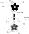
図1に、本発明における動画模様印刷物(1)を示す。図1(a)は、動画模様印刷物(1)の正面図であり、図1(b)に示すのは、動画模様印刷物(1)のAA´ラインにおける断面図である。動画模様印刷物(1)は、基材(2)の上に、動画模様(3)が形成されて成る。基材(2)は動画模様(3)を形成することができれば、紙、プラスティック及び金属等を用いることができ、その材質は問わない。動画模様(3)は、基材(2)と異なる色彩を有している必要があるが、基材(2)と異なる色で、かつ、透明以外の色彩であれば何色でも良く、色彩の制約はない。また、基材(2)の大きさについても、特に制限はない。 In FIG. 1, the moving image pattern printed matter (1) in this invention is shown. Fig.1 (a) is a front view of moving image pattern printed matter (1), and FIG.1 (b) is sectional drawing in the AA 'line of moving image pattern printed matter (1). The animated pattern printed matter (1) is formed by forming an animated pattern (3) on a substrate (2). The substrate (2) can be made of paper, plastic, metal or the like as long as the moving image pattern (3) can be formed. The moving image pattern (3) needs to have a color different from that of the base material (2), but may be any color as long as the color is different from that of the base material (2) and the color is not transparent. There are no restrictions. Moreover, there is no restriction | limiting in particular also about the magnitude | size of a base material (2).
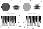
本発明の動画模様(3)の構成の概要を図2に示す。動画模様(3)は、第三の画像(4)、第二の画像(5)及び第一の画像(6)が重ね合わさって成る。図3に第三の画像(4)、第二の画像(5)及び第一の画像(6)の積層順序を示す。第三の画像(4)の上に第二の画像(5)が重なり、第二の画像(5)の上に第一の画像(6)が重なる層構造となっている。 An outline of the structure of the moving image pattern (3) of the present invention is shown in FIG. The moving image pattern (3) is formed by superimposing the third image (4), the second image (5), and the first image (6). FIG. 3 shows the stacking order of the third image (4), the second image (5), and the first image (6). The second image (5) is superimposed on the third image (4), and the first image (6) is superimposed on the second image (5).
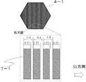
まず、第三の画像(4)について具体的に説明する。図4に示す第三の画像(4)は、有色画線(7)が規則的に複数配置されることで形成された有色画線群を備えて成る。なお、図中において有色画線(7)を横縞の線が複数配列されているように示されているが、これは他の線と区別するためのパターンであり、実際には単純な一本の線である(以下、他の画線も同様とする。)本明細書における規則的に配置されるとは、同じ画線幅、同じピッチ及び同じ方向に配置されることを指す。すなわち、第三の画像(4)は、特定の画線幅(W1)の有色画線(7)が特定のピッチ(P1)で第一の方向(図中S1方向)に連続して複数配置されることで形成された有色画線群を備えて成る。拡散反射光下において、有色画線(7)は、基材(2)と異なる色で、かつ、透明でない第三の色相を有する。第三の画像(4)の中には、有色画線以外の画像も構成し得るが、第一の実施の形態において、第三の画像(4)の中には、有色画線群のみが存在するため、本例においては、第三の画像(4)と有色画線群は同じである。 First, the third image (4) will be specifically described. The third image (4) shown in FIG. 4 includes a group of colored image lines formed by regularly arranging a plurality of colored image lines (7). In the figure, the colored image line (7) is shown as a plurality of horizontal stripes arranged, but this is a pattern for distinguishing from other lines, and in fact it is a simple one. (Hereinafter, the same applies to other drawing lines) means that they are arranged regularly in the present specification in the same drawing line width, the same pitch, and the same direction. That is, in the third image (4), a plurality of colored image lines (7) having a specific image line width (W1) are continuously arranged in a first direction (S1 direction in the figure) at a specific pitch (P1). It is provided with a group of colored lines formed as a result. Under diffusely reflected light, the colored image line (7) has a third hue that is different from the base material (2) and is not transparent. In the third image (4), an image other than a colored image line may be formed. However, in the first embodiment, only the colored image line group is included in the third image (4). Therefore, in this example, the third image (4) and the colored image line group are the same.
次に、第二の画像(5)について具体的に説明する。図5に示す第二の画像(5)は、盛り上がりを有する蒲鉾形状の蒲鉾状画線(8)が規則的に複数配置されることで形成された蒲鉾状画線群を有する。すなわち、特定の画線幅(W2)の蒲鉾状画線(8)が、特定のピッチ(P1)で第一の方向(図中S1方向)に連続して複数配置されることで形成された蒲鉾状画線群を有する。また、蒲鉾状画線(8)は、拡散反射光下において透明又は半透明であって、明暗フリップフロップ性及び/又はカラーフリップフロップ性を有し、正反射光下で第三の色相と異なる第二の色相の反射光を発する。第二の画像(5)の中には、蒲鉾状画線群以外の画像も構成し得るが、第一の実施の形態において、第二の画像(5)の中には蒲鉾状画線群のみが存在するため、本例においては第二の画像(5)と蒲鉾状画線群は同じである。なお、本発明でいう蒲鉾状画線(8)の形状は、蒲鉾形立体のみならず、半円形状又は半楕円形状等の半円立方体の形状も含まれる。 Next, the second image (5) will be specifically described. The second image (5) shown in FIG. 5 has a saddle-like image line group formed by regularly arranging a plurality of saddle-shaped saddle-like image lines (8) having a bulge. That is, it is formed by arranging a plurality of bowl-shaped image lines (8) having a specific image line width (W2) continuously in the first direction (S1 direction in the figure) at a specific pitch (P1). Has a saddle-shaped line group. The saddle-shaped image line (8) is transparent or translucent under diffuse reflected light, has light / dark flip-flop properties and / or color flip-flop properties, and is different from the third hue under regular reflected light. The reflected light of the second hue is emitted. In the second image (5), an image other than the saddle-shaped line group may be formed. In the first embodiment, the second image (5) includes the saddle-shaped line group. In this example, the second image (5) and the saddle-shaped line group are the same. The shape of the saddle-shaped image line (8) in the present invention includes not only a saddle-shaped solid but also a semicircular cubic shape such as a semicircular shape or a semi-elliptical shape.
本発明における「明暗フリップフロップ性」とは、物質に光が入射した場合に、物質の明度が変化する性質を指し、「カラーフリップフロップ性」とは、物質に光が入射した場合に、物質の色相が変わる性質を指す。明暗フリップフロップ性を備えた、印刷で用いるインキとしては、金色や銀色等のメタリック系の金属インキや、グロスタイプの着色インキがある。一般的に艶があると感じられる物質は、明暗フリップフロップ性を備える。例えば、銀インキは、光を強く反射しない拡散反射光下では、暗い灰色にしか見えないが、光を強く反射する正反射光下では、より淡い灰色又は白色に見える。このように、「明暗フリップフロップ性」を有するインキは、正反射光下で明度が変化する。 In the present invention, “light / dark flip-flop” refers to the property that the brightness of a substance changes when light enters the substance, and “color flip-flop” refers to a substance that changes when the light enters the substance. Refers to the property of changing the hue of. Examples of inks used in printing having light and dark flip-flop properties include metallic metallic inks such as gold and silver, and glossy colored inks. Substances that are generally felt glossy have light and dark flip-flop properties. For example, silver ink looks only dark gray under diffusely reflected light that does not reflect light strongly, but appears lighter gray or white under specularly reflected light that strongly reflects light. In this way, the brightness of the ink having “brightness / darkness flip-flop” changes under regular reflection light.
一方のカラーフリップフロップ性を備えた印刷で用いるインキとしては、パールインキや液晶インキ、OVI、CSI(Color Shifting Ink)等が存在する。多くのインキは物体色を有するが、虹彩色パールインキは無色透明である。例えば、赤色の虹彩色パールインキは、拡散反射光下では無色透明だが、正反射光下では赤色の干渉色を発する。このように、「カラーフリップフロップ性」を備えたインキは、正反射光下で色相が変化する。 On the other hand, as ink used in printing having color flip-flop properties, there are pearl ink, liquid crystal ink, OVI, CSI (Color Shifting Ink) and the like. Many inks have an object color, but the iris pearl ink is colorless and transparent. For example, a red iris pearl ink is colorless and transparent under diffuse reflection light, but emits a red interference color under regular reflection light. As described above, the ink having the “color flip-flop property” changes in hue under specular reflection light.
続いて、第一の画像(6)について具体的に説明する。図6に示す第一の画像(6)は、情報画線(9)が規則的に複数配置されることで形成された情報画線群を有する。すなわち、画線幅(W3)の情報画線(9)が、特定のピッチ(P1)で第一の方向(図中S1方向)に連続して複数配置されることで形成された情報画線群を備えて成る。拡散反射光下において、情報画線(9)は、第一の色相を有する。第一の画像(6)の中には、情報画線群以外の画像も構成し得るが、第一の実施の形態において、第一の画像(6)の中には情報画線群のみが存在するため、本例において第一の画像(6)と情報画線群は同じである。 Next, the first image (6) will be specifically described. The first image (6) shown in FIG. 6 has an information image line group formed by regularly arranging a plurality of information image lines (9). In other words, an information image line formed by continuously arranging a plurality of information image lines (9) having an image line width (W3) at a specific pitch (P1) in the first direction (direction S1 in the figure). Comprising a group. Under diffusely reflected light, the information image line (9) has a first hue. In the first image (6), an image other than the information line group may be formed. However, in the first embodiment, only the information line group is included in the first image (6). Therefore, in this example, the first image (6) and the information image line group are the same.
第一の実施の形態における情報画線(9)とは、図7の拡大図に示すように、動画模様として出現させようと意図する画像を基画像(10)(本例では、桜の花びら)とし、基画像(10)の特定の位置に対して決められた特定の大きさのフレームを当てはめて、フレーム内に収まった基画像(10)だけを取り出し、取り出した画像を第一の方向(図中S1方向)に特定の縮率で圧縮して形成したものである。例えば、ある情報画線(9i)の、基画像(10)に対して配置したフレーム(11i)の位置は、隣合う情報画線(9i-1)が基画像(10)に対して配置したフレーム(11i-1)の位置とピッチ(P1)分だけS1方向にずれており、結果として、取り出した基画像(10)は、ピッチ(P1)分だけS1方向にずれた画像となる。以上の手法で作製した情報画線(9i)が、隣り合う情報画線(9i-1)からピッチ(P1)分だけS1方向にのみずらして配置されて成る。すなわち、ピッチ(P1)で隣りあった情報画線同士では、基画像(10)をとり出した画像がピッチ(P1)分だけずれて成り、隣り合った情報画線(9)であってもそれぞれの形状はわずかずつ異なる。この情報画線(9)の具体的な構造と作製方法については、特開2011−126028号公報に基づく。本構成を用いて形成した情報画線群(6)は、正反射光下の動画効果に優れるという特徴を有する。なお、図7に示す情報画線群(6d)は、説明のために本来の情報画線群(6d)の特定の画線幅(W3)や特定のピッチ(P1)を大きくして構造の特徴を容易に把握しやすくデフォルメしたものであり、実際の情報画線群(6)の画像とは異なる。 As shown in the enlarged view of FIG. 7, the information image line (9) in the first embodiment is an image intended to appear as a moving image pattern (10) (in this example, cherry blossom petals). And a frame of a specific size determined for a specific position of the base image (10) is applied, and only the base image (10) within the frame is taken out. It is formed by compressing at a specific reduction ratio in the S1 direction in the figure. For example, the position of the frame (11i) arranged with respect to the base image (10) of a certain information line (9i) is the position of the adjacent information line (9i-1) with respect to the base image (10). The position of the frame (11i-1) and the pitch (P1) are shifted in the S1 direction. As a result, the extracted base image (10) is an image shifted in the S1 direction by the pitch (P1). The information image line (9i) produced by the above method is arranged so as to be shifted only in the S1 direction from the adjacent information image line (9i-1) by the pitch (P1). That is, between the information lines adjacent at the pitch (P1), the image obtained by extracting the base image (10) is shifted by the pitch (P1), and even if the information lines (9) are adjacent to each other. Each shape is slightly different. The specific structure and production method of the information image line (9) is based on Japanese Patent Application Laid-Open No. 2011-126028. The information image line group (6) formed by using this configuration has a feature that the moving image effect under specular reflection light is excellent. The information line group (6d) shown in FIG. 7 has a structure in which the specific line width (W3) and the specific pitch (P1) of the original information line group (6d) are increased for the sake of explanation. The feature is easily grasped and deformed, and is different from the image of the actual information line group (6).
以上の構成の第三の画像(4)、第二の画像(5)及び第一の画像(6)を図3に示す順序で重ね合わせる。このとき、必要となる三つの画像の重ね合わせの位置関係について説明する。まず、基材(2)に最初に形成される第三の画像(4)と第二の画像(5)の重ね合わせに関しては、特に制約はない。第三の画像(4)と第一の画像(6)の重ね合わせに関しては、第三の画像(4)の有色画線(7)と第一の画像(6)の情報画線(9)とが、一部で重なり合わない領域を有する必要がある。言い変えれば、有色画線(7)と有色画線(7)との間の、有色画線(7)のない非画線領域に第一の画像の情報画線(9)の一部が重なっている必要がある。その場合、非画線領域と情報画線(9)の間に第二の画像(5)の蒲鉾状画線(8)があっても良く、なくても良い。この条件が満たされない場合には、拡散反射光下で基画像(10)に近似した情報画像A(10A)が出現しないため、避けなければならない。また、第二の画像(5)と第一の画像(6)の重ね合わせに関しては、第二の画像(5)が備える蒲鉾状画線(8)と第一の画像(6)の情報画線(9)とが、少なくとも一部で重なり合う領域を有する必要がある。この条件が満たされない場合には、正反射光下で基画像(10)に近似した情報画像B(10B)が出現しないため、避けなければならない。以上のような適切な位置関係で三つの画像が積層された場合、以下に説明する効果が生じる。 The third image (4), the second image (5), and the first image (6) having the above configuration are superimposed in the order shown in FIG. At this time, the necessary positional relationship of the superposition of the three images will be described. First, there are no particular restrictions on the overlay of the third image (4) and the second image (5) that are initially formed on the substrate (2). Regarding the superposition of the third image (4) and the first image (6), the colored image line (7) of the third image (4) and the information image line (9) of the first image (6). Need to have areas that do not overlap in part. In other words, a part of the information image line (9) of the first image is located in the non-image area without the color image line (7) between the color image line (7) and the color image line (7). It needs to overlap. In that case, the saddle-like image line (8) of the second image (5) may or may not exist between the non-image area and the information image line (9). If this condition is not satisfied, the information image A (10A) that approximates the base image (10) does not appear under diffuse reflected light and must be avoided. Regarding the superposition of the second image (5) and the first image (6), the information image of the saddle-shaped image line (8) and the first image (6) included in the second image (5). The line (9) needs to have an area at least partially overlapping. If this condition is not satisfied, the information image B (10B) that approximates the base image (10) does not appear under regular reflection light, and must be avoided. When three images are stacked in an appropriate positional relationship as described above, the effects described below occur.
第1の実施の形態における動画模様印刷物(1)の効果について図8を用いて説明する。図8(a)に示すように、本発明の動画模様印刷物(1)を拡散反射光下で観察した場合、基画像(10)に近似した画像である情報画像A(10A)が視認される。拡散反射光下での情報画像A(10A)の色は、第一の色相及び第三の色相で表され、動画模様(3)のその他の領域は第三の色相となる。拡散反射光下では、動画模様(3)中のいかなる画像も動いては見えない。 The effect of the moving image pattern printed matter (1) in the first embodiment will be described with reference to FIG. As shown in FIG. 8A, when the moving image printed matter (1) of the present invention is observed under diffuse reflected light, an information image A (10A) that is an image approximate to the base image (10) is visually recognized. . The color of the information image A (10A) under diffuse reflected light is represented by the first hue and the third hue, and the other areas of the moving image pattern (3) are the third hue. Under diffuse reflection, any image in the moving image pattern (3) cannot be seen.
図8(b)に示すように、本発明の動画模様印刷物(1)を正反射光下で観察した場合、情報画像A(10A)は、不可視か、不可視に近くなるとともに、基画像(10)に近似した画像である情報画像B(10B)が出現する。正反射光下では、情報画像B(10B)は第一の色相で、その他の動画模様(3)の領域は、第二の色相で視認される。拡散反射光下で出現する情報画像A(10A)とは異なり、情報画像B(10B)の色相には第二の色相はほとんど反映されず、第一の色相が主体的となる。なお、情報画像A(10A)と情報画像B(10B)は、いずれも基画像(10)に近似した画像ではあるが、完全に同一の画像というわけではない。この二つの画像(10A及び10B)の具体的な違いについては後述する。図8(c)に示すように、正反射光下で角度を変化させて観察した場合には、情報画像B(10B)の位置がS1方向に平行に移動する。すなわち、動画模様(3)の中を情報画像B(10B)が動いて観察される。 As shown in FIG. 8B, when the moving image pattern printed matter (1) of the present invention is observed under specular reflection light, the information image A (10A) is invisible or close to invisible, and the base image (10 ) Appears, an information image B (10B) that is an image approximated to. Under regular reflection light, the information image B (10B) is visually recognized in the first hue, and the other moving image pattern (3) is visually recognized in the second hue. Unlike the information image A (10A) that appears under diffuse reflected light, the second hue is hardly reflected in the hue of the information image B (10B), and the first hue is dominant. The information image A (10A) and the information image B (10B) are both images similar to the base image (10), but are not completely the same image. A specific difference between the two images (10A and 10B) will be described later. As shown in FIG. 8C, when the observation is performed while changing the angle under regular reflection light, the position of the information image B (10B) moves in parallel to the S1 direction. That is, the information image B (10B) moves and is observed in the moving image pattern (3).
以上の効果が生じる原理について説明する。まず、拡散反射光下において、情報画線群(6)がそのまま視認されるのではなく、基画像(10)に近似した画像である情報画像A(10A)が視認される。拡散反射光下において第二の画像(5)の蒲鉾状画線(8)は、正反射光を発しないため、透明又は半透明であり、完全に不可視か、ほぼ不可視である。一方の第三の画像(4)と第一の画像(6)は、それぞれ着色されて成るため、拡散反射光下では可視化されている。ただし、第三の画像(4)の有色画線(7)と第一の画像(6)の情報画線(9)は、それぞれ同じピッチで配置され、かつ、目視可能な濃度に着色されて成るために拡散反射光下ではこの二つの画線が干渉する。この二つの画線が干渉して生じる現象について、図9(a)を用いて以下に説明する。 The principle that produces the above effect will be described. First, under diffuse reflection, the information image line group (6) is not visually recognized as it is, but the information image A (10A) that is an image approximate to the base image (10) is visually recognized. Under the diffuse reflection light, the saddle-shaped image line (8) of the second image (5) does not emit specular reflection light, and thus is transparent or translucent, and is completely invisible or almost invisible. Since the third image (4) and the first image (6) are colored, they are visualized under diffuse reflected light. However, the colored image line (7) of the third image (4) and the information image line (9) of the first image (6) are arranged at the same pitch and colored to a visible density. Therefore, these two lines interfere with each other under diffusely reflected light. A phenomenon caused by the interference of these two image lines will be described below with reference to FIG.
図9(a)の下の図は、有色画線(7)と情報画線(9)が重なった構造を示す図である。情報画線(9)は、有色画線(7)と比較して淡い反射濃度で形成されるために、有色画線(7)の上に情報画線(9)が重なった領域(9A)の濃度は、印刷面積の増加が伴わない減法混色となり、もとの有色画線(7)の反射濃度から大きく変化しない。その一方、有色画線(7)と隣り合う有色画線(7)の間に存在する非画線部に情報画線(9)が重なった領域(9B)は、着色された印刷面積自体が増加するため、その領域(9B)の反射濃度は、情報画線(9)の反射濃度分がそのまま増加した反射濃度となり、相対的に反射濃度が大きく増加する。有色画線(7)の上に情報画線(9)が重なった領域(9A)は、反射濃度の増加が相対的に低く、非画線部の上に情報画線(9)が重なった領域(9B)は、反射濃度の増加が相対的に高くなるため、情報画線(9)の一部が、有色画線(7)の有無によってサンプリングされ、反射濃度の高低として現れる。有色画線(7)は、特定のピッチ(P1)の周期をもって第一の方向に配置されて成ることから、サンプリングされて現れる画像は、情報画線群(6)をピッチ(P1)の周期で第一の方向に周期的にサンプリングした画像となる。情報画線群(6)は、基画像(10)を第一の方向に特定の縮率で圧縮した情報画線(9)をピッチ(P1)で規則的に配置して構成した画像であるから、特定の幅(有色画線(7)と有色画線(7)間の非画線部の幅がこれにあたる)によってピッチ(P1)でサンプリングした場合には、基画像(10)に近似した画像が出現する。以上の原理によって拡散反射光下で出現する基画像(10)に近似した画像を、本明細書では情報画像A(10A)とする。情報画像A(10A)は、有色画線(7)と有色画線(7)間の非画線部の幅が狭くなればなるほどサンプリングされる領域が限定されるため、基画像(10)により近似した形状として可視化される。 The lower part of FIG. 9A shows a structure in which the colored image line (7) and the information image line (9) overlap. Since the information image line (9) is formed with a lighter reflection density than the colored image line (7), the area (9A) where the information image line (9) overlaps the colored image line (7). The subtractive density is a subtractive color mixture that does not increase the printing area, and does not change significantly from the reflection density of the original colored image line (7). On the other hand, the area (9B) where the information image line (9) overlaps the non-image area existing between the color image line (7) and the adjacent color image line (7) has a colored print area itself. Therefore, the reflection density of the area (9B) becomes a reflection density in which the reflection density of the information image line (9) is increased as it is, and the reflection density is relatively greatly increased. In the area (9A) where the information image line (9) overlaps the colored image line (7), the increase in reflection density is relatively low, and the information image line (9) overlaps the non-image area. In the region (9B), since the increase in reflection density is relatively high, a part of the information image line (9) is sampled depending on the presence or absence of the colored image line (7), and appears as a high or low reflection density. Since the colored image line (7) is arranged in the first direction with a period of a specific pitch (P1), the image that is sampled appears on the information line group (6) with the period of the pitch (P1). Thus, an image periodically sampled in the first direction is obtained. The information image line group (6) is an image configured by regularly arranging information image lines (9) obtained by compressing the base image (10) in the first direction at a specific reduction ratio at a pitch (P1). From this, when sampling at a pitch (P1) with a specific width (the width of the non-image portion between the colored image line (7) and the colored image line (7) corresponds to this), it approximates the base image (10) Appears. An image approximated to the base image (10) appearing under diffuse reflection light based on the above principle is referred to as an information image A (10A) in this specification. In the information image A (10A), the area to be sampled is limited as the width of the non-image line portion between the color image line (7) and the color image line (7) becomes narrower. Visualized as an approximate shape.
また、拡散反射光下において、出現する情報画像A(10A)のうち、情報画線(9)が有色画線(7)と重なり合った領域(9A)は、第三の色相と第一の色相が重なり合うため、二つの色相を減法混色した合成色となり、出現する情報画像A(10A)のうち、情報画線(9)と有色画線(7)が重ならなかった領域(9B)は、第一の色相となる。動画模様(3)のそれ以外の領域は、第三の色相となる。なお、基材(2)の色が白以外の場合には、それぞれの色相に基材の色相を減法混色した合成色となる。以上のように、拡散反射光下では、着色された二つの画線である、すなわち、有色画線(7)と情報画線(9)が干渉することで、情報画像A(10A)が可視化される。 In addition, in the information image A (10A) that appears under diffuse reflected light, the region (9A) where the information image line (9) overlaps the colored image line (7) has a third hue and a first hue. Therefore, in the appearing information image A (10A), the area (9B) where the information image line (9) and the colored image line (7) do not overlap is obtained. The first hue. The other area of the moving image pattern (3) is the third hue. In addition, when the color of a base material (2) is other than white, it becomes a synthetic color which subtractively mixed the hue of the base material with each hue. As described above, the information image A (10A) is visualized by interference between the two colored lines, that is, the colored line (7) and the information line (9) under diffuse reflected light. Is done.
続いて、正反射光下において、基画像(10)に近似した画像である情報画像B(10B)が視認される原理について説明する。正反射光下において第二の画像(5)の蒲鉾状画線(8)は、明暗フリップフロップ性又はカラーフリップフロップ性を有するために、第二の色相を有する強い正反射光を発する。この強い正反射光によって、第二の画像(5)の下にある第三の画像(4)の中の細かな画線の有無や色相は、判別することができなくなる。このため、拡散反射光下で生じていた有色画線(7)と情報画線(9)が干渉する現象は失われる。正反射光下では、第二の色相を発する蒲鉾状画線(8)と、蒲鉾状画線(8)の画線表面に重ねられた第一の色相の情報画線(9)とが干渉する。この二つの画線が干渉して生じる現象について、図9(b)を用いて以下に説明する。 Subsequently, the principle of visually recognizing the information image B (10B) that is an image approximate to the base image (10) under regular reflection light will be described. Under specular reflection light, the saddle-shaped image line (8) of the second image (5) emits strong specular reflection light having a second hue because it has a light-dark flip-flop property or a color flip-flop property. Due to this strong specularly reflected light, it is impossible to determine the presence or hue of fine lines in the third image (4) under the second image (5). For this reason, the phenomenon of interference between the colored image line (7) and the information image line (9) generated under diffuse reflected light is lost. Under specular reflection light, the hook-shaped image line (8) emitting the second hue interferes with the information image line (9) of the first hue superimposed on the surface of the hook-shaped image line (8). To do. A phenomenon caused by the interference of these two image lines will be described below with reference to FIG.
図9(b)の下の図は、蒲鉾状画線(8)と情報画線(9)が重なった構造に、光が入射した状況を示す図である。正反射光下では、蒲鉾状画線(8)が第二の色相で可視化し、その下の有色画線(7)が不可視となるため、その画線表面に重ねられた第一の色相を有する情報画線(9)が、色相の違いによってコントラストを得て可視化される。蒲鉾状画線(8)は、その名のとおりに蒲鉾状の盛り上がりを有するために、光が入射したとしても蒲鉾状画線(8)の画線表面全体が正反射して第二の色相で可視化するわけではない。可視化するのは、蒲鉾状画線(8)の画線表面のうちの、入射する光と直交した画線表面の一部の領域(8S)のみであり、この入射光と直交した領域(8S)のみが第二の色相で可視される。蒲鉾状画線(8)は、全て同じ形状であることから、この入射光と直交した領域(8S)は、ピッチ(P1)で配置された、それぞれの蒲鉾状画線(8)の同じ位置に発生するため、結果としてピッチ(P1)の間隔で、第二の色相により光を強く正反射する領域が生まれる。また、蒲鉾状画線(8)の画線表面には情報画線(9)が重ねられており、蒲鉾状画線(8)がピッチ(P1)で光を強く正反射すると、蒲鉾状画線(8)の画線表面に重ねられた情報画線(9)の中でも、入射光と直交した領域(8S)の中に存在した情報画線の一部(9D)は、強く可視化される一方で、入射光と直交した領域(8S)以外に存在した情報画線の一部(9C)は、可視化されない現象が生まれ、結果として情報画線(9)がピッチ(P1)でサンプリングされ、第二の色相と第一の色相の違いによって、基画像(10)に近似した画像が可視化される。正反射光下で出現する基画像(10)に近似した画像を、本明細書では情報画像B(10B)とする。情報画像B(10B)は、蒲鉾状画線(8)の入射光と直交した領域(8S)が狭くなればなるほどサンプリングされる領域が限定されるため、基画像(10)により近似した形状として可視化される。 The lower part of FIG. 9B is a diagram showing a state in which light is incident on the structure in which the bowl-shaped image line (8) and the information image line (9) overlap. Under specular reflection light, the hook-shaped image line (8) is visualized in the second hue, and the colored image line (7) below it is invisible. Therefore, the first hue superimposed on the surface of the image line is displayed. The information line (9) that the user has is visualized by obtaining contrast according to the difference in hue. Since the saddle-like image line (8) has a saddle-like bulge as its name suggests, even when light is incident, the entire surface of the image line of the saddle-like image line (8) is regularly reflected and the second hue. It is not necessarily visualized with. What is visualized is only a partial area (8S) of the surface of the image line perpendicular to the incident light, out of the surface of the image line of the bowl-shaped image line (8), and an area (8S) orthogonal to the incident light. Only visible in the second hue. Since the saddle-shaped image line (8) has the same shape, the region (8S) orthogonal to the incident light has the same position of the respective saddle-shaped image lines (8) arranged at the pitch (P1). As a result, a region in which light is strongly regularly reflected by the second hue is generated at intervals of the pitch (P1). The information image line (9) is superimposed on the surface of the image line of the hook-shaped image line (8), and when the beam-shaped image line (8) strongly reflects the light strongly at the pitch (P1), Among the information lines (9) superimposed on the surface of the line (8), a part (9D) of the information line existing in the region (8S) orthogonal to the incident light is strongly visualized. On the other hand, a part (9C) of the information line existing outside the region (8S) orthogonal to the incident light is not visualized. As a result, the information line (9) is sampled at the pitch (P1), Due to the difference between the second hue and the first hue, an image approximated to the base image (10) is visualized. In this specification, an image approximate to the base image (10) that appears under specular reflection light is referred to as an information image B (10B). In the information image B (10B), the region to be sampled is limited as the region (8S) orthogonal to the incident light of the bowl-shaped image line (8) becomes narrower. Visualized.
正反射光下においては、情報画像B(10B)は、第一の色相で、動画模様(3)のそれ以外の領域は、第二の色相で可視化される。以上のように、正反射光下では、正反射光下でも視認される二つの画線である、すなわち、蒲鉾状画線(8)と情報画線(9)が干渉することで、情報画像B(10B)が可視化される。 Under regular reflection light, the information image B (10B) is visualized in the first hue, and the other area of the moving image pattern (3) is visualized in the second hue. As described above, under specular reflection light, two image lines that are visible even under specular reflection light, that is, the saddle-shaped image line (8) and the information image line (9) interfere with each other, so that the information image B (10B) is visualized.
なお、拡散反射光下で出現した情報画像A(10A)と、正反射光下で出現した情報画像B(10B)とは、情報画線群(6)の一部をサンプリングすることによって出現する画像であり、同じく基画像(10)に近似した画像であるが、厳密には、情報画線群(6)をサンプリングする位置が異なっており、また、サンプリングする幅も異なるために、似ていても完全に同じ画像とはならない。 The information image A (10A) that appears under diffusely reflected light and the information image B (10B) that appears under regular reflected light appear by sampling a part of the information line group (6). It is an image that is also similar to the base image (10). Strictly speaking, the information image line group (6) is sampled at different positions, and the sampling width is also different. However, the images are not exactly the same.
また、出現した情報画像B(10B)が動画模様(3)の中で動いて見える原理について説明する。情報画像B(10B)は、入射する光と直交した画線表面の一部の領域(8S)に重ねられた位置の情報画線(9D)をサンプリングして可視化された画像であることから、光の入射角度が変わったり、入射する光に対する動画模様印刷物(1)の角度が変わることで、入射する光と直交した画線表面の一部の領域(8S)の位置も画線表面上で第一の方向と平行な方向に移動する。仮に、A側の方向に光源が移動したとすると、入射する光と直交した画線表面の一部の領域(8S)もA側に移動し、B側の方向に光源が移動したとすると、入射する光と直交した画線表面の一部の領域(8S)もB側に移動する。蒲鉾状画線(8)の画線表面上に重ねられた情報画線(9)は、第一の方向に基画像(10)を圧縮して形成した画像であるため、それぞれの情報画線(9)の中には、基画像(10)を第一の方向に移動させた画像情報が含まれている。そのため、正反射光下で観察する角度を変えることで、蒲鉾状画線(8)の画線表面の光と直交した領域(8S)の位置が変化し、サンプリングされる情報画線(9)の位置が変化することによって、可視化される情報画像B(10B)の位相が変化し、情報画像B(10B)が動いているように見える。以上の原理によって動画模様(3)の中を情報画像B(10B)が動いているように見える。加えて、これに付随する効果として、右眼で動画模様(3)を見た場合と、左眼で動画模様(3)を見た場合には、観察角度の違いから動画模様(3)中に出現する情報画像B(10B)の第一の方向の位相が異なって観察されるために、両眼視差に起因する立体感が生じる。第一の実施の形態の例では、情報画像B(10B)は、動画模様(3)が実際にある位置よりも手前に存在するように見える。 In addition, the principle that the appearing information image B (10B) appears to move in the moving image pattern (3) will be described. Since the information image B (10B) is an image visualized by sampling the information image line (9D) at a position superimposed on a partial area (8S) of the image surface perpendicular to the incident light, By changing the incident angle of the light or the angle of the moving image printed matter (1) with respect to the incident light, the position of a part of the region (8S) on the surface of the image line orthogonal to the incident light is also on the image surface. Move in a direction parallel to the first direction. If the light source is moved in the A side direction, a part of the surface of the image line (8S) orthogonal to the incident light is also moved to the A side, and the light source is moved in the B side direction. A part of the surface of the image line (8S) orthogonal to the incident light also moves to the B side. The information image line (9) superimposed on the surface of the image line of the saddle-shaped image line (8) is an image formed by compressing the base image (10) in the first direction. (9) includes image information obtained by moving the base image (10) in the first direction. Therefore, by changing the angle of observation under specular reflection light, the position of the region (8S) orthogonal to the light on the surface of the saddle-shaped image line (8) changes, and the information image line (9) to be sampled is sampled. Is changed, the phase of the visualized information image B (10B) is changed, and the information image B (10B) appears to move. The information image B (10B) seems to move in the moving image pattern (3) by the above principle. In addition, as an accompanying effect, when the moving image pattern (3) is viewed with the right eye and when the moving image pattern (3) is viewed with the left eye, the moving image pattern (3) is Since the information image B (10B) that appears in the first image is observed with a different phase in the first direction, a stereoscopic effect due to binocular parallax occurs. In the example of the first embodiment, the information image B (10B) seems to exist before the position where the moving image pattern (3) is actually located.
以上が本発明の動画模様印刷物(1)の効果が生じる原理である。すなわち、拡散反射光下では、第三の画像(4)の有色画線(7)と第一の画像(6)の情報画線(9)とが干渉することで情報画像A(10A)が可視化され、正反射光下では、第二の画像(5)の蒲鉾状画線(8)と、第一の画像(6)の情報画線(9)とが干渉することで情報画像B(10B)が可視化される。また、入射する光の角度が変わることによって蒲鉾状画線(8)の光を強く反射する画線表面が移動し、それに伴って情報画線(9)から情報画像B(10B)の位置が変化した画像がサンプリングされることで情報画像B(10B)が動いて見える。 The above is the principle that produces the effect of the moving image printed matter (1) of the present invention. That is, under diffuse reflected light, the colored image line (7) of the third image (4) interferes with the information image line (9) of the first image (6), so that the information image A (10A) Under visible and specularly reflected light, the saddle-shaped image line (8) of the second image (5) and the information image line (9) of the first image (6) interfere with each other so that the information image B ( 10B) is visualized. Further, the surface of the image line that strongly reflects the light of the saddle-shaped image line (8) is moved by changing the angle of the incident light, and the position of the information image B (10B) from the information image line (9) is accordingly moved. The information image B (10B) appears to move by sampling the changed image.
第一の実施の形態において、正反射光下で出現する情報画像B(10B)が一種類の画像から成る例で説明したが、複数の異なる画像とすることもできる。情報画線群(6)の具体的な構成については、特開2011−126028号公報に記載の様々な構成を用いることができる。 In the first embodiment, the information image B (10B) that appears under specular reflection light has been described as an example of one type of image. However, a plurality of different images may be used. As a specific configuration of the information line group (6), various configurations described in Japanese Patent Application Laid-Open No. 2011-126028 can be used.
なお、本明細書中でいう正反射とは、物質にある入射角度で光が入射した場合に、入射した光の角度と略等しい角度に強い反射光が生じる現象を指し、拡散反射とは、物質にある入射角度で光が入射した場合に、入射した光の角度と異なる角度に弱い反射光が生じる現象を指す。例えば、虹彩色パールインキを例とすると、拡散反射の状態では無色透明に見えるが、正反射した状態では特定の干渉色を発する。正反射光下で観察するとは、印刷物に入射した光の角度と略等しい反射角度に視点をおいて観察する状態を指し、拡散反射光下で観察するとは、印刷物に入射した光の角度と大きく異なる角度で観察する状態を指す。 In addition, specular reflection in this specification refers to a phenomenon in which strong reflected light is generated at an angle substantially equal to the angle of incident light when light is incident on a substance at an incident angle. Diffuse reflection is This refers to a phenomenon in which weak reflected light is generated at an angle different from the angle of incident light when light is incident on a substance at an incident angle. For example, when an iris pearl ink is taken as an example, it appears colorless and transparent in the diffuse reflection state, but emits a specific interference color in the regular reflection state. Observing under specularly reflected light means observing from a viewpoint at a reflection angle that is substantially equal to the angle of light incident on the printed material, and observing under diffusely reflected light means a larger angle than the angle of light incident on the printed material. It refers to the state of observation at different angles.
第一の実施の形態の動画模様印刷物(1)において、第三の画像(4)、第二の画像(5)及び第一の画像(6)のそれぞれの画線の配置ピッチ及び配置方向は、同じである必要がある。すなわち、いずれの画線も全て同じピッチ(P1)で、かつ、全て同じ第一の方向(図中S1方向)に連続して配置される。なお、各画線の幅(W1)、(W2)及び(W3)は同じであっても、異なっていても良いが、いずれもピッチ(P1)の2分の1以上の値である必要がある。特に、有色画線の幅(W1)については、ピッチ(P1)の3分の2以上の値であることが望ましい。これらの値を満たさない場合、拡散反射光下で出現する情報画像A(10A)及び正反射光下で出現する情報画像B(10B)がともに不明瞭な画像となるため、好ましくない。 In the moving image pattern printed matter (1) of the first embodiment, the arrangement pitch and the arrangement direction of the image lines of the third image (4), the second image (5), and the first image (6) are as follows. Need to be the same. That is, all the image lines are continuously arranged at the same pitch (P1) and all in the same first direction (direction S1 in the drawing). Note that the widths (W1), (W2), and (W3) of each image line may be the same or different, but all of them need to be a value equal to or greater than half the pitch (P1). is there. In particular, the width (W1) of the colored image line is desirably a value of two-thirds or more of the pitch (P1). If these values are not satisfied, the information image A (10A) appearing under diffuse reflection light and the information image B (10B) appearing under regular reflection light are both unclear, which is not preferable.
(第二の実施の形態)
また、本発明の動画模様印刷物の動画模様(3´´)は、第三の画像を用いずに構成することもできる。図10は、第二の画像(5´´)と第一の画像(6´´)の二つの画像のみを用いて動画模様(3´´)を形成した例である。この場合、第二の画像(5´´)の蒲鉾状画線(図示せず)は、透明や半透明ではなく、かつ、明暗フリップフロップ性又はカラーフリップフロップ性を有する必要がある。具体的には、拡散反射光下では第三の色相の実体色を有し、正反射光下では第二の色相を発する特性を有する必要がある。 このように第三の画像を用いない構成で本発明の動画模様(3´´)を形成する場合、第二の画像(5´´)と第一の画像(6´´)の重なり合いの位置関係については、蒲鉾状画線と蒲鉾状画線の間の少なくとも情報画線が配された領域を有する必要があり、かつ、蒲鉾状画線と情報画線が少なくとも一部で重なり合って形成される必要がある。
(Second embodiment)
Moreover, the moving image pattern (3 ″) of the moving image pattern printed material of the present invention can be configured without using the third image. FIG. 10 shows an example in which a moving image pattern (3 ″) is formed using only two images, the second image (5 ″) and the first image (6 ″). In this case, the saddle-shaped image line (not shown) of the second image (5 ″) is not transparent or translucent, and needs to have light / dark flip-flop property or color flip-flop property. Specifically, it is necessary to have a characteristic of having a solid color of the third hue under diffuse reflection light and emitting a second hue under regular reflection light. In this way, when the moving image pattern (3 ″) of the present invention is formed without using the third image, the overlapping position of the second image (5 ″) and the first image (6 ″). As for the relationship, it is necessary to have at least a region where the information line is arranged between the hook-shaped line and the hook-shaped line, and the hook-shaped line and the information line are formed to overlap at least partially. It is necessary to
このような二つの画像で形成する場合でも、拡散反射光下では、第二の画像(5´´)の蒲鉾状画線の実体色と、第一の画像(6´´)の情報画線(図示せず)とが干渉することで、情報画像A(図示せず)が可視化され、正反射光下では第二の画像(5´´)の蒲鉾状画線から生じる反射光と、第一の画像(6´)の情報画線とが干渉することで、情報画像B(図示せず)が可視化される。また、入射する光の角度が変わることによって蒲鉾状画線の光を強く反射する画線表面が移動し、それに伴って情報画線から情報画像Bの位置が変化した画像がサンプリングされることで情報画像Bが動いて見える効果が生じ、加えて、両眼視差に基づく遠近感も同時に生じる。このような構成の動画模様印刷物は、作製が容易であって、コストを低く抑えられるという特徴を有する。 Even in the case of forming with these two images, under diffuse reflection light, the solid color of the saddle-shaped image line of the second image (5 ″) and the information image line of the first image (6 ″) Information image A (not shown) is visualized by interference with (not shown), and reflected light generated from the saddle-shaped image line of the second image (5 ″) under the specularly reflected light, The information image B (not shown) is visualized by interference with the information image line of one image (6 ′). In addition, by changing the angle of the incident light, the surface of the image line that strongly reflects the light of the saddle-shaped image line moves, and accordingly, an image in which the position of the information image B is changed from the information image line is sampled. The effect is that the information image B appears to move, and in addition, a perspective based on binocular parallax also occurs. The moving image pattern printed matter having such a configuration is easy to manufacture and has a feature that the cost can be kept low.
以上のように、本発明の動画模様印刷物において用い得る構成は、これまで説明した実施の形態に記載の例に限定されるものではなく、その他様々な構成を用い得る。 As described above, the configuration that can be used in the moving image printed matter of the present invention is not limited to the examples described in the embodiments described above, and various other configurations can be used.
本発明の動画模様印刷物(1)において、第三の色相と第二の色相、第一の色相(二種類以上の情報画線を備える場合には、第四の色相や情報画線に含まれるそれ以外の色相等も第一の色相と同じ条件となる。)については、第二の色相と第一の色相とが補色か、それに近い関係で大きく異なる色相であることが望ましい。第三の色相と第二の色相の関係及び第三の色相と第一の色相の関係については、特に制約はない。ただし、第三の色相と第一の色相が大きく異なる場合、動画効果は低下する傾向にあるため、動画効果を優先する場合には、第三の色相と第一の色相は近い色相とすることが望ましい。 In the moving image pattern printed matter (1) of the present invention, the third hue, the second hue, and the first hue (in the case where two or more kinds of information lines are provided, they are included in the fourth hue and the information line). For the other hues and the like, the same conditions as for the first hue are used.) It is desirable that the second hue and the first hue are complementary colors or have substantially different hues because of their close relationship. There are no particular restrictions on the relationship between the third hue and the second hue and the relationship between the third hue and the first hue. However, if the third hue and the first hue are significantly different, the movie effect tends to decrease. Therefore, when priority is given to the movie effect, the third hue and the first hue should be close to each other. Is desirable.
また、動画模様印刷物(1)が、有色画線(7)を備えた第三の画像(4)を含む場合、第二の画像(5)は拡散反射光下では透明又は半透明である必要がある。ここでいう半透明とは、下地の画像が読み取れる程度に透けて見える透過性を有することとする。下地を完全に隠蔽する場合には、本発明の動画模様印刷物(1)は形成し得ない。また、動画模様印刷物(1)が、有色画線(7)を備えた第三の画像(4)を含まず、第二の画像(5)及び第一の画像(6)の二つの画像で形成される場合には、第二の画像(5)は拡散反射光下で第三の色相の実体色を有する必要がある。 Further, when the moving image pattern print (1) includes the third image (4) having the colored image line (7), the second image (5) needs to be transparent or translucent under diffuse reflection light. There is. The term “translucent” as used herein refers to a transparency that allows the background image to be seen through. When the ground is completely hidden, the moving image pattern printed matter (1) of the present invention cannot be formed. In addition, the moving image pattern print (1) does not include the third image (4) having the colored image line (7), but includes the second image (5) and the first image (6). When formed, the second image (5) needs to have a solid color of the third hue under diffuse reflected light.
第三の画像(4)の有色画線(7)の濃さは、第一の画像(6)の情報画線(9)よりも反射濃度が高くなければならない。より望ましくは、有色画線(7)の反射濃度は、情報画線(9)の反射濃度の少なくとも2倍以上あることが望ましい。有色画線(7)を備えない場合、同様に、第二の画像(5)の拡散反射光下の実体色の反射濃度が情報画線(9)の反射濃度よりも高く、少なくとも2倍以上あることが望ましい。第一の画像(6)が濃い場合には、拡散反射光下で出現する情報画像A(10A)が不明瞭な画像となるとともに、正反射光下で出現する情報画像B(10B)の動画効果も不十分になることから避けなければならない。また、情報画線(9)は、拡散反射光下でも正反射光下でも、少なくとも目視される程度の反射濃度を有する必要がある。 The darkness of the colored image line (7) of the third image (4) must be higher in reflection density than the information image line (9) of the first image (6). More preferably, the reflection density of the colored image line (7) is preferably at least twice the reflection density of the information image line (9). Similarly, when the colored image line (7) is not provided, the reflection density of the solid color under the diffuse reflected light of the second image (5) is higher than the reflection density of the information image line (9), and at least twice or more. It is desirable to be. When the first image (6) is dark, the information image A (10A) appearing under diffuse reflected light becomes an unclear image and the moving image of the information image B (10B) appearing under regular reflected light It must be avoided because the effect is insufficient. Further, the information image line (9) needs to have a reflection density at least so as to be visually observed under both diffuse reflection light and regular reflection light.
本明細書中でいう「基画像(10)に近似した」画像とは、観察者がその画像を観察した場合に、その画像が表す有意情報が、基画像(10)が表す有意情報と同じであると判断される程度に基画像(10)に似ている画像を指すこととする。例を挙げると、図11に示すように、「桜の花びら」を基画像(10)として作製した情報画線群(6)を観察した場合、「桜の花びら」を表していると判断することは困難である。その一方、情報画像A(10A)及び情報画像B(10B)については、一見して「桜の花びら」を表していると判断することができる。このため、本明細書中において情報画線群(6)は、基画像(10)に近似した画像とはいえず、情報画像A(10A)及び情報画像B(10B)は、基画像(10)に近似した画像であるといえる。 In the present specification, an “approximate to the base image (10)” means that when the observer observes the image, the significant information represented by the image is the same as the significant information represented by the base image (10). An image resembling the base image (10) to the extent that it is determined that For example, as shown in FIG. 11, when an information line group (6) created using “sakura petals” as a base image (10) is observed, it is determined that “sakura petals” are represented. Have difficulty. On the other hand, it can be determined that the information image A (10A) and the information image B (10B) represent “sakura petals” at a glance. Therefore, in this specification, the information line group (6) cannot be said to be an image approximate to the base image (10), and the information image A (10A) and the information image B (10B) are the base image (10). ).
本発明における「色彩」とは、色相、彩度及び明度の概念を含んで色を表したものであり、また、「色相」とは、赤、青、黄といった色の様相のことであり、具体的には、可視光領域(400〜700nm)の特定の波長の強弱の分布を示すものである。また、本明細書でいう反射濃度とは、印刷の分野で一般に用いられている入射光に対する反射光の比率を指し、反射濃度計を用いて計測する反射濃度のCMYK色成分のうちの最も値の高い色成分の反射濃度を指すこととする。 `` Color '' in the present invention represents a color including the concept of hue, saturation and lightness, and `` hue '' is a color aspect such as red, blue, yellow, Specifically, the intensity distribution of a specific wavelength in the visible light region (400 to 700 nm) is shown. Further, the reflection density in the present specification refers to the ratio of reflected light to incident light that is generally used in the field of printing, and is the highest value among the CMYK color components of the reflection density measured using a reflection densitometer. It refers to the reflection density of a high color component.
本発明における第二の画像(5)の蒲鉾状画線(8)には、盛り上がり高さが必須であることから、印刷画線に盛り上がりを形成可能な印刷方式で印刷することが望ましい。すなわち、フレキソ印刷、グラビア印刷、凹版印刷及びスクリ−ン印刷等で形成しても良い。容易に視認される程度の視認性を確保するためには、画線の盛り上がり高さは2μm以上必要である。盛り上がり高さの上限は特にないが、堅ろう性や流通適性を考慮すると1mm以下に留めることが望ましい。また、実施の形態のように、印刷で直接画線の盛り上がりを形成するのではなく、エンボス加工や透き入れによって基材上に凹凸構造を形成して、その上に印刷被膜を形成したり、フィルムを貼付して第二の画像(5)としても良い。 Since the raised height is indispensable for the saddle-shaped image line (8) of the second image (5) in the present invention, it is desirable to print by a printing method capable of forming a raised image on the printed image line. That is, it may be formed by flexographic printing, gravure printing, intaglio printing, and screen printing. In order to ensure the visibility to the extent that it can be easily visually recognized, the height of the rising of the image line needs to be 2 μm or more. There is no particular upper limit on the height of the rise, but it is desirable to keep it to 1 mm or less in consideration of the fastness and distribution suitability. In addition, as in the embodiment, instead of directly forming the rising of the image line by printing, forming an uneven structure on the substrate by embossing or see-through, forming a printed film thereon, It is good also as a 2nd image (5) by sticking a film.
また、蒲鉾状画線(8)に高いカラーフリップフロップ性を付与したい場合には、蒲鉾状画線(8)の表面にカラーフリップフロップ性を有する顔料が揃って配向していることが望ましい。このような状態は、一般にリーフィングと呼ばれ、優れたリーフィング効果を得る方法としては、例えば、特開2001−106937号公報に記載の技術のように、顔料に撥水及び撥油性を付与する方法がある。この方法を用いた場合には、蒲鉾状画線(8)が正反射光下で発する第二の色相を有する反射光をより強くすることができ、第二の色相と第一の色相との色差をより拡大させることができるため、正反射光下の情報画像B(10B)の視認性を大きく向上させることができる。特に、第二の画像(5)と第一の画像(6)の二つの画像のみで動画模様印刷物(1)を形成する形態では、蒲鉾状画線(8)は、拡散反射光下でも第三の色相の実体色を有し、かつ正反射光下で第二の色相の反射光を発する必要があるため、より高いカラーフリップフロップ性を有することが望ましい。前述のようなリーフィング効果を有する機能性顔料と着色顔料を単一のインキ中に配合した場合、単一のインキで印刷したにも関わらず、リーフィング効果を有する機能性顔料と着色顔料が蒲鉾状画線(8)の上層と下層に別々の層構造を形成するため、あたかも着色インキ層と機能性顔料層を別々のインキで印刷した場合と同等の、極めて高いカラーフリップフロップ性を発揮するため特に有効である。 When it is desired to impart high color flip-flop properties to the cocoon-shaped image line (8), it is desirable that pigments having color flip-flop properties are aligned and oriented on the surface of the cocoon-shaped image line (8). Such a state is generally called leafing, and as a method for obtaining an excellent leafing effect, for example, a method of imparting water repellency and oil repellency to a pigment as in the technique described in JP-A-2001-106937 There is. When this method is used, the reflected light having the second hue emitted from the saddle-shaped image line (8) under specular reflection light can be made stronger, and the second hue and the first hue can be increased. Since the color difference can be further increased, the visibility of the information image B (10B) under regular reflection light can be greatly improved. In particular, in the form in which the moving image pattern printed matter (1) is formed by only two images of the second image (5) and the first image (6), the saddle-shaped image line (8) is the first image even under diffuse reflected light. Since it is necessary to emit reflected light of the second hue under regular reflection light, it is desirable to have higher color flip-flop properties. When the functional pigment and the color pigment having the leafing effect as described above are blended in a single ink, the functional pigment and the color pigment having the leafing effect are in a bowl-like shape even though they are printed with a single ink. In order to form separate layer structures in the upper and lower layers of the image line (8), to exhibit extremely high color flip-flop properties as if the colored ink layer and functional pigment layer were printed with separate inks. It is particularly effective.
本発明における第三の画像(4)及び第一の画像(6)は、特に盛り上がりは必須ではなく、平坦な構造で良い。すなわち、オフセット印刷、凸版印刷、フレキソ印刷、グラビア印刷、凹版印刷及びスクリ−ン印刷等で形成しても良く、インクジェットプリンタ及びレーザープリンタ等で形成しても問題ない。印刷やそれに準じる方法で形成する場合、第三の画像(4)及び第一の画像(6)は、物体色を有する一般的な着色インキ又はメタリックインキ等のあらゆるインキまでが含まれるため、色彩選択の自由度は極めて高い。なお、正反射時に出現する模様となる第一の画像(6)中の各情報画線(9)には、蒲鉾状画線(8)のような明暗フリップフロップ性やカラーフリップフロップ性は必須ではないが、これらの性質を備えていても問題ない。 The third image (4) and the first image (6) in the present invention are not necessarily raised, and may be a flat structure. That is, it may be formed by offset printing, letterpress printing, flexographic printing, gravure printing, intaglio printing, and screen printing, or may be formed by an ink jet printer, a laser printer, or the like. In the case of forming by printing or a method according to it, the third image (4) and the first image (6) include all kinds of inks such as general coloring ink or metallic ink having an object color. The freedom of choice is extremely high. In addition, for each information image line (9) in the first image (6) that appears as a pattern that appears at regular reflection, light and dark flip-flop properties and color flip-flop properties like the saddle-shaped image line (8) are essential. However, it does not matter if it has these properties.
本発明における画線とは、印刷画像を形成する最小単位である印刷網点を特定の方向に一定の距離連続して配置したものであり、点線や破線の分断線、直線、曲線及び波線又はこれらの形状の組み合せたものをいう。 The image line in the present invention is a print dot that is a minimum unit for forming a print image, which is continuously arranged in a specific direction at a certain distance, and is a broken line, a broken line, a straight line, a curved line and a wavy line or A combination of these shapes.
以下、前述の発明を実施するための形態にしたがって、具体的に作製した動画模様印刷物の実施例について詳細に説明するが、本発明はこの実施例に限定されるものではない。 Hereinafter, although the Example of the moving image pattern printed material produced specifically according to the form for implementing the above-mentioned invention is described in detail, this invention is not limited to this Example.
図12に動画模様印刷物(1−1)を示す。図12(a)は、動画模様印刷物(1−1)の正面図であり、図12(b)は、動画模様印刷物(1−1)のAA´ラインにおける断面図である。動画模様印刷物(1−1)は、基材(2−1)の上に、動画模様(3−1)が形成されて成る。基材(2−1)は、一般的な白色コート紙(エスプリコートFM 日本製紙製)を用いた。 FIG. 12 shows the printed moving image pattern (1-1). Fig.12 (a) is a front view of moving image pattern printed matter (1-1), FIG.12 (b) is sectional drawing in the AA 'line of moving image pattern printed matter (1-1). The animated pattern printed matter (1-1) is formed by forming an animated pattern (3-1) on a substrate (2-1). As the substrate (2-1), a general white coated paper (Espricoat FM manufactured by Nippon Paper Industries Co., Ltd.) was used.
本発明の動画模様(3−1)の構成の概要を図13に示す。動画模様(3−1)は、第三の画像(4−1)、第二の画像(5−1)及び第一の画像(6−1)が重ね合わさって成る。第三の画像(4−1)、第二の画像(5−1)及び第一の画像(6−1)の積層順序は、図14に示すように、第三の画像(4−1)の上に第二の画像(5−1)を重ね、第二の画像(5−1)の上に第一の画像(6−1)を重ねた層構造とした。 An outline of the structure of the moving image pattern (3-1) of the present invention is shown in FIG. The moving image pattern (3-1) is formed by superposing the third image (4-1), the second image (5-1), and the first image (6-1). The stacking order of the third image (4-1), the second image (5-1), and the first image (6-1) is the third image (4-1) as shown in FIG. The second image (5-1) was overlaid on the second image (5-1), and the first image (6-1) was overlaid on the second image (5-1).
図15に示す第三の画像(4−1)は、画線幅0.35mmの有色画線(7−1)がピッチ0.4mmでS1方向に連続して複数配置された有色画線群を備えて成る。また、図16に示すのは、第二の画像(5−1)であり、画線幅0.3mmの蒲鉾状画線(8−1)がピッチ0.4mmでS1方向に連続して配置して構成を有する。 The third image (4-1) shown in FIG. 15 is a group of colored image lines in which a plurality of colored image lines (7-1) having an image line width of 0.35 mm are continuously arranged in the S1 direction at a pitch of 0.4 mm. Comprising. Further, FIG. 16 shows the second image (5-1), and the saddle-shaped image line (8-1) having an image line width of 0.3 mm is continuously arranged in the S1 direction at a pitch of 0.4 mm. And have a configuration.
図17に示すのは、第一の画像(6−1)であり、第一の画像(6−1)は、画線幅0.38mmの情報画線(9−1)が、ピッチ0.4mmでS1方向に連続して複数配置されることで形成された情報画線群を備えて成る。それぞれの情報画線(9−1)は、図7に示した桜の画像を基画像(10)とし、特定の位置において基画像(10)をS1方向に3cmの大きさで取り出し、この取り出した画像をS1方向に0.38mm幅に圧縮して形成したものである。この情報画線の具体的な構造と作製方法については特開2011−126028号公報に基づく。 FIG. 17 shows the first image (6-1). The first image (6-1) includes an information image line (9-1) having an image line width of 0.38 mm and a pitch of 0. It is provided with a group of information lines formed by arranging a plurality of pieces continuously in the S1 direction at 4 mm. For each information image line (9-1), the cherry blossom image shown in FIG. 7 is used as the base image (10), and the base image (10) is taken out in a specific position at a size of 3 cm in the S1 direction. The image is formed by compressing the image to a width of 0.38 mm in the S1 direction. The specific structure and production method of this information line is based on Japanese Patent Application Laid-Open No. 2011-126028.
以上の構成の三つの画像を基材(2−1)上に形成する。まず、基材(2−1)上に第三の画像(4−1)をUV乾燥方式のオフセット印刷方式で印刷した。第三の画像(4−1)の形成にあたっては、一般的なプロセス印刷用の赤色のオフセットインキを使用した。続いて、第三の画像(4−1)の上に第二の画像(5−1)をUV乾燥方式のスクリーン印刷方式で印刷した。第二の画像(5−1)は、表1に示すUVスクリーンインキを用いた。本インキは、拡散反射光下では半透明であり、正反射光下では緑色の干渉色を発する。最後に、第二の画像(5−1)の上に第一の画像(6−1)をUV乾燥方式のオフセット印刷方式で印刷した。第一の画像(6−1)の形成にあたっては、淡い桃色のオフセットインキを使用した。本実施例において、第三の色相は赤であり、第二の色相は緑であり、第一の色相は淡い桃である。また、蒲鉾状画線(8−1)の盛り上がり高さは約12μmであった。 Three images having the above configuration are formed on the substrate (2-1). First, the 3rd image (4-1) was printed on the base material (2-1) by the offset printing system of UV drying system. In forming the third image (4-1), a red offset ink for general process printing was used. Subsequently, the second image (5-1) was printed on the third image (4-1) by the screen printing method of the UV drying method. For the second image (5-1), the UV screen ink shown in Table 1 was used. This ink is translucent under diffuse reflection light and emits a green interference color under regular reflection light. Finally, the first image (6-1) was printed on the second image (5-1) by the offset printing method of the UV drying method. In forming the first image (6-1), a light pink offset ink was used. In this example, the third hue is red, the second hue is green, and the first hue is light peach. The raised height of the hook-shaped image line (8-1) was about 12 μm.

三つの画像の重なり合いの位置関係については、図9に示した位置関係になるようにそれぞれの画像を重ね合わせた。 As for the positional relationship of the overlap of the three images, the respective images were superimposed so as to have the positional relationship shown in FIG.
以上の構成で形成した実施例1の動画模様印刷物(1−1)の効果について、図18を用いて説明する。本発明の動画模様印刷物(1−1)を拡散反射光下で観察した場合、図18(a)に示すように、情報画像A(10A−1)が、淡い桃色と、淡い桃色と赤色の合成色で観察され、動画模様(3−1)のその他の領域は、赤色で観察された。図18(b)に示すように、本発明の動画模様印刷物(1−1)を正反射光下で観察した場合、情報画像B(10B−1)が淡い桃色で出現し、その他の印刷画像領域(3−1)は、緑色で視認された。続いて、図18(c)に示すように、正反射光下において本発明の動画模様印刷物(1−1)を、図18(b)に示した観察角度からわずかに異なる角度で観察した場合、角度の変化に伴って情報画像B(10B−1)の位置が変化して観察された。また、正反射光下で出現した情報画像B(10B−1)は、動画模様印刷物(1−1)自体よりも近くにあるように観察することができた。 The effect of the moving image pattern printed matter (1-1) of Example 1 formed with the above configuration will be described with reference to FIG. When the moving image pattern printed matter (1-1) of the present invention is observed under diffuse reflected light, as shown in FIG. 18 (a), the information image A (10A-1) has a light pink color, a light pink color, and a red color. The other area of the moving image pattern (3-1) was observed in red, as observed in the composite color. As shown in FIG. 18B, when the moving image pattern printed matter (1-1) of the present invention is observed under specular reflection light, the information image B (10B-1) appears in a light pink color, and other printed images. The region (3-1) was visually recognized in green. Subsequently, as shown in FIG. 18C, when the moving image pattern printed matter (1-1) of the present invention is observed at a slightly different angle from the observation angle shown in FIG. The position of the information image B (10B-1) was changed and observed as the angle changed. Further, the information image B (10B-1) that appeared under specular reflection light could be observed so as to be closer to the moving image pattern printed matter (1-1) itself.
以上のように、拡散反射光下では、情報画像A(10A−1)が視認され、正反射光下で情報画像B(10B−1)が視認され、また、「桜の花びら」の画像は、観察角度を変えることで、遠近感を伴って動いているように観察された。 As described above, the information image A (10A-1) is visually recognized under diffuse reflection light, the information image B (10B-1) is visually recognized under regular reflection light, and the image of “Sakura Petal” By changing the observation angle, it was observed to move with a sense of perspective.
続いて、本実施例では、第三の画像を省略し、第二の画像(5−2)と第一の画像(6−2)の二つの画像によって動画模様印刷物を形成した例を説明する。 Subsequently, in the present embodiment, an example will be described in which the third image is omitted, and the moving image pattern printed matter is formed by the two images of the second image (5-2) and the first image (6-2). .
本発明の動画模様(3−2)の構成の概要を図19に示す。動画模様(3−2)は、第二の画像(5−2)及び第一の画像(6−2)が重ね合わさって成る。積層順序は、第二の画像(5−2)の上に第一の画像(6−2)を重ねた層構造となる。 FIG. 19 shows an outline of the configuration of the moving image pattern (3-2) of the present invention. The moving image pattern (3-2) is formed by overlaying the second image (5-2) and the first image (6-2). The stacking order is a layer structure in which the first image (6-2) is superimposed on the second image (5-2).
第二の画像(5−2)の画線構成に関しては、実施例1と同じであり、図16に示すように画線幅0.3mmの蒲鉾状画線がピッチ0.4mmでS1方向に連続して配置した構成を有する。また、第一の画像(6−2)の画線構成に関しても実施例1と同じであり、図17に示すように、第一の画像(6−2)は、画線幅0.38mmの情報画線が、ピッチ0.4mmでS1方向に連続して複数配置されることで形成された情報画線群を備えて成る。 The image line configuration of the second image (5-2) is the same as that of the first embodiment. As shown in FIG. 16, the saddle-shaped image line having an image line width of 0.3 mm has a pitch of 0.4 mm in the S1 direction. It has a configuration arranged continuously. Further, the image line configuration of the first image (6-2) is the same as that of the first embodiment, and as shown in FIG. 17, the first image (6-2) has an image line width of 0.38 mm. An information image line group is formed by arranging a plurality of information image lines continuously in the S1 direction at a pitch of 0.4 mm.
以上の構成の二つの画像を基材上に形成する。まず、基材上に第二の画像(5−2)をUV乾燥方式のスクリーン印刷方式で印刷した。第二の画像(5−2)は、表2に示すUVスクリーンインキを用いた。表2の虹彩色パール顔料には、特開2001−106937号公報に記載の撥水及び撥油性を付与した顔料を用いた。本インキは、拡散反射光下では赤色であり、正反射光下では緑色の干渉色を発する。最後に、第二の画像(5−2)の上に第一の画像をUV乾燥方式のオフセット印刷方式で印刷した。第一の画像(6−2)の形成にあたっては、淡い桃色のオフセットインキを使用した。本実施例において、第三の色相は赤であり、第二の色相は緑であり、第一の色相は淡い桃色である。また、蒲鉾状画線の盛り上がり高さは約12μmであった。 Two images having the above configuration are formed on a substrate. First, the 2nd image (5-2) was printed on the base material with the screen printing system of UV drying system. For the second image (5-2), the UV screen ink shown in Table 2 was used. As the iris pearl pigments in Table 2, the pigments imparted with water repellency and oil repellency described in JP-A No. 2001-106937 were used. This ink is red under diffuse reflected light and emits a green interference color under regular reflected light. Finally, the first image was printed on the second image (5-2) by the UV printing offset printing method. In forming the first image (6-2), a light pink offset ink was used. In this embodiment, the third hue is red, the second hue is green, and the first hue is light pink. Further, the height of the ridge-like line was about 12 μm.
三つの画像の重なり合いの位置関係については、図9に示した位置関係になるようにそれぞれの画像を重ね合わせた。 As for the positional relationship of the overlap of the three images, the respective images were superimposed so as to have the positional relationship shown in FIG.
以上の構成で形成した実施例2の動画模様印刷物(1−1)の効果について、図18を用いて説明する。本発明の動画模様印刷物を拡散反射光下で観察した場合、図18(a)に示すように、情報画像A(10A−1)が、淡い桃色と、赤色と淡い桃色の合成色で観察され、動画模様(3−2)のその他の領域は、赤色で観察された。図18(b)に示すように、本発明の動画模様印刷物(1−1)を正反射光下で観察した場合、情報画像B(10B−1)が淡い桃色で出現し、その他の印刷画像領域(3−2)は、緑色で視認された。続いて、図18(c)に示すように、正反射光下において本発明の動画模様印刷物(1−1)を、図18(b)に示した観察角度からわずかに異なる角度で観察した場合、角度の変化に伴って情報画像B(10B−1)の位置が変化して観察された。また、正反射光下で出現した情報画像B(10B−1)は、動画模様印刷物(1−1)自体よりも近くにあるように観察することができた。 The effect of the moving image pattern printed matter (1-1) of Example 2 formed with the above configuration will be described with reference to FIG. When the moving image pattern printed matter of the present invention is observed under diffuse reflected light, as shown in FIG. 18A, the information image A (10A-1) is observed in a light pink color and a composite color of red and light pink color. The other areas of the animated pattern (3-2) were observed in red. As shown in FIG. 18B, when the moving image pattern printed matter (1-1) of the present invention is observed under specular reflection light, the information image B (10B-1) appears in a light pink color, and other printed images. Region (3-2) was visually recognized in green. Subsequently, as shown in FIG. 18C, when the moving image pattern printed matter (1-1) of the present invention is observed at a slightly different angle from the observation angle shown in FIG. The position of the information image B (10B-1) was changed and observed as the angle changed. Further, the information image B (10B-1) that appeared under specular reflection light could be observed so as to be closer to the moving image pattern printed matter (1-1) itself.
以上のように、二層構造で作製した動画模様印刷物であっても、三層構造の動画模様印刷物(1−1)と同様に、拡散反射光下では情報画像A(10A−1)が視認され、正反射光下で情報画像B(10B−1)が視認され、また、「桜の花びら」の画像は、観察角度を変えることで、遠近感を伴って動いているように観察された。 As described above, even in the case of a moving image pattern printed matter produced with a two-layer structure, the information image A (10A-1) is visually recognized under diffuse reflection as in the case of the three-layer structured moving image pattern printed matter (1-1). Then, the information image B (10B-1) was visually recognized under specular reflection light, and the image of “Sakura Petal” was observed to move with a sense of perspective by changing the observation angle.
1、1−1 動画模様印刷物
2、2−1 基材
3、3´´、3−1、3−2 動画模様
4、4−1 第三の画像(有色画線群)
5、5´´、5−1、5−2 第二の画像(蒲鉾状画線群)
6、6´´、6−1、6−2、6d第一の画像(情報画線群)
7、7−1 有色画線
8、8−1、8S 蒲鉾状画線
9、9i、9i-1、9A、9B、9C、9D、9−1 情報画線
10 基画像
10A、10A−1 情報画像A
10B、10B−1 情報画像B
11i、11i-1 フレーム
12、12−1 光源
13、13−1 視点
W1、W2、W3 特定の画線幅
P1 特定のピッチ
1, 1-1 moving image pattern printed
5, 5 ″, 5-1, 5-2 Second image (gutter-like line group)
6, 6 ″, 6-1, 6-2, 6d First image (information line group)
7, 7-1
10B, 10B-1 Information image B
11i, 11i-1
Claims (5)
前記第一の画像は、基画像を基にして分割されたフレーム内画像を横方向又は縦方向に特定の縮率で圧縮して形成され、それぞれ形状が異なり、かつ、第一の色相を有する情報画線が、第一のピッチで第一の方向に重なり合うことなく複数配置された情報画線群から成り、
前記第二の画像は、正反射光下で第二の色相を発する明暗フリップフロップ性又はカラーフリップフロップ性の少なくともどちらか一方を備えた透明又は半透明の盛り上がりのある蒲鉾状画線を前記第一のピッチで前記第一の方向に複数配置した蒲鉾状画線群から成り、
前記第三の画像は、前記基材と異なる第三の色相を有した有色画線を前記第一のピッチで前記第一の方向に複数配置した有色画線群から成り、
前記情報画線の一部は、前記有色画線同士の間に配置され、前記情報画線と前記蒲鉾状画線は、少なくとも一部が重なり合って形成され、
前記基材を正反射光下で角度を変えながら観察することにより、前記基画像が動いて見えることを特徴とする動画模様印刷物。 At least a part of the substrate, the first image, the second image and the third image are animated pattern printed matter having an animated pattern formed by laminating sequentially toward the substrate,
The first image is formed by compressing an in-frame image divided based on a base image in a horizontal or vertical direction at a specific reduction ratio, and has a different shape and a first hue. An information line consists of a group of information lines arranged at a first pitch without overlapping in the first direction,
The second image includes a transparent or translucent ridge-like image line having at least one of a light / dark flip-flop and a color flip-flop that emits a second hue under specular reflection light. Consisting of a plurality of hook-shaped image lines arranged in the first direction at one pitch,
The third image consists of a group of colored image lines in which a plurality of colored image lines having a third hue different from that of the base material are arranged in the first direction at the first pitch,
A part of the information image line is disposed between the colored image lines, and the information image line and the bowl-shaped image line are formed so that at least a part thereof overlaps,
A moving image pattern printed matter, wherein the base image appears to move by observing the substrate while changing the angle under specular reflection light.
A moving image pattern printed material having a moving image pattern in which a first image and a second image are sequentially laminated toward the substrate on at least a part of the substrate, wherein the first image is a base image An information image line formed by compressing an in-frame image divided based on an image at a specific reduction ratio in a horizontal direction or a vertical direction, each having a different shape and having a first hue, It is composed of a plurality of information image line groups arranged without overlapping in the first direction at a pitch, and the second image has at least a light / dark flip-flop property or a color flip-flop property that emits a second hue under specular reflection light. A ridge-like image having either one and a plurality of raised ridge-like image lines having a third hue different from that of the base material under diffuse reflected light in the first direction at the first pitch Part of the information line consisting of line groups The disposed between the adjacent semicylindrical streak, and the semi-cylindrical image line and the information image line is formed at least partially overlap, the reflection density of the semi-cylindrical streak under diffuse reflection light By observing the base material while changing the angle under specular reflection light , which is higher than the reflection density of the information image line, the base image appears to move , and the observation angle is under specular reflection light and diffuse reflection light. The moving image pattern printed matter is characterized in that the moving image pattern can be observed in different colors by changing .
Priority Applications (1)
| Application Number | Priority Date | Filing Date | Title |
|---|---|---|---|
| JP2013056124A JP6032429B2 (en) | 2013-03-19 | 2013-03-19 | Movie print |
Applications Claiming Priority (1)
| Application Number | Priority Date | Filing Date | Title |
|---|---|---|---|
| JP2013056124A JP6032429B2 (en) | 2013-03-19 | 2013-03-19 | Movie print |
Publications (2)
| Publication Number | Publication Date |
|---|---|
| JP2014180795A JP2014180795A (en) | 2014-09-29 |
| JP6032429B2 true JP6032429B2 (en) | 2016-11-30 |
Family
ID=51699956
Family Applications (1)
| Application Number | Title | Priority Date | Filing Date |
|---|---|---|---|
| JP2013056124A Expired - Fee Related JP6032429B2 (en) | 2013-03-19 | 2013-03-19 | Movie print |
Country Status (1)
| Country | Link |
|---|---|
| JP (1) | JP6032429B2 (en) |
Families Citing this family (5)
| Publication number | Priority date | Publication date | Assignee | Title |
|---|---|---|---|---|
| JP6369813B2 (en) * | 2015-06-02 | 2018-08-08 | 独立行政法人 国立印刷局 | Latent image printed matter |
| JP6381041B2 (en) * | 2015-06-23 | 2018-08-29 | 独立行政法人 国立印刷局 | Stacked visual effect structure |
| JP6886662B2 (en) * | 2018-01-25 | 2021-06-16 | 独立行政法人 国立印刷局 | Latent image printed matter |
| JP7089250B2 (en) * | 2019-02-27 | 2022-06-22 | 独立行政法人 国立印刷局 | Latent image printed matter |
| JP7185876B2 (en) * | 2019-06-27 | 2022-12-08 | 独立行政法人 国立印刷局 | latent image print |
Family Cites Families (2)
| Publication number | Priority date | Publication date | Assignee | Title |
|---|---|---|---|---|
| JP4660775B2 (en) * | 2007-10-09 | 2011-03-30 | 独立行政法人 国立印刷局 | Latent image printed matter |
| JP5200284B2 (en) * | 2009-12-15 | 2013-06-05 | 独立行政法人 国立印刷局 | Latent image printed matter |
-
2013
- 2013-03-19 JP JP2013056124A patent/JP6032429B2/en not_active Expired - Fee Related
Also Published As
| Publication number | Publication date |
|---|---|
| JP2014180795A (en) | 2014-09-29 |
Similar Documents
| Publication | Publication Date | Title |
|---|---|---|
| JP5200284B2 (en) | Latent image printed matter | |
| US8848971B2 (en) | Parallax effect security element | |
| JP5990792B2 (en) | Latent image printed matter | |
| JP6032429B2 (en) | Movie print | |
| US10730336B2 (en) | Secure item comprising a combined image and/or a revealing screen | |
| JP6361978B2 (en) | Latent image printed matter | |
| JP2018024105A (en) | Latent image printed matter | |
| US10780728B2 (en) | Secure article comprising a combined image and/or a revelation screen | |
| JP5885164B2 (en) | Latent image printed matter | |
| JP6032430B2 (en) | Movie print | |
| JP6399359B2 (en) | Latent image printed matter | |
| JP2017144558A (en) | Latent image printed matter | |
| JP6274641B2 (en) | Anti-counterfeit medium and method for producing the same | |
| JP6032426B2 (en) | Latent image printed matter | |
| JP6097997B2 (en) | Latent image printed matter | |
| JP5907382B2 (en) | Latent image printed matter | |
| JP6300101B2 (en) | Special latent image | |
| JP6032419B2 (en) | Latent image printed matter | |
| JP5967651B2 (en) | Color change printed matter | |
| JP2020037215A (en) | Latent image printed matter | |
| RU2711314C2 (en) | Security element and security document | |
| JP5920784B2 (en) | Latent image printed matter | |
| JP6516262B2 (en) | Latent image printed matter | |
| JP2016210148A (en) | Latent image printed matter, method for producing latent image line group in latent image printed matter, and software for producing latent image line group of latent image printed matter | |
| JP5721103B2 (en) | Latent image printed matter |
Legal Events
| Date | Code | Title | Description |
|---|---|---|---|
| A621 | Written request for application examination |
Free format text: JAPANESE INTERMEDIATE CODE: A621 Effective date: 20150526 |
|
| A977 | Report on retrieval |
Free format text: JAPANESE INTERMEDIATE CODE: A971007 Effective date: 20160325 |
|
| A131 | Notification of reasons for refusal |
Free format text: JAPANESE INTERMEDIATE CODE: A131 Effective date: 20160404 |
|
| A521 | Written amendment |
Free format text: JAPANESE INTERMEDIATE CODE: A523 Effective date: 20160524 |
|
| TRDD | Decision of grant or rejection written | ||
| A01 | Written decision to grant a patent or to grant a registration (utility model) |
Free format text: JAPANESE INTERMEDIATE CODE: A01 Effective date: 20161011 |
|
| A61 | First payment of annual fees (during grant procedure) |
Free format text: JAPANESE INTERMEDIATE CODE: A61 Effective date: 20161011 |
|
| R150 | Certificate of patent or registration of utility model |
Ref document number: 6032429 Country of ref document: JP Free format text: JAPANESE INTERMEDIATE CODE: R150 |
|
| R250 | Receipt of annual fees |
Free format text: JAPANESE INTERMEDIATE CODE: R250 |
|
| LAPS | Cancellation because of no payment of annual fees |