JP6027438B2 - Toggle type dispensing closure with articulated rear flange - Google Patents
Toggle type dispensing closure with articulated rear flange Download PDFInfo
- Publication number
- JP6027438B2 JP6027438B2 JP2012507685A JP2012507685A JP6027438B2 JP 6027438 B2 JP6027438 B2 JP 6027438B2 JP 2012507685 A JP2012507685 A JP 2012507685A JP 2012507685 A JP2012507685 A JP 2012507685A JP 6027438 B2 JP6027438 B2 JP 6027438B2
- Authority
- JP
- Japan
- Prior art keywords
- actuator
- wall
- closure
- housing
- hinge
- Prior art date
- Legal status (The legal status is an assumption and is not a legal conclusion. Google has not performed a legal analysis and makes no representation as to the accuracy of the status listed.)
- Expired - Fee Related
Links
Images


Classifications
-
- B—PERFORMING OPERATIONS; TRANSPORTING
- B65—CONVEYING; PACKING; STORING; HANDLING THIN OR FILAMENTARY MATERIAL
- B65D—CONTAINERS FOR STORAGE OR TRANSPORT OF ARTICLES OR MATERIALS, e.g. BAGS, BARRELS, BOTTLES, BOXES, CANS, CARTONS, CRATES, DRUMS, JARS, TANKS, HOPPERS, FORWARDING CONTAINERS; ACCESSORIES, CLOSURES, OR FITTINGS THEREFOR; PACKAGING ELEMENTS; PACKAGES
- B65D47/00—Closures with filling and discharging, or with discharging, devices
- B65D47/04—Closures with discharging devices other than pumps
- B65D47/20—Closures with discharging devices other than pumps comprising hand-operated members for controlling discharge
- B65D47/2006—Closures with discharging devices other than pumps comprising hand-operated members for controlling discharge formed by a rigid spout outlet opened by tilting of the spout outlet
-
- B—PERFORMING OPERATIONS; TRANSPORTING
- B65—CONVEYING; PACKING; STORING; HANDLING THIN OR FILAMENTARY MATERIAL
- B65D—CONTAINERS FOR STORAGE OR TRANSPORT OF ARTICLES OR MATERIALS, e.g. BAGS, BARRELS, BOTTLES, BOXES, CANS, CARTONS, CRATES, DRUMS, JARS, TANKS, HOPPERS, FORWARDING CONTAINERS; ACCESSORIES, CLOSURES, OR FITTINGS THEREFOR; PACKAGING ELEMENTS; PACKAGES
- B65D47/00—Closures with filling and discharging, or with discharging, devices
- B65D47/04—Closures with discharging devices other than pumps
- B65D47/06—Closures with discharging devices other than pumps with pouring spouts or tubes; with discharge nozzles or passages
Description
本発明は、閉鎖された配向と開いた分注配向との間で操作され得るトグル式分注用クロージャに関する。 The present invention relates to a toggle dispensing closure that can be operated between a closed orientation and an open dispensing orientation.
分注用クロージャは、消費者の利便性を与え、簡単な機械的作用を用いて製品を分注できるようになっている。分注用クロージャのいくつかの形式が使用されている。たとえば、米国特許第5,341,960号明細書、米国特許第5,058,775号明細書、米国特許第4,962,869号明細書、米国特許第4,776,501号明細書、米国特許第4,545,086号明細書、および米国特許第3,516,581号明細書を参照されたい。分注用クロージャの1つの普通のバージョンは、一般に「ディスクトップ」または「2ピースピボットクロージャ」として参照されている。 Dispensing closures provide convenience for the consumer and allow the product to be dispensed using a simple mechanical action. Several forms of dispensing closures are used. For example, US Pat. No. 5,341,960, US Pat. No. 5,058,775, US Pat. No. 4,962,869, US Pat. No. 4,776,501, See U.S. Pat. No. 4,545,086 and U.S. Pat. No. 3,516,581. One common version of a dispensing closure is commonly referred to as a “disc top” or “two piece pivot closure”.
分離したハウジングおよびアクチュエータを必要とし、中心に置かれ対称に配置される、機能すべきピボット点を利用する先行技術のクロージャは、閉鎖可能なキャップを一緒に構成するアクチュエータおよびハウジング部分を固く結合させるように成形した後に、クロージャが第2の組立工程を必要とするので、不利である。これは、2つの部品を適切に組み立てるために緊密な隙間の下で正確な位置合わせを必要とする。移動可能なアクチュエータのピボット点は、作動中に2つの部品の間に壊れていないシールを作成するようにハウジング内で等しく移動する中心を合わせた支点を有さなければならない。係止アクチュエータは、2つのピボット点によってだけハウジング内に保持される。これにより、クロージャは取扱い中の早過ぎる開口や取り外しにより敏感になる。 Prior art closures that require separate housings and actuators and that are pivoted to function centrally and symmetrically, tightly couple the actuator and housing parts that together form a closable cap After molding in this way, it is disadvantageous because the closure requires a second assembly step. This requires precise alignment under a tight gap to properly assemble the two parts. The pivot point of the movable actuator must have a centered fulcrum that moves equally within the housing to create an unbroken seal between the two parts during operation. The locking actuator is held in the housing only by two pivot points. This makes the closure more sensitive to premature opening and removal during handling.
驚くべきことに、精密組立および不注意による開口の問題は、クロージャのハウジングに枢動可能にかつ非対称に取り付けられる(中心から離れて位置する)関節運動可能な後方フランジを備えるアクチュエータによって解決されることが見出された。関節結合されるアクチュエータフランジは、組立ての品質、速度を改善する組立て中にアクチュエータおよびハウジングの位置合わせを楽にするより小さなフットプリントを生成し、設計の可能性を拡張し、公差および収縮による部品の変化についてより許容度があり、潜在的に部品の重量を低減させるように、内向きに偏向され得る。また、この同じ特徴は、発送中のハウジングの変形による、または大雑把な取り扱いによる不注意に基づく開口を排除する上で役立つ。驚くべきことに、アクチュエータの関節運動可能なヒンジは、ハウジングの撓みにより伝達されるエネルギーを吸収し、それによって、意図されたものではない開口を防止するピボット点を中心にして発生するモーメントを低減させることが認められた。関節運動を作動する力は、クロージャを開くのに要求されるものよりも小さい。 Surprisingly, the problem of precision assembly and inadvertent opening is solved by an actuator with an articulable posterior flange that is pivotally and asymmetrically attached (distant from the center) to the closure housing. It was found. The articulated actuator flange creates a smaller footprint that eases actuator and housing alignment during assembly, which improves assembly quality, speed, expands design possibilities, and reduces tolerance and shrinkage of parts It can be deflected inward to be more tolerant of changes and potentially reduce the weight of the part. This same feature also helps to eliminate inadvertent openings due to housing deformation during shipping or due to rough handling. Surprisingly, the articulatable hinge of the actuator absorbs the energy transmitted by the deflection of the housing, thereby reducing the moment generated around the pivot point that prevents unintended opening Was allowed to. The force that activates the articulation is less than that required to open the closure.
長いアクチュエータフランジ、または「尾部(tail)」を備える先行技術のトグルクロージャは、トグルを開くためにユーザが手で圧力を加える位置(または「ボタン」)の下に十分な隙間を必要とする。アクチュエータのサイズおよび形状が、要求される隙間の量を決定する。本発明は、アクチュエータのボタン側の下の隙間を小さくしまたはゼロにできるようになっている。アクチュエータのボタンの下方への移動により、アクチュエータの後方フランジが関節運動し、その結果ノズルオリフィスが分注のために前進し、開くようになっている。 Prior art toggle closures with long actuator flanges, or “tails”, require sufficient clearance below the position (or “button”) where the user manually applies pressure to open the toggle. The size and shape of the actuator determines the amount of clearance required. In the present invention, the gap below the button side of the actuator can be reduced or made zero. The downward movement of the actuator button articulates the rear flange of the actuator so that the nozzle orifice is advanced and opened for dispensing.
トグルが開かれた場合に特定形状のアクチュエータを備えるハウジングとアクチュエータとの間に生じる後方隙間を無くすことに関して、さらなる予期しない改善が認められた。これにより、美しさが改善され、このような隙間によって生じる否定的な問題(たとえば、清浄さおよびシャープエッジ)が排除される。 Further unexpected improvements have been observed with respect to eliminating the rear gap that occurs between the actuator and the housing with a specific shaped actuator when the toggle is opened. This improves beauty and eliminates negative problems (eg cleanliness and sharp edges) caused by such gaps.
本発明の1つの態様では、
a.横床および外壁を有するハウジングと、
b.横床の上に横たわる頂部後方壁を含む頂部壁を有し、床を備えるノズル開口を画定するアクチュエータであり、閉鎖された非分注位置と開いた分注位置との間を移動できるようにハウジングの内側に非対称にかつ枢動可能に取り付けられるアクチュエータと、
c.第1の位置において頂部後方壁の下に延在し、ハウジング内に延在する後方アクチュエータフランジと、
d.後方フランジを頂部後方壁に隣接する上部後方フランジと後方フランジリムに隣接する下部後方フランジとに分割する長軸を備えるヒンジを有する後方フランジとを含み、
e.それによってヒンジ長軸が、横床に実質的に平行に方向付けられる、
任意の容器に対して使用するためのトグル式分注用クロージャである。
In one aspect of the invention,
a. A housing having a horizontal floor and an outer wall;
b. An actuator having a top wall including a top rear wall lying on a horizontal floor and defining a nozzle opening with a floor so as to be movable between a closed non-dispensing position and an open dispensing position An actuator mounted asymmetrically and pivotally inside the housing;
c. A rear actuator flange extending below the top rear wall in a first position and extending into the housing;
d. Look including a rear flange having a hinge having a longitudinal axis which divides into a lower rear flange adjacent the upper rear flange and the rear flange rim adjacent the rear flange to the top rear wall,
e. Thereby the hinge major axis is oriented substantially parallel to the lateral floor,
A toggle dispensing closure for use on any container.
次いで、本発明の上記の特徴、利点、および目的は、同じ符号が本発明全体にわたって同じ部品を示すように使用される図面を参照して、より詳細に説明される。 The above features, advantages and objects of the present invention will now be described in more detail with reference to the drawings, wherein like reference numerals are used to refer to like parts throughout the invention.
説明を容易にするために、本発明のクロージャは、直立位置について説明され、上方の(upper)、下方の(lower)、水平の等のような用語は、この位置を基準にして使用されている。しかしながら、本発明のクロージャは、説明された位置以外の配向についても製造され、保管され、輸送され、使用され、かつ販売され得ることが理解される。 For ease of explanation, the closure of the present invention is described for an upright position, and terms such as upper, lower, horizontal, etc. are used with reference to this position. Yes. However, it will be appreciated that the closures of the present invention may be manufactured, stored, transported, used and sold for orientations other than those described.
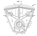
図1は、閉鎖された、非分注位置の場合の、本発明の分注用クロージャ10の好ましい実施形態を示している。クロージャ10は、首部210(図8および図9を参照されたい)または他の適切な構造体によって画定される従来の開放口を有する場合もある容器200(図8および図9を参照されたい)に取り付けられるように適応される。容器は、最も一般的には、容器から中身を分注するのを助けるようにユーザによって押し潰され得る概ね可撓性壁部を有するタイプのものであるが、これに限定されるものではない。
FIG. 1 shows a preferred embodiment of the dispensing
クロージャ10は、容器200に取り付けるためのハウジング14(図1から図4、図8から図11)を含んでいる。ハウジング14は、概ね卵形円筒形の外壁16を含む。上部表面180を有する概ね横向きのクロージャ壁または床18(図3、図4、図8から図11)は、ハウジング14の中に成形されるアクチュエータ受け15を横切って延在する。アクチュエータ受け15は、直径方向に対向する受け壁11および前壁13によってさらに画定される。直径方向に対向する屋根セグメント19および送り出しポスト87が、開口受け15の側面に位置する。第2の好ましい実施形態では、受け15および床18は、壁11が外壁16(図示せず)の一部と一致する外壁16によって画定されるハウジングの周面に延在する。アクチュエータ50は、この第2の実施形態の場合、屋根セグメント19に取って代わる。
The
ハウジング14の内部円筒壁21は、相補的な容器のスナップ式ビード230の場合と同様に、容器口部220の周りに容器首部210の頂部の外周に係合するようにスナップ式ビード190を通して適応される(図4および図8から図11)。他の適切な係合手段(たとえば、ねじまたは任意の適切な等価物)が、容器200にハウジング14を固定するように設けられ得る。あるいは、いくつかの分野では、ハウジング14は、容器200に解放不能に取り付けられ、または容器200と一体に形成されることもできる。
The inner
環状封止リング20が、図4および図8から図11に示されるように、密封シールを行う容器口部のところで容器首部210の内部端縁に係合するために設けられ得る。
An
ハウジング14は、図3、図4および図8から図10に示されるように床18を通して吐出開口または通路30を含んでいる。好ましい実施形態では、ハウジング14は、床18から上方に突出する吐出管32を含み、吐出開口30は、管32と流体連通している。管32の吐出開口30は、管32の下端部で内部の任意の容器200と床18を通して連通する。
The
図3、図4および図8から図11に示されるように、ハウジング14の卵形円筒形の外壁16は、床18の周りに延在する。床18に隣接する壁16の後方部分は、壁13に対向する壁16の後方部分の上縁にカットアウトまたはノッチの形の指掛け凹部領域34を部分的に画定する。
As shown in FIGS. 3, 4 and 8 to 11, the oval cylindrical
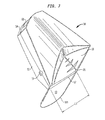
ハウジング14は、アクチュエータ50を受け入れる。アクチュエータ50は、頂部後方壁80を有する横頂部壁52、前方周囲フランジ54、および直径方向に対向する側部フランジ59を含む。頂部後方壁80に隣接して、後方フランジ55を上部後方フランジ91と下部リム101を備える下部後方フランジ93に分割する関節運動可能なヒンジ57を有する後方フランジ55がある(図1、図2、図5から図9、および図11)。2つの対向する側部フランジ59のそれぞれにおいて、好ましくは平坦化された面を備える、突出している半球体突起またはピボット部材56がある(図6および図7)。
The
好ましい実施形態では、ピボット部材56は、ハウジング14内で枢動運動のためにアクチュエータ50を非対称に取り付けるように凹部58を通して受け壁11と協働する。このために、受け壁11は、ピボット部材56のスナップ作用係合を行うようにピボット部材56のうちの1つとそれぞれ合わさるための凹部58をそれぞれ画定する(図3)。これは、ピボット部材56を接合する線によって画定される枢動軸を中心にしてアクチュエータ50の枢動運動を受け入れ、枢動軸は、横床18に平行であり、ハウジング14内に非対称に配置される。
In the preferred embodiment, the
壁11の頂部端縁には、各凹部58の上に、組立てを容易にするために面取り部(図示せず)が設けられ得る。ハウジング14およびアクチュエータ50が組み立てられると、アクチュエータのピボット部材56およびハウジングの凹部58は、図2に示されるようにノズル60が壁11および13の上に露出されるまでアクチュエータ50が(アクチュエータ50の後方部分でユーザが下方に押すことによって)枢動され得るように、取付構造体の一部として機能する。開口凹部がハウジング外壁16に延在する、上記で参照された第2の好ましい実施形態では、ピボット部材56は、壁16によって画定される相補的な凹部を通して壁16と協働し、ここに、受け15および壁11は、壁16と一致するハウジング14の周囲に延在する。
A chamfered portion (not shown) may be provided on the top edge of the
アクチュエータ50は、ノズル60と連通する導管構造体61を含み、床105は、頂部壁52の底面に連結される。アクチュエータは、その配向に応じて、吐出管32およびノズル60から流動性材料を分注できるようにし、またはノズル60からの流れを防止するように管32を塞ぐ働きをする。特に、図5、図6、図8および図9に示されるように、導管構造体61は、段のある円筒形封止壁69と流体連通する。
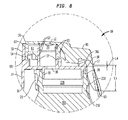
図1および図8に示されるようにアクチュエータ50が閉鎖された位置にある場合、壁69は、吐出管32の上部周辺部を取り囲み、密封する。封止プラグ76が、アクチュエータ頂部壁52の底部から下方に突出することが好ましい。封止プラグ76は、概ね円筒形または環状の形状構成を有し、図1および図8に示されるようにアクチュエータが閉鎖された位置にある場合、吐出開口30および管32を塞ぐように吐出管32の頂部において開口に密封係合するように適応される。管32および壁69は、クロージャの早過ぎる開口を防ぐのを助ける摺動抵抗を与えるように協働する。
When the
他方では、図2および図9に示されるように、アクチュエータ50の頂部後方壁が分注位置にアクチュエータを傾斜させるように下方に押されると、この場合、封止プラグ76の前方部分が、吐出管32の頂部から遠ざかるように傾斜されて、導管61および分注ノズル60を通して吐出開口30から管32に材料の流れを可能にする。図2および図9に示されるように、アクチュエータ50が分注位置に傾斜されると、壁69(図5および図9)は、容器の中身が導管61の中に分注されるが吐出管32の頂部の周りに漏れ出ることができないように、吐出管32の上端の外周を引き続き密封する。
On the other hand, as shown in FIGS. 2 and 9, when the top rear wall of the
アクチュエータ50は、アクチュエータ50の頂部後方壁80のところで下方に方向付けられる力を加えることによって、開いた位置に枢動され得る。このために、頂部後方壁80は、親指または指の端部を受け入れるために窪み内に凹設されることが好ましい(図1、図2、図5および図7から図9)。好ましい実施形態では、アクチュエータ50は、床18に堅固に取り付けられる軸受83に回転可能に係合する頂部壁52の底面に堅固に連結される車軸81を有する(図3および図6)。アクチュエータ50は、さらに、頂部壁52の底面に堅固に連結されるピボット支持体85によって支持され、アクチュエータ50が枢動しながら床18と押圧係合していることが好ましい。
The
本発明によれば、変形可能な一体のヒンジ57は、開いた分注配向へのアクチュエータ50の偶発的な移動を防止し、クロージャのハウジング14の中にアクチュエータを容易に組み立てできるように設けられる。これにより、消費者による使用の前の発送および大雑把な取り扱い中に、不注意による作動に耐えるクロージャが提供される。
In accordance with the present invention, a deformable
クロージャ10が任意の容器200を密封係合する場合の操作では、下部後方フランジ93は、十分に大きな力がアクチュエータ50の頂部後方部分に故意に加えられるまで、このような不注意による作動に対する抵抗力の一部を与える働きをする容器200の隣接する部分に押圧係合する(図8)。この好ましい実施形態においてアクチュエータ50の不注意による作動を防止する追加の任意の力は、摺動抵抗を含み、送り出しポスト87はアクチュエータ50に備えてあり、摺動抵抗壁69は吐出管32に備えている。十分なレベルの力がアクチュエータ50の頂部、後方部分に加えられると、下部後方フランジ93は、(ノズルから遠ざかって)指掛け凹部領域34に向かって偏向される(図9)。同時に、アクチュエータ50は、送り出しポスト87の下に押され、壁69は、管32の上に駆り立てられる。発送および取扱い中にアクチュエータが加えられ得る力は、通常、下部後方フランジ93を偏向させまたは変形させるのに、ならびにアクチュエータを傾斜させる他の抵抗源に打ち勝つのに不十分である。したがって、アクチュエータ50は、閉鎖された非分注位置から遠ざかるようにいかなる意味のある程度にも傾斜され得ない。
In operation when the
しかしながら、その後、消費者がクロージャを使用することを望む場合、消費者は、初めに、実質的により大きな力をアクチュエータ50の頂部後方壁80に加える。所定の力以上の力が、指掛け凹部領域34に向かってヒンジ57に沿って下部後方フランジ93を偏向させるのに十分な力で、送り出しポスト87を通過したアクチュエータ50、管32を通過した壁69、および容器200に対する下部後方フランジ93を同時に作動し、その結果、上述のようにアクチュエータ50の開口をもたらす(図9)。
However, if the consumer subsequently desires to use the closure, the consumer first applies a substantially greater force to the top
上述した後方フランジ保持構造体は、クロージャアクチュエータにたやすく成形され得る。従来の金型は、この特徴を含むように比較的容易に新たな改善を施され得る。 The rear flange holding structure described above can be easily molded into a closure actuator. Conventional molds can be renewed relatively easily to include this feature.
本発明の1つの態様には、任意の容器200に対して使用するためのトグル式分注用クロージャ10があり、クロージャは:
a.横床18および外壁16を有するハウジング14と、
b.横床18の上に横たわる頂部後方壁80を含む頂部壁52を有し、ノズル床105を備えるノズル開口60を画定するアクチュエータ50であり、閉鎖された非分注位置と開いた分注位置との間を移動できるようにハウジング14の内側に非対称にかつ枢動可能に取り付けられるアクチュエータ50と、
c.ハウジング14内の第1の位置において頂部後方壁80の下に延在する後方アクチュエータフランジ55と、
d.後方フランジ55を頂部後方壁80に隣接する上部後方フランジ91と後方フランジリム101に隣接する下部後方フランジ93とに分割する長軸を備えるヒンジ57を有する後方フランジ55とを含み、
e.それによってヒンジの長軸は、横床18に実質的に平行に方向付けられる。
One aspect of the present invention includes a
a. A
b.
c. A
d. Look including a
e. Thereby, the long axis of the hinge is oriented substantially parallel to the
実質的に平行であるとは、上述のように、ヒンジの配向がクロージャの不注意な開口を防止するのみならずまたハウジングの中へのアクチュエータの組立てを容易にする働きをする場合に、平行またはほぼ平行であるものと規定される。 Substantially parallel, as described above, is parallel if the orientation of the hinge not only prevents inadvertent opening of the closure, but also facilitates assembly of the actuator into the housing. Or it is defined to be approximately parallel.
クロージャは、
a.ノズル床105に直角な長さL1を有し、かつノズル床に対向する前方フランジリム103の方に延在するハウジング14内にノズル床105の下に延在する前方アクチュエータフランジ54をさらに含み、
b.後方フランジ55は、頂部後方壁80に直角な長さL2を有し、頂部壁52に対向する後方フランジリム101の方に延在し、
c.L1とL2との比は、0.1から0.33までの範囲にあることが有利である。
Closure
a. Have perpendicular length L1 to the
b. The
c. The ratio between L1 and L2 is advantageously in the range from 0.1 to 0.33.
L1は、好ましくは約6mm、より好ましくは約1mmから約6mmまでの範囲、最も好ましくは約3mmの最大長さを有する。L2は、好ましくは約18mm、より好ましくは約8mmから約18mmまでの範囲、最も好ましくは約15mmの最大長さを有する。L1とL2との比は、約0.2であることが好ましい。 L1 preferably has a maximum length in the range of about 6 mm, more preferably from about 1 mm to about 6 mm, and most preferably about 3 mm. L2 preferably has a maximum length in the range of about 18 mm, more preferably from about 8 mm to about 18 mm, and most preferably about 15 mm. The ratio between L1 and L2 is preferably about 0.2.
ヒンジ57は、好ましくは外側ハウジング壁16から間隔を置いて配置され、長さL3を有し、このヒンジが曲げられない場合に横床18の上部表面180に直角な線に沿ってL4の距離のところに配置される。L3は、好ましくは約7mm、より好ましくは約7mmから40mmまでの範囲、最も好ましくは約25mmの最小長さを有する。L4は、好ましくは0.1mmの最小値を有し、より好ましくはL4は、約1mm以下であり、最も好ましくは約1mmよりも小さい。ヒンジ57は、このヒンジが曲げられない場合にヒンジに直角な線に沿ってL5の距離のところに配置され、下部後方フランジリムの方に延在する。L4とL5との比は、0.01から0.20までの範囲にあることが好ましい(約0.03であることが有利である)。好ましい実施形態では、L5は約12mmである。
The
下部後方フランジ93は、クロージャ10が密封係合される任意の容器200に弾性接触するように適合され、それによって、下部後方フランジ93は、ノズル(Nozzle)に対向するアクチュエータの後方頂部壁80(「第1の位置」)において第1の力を加えることに応じて前記容器100の上のアクチュエータ50の移動を防止するが、前記第1の位置において下方に加えられる実質的により大きな第2の力に応じて前記アクチュエータ50の移動ができるようにすることが有利である。
The lower
好ましい実施形態では、ヒンジは、アクチュエータに一体に成形される、厚さが1mm以下のプラスチックの薄肉領域である。アクチュエータは、熱可塑性材料を含むが、これに限定されず、後方下部フランジは、25℃において弾性的であり、ユーザがクロージャを開くようにアクチュエータの後部に適度の力を加えると曲がり得ることが好ましい。この開口の力は、約25ニュートンから約50ニュートン(5.6ポンドフィートから11ポンドフィート)までの範囲、最適には、約30ニュートンまたは約35ニュートンの最小量および約40ニュートンまたは約45ニュートンの最大量であることが好ましい。アクチュエータの熱可塑性曲げ弾性率の範囲は、25℃において約600MPa(メガパスカル)から約2000MPaまでの範囲であることが好ましい。 In a preferred embodiment, the hinge is a thin plastic area less than 1 mm thick that is integrally formed with the actuator. The actuator includes, but is not limited to, thermoplastic material, and the rear lower flange is elastic at 25 ° C. and may bend when a moderate force is applied to the rear of the actuator to allow the user to open the closure. preferable. The force of this opening ranges from about 25 Newtons to about 50 Newtons (5.6 pound feet to 11 pound feet), optimally a minimum amount of about 30 Newtons or about 35 Newtons and about 40 Newtons or about 45 Newtons. The maximum amount is preferred. The range of the thermoplastic flexural modulus of the actuator is preferably in the range from about 600 MPa (megapascal) to about 2000 MPa at 25 ° C.
ハウジングに対してアクチュエータの回転軸は、ハウジングの中心線から少なくとも80%偏位していることが好ましく、ここに0%は、対称回転が可能であり、100%は、ハウジング内でいかなる回転もできない。 The axis of rotation of the actuator relative to the housing is preferably at least 80% offset from the center line of the housing, where 0% is capable of symmetrical rotation and 100% is free of any rotation within the housing. Can not.
本発明のクロージャは、熱可塑性材料から難なく成形され、流線形状の製品を形成するように容易に組み立てられ得る。緊密な係合がアクチュエータとハウジングとの間、およびハウジングと容器との間に確立されなければならないので、ポリプロピレンおよびポリエチレンなどの熱可塑性樹脂が、使用されることが好ましい。本発明のクロージャに対して使用され得る適切な容器は、容器が手で押し潰され、回復時に速やかに元の形状に復元され得るようになる材料で作られることが好ましい。適切な材料の例には、ポリプロピレン、ポリエチレン、ポリエチレンテレフタラート、ポリ塩化ビニル、ナイロン、またはそれらの積層物等のような熱可塑性樹脂がある。 The closure of the present invention can be easily molded from a thermoplastic material and easily assembled to form a streamlined product. Thermoplastic resins such as polypropylene and polyethylene are preferably used because a tight engagement must be established between the actuator and the housing and between the housing and the container. Suitable containers that can be used for the closures of the present invention are preferably made of a material that allows the containers to be crushed by hand and quickly restored to their original shape upon recovery. Examples of suitable materials include thermoplastic resins such as polypropylene, polyethylene, polyethylene terephthalate, polyvinyl chloride, nylon, or laminates thereof.
本発明をその特定の実施形態に関して説明したが、当業者には本発明の多数の他の形態および改変が明白であることは明らかである。添付の特許請求の範囲および本発明は、一般に、本発明の真の趣旨および範囲内にあるすべてのこのような明らかな形態および改変に適用されるものと解釈されるべきである。 Although the invention has been described with reference to specific embodiments thereof, it will be apparent to those skilled in the art that many other forms and modifications of the invention are apparent. The appended claims and this invention should generally be construed to apply to all such obvious forms and modifications within the true spirit and scope of this invention.
Claims (5)
前記クロージャ(10)が、横床(18)および外壁(16)を有するハウジング(14)と、アクチュエータ(50)とを有し、該アクチュエータ(50)が、前記横床(18)の上に横たわる頂部後方壁(80)を含む頂部壁(52)を有し、ノズル床(105)を備えるノズル開口(60)を画定し、
a.前記アクチュエータ(50)が、閉鎖された非分注位置と開いた分注位置との間を移動のために前記ハウジング(14)の内側に枢動可能に取り付けられ、
b.前記アクチュエータ(50)が、長軸を備えるヒンジ(57)を有する後方フランジ(55)を有し、前記ヒンジ(57)が、前記後方フランジ(55)を前記頂部後方壁(80)に隣接する上部後方フランジ(91)と後方フランジリム(101)に隣接する下部後方フランジ(93)とに分割し、
c.それによって、前記ヒンジの前記長軸が、前記横床(18)に実質的に平行に方向付けられ、
前記後方フランジ(55)が、前記ハウジング(14)内で前記頂部後方壁(80)の下方に延在し、
前記後方フランジリム(101)は、前記頂部後方壁(80)の下方において延びており、前記外壁(16)には取り付けられておらず、これにより、前記アクチュエータは、該アクチュエータの前記頂部後方壁が下方に押圧されることによって、枢動することが可能となっており、
前記下部後方フランジは、前記クロージャが密封係合される任意の容器に弾性接触するように適合され、それによって、前記下部後方フランジが、前記アクチュエータの前記頂部後方壁において第1の力を加えることに応じて前記容器の上の前記アクチュエータの移動を防止するが、前記アクチュエータの前記頂部後方壁において下方に加えられる実質的により大きな第2の力に応じて前記アクチュエータを移動できるようにし、
前記アクチュエータは、前記ハウジングに対して非対称に取り付けられている、
ことを特徴とする、クロージャ。 A toggle dispensing closure (10) for use with any container (200) comprising:
Wherein the closure (10), a housing (14) having a transverse floor (18) and outer wall (16), and an actuator (50), the actuator (50) is, on the horizontal floor (18) Defining a nozzle opening (60) having a top wall (52) including a lying top rear wall (80) and comprising a nozzle bed (105);
a. It said actuator (50) is pivotally mounted inside the housing (14) for movement between a dispensing position and an open closed unbranched dispensing position,
b. It said actuator (50) has a rear flange (55) having a hinge (57) having a longitudinal axis, said hinge (57) is adjacent said rear flange (55) on the top rear wall (80) Divided into an upper rear flange (91) and a lower rear flange (93) adjacent to the rear flange rim (101);
c. Whereby the long axis of the hinge is substantially oriented parallel to the horizontal floor (18),
The rear flange (55) is extending under side of the housing (14) within said top rear wall (80),
The rear flange rim (101) extends below the top rear wall (80) and is not attached to the outer wall (16) , whereby the actuator is mounted on the top rear wall of the actuator. Can be pivoted by being pressed downward,
The lower rear flange is adapted to resiliently contact any container in which the closure is hermetically engaged so that the lower rear flange applies a first force at the top rear wall of the actuator. The actuator on the container is prevented from moving in response to allowing the actuator to move in response to a substantially larger second force applied downward in the top rear wall of the actuator;
The actuator is mounted asymmetrically with respect to the housing;
A closure characterized by that.
b.前記後方フランジが、前記頂部後方壁に垂直な長さL2を有し、該頂部後方壁に対向する後方フランジリムの方に延在し、
c.L1とL2との比が、約0.1から0.33までの範囲にある請求項1に記載のクロージャ。 a. Having said nozzle floor perpendicular length L1, and further comprising a front actuator flange extending below side of the nozzle floor in the housing which extends towards the forward flange rim opposed to the nozzle floor ,
b. The rear flange has a vertical length L2 in the top rear wall, extending toward the rear flange rim opposed to the top rear wall,
c. The closure of claim 1 wherein the ratio of L1 to L2 is in the range of about 0.1 to 0.33.
前記ヒンジは、該ヒンジが曲げられない場合に前記横床の上部表面に垂直な線に沿ってL4の距離のところに配置され、前記ヒンジが曲げられない場合に該ヒンジの前記長軸に垂直な線に沿ってL5の距離のところに配置されかつ前記下部後方フランジリムの方に延在し、
L4とL5との比が、約0.01から0.20までの範囲にある、請求項1に記載のクロージャ。 The hinge is disposed at a distance from the outer wall of the housing, it has a length L3,
Wherein the hinge is located at a distance of the hinge along a line perpendicular to the top surface of the horizontal floor when not bent L4, perpendicular to the long axis of the hinge when the hinge is not bent Arranged at a distance of L5 along a straight line and extending towards said lower rear flange rim,
The closure of claim 1, wherein the ratio of L4 to L5 is in the range of about 0.01 to 0.20.
Applications Claiming Priority (3)
| Application Number | Priority Date | Filing Date | Title |
|---|---|---|---|
| US12/432,085 US8074849B2 (en) | 2009-04-29 | 2009-04-29 | Toggle action dispensing closure with articulated rear flange |
| US12/432,085 | 2009-04-29 | ||
| PCT/EP2010/055325 WO2010124983A1 (en) | 2009-04-29 | 2010-04-22 | Toggle-action dispensing closure with articulated rear flange |
Publications (3)
| Publication Number | Publication Date |
|---|---|
| JP2012525302A JP2012525302A (en) | 2012-10-22 |
| JP2012525302A5 JP2012525302A5 (en) | 2013-05-16 |
| JP6027438B2 true JP6027438B2 (en) | 2016-11-16 |
Family
ID=42288904
Family Applications (1)
| Application Number | Title | Priority Date | Filing Date |
|---|---|---|---|
| JP2012507685A Expired - Fee Related JP6027438B2 (en) | 2009-04-29 | 2010-04-22 | Toggle type dispensing closure with articulated rear flange |
Country Status (16)
| Country | Link |
|---|---|
| US (1) | US8074849B2 (en) |
| EP (1) | EP2424785B1 (en) |
| JP (1) | JP6027438B2 (en) |
| KR (1) | KR101655496B1 (en) |
| CN (1) | CN102421675B (en) |
| AR (1) | AR078036A1 (en) |
| AU (1) | AU2010243760B2 (en) |
| BR (1) | BRPI1007589B1 (en) |
| CA (1) | CA2755702C (en) |
| CL (1) | CL2011002686A1 (en) |
| CO (1) | CO6361977A2 (en) |
| EA (1) | EA019743B1 (en) |
| ES (1) | ES2409121T3 (en) |
| MX (1) | MX2011011354A (en) |
| WO (1) | WO2010124983A1 (en) |
| ZA (1) | ZA201106078B (en) |
Families Citing this family (9)
| Publication number | Priority date | Publication date | Assignee | Title |
|---|---|---|---|---|
| US8813982B2 (en) | 2011-09-28 | 2014-08-26 | The Procter & Gamble Company | Cap for a container |
| ES2525891B1 (en) * | 2013-06-25 | 2015-09-28 | Aguas De Solán De Cabras, S.A. | Closure cap for liquid containers |
| EA032262B1 (en) * | 2015-03-20 | 2019-04-30 | Юнилевер Н.В. | Closure assembly for a container |
| JP6776268B2 (en) * | 2015-06-08 | 2020-10-28 | ユニリーバー・ナームローゼ・ベンノートシヤープ | Container lid assembly |
| JP6652876B2 (en) * | 2015-08-04 | 2020-02-26 | サーモス株式会社 | Cap unit and beverage container |
| CN111527031B (en) | 2017-12-28 | 2022-01-18 | 联合利华知识产权控股有限公司 | Closure member |
| USD878918S1 (en) | 2018-06-01 | 2020-03-24 | S. C. Johnson & Son, Inc. | Actuator overcap |
| US20210147123A1 (en) * | 2019-11-18 | 2021-05-20 | Johnson & Johnson Consumer Inc. | Closure for personal care product container |
| US20230023955A1 (en) * | 2020-01-28 | 2023-01-26 | Aptargroup, Inc. | Dispensing Closure |
Family Cites Families (42)
| Publication number | Priority date | Publication date | Assignee | Title |
|---|---|---|---|---|
| US558810A (en) * | 1896-04-21 | Hat-finishing lathe | ||
| US3516581A (en) * | 1968-09-06 | 1970-06-23 | Robert D Wise | Toggle type closure |
| JPS549565Y2 (en) * | 1973-02-21 | 1979-05-04 | ||
| JPS5444046Y2 (en) * | 1974-09-30 | 1979-12-18 | ||
| US4545086A (en) | 1976-05-17 | 1985-10-08 | Milliken Research Corporation | Pattern designs printed with computer controlled pattern dyeing device |
| JPS5620370Y2 (en) * | 1976-06-23 | 1981-05-14 | ||
| US4776501A (en) * | 1987-08-31 | 1988-10-11 | Seaquist Closures | Self-closing, press-to-open, dispensing closure |
| US4962869A (en) | 1989-04-11 | 1990-10-16 | Sequist Closures | Toggle-acting dispensing closure with impact resistance |
| US5058775A (en) * | 1989-05-02 | 1991-10-22 | Seaquist Closures, A Division Of Pittway Corporation | Toggle-acting dispensing closure with premature actuation prevention means |
| DE3922258C1 (en) * | 1989-07-06 | 1990-08-09 | Bielsteiner Verschlusstechnik Gmbh, 5270 Gummersbach, De | |
| DE4017985A1 (en) | 1990-06-05 | 1991-12-12 | Finke Robert Gmbh | Tilt lock |
| FR2675403B1 (en) * | 1991-04-19 | 1993-08-13 | Oreal | DEVICE FOR DISSEMINATING A LIQUID PRODUCT, IN PARTICULAR A HAIR PRODUCT, IN FINE DROPS. |
| US5279451A (en) * | 1992-03-06 | 1994-01-18 | Aptargroup, Inc. | Dispensing closure with twist collar |
| ATE178552T1 (en) | 1993-06-10 | 1999-04-15 | Procter & Gamble | CLOSURE-PROOF TIP LOCK |
| US5341960A (en) * | 1993-12-17 | 1994-08-30 | Aptargroup, Inc. | Toggle-action dispensing closure with capture structure for severable actuation-prevention abutment |
| US5346100A (en) * | 1994-01-14 | 1994-09-13 | Aptargroup, Inc. | Toggle-action dispensing closure with an actuation-prevention abutment and a fracture control surface |
| US5370284A (en) * | 1994-03-15 | 1994-12-06 | The Procter & Gamble Company | Toggle closure for a resiliently deformable container |
| JP3025863U (en) * | 1995-09-22 | 1996-06-25 | 岩崎 満男 | Caps for containers such as powder |
| DE19541830A1 (en) | 1995-11-10 | 1997-05-15 | Innocos Gmbh | Closure device for containers |
| US5709318A (en) * | 1996-01-31 | 1998-01-20 | The Procter & Gamble Company | Dispensing closure with integral locking switch and tamper evidency structure |
| US5918777A (en) * | 1996-02-21 | 1999-07-06 | Owens-Brockway Plastic Products Inc. | Dispensing package for viscous liquid product |
| US5862963A (en) * | 1997-08-06 | 1999-01-26 | Owens-Illinois Closure Inc. | Dispensing closure |
| US5873494A (en) * | 1997-09-05 | 1999-02-23 | Aptargroup, Inc. | Dual stream liquid dispensing structure |
| WO1999036328A1 (en) | 1998-01-20 | 1999-07-22 | The Procter & Gamble Company | Dispensing closure with integral locking switch and tamper evidency structure |
| US6029866A (en) * | 1998-09-29 | 2000-02-29 | Aptargroup, Inc. | Multiple injection, toggle-action dispensing structure |
| AU2253201A (en) | 1999-12-03 | 2001-06-12 | Sussex Technology, Inc. | Toggle action dispensing closure with locking means |
| US6343725B1 (en) * | 2000-12-19 | 2002-02-05 | Owens-Illinois Closure Inc. | Disk-type toggle-action dispensing closure, package and method of assembly |
| US6283333B1 (en) * | 2001-01-17 | 2001-09-04 | Seaquist Closures Foreign, Inc. | Toggle-action dispensing closure with an actuation-prevention abutment and a recessed striker rib |
| US6564978B1 (en) * | 2001-02-12 | 2003-05-20 | Owens-Brockway Plastic Products Inc. | Disk-top fluid dispensing package |
| US6691394B1 (en) * | 2001-02-12 | 2004-02-17 | Owens-Brockway Plastic Products Inc. | Disk-top fluid dispensing package |
| US6460729B2 (en) | 2001-03-06 | 2002-10-08 | Doly-Seal Corporation | One-piece side-dispensing closure |
| JP3953318B2 (en) * | 2001-12-28 | 2007-08-08 | 株式会社ニフコ | cap |
| US6739781B2 (en) * | 2002-04-22 | 2004-05-25 | Seaquist Closures Foreign, Inc. | Scrubbing structure |
| US20020179644A1 (en) * | 2002-05-30 | 2002-12-05 | Evans Christopher T. | Toggle action dispensing closure with locking means |
| US6896160B2 (en) * | 2002-12-12 | 2005-05-24 | Poly-Seal Corporation | Lockable disc top dispensing closure |
| US6971547B2 (en) * | 2003-02-05 | 2005-12-06 | Berry Plastics Corporation | Dispensing package with lockable closure |
| US6832700B2 (en) * | 2003-02-18 | 2004-12-21 | Seaquist Closures Foreign, Inc. | Toggle-action dispensing closure with an actuation-prevention system incorporating permanent deformation |
| JP4443151B2 (en) * | 2003-06-25 | 2010-03-31 | 株式会社吉野工業所 | Hinge cap |
| US7806302B2 (en) * | 2005-02-24 | 2010-10-05 | Joseph S Kanfer | Personal fluid dispensers with features for aiding portability and use |
| DE102005041702A1 (en) * | 2005-09-02 | 2007-03-08 | Wella Ag | Cap for a container |
| DE102005041701A1 (en) * | 2005-09-02 | 2007-03-08 | Wella Ag | Cap for a container |
| GB2434574A (en) | 2006-01-27 | 2007-08-01 | Obrist Closures Switzerland | A dispensing closure |
-
2009
- 2009-04-29 US US12/432,085 patent/US8074849B2/en active Active
-
2010
- 2010-04-22 JP JP2012507685A patent/JP6027438B2/en not_active Expired - Fee Related
- 2010-04-22 CA CA2755702A patent/CA2755702C/en active Active
- 2010-04-22 CN CN201080018927.8A patent/CN102421675B/en active Active
- 2010-04-22 KR KR1020117025615A patent/KR101655496B1/en active IP Right Grant
- 2010-04-22 EP EP10717594A patent/EP2424785B1/en active Active
- 2010-04-22 EA EA201171315A patent/EA019743B1/en not_active IP Right Cessation
- 2010-04-22 MX MX2011011354A patent/MX2011011354A/en active IP Right Grant
- 2010-04-22 WO PCT/EP2010/055325 patent/WO2010124983A1/en active Application Filing
- 2010-04-22 ES ES10717594T patent/ES2409121T3/en active Active
- 2010-04-22 AU AU2010243760A patent/AU2010243760B2/en active Active
- 2010-04-22 BR BRPI1007589-5A patent/BRPI1007589B1/en active IP Right Grant
- 2010-04-27 AR ARP100101409A patent/AR078036A1/en active IP Right Grant
-
2011
- 2011-08-18 ZA ZA2011/06078A patent/ZA201106078B/en unknown
- 2011-08-30 CO CO11111156A patent/CO6361977A2/en active IP Right Grant
- 2011-10-27 CL CL2011002686A patent/CL2011002686A1/en unknown
Also Published As
| Publication number | Publication date |
|---|---|
| JP2012525302A (en) | 2012-10-22 |
| AU2010243760B2 (en) | 2013-09-19 |
| CN102421675B (en) | 2015-07-01 |
| EP2424785B1 (en) | 2013-03-27 |
| EP2424785A1 (en) | 2012-03-07 |
| MX2011011354A (en) | 2011-11-18 |
| EA019743B1 (en) | 2014-05-30 |
| CL2011002686A1 (en) | 2012-06-22 |
| KR101655496B1 (en) | 2016-09-07 |
| US8074849B2 (en) | 2011-12-13 |
| CO6361977A2 (en) | 2012-01-20 |
| AU2010243760A1 (en) | 2011-09-08 |
| BRPI1007589A2 (en) | 2016-02-16 |
| ZA201106078B (en) | 2012-10-31 |
| AR078036A1 (en) | 2011-10-12 |
| BRPI1007589B1 (en) | 2019-11-05 |
| EA201171315A1 (en) | 2012-05-30 |
| CA2755702C (en) | 2018-01-02 |
| KR20120013352A (en) | 2012-02-14 |
| ES2409121T3 (en) | 2013-06-25 |
| CN102421675A (en) | 2012-04-18 |
| CA2755702A1 (en) | 2010-11-04 |
| WO2010124983A1 (en) | 2010-11-04 |
| US20100276460A1 (en) | 2010-11-04 |
Similar Documents
| Publication | Publication Date | Title |
|---|---|---|
| JP6027438B2 (en) | Toggle type dispensing closure with articulated rear flange | |
| US4776501A (en) | Self-closing, press-to-open, dispensing closure | |
| US4911337A (en) | Snap-action closure with disengagable spring having stress relieved positions | |
| KR101900419B1 (en) | Dual container | |
| US6991126B2 (en) | Dispensing closure for a container that holds pourable material | |
| EP0410858A2 (en) | Assembly for dispensing at least one fluid product such as cosmetics or pharmaceutics | |
| JPH11100059A (en) | Portioning cap for product | |
| AU2004213363B2 (en) | Toggle-action closure | |
| EP3849916B1 (en) | Closure for a container | |
| US10518945B2 (en) | Closure for a container | |
| CA2280177C (en) | Snap-action closure with disengaged compression member | |
| JP2021519246A (en) | Flip top cap for dispensing fluid dental material | |
| RU2404906C2 (en) | Distribution caps for liquid containers | |
| CA2156513A1 (en) | Closure with two-part slidable dispensing cap | |
| EP0957035A1 (en) | Pour spout having dosing means | |
| JP7455028B2 (en) | discharge cap | |
| JP2000272649A (en) | Cap for container | |
| US10112818B1 (en) | Liquid dispensing tap and closure assembly therefor | |
| JP4683264B2 (en) | Cap for extraction | |
| EP4087795A1 (en) | One-piece spray cap with monolithically formed locking member and actuating member | |
| JP2000318755A (en) | Cap having small lid | |
| JP2007015714A (en) | Slant pouring hinged cap and spout | |
| JP2007119051A (en) | Hinge cap |
Legal Events
| Date | Code | Title | Description |
|---|---|---|---|
| A621 | Written request for application examination |
Free format text: JAPANESE INTERMEDIATE CODE: A621 Effective date: 20130222 |
|
| A521 | Request for written amendment filed |
Free format text: JAPANESE INTERMEDIATE CODE: A523 Effective date: 20130327 |
|
| RD03 | Notification of appointment of power of attorney |
Free format text: JAPANESE INTERMEDIATE CODE: A7423 Effective date: 20131022 |
|
| A977 | Report on retrieval |
Free format text: JAPANESE INTERMEDIATE CODE: A971007 Effective date: 20131226 |
|
| A131 | Notification of reasons for refusal |
Free format text: JAPANESE INTERMEDIATE CODE: A131 Effective date: 20140107 |
|
| A601 | Written request for extension of time |
Free format text: JAPANESE INTERMEDIATE CODE: A601 Effective date: 20140407 |
|
| A602 | Written permission of extension of time |
Free format text: JAPANESE INTERMEDIATE CODE: A602 Effective date: 20140414 |
|
| A521 | Request for written amendment filed |
Free format text: JAPANESE INTERMEDIATE CODE: A523 Effective date: 20140507 |
|
| A02 | Decision of refusal |
Free format text: JAPANESE INTERMEDIATE CODE: A02 Effective date: 20141202 |
|
| A521 | Request for written amendment filed |
Free format text: JAPANESE INTERMEDIATE CODE: A523 Effective date: 20150325 |
|
| A911 | Transfer to examiner for re-examination before appeal (zenchi) |
Free format text: JAPANESE INTERMEDIATE CODE: A911 Effective date: 20150407 |
|
| A912 | Re-examination (zenchi) completed and case transferred to appeal board |
Free format text: JAPANESE INTERMEDIATE CODE: A912 Effective date: 20150515 |
|
| A601 | Written request for extension of time |
Free format text: JAPANESE INTERMEDIATE CODE: A601 Effective date: 20160302 |
|
| A521 | Request for written amendment filed |
Free format text: JAPANESE INTERMEDIATE CODE: A523 Effective date: 20160502 |
|
| A61 | First payment of annual fees (during grant procedure) |
Free format text: JAPANESE INTERMEDIATE CODE: A61 Effective date: 20161014 |
|
| R150 | Certificate of patent or registration of utility model |
Ref document number: 6027438 Country of ref document: JP Free format text: JAPANESE INTERMEDIATE CODE: R150 |
|
| R250 | Receipt of annual fees |
Free format text: JAPANESE INTERMEDIATE CODE: R250 |
|
| R250 | Receipt of annual fees |
Free format text: JAPANESE INTERMEDIATE CODE: R250 |
|
| R250 | Receipt of annual fees |
Free format text: JAPANESE INTERMEDIATE CODE: R250 |
|
| S111 | Request for change of ownership or part of ownership |
Free format text: JAPANESE INTERMEDIATE CODE: R313113 |
|
| R350 | Written notification of registration of transfer |
Free format text: JAPANESE INTERMEDIATE CODE: R350 |
|
| LAPS | Cancellation because of no payment of annual fees |