JP6027138B2 - Ophthalmic integrated device - Google Patents
Ophthalmic integrated device Download PDFInfo
- Publication number
- JP6027138B2 JP6027138B2 JP2014549367A JP2014549367A JP6027138B2 JP 6027138 B2 JP6027138 B2 JP 6027138B2 JP 2014549367 A JP2014549367 A JP 2014549367A JP 2014549367 A JP2014549367 A JP 2014549367A JP 6027138 B2 JP6027138 B2 JP 6027138B2
- Authority
- JP
- Japan
- Prior art keywords
- optical
- radiation
- ophthalmic
- unit
- branch
- Prior art date
- Legal status (The legal status is an assumption and is not a legal conclusion. Google has not performed a legal analysis and makes no representation as to the accuracy of the status listed.)
- Active
Links
Images


Classifications
-
- A—HUMAN NECESSITIES
- A61—MEDICAL OR VETERINARY SCIENCE; HYGIENE
- A61B—DIAGNOSIS; SURGERY; IDENTIFICATION
- A61B3/00—Apparatus for testing the eyes; Instruments for examining the eyes
- A61B3/10—Objective types, i.e. instruments for examining the eyes independent of the patients' perceptions or reactions
-
- A—HUMAN NECESSITIES
- A61—MEDICAL OR VETERINARY SCIENCE; HYGIENE
- A61B—DIAGNOSIS; SURGERY; IDENTIFICATION
- A61B3/00—Apparatus for testing the eyes; Instruments for examining the eyes
- A61B3/0008—Apparatus for testing the eyes; Instruments for examining the eyes provided with illuminating means
-
- A—HUMAN NECESSITIES
- A61—MEDICAL OR VETERINARY SCIENCE; HYGIENE
- A61B—DIAGNOSIS; SURGERY; IDENTIFICATION
- A61B3/00—Apparatus for testing the eyes; Instruments for examining the eyes
- A61B3/0091—Fixation targets for viewing direction
-
- A—HUMAN NECESSITIES
- A61—MEDICAL OR VETERINARY SCIENCE; HYGIENE
- A61B—DIAGNOSIS; SURGERY; IDENTIFICATION
- A61B3/00—Apparatus for testing the eyes; Instruments for examining the eyes
- A61B3/10—Objective types, i.e. instruments for examining the eyes independent of the patients' perceptions or reactions
- A61B3/1015—Objective types, i.e. instruments for examining the eyes independent of the patients' perceptions or reactions for wavefront analysis
-
- A—HUMAN NECESSITIES
- A61—MEDICAL OR VETERINARY SCIENCE; HYGIENE
- A61B—DIAGNOSIS; SURGERY; IDENTIFICATION
- A61B3/00—Apparatus for testing the eyes; Instruments for examining the eyes
- A61B3/10—Objective types, i.e. instruments for examining the eyes independent of the patients' perceptions or reactions
- A61B3/102—Objective types, i.e. instruments for examining the eyes independent of the patients' perceptions or reactions for optical coherence tomography [OCT]
-
- A—HUMAN NECESSITIES
- A61—MEDICAL OR VETERINARY SCIENCE; HYGIENE
- A61B—DIAGNOSIS; SURGERY; IDENTIFICATION
- A61B3/00—Apparatus for testing the eyes; Instruments for examining the eyes
- A61B3/10—Objective types, i.e. instruments for examining the eyes independent of the patients' perceptions or reactions
- A61B3/107—Objective types, i.e. instruments for examining the eyes independent of the patients' perceptions or reactions for determining the shape or measuring the curvature of the cornea
-
- A—HUMAN NECESSITIES
- A61—MEDICAL OR VETERINARY SCIENCE; HYGIENE
- A61B—DIAGNOSIS; SURGERY; IDENTIFICATION
- A61B3/00—Apparatus for testing the eyes; Instruments for examining the eyes
- A61B3/10—Objective types, i.e. instruments for examining the eyes independent of the patients' perceptions or reactions
- A61B3/113—Objective types, i.e. instruments for examining the eyes independent of the patients' perceptions or reactions for determining or recording eye movement
-
- A—HUMAN NECESSITIES
- A61—MEDICAL OR VETERINARY SCIENCE; HYGIENE
- A61B—DIAGNOSIS; SURGERY; IDENTIFICATION
- A61B3/00—Apparatus for testing the eyes; Instruments for examining the eyes
- A61B3/10—Objective types, i.e. instruments for examining the eyes independent of the patients' perceptions or reactions
- A61B3/14—Arrangements specially adapted for eye photography
- A61B3/145—Arrangements specially adapted for eye photography by video means
-
- A—HUMAN NECESSITIES
- A61—MEDICAL OR VETERINARY SCIENCE; HYGIENE
- A61B—DIAGNOSIS; SURGERY; IDENTIFICATION
- A61B3/00—Apparatus for testing the eyes; Instruments for examining the eyes
- A61B3/18—Arrangement of plural eye-testing or -examining apparatus
-
- A—HUMAN NECESSITIES
- A61—MEDICAL OR VETERINARY SCIENCE; HYGIENE
- A61B—DIAGNOSIS; SURGERY; IDENTIFICATION
- A61B5/00—Measuring for diagnostic purposes; Identification of persons
-
- A—HUMAN NECESSITIES
- A61—MEDICAL OR VETERINARY SCIENCE; HYGIENE
- A61B—DIAGNOSIS; SURGERY; IDENTIFICATION
- A61B5/00—Measuring for diagnostic purposes; Identification of persons
- A61B5/0059—Measuring for diagnostic purposes; Identification of persons using light, e.g. diagnosis by transillumination, diascopy, fluorescence
- A61B5/0062—Arrangements for scanning
- A61B5/0066—Optical coherence imaging
-
- A—HUMAN NECESSITIES
- A61—MEDICAL OR VETERINARY SCIENCE; HYGIENE
- A61B—DIAGNOSIS; SURGERY; IDENTIFICATION
- A61B6/00—Apparatus for radiation diagnosis, e.g. combined with radiation therapy equipment
-
- A—HUMAN NECESSITIES
- A61—MEDICAL OR VETERINARY SCIENCE; HYGIENE
- A61F—FILTERS IMPLANTABLE INTO BLOOD VESSELS; PROSTHESES; DEVICES PROVIDING PATENCY TO, OR PREVENTING COLLAPSING OF, TUBULAR STRUCTURES OF THE BODY, e.g. STENTS; ORTHOPAEDIC, NURSING OR CONTRACEPTIVE DEVICES; FOMENTATION; TREATMENT OR PROTECTION OF EYES OR EARS; BANDAGES, DRESSINGS OR ABSORBENT PADS; FIRST-AID KITS
- A61F9/00—Methods or devices for treatment of the eyes; Devices for putting-in contact lenses; Devices to correct squinting; Apparatus to guide the blind; Protective devices for the eyes, carried on the body or in the hand
-
- A—HUMAN NECESSITIES
- A61—MEDICAL OR VETERINARY SCIENCE; HYGIENE
- A61N—ELECTROTHERAPY; MAGNETOTHERAPY; RADIATION THERAPY; ULTRASOUND THERAPY
- A61N5/00—Radiation therapy
-
- G—PHYSICS
- G02—OPTICS
- G02B—OPTICAL ELEMENTS, SYSTEMS OR APPARATUS
- G02B27/00—Optical systems or apparatus not provided for by any of the groups G02B1/00 - G02B26/00, G02B30/00
- G02B27/10—Beam splitting or combining systems
- G02B27/1006—Beam splitting or combining systems for splitting or combining different wavelengths
- G02B27/1013—Beam splitting or combining systems for splitting or combining different wavelengths for colour or multispectral image sensors, e.g. splitting an image into monochromatic image components on respective sensors
-
- G—PHYSICS
- G02—OPTICS
- G02B—OPTICAL ELEMENTS, SYSTEMS OR APPARATUS
- G02B27/00—Optical systems or apparatus not provided for by any of the groups G02B1/00 - G02B26/00, G02B30/00
- G02B27/10—Beam splitting or combining systems
- G02B27/14—Beam splitting or combining systems operating by reflection only
- G02B27/141—Beam splitting or combining systems operating by reflection only using dichroic mirrors
Landscapes
- Health & Medical Sciences (AREA)
- Life Sciences & Earth Sciences (AREA)
- Engineering & Computer Science (AREA)
- Physics & Mathematics (AREA)
- Biomedical Technology (AREA)
- Public Health (AREA)
- General Health & Medical Sciences (AREA)
- Veterinary Medicine (AREA)
- Animal Behavior & Ethology (AREA)
- Heart & Thoracic Surgery (AREA)
- Medical Informatics (AREA)
- Biophysics (AREA)
- Molecular Biology (AREA)
- Surgery (AREA)
- Ophthalmology & Optometry (AREA)
- Nuclear Medicine, Radiotherapy & Molecular Imaging (AREA)
- Radiology & Medical Imaging (AREA)
- Pathology (AREA)
- Optics & Photonics (AREA)
- General Physics & Mathematics (AREA)
- Human Computer Interaction (AREA)
- Multimedia (AREA)
- Spectroscopy & Molecular Physics (AREA)
- Vascular Medicine (AREA)
- High Energy & Nuclear Physics (AREA)
- Eye Examination Apparatus (AREA)
- Prostheses (AREA)
Description
本発明は眼科技術に関する。本発明は、特に、放射を供給する及び/又は放射を分析する眼科用の統合型装置に関する。 The present invention relates to ophthalmic technology. The invention relates in particular to an integrated ophthalmic device for supplying radiation and / or analyzing radiation.
眼科診断のための装置は、非常に特定的な診断用途のために設計されてきた。例えば、各々出願人によって販売されている「WaveLight(R)TopolyzerTM VarioTM」及び「WaveLight(R)OculyzerTMII」は、トポグラフィー測定及びシャインプルーフの法則による測定をそれぞれ提供する。更に、昨今の眼科診断用の装置のうちのいくつかは、一つずつしか適用できない二つの異なる測定技術を内包している。Luneau/Visionixによる「Visionix L80 Wave+」はその装置の一例である。 Devices for ophthalmic diagnosis have been designed for very specific diagnostic applications. For example, each sold by the applicant "WaveLight (R) Topolyzer TM Vario TM" and "WaveLight (R) Oculyzer TM II" provides each measurement by law topography measurement and Scheimpflug. In addition, some of today's ophthalmic diagnostic devices incorporate two different measurement techniques that can only be applied one by one. “Visionix L80 Wave +” by Luneau / Visionix is an example of such a device.
眼科用複合型装置の設備及び配置は、場所をとり、投資と維持の両方にコストがかかるために不利であり、またそのために病院又は診療所における眼科用装置の適用が妨げられる可能性がある。また、患者が別々の装置を用いて複数の測定を受ける場合、終了するまで患者の協力が続けられる。眼科処置をより短時間で完了できるようになれば、患者、並びに、病院、診療所及び健康保険ファンドを含む経済志向性の企業にとって重要な進歩となるだろう。 Equipment and placement of ophthalmic compound devices is disadvantageous because of the space and cost of both investment and maintenance, and this can hinder the application of ophthalmic devices in hospitals or clinics . Also, if the patient receives multiple measurements using separate devices, the patient's cooperation continues until the end. Being able to complete ophthalmic procedures in less time would be an important advance for patients and economic oriented companies including hospitals, clinics and health insurance funds.
従って、本発明は場所をとらず、眼科処置をより迅速に完了する眼科用装置を提供することを目的とする。 Accordingly, an object of the present invention is to provide an ophthalmic apparatus that takes up less space and completes an ophthalmic procedure more quickly.
この目的は、請求項1に記載の眼科用放射のための装置によって達成される。この装置は、放射インターフェースと光ブランチカプラと複数の眼科ユニットとを含む。放射インターフェースは、光路上で出力する放射及び取得される放射のうち少なくとも一つに適合される。光路は眼球に対して方向付け可能である。光ブランチカプラは出力する放射を複数の光ブランチから光路に接続し、取得した放射を光路から複数の光ブランチに接続するように適合される。取得した放射はスペクトル的に複数の光ブランチに分割される。異なるスペクトル範囲が、それぞれの光ブランチに接続される。それぞれの眼科ユニットは、一つ又は二つ以上の光ブランチに接続するように配置される。 This object is achieved by a device for ophthalmic radiation according to claim 1. The apparatus includes a radiation interface, an optical branch coupler, and a plurality of ophthalmic units. The radiation interface is adapted to at least one of radiation output on the optical path and acquired radiation. The optical path can be directed relative to the eyeball. The optical branch coupler is adapted to connect outgoing radiation from the plurality of optical branches to the optical path and to connect the acquired radiation from the optical path to the plurality of optical branches. The acquired radiation is spectrally divided into a plurality of optical branches. Different spectral ranges are connected to each optical branch. Each ophthalmic unit is arranged to connect to one or more optical branches.
放射インターフェースは放射開口部を有しても良い。放射開口部は、装置のハウジングの開口部によって実現されても良く、透光窓及び入射レンズのうち少なくとも一つを含んでも良い。放射開口部は、光路上で出力する放射及び/又は取得される放射に適合されても良い。異なるスペクトル範囲を光ブランチに接続することは、光路からの取得した放射に関連付けされても良い。 The radiation interface may have a radiation opening. The radiation opening may be realized by an opening in the housing of the device and may include at least one of a translucent window and an incident lens. The radiation aperture may be adapted to the radiation that is output on the optical path and / or the radiation that is acquired. Connecting different spectral ranges to the optical branch may be associated with acquired radiation from the optical path.
眼科ユニットのそれぞれは、一つ以上の異なるスペクトル範囲で動作することができる。眼科ユニットの動作は、放射の供給及び放射の処理のうち少なくとも一つを含んでも良い。眼科ユニットのそれぞれは、一つ以上の光ブランチに接続するように配置されており、該光ブランチに対応するスペクトル範囲で動作しても良い。スペクトルの分割により、装置は、全く同一の光路を用いて、複数の眼科技術を提供することができる。スペクトルの分割は、上記の異なるスペクトル範囲に従っても良い。一つ又は全ての眼科ユニットの動作は、光学測定を含む測定を含んでも良い。一部又は全ての測定は、光測定軸を決定する光路上で実行されても良い。一部又は全ての眼科ユニットは、光路上でそれらの測定を実行しても良く、異なる眼科技術を提供しても良い。眼科ユニットは、独立して動作させても良い。 Each of the ophthalmic units can operate in one or more different spectral ranges. The operation of the ophthalmic unit may include at least one of radiation supply and radiation processing. Each ophthalmic unit may be arranged to connect to one or more optical branches and may operate in a spectral range corresponding to the optical branch. The spectral splitting allows the device to provide multiple ophthalmic techniques using exactly the same optical path. The spectral division may be according to the different spectral ranges described above. The operation of one or all ophthalmic units may include measurements including optical measurements. Some or all measurements may be performed on the optical path that determines the light measurement axis. Some or all ophthalmic units may perform their measurements in the optical path and may provide different ophthalmic techniques. The ophthalmic unit may be operated independently.
有利なことに、所定の実施形態において、一つ以上の眼科処置における多くの工程を、より短時間で完了させることができる。同じ光路を用いることで、装置のよりコンパクトな設計が達成可能になる。更に、本装置は、複数の異なる眼科技術のために、均一のインターフェースを患者に提供することができる。一つの均一なインターフェースは、放射インターフェースによって達成されても良い。装置を複数使用することを避けることができる。装置は、より迅速に眼科処置を完了することができる。より多くの患者が、より速く、より低コストで最新の眼科技術を受けることができる。 Advantageously, in certain embodiments, many steps in one or more ophthalmic procedures can be completed in less time. By using the same optical path, a more compact design of the device can be achieved. Furthermore, the device can provide a uniform interface to the patient for a number of different ophthalmic techniques. One uniform interface may be achieved by a radiating interface. Use of multiple devices can be avoided. The device can complete the ophthalmic procedure more quickly. More patients can receive the latest ophthalmic technology faster and at a lower cost.
特に、本装置は、眼科光学的な又は眼科学的な分析、診断及び/又は治療のための装置であっても良い。分析、診断又は治療は、非接触的であっても良い。光路は、眼球に対して方向付け可能な、装置の唯一の光路であっても良い。出力する放射の複数の光ブランチから光路への接続は、出力する放射の合成であっても良い。取得した放射の光路から光ブランチへの接続は、取得した放射の分解であっても良い。全体を通して、用語「光」若しくは「光学」、又は、接頭辞「光」は、赤外スペクトル、可視スペクトル及び紫外スペクトルのうち少なくとも一つのスペクトル内の電磁放射又は電磁放射を処理する要素を示す。それぞれ一つの眼科ユニットが動作する各スペクトル範囲は、特定の測定のために有用であり得る。眼科ユニットの動作は、取得した放射の分析及び出力する放射の放出のうち少なくとも一つを含むことができる。 In particular, the device may be a device for ophthalmic optical or ophthalmological analysis, diagnosis and / or treatment. Analysis, diagnosis or treatment may be non-contact. The optical path may be the only optical path of the device that can be directed relative to the eyeball. The connection of the outgoing radiation from the plurality of optical branches to the optical path may be a combination of outgoing radiation. The connection from the optical path of the acquired radiation to the optical branch may be a decomposition of the acquired radiation. Throughout, the term “light” or “optical” or the prefix “light” refers to electromagnetic radiation or an element that processes electromagnetic radiation in at least one of the infrared, visible and ultraviolet spectra. Each spectral range in which one ophthalmic unit operates can be useful for a particular measurement. The operation of the ophthalmic unit can include at least one of analysis of acquired radiation and emission of output radiation.
異なるスペクトル範囲は、電磁放射の異なる波長(又は周波数)、異なるスペクトル最大値、異なるスペクトル中心、重なり合わないスペクトル範囲、分割されたスペクトル範囲及び分離されたスペクトル範囲のうち少なくとも一つを有していても良い。少なくとも、異なるスペクトル範囲で動作可能な複数の眼科ユニットは、異なるスペクトル範囲へのスペクトル分割に基づいて、別々に設計されても良い。眼科ユニットは所定のスペクトル範囲内で動作するように特定されても良く、該所定のスペクトル範囲でのみ動作しても良い。所定のスペクトル範囲は異なるスペクトル範囲のサブセットであっても良い。利点として、本装置の改良又は眼科ユニットの更なる改良は別々に行うことができる。 Different spectral ranges have at least one of different wavelengths (or frequencies) of electromagnetic radiation, different spectral maxima, different spectral centers, non-overlapping spectral ranges, divided spectral ranges and separated spectral ranges. May be. At least a plurality of ophthalmic units operable in different spectral ranges may be designed separately based on spectral division into different spectral ranges. An ophthalmic unit may be specified to operate within a predetermined spectral range, or may operate only within the predetermined spectral range. The predetermined spectral range may be a subset of different spectral ranges. As an advantage, improvements of the device or further improvements of the ophthalmic unit can be made separately.
これに代わって、又はこれに加えて、眼科ユニット又はそれらの動作は独立していても良い。例えば、第1の眼科ユニットは、第1のスペクトル範囲で励起光を第1の光ブランチ中に放出するように適合された励起光光源を含むことができる。取得した放射は、第2のスペクトル範囲の蛍光を含んでも良い。蛍光は、例えば眼球に塗布された蛍光染色により、励起光によって誘導されても良い。第2の眼科ユニットは蛍光を検出するように適合されても良い。第2の眼科ユニットは、第2のスペクトル範囲に対応する第2の光ブランチと接続されても良い。これに代わって、第2の眼科ユニットは第1の光ブランチに更に接続されても良い。第1の光ブランチは、第1のスペクトル範囲と第2のスペクトル範囲の両方の放射を伝えるものであっても良い。 Alternatively or in addition, the ophthalmic units or their operation may be independent. For example, the first ophthalmic unit can include an excitation light source adapted to emit excitation light into the first light branch in a first spectral range. The acquired radiation may include fluorescence in the second spectral range. Fluorescence may be induced by excitation light, for example by fluorescent staining applied to the eyeball. The second ophthalmic unit may be adapted to detect fluorescence. The second ophthalmic unit may be connected to a second optical branch corresponding to the second spectral range. Alternatively, the second ophthalmic unit may be further connected to the first optical branch. The first optical branch may carry radiation in both the first spectral range and the second spectral range.
光カプラは一つ以上のビームスプリッターを含んでも良い。一つ以上のビームスプリッターのそれぞれは、異なるスペクトル透過率及び/又は異なるスペクトル反射率を有しても良い。一般に、スペクトルの分割は、コーティング、層又は薄膜における干渉に基づいても良い。一つ以上のビームスプリッターのそれぞれは、互いに結合された三角ガラスプリズムの一組、部分透過ミラー、部分反射を生じさせる薄いコーティングを有するガラス板、ダイクロイックミラー、薄い誘電体層を有する基板、一連のそれらの層、金属層及び誘電体層が交互に配置された一連の層、並びに、ダイクロイックプリズムのうち一つ以上を含んでも良い。三角ガラスプリズムは二等辺三角及び直角三角ガラスプリズムを含んでも良い。三角ガラスプリズムは、二つずつ結合されても良く、底面で互いに結合されても良い。 The optical coupler may include one or more beam splitters. Each of the one or more beam splitters may have a different spectral transmittance and / or a different spectral reflectance. In general, the spectral division may be based on interference in the coating, layer or film. Each of the one or more beam splitters includes a pair of triangular glass prisms coupled together, a partially transmissive mirror, a glass plate with a thin coating that produces partial reflections, a dichroic mirror, a substrate with a thin dielectric layer, a series of One or more of these layers, a series of layers in which metal layers and dielectric layers are alternately arranged, and a dichroic prism may be included. The triangular glass prism may include isosceles triangular and right triangular glass prisms. The triangular glass prisms may be coupled two by two or may be coupled to each other at the bottom surface.
光カプラは、ダイクロイックプリズムを含んでも良い。ダイクロイックプリズムは、多分岐性であっても良い(「マルチチャネルダイクロイックプリズム」とも呼ばれる)。一般に、スペクトルの分割は、二色性に基づいて、特に干渉及び/又は複屈折によって、なされることができる。多分岐ダイクロイックプリズムは、放射の波長に依存して、例えば上述したように干渉によって、選択的に放射を透過又は反射するように適合された光コーティングを含む光インターフェースを有する、二つ以上のガラスプリズムを含んでも良い。これに代わって、又はこれに加えて、多分岐ダイクロイックプリズムは、単結晶としてのダイクロイック結晶及び単結晶としての複屈折結晶のうち一つ以上を含んでも良い。多分岐ダイクロイックプリズムは、ダイクロイック結晶又は複屈折結晶からなる一つ以上のプリズムを含んでも良い。ダイクロイック結晶及び複屈折結晶のうち少なくとも一つを含むプリズムは「結晶プリズム」と呼ばれる集団である。結晶又は結晶プリズムは、放射の波長及び放射の偏光のうち少なくとも一つに依存する屈折率を有しても良い。放射の二色性による分割は、減色フィルターと比較してはるかに効率的に行うことができる。このように、例えば照明のために眼球に適用される、出力する放射の強度を低下させることができる。これに代わって、又はこれに加えて、結晶又は結晶プリズムは、放射の波長及び放射の偏光のうち少なくとも一つに依存する吸収率を有しても良い。 The optical coupler may include a dichroic prism. The dichroic prism may be multi-branched (also called “multi-channel dichroic prism”). In general, the spectral division can be made on the basis of dichroism, in particular by interference and / or birefringence. A multi-branch dichroic prism is composed of two or more glasses having an optical interface including a light coating adapted to selectively transmit or reflect radiation, depending on the wavelength of the radiation, for example by interference as described above. A prism may be included. Alternatively or in addition, the multi-branch dichroic prism may include one or more of a dichroic crystal as a single crystal and a birefringent crystal as a single crystal. The multi-branch dichroic prism may include one or more prisms made of a dichroic crystal or a birefringent crystal. A prism including at least one of a dichroic crystal and a birefringent crystal is a group called a “crystal prism”. The crystal or crystal prism may have a refractive index that depends on at least one of the wavelength of the radiation and the polarization of the radiation. Splitting by radiation dichroism can be done much more efficiently compared to subtractive filters. In this way, the intensity of the output radiation applied to the eyeball for illumination, for example, can be reduced. Alternatively or additionally, the crystal or crystal prism may have an absorptance that depends on at least one of the wavelength of the radiation and the polarization of the radiation.
プリズム、例えばガラスプリズム及び/又はダイクロイック結晶プリズムの光インターフェースは、互いに直接接触した及び/又は結合された状態で配置されても良い。これによって、光ブランチカプラのよりコンパクトな設計さえも可能になり、またそのために装置のよりコンパクトな設計が可能になる。更に、本発明の装置はより頑丈である。本装置は、所定の相対的な光学部品の配置によって、耐衝撃性がより高いものになり得る。この配置は、例えば装置が移動式装置又は卓上装置であった場合に有利である。 The optical interfaces of prisms, such as glass prisms and / or dichroic crystal prisms, may be arranged in direct contact with each other and / or coupled. This allows even a more compact design of the optical branch coupler and therefore allows a more compact design of the device. Furthermore, the device of the present invention is more robust. The device can be more shock resistant depending on the placement of the predetermined relative optical components. This arrangement is advantageous, for example, when the device is a mobile device or a tabletop device.
眼科ユニットは同時に動作させることができる。眼科ユニットのいずれかの動作は、取得した放射の分析及び出力する放射の放出のうち少なくとも一つを含んでも良い。結果として、手順のいくつかの工程を並行して行うことができる。このように、眼科診断及び/又は眼科治療に要する時間を短縮することができる。 Ophthalmic units can be operated simultaneously. Any operation of the ophthalmic unit may include at least one of analyzing acquired radiation and emitting emitted radiation. As a result, several steps of the procedure can be performed in parallel. In this way, the time required for ophthalmic diagnosis and / or ophthalmic treatment can be shortened.
装置の光ブランチの総数は、2つ、3つ、4つ又は5つであっても良い。光ブランチの数は、光ブランチの一つに接続された眼科ユニットの数に相当し得る。これは、装置の出力としての光路又は放射インターフェースの大きさ及び複雑さを増大させることなく、複数の眼科ユニット及びそれに対応する眼科技術を含むことを考慮している。また、出力用光学部品は、一部又は全ての眼科ユニットによって共有されても良い。出力用光学部品は、光路中に配置されても良い。 The total number of optical branches in the device may be two, three, four or five. The number of optical branches may correspond to the number of ophthalmic units connected to one of the optical branches. This allows for including multiple ophthalmic units and corresponding ophthalmic techniques without increasing the size and complexity of the optical path or radiation interface as the output of the device. The output optical component may be shared by some or all ophthalmic units. The output optical component may be disposed in the optical path.
また、眼科ユニットのうち二つ以上は、光ブランチの一つに接続するように配置されても良い。これによって、光学素子が共有されても良い。例えば、二つ以上の眼科ユニットに使用される複数の光学素子が共有されても良い。結果として、二つ以上の眼科ユニットを小型化することが可能となり、更に、装置のコンパクトな設計が可能となる。 Also, two or more of the ophthalmic units may be arranged to connect to one of the optical branches. Thereby, the optical element may be shared. For example, a plurality of optical elements used in two or more ophthalmic units may be shared. As a result, it is possible to reduce the size of two or more ophthalmic units, and further, it is possible to design the apparatus in a compact manner.
光ブランチカプラは、光路上に配置されても良い。光ブランチは、光ブランチカプラに対して星型に配置されても良い。同様に、光ブランチに接続された、対応する眼科ユニットもまた星型に配置されても良い。光ブランチの光路長は調整可能であっても良く、或いは固定されても良い。それぞれの光ブランチの光路長は均等であっても良く、或いは平衡化されても良い。光ブランチカプラは、例えば各眼科ユニット間の中心に配置されても良い。眼科ユニットは、光ブランチカプラに対して2次元的又は3次元的に分配させることができる。光ブランチが3つの場合、光路及び3つの光ブランチはテトラポッド構造に配置されても良い。テトラポッド構造において、光路及び3つの光ブランチ、又は、それらの延長線は、四面体の角を囲んでも良い。眼科ユニットが3つの場合、眼科ユニットは、四面体の4つの頂点のうちの3点に配置されても良い。光ブランチカプラは、四面体の中心に位置しても良い。 The optical branch coupler may be disposed on the optical path. The optical branch may be arranged in a star shape with respect to the optical branch coupler. Similarly, the corresponding ophthalmic unit connected to the light branch may also be arranged in a star shape. The optical path length of the optical branch may be adjustable or may be fixed. The optical path lengths of the respective optical branches may be equal or may be balanced. The optical branch coupler may be disposed at the center between the ophthalmic units, for example. The ophthalmic unit can be distributed two-dimensionally or three-dimensionally to the optical branch coupler. When there are three optical branches, the optical path and the three optical branches may be arranged in a tetrapod structure. In the tetrapod structure, the optical path and the three optical branches, or their extension lines, may surround the corners of the tetrahedron. When there are three ophthalmic units, the ophthalmic units may be arranged at three of the four vertices of the tetrahedron. The optical branch coupler may be located at the center of the tetrahedron.
放射インターフェースは、開口部又は少なくとも部分的な透過面であっても良い。放射インターフェースは、出力用光学部品、特に対物レンズを含むことができる。特定の実施形態では、例えば、複数の眼科ユニットのうち二つ以上によって光路を眼球に対して方向付けるために使用される光学素子は、眼球の方に向いている一つのインターフェースとして光路上に配置されても良い。これによって、光学素子の数及び装置の大きさを削減することが可能になる。 The radiation interface may be an opening or at least a partial transmission surface. The radiation interface may include output optics, particularly an objective lens. In certain embodiments, for example, an optical element used to direct the optical path with respect to the eyeball by two or more of the plurality of ophthalmic units is disposed on the optical path as one interface facing the eyeball. May be. This makes it possible to reduce the number of optical elements and the size of the device.
眼科ユニットのうち一つ以上は、眼科治療のため、出力する放射をその光ブランチに入れるように適合されても良い。入れられた出力する放射は、切除用のレーザー光又は架橋用の紫外光であっても良い。架橋(「硬化」とも呼ばれる)は、光酸化架橋を含んでも良い。UV−A光は、リボフラビン、ジアジリン基を含む有機分子、又は他の任意適当な架橋剤と共に、架橋のために使用されても良い。これに代わって、又はこれに加えて、装置は、眼球の屈折矯正手術又は円錐角膜の治療を行っても良い。出力する放射は、UVスペクトル、可視スペクトル又はIRスペクトル内であっても良い。出力する放射は、例えば、フェムト秒レーザー、ピコ秒レーザー又はアト秒レーザーのような超短パルスレーザーによって生成されても良い。有利なことに、手術又は治療の結果は、他の眼科ユニットのうち一つ以上によってリアルタイムで観測又は数値化されることができる。 One or more of the ophthalmic units may be adapted to put the outgoing radiation into its optical branch for ophthalmic treatment. The entered output radiation may be ablation laser light or cross-linking ultraviolet light. Crosslinking (also referred to as “curing”) may include photooxidative crosslinking. UV-A light may be used for crosslinking with riboflavin, organic molecules containing diazirine groups, or any other suitable crosslinking agent. Alternatively or in addition, the device may perform eye refractive surgery or keratoconus treatment. The output radiation may be in the UV spectrum, visible spectrum or IR spectrum. The outgoing radiation may be generated by an ultrashort pulse laser such as a femtosecond laser, a picosecond laser, or an attosecond laser. Advantageously, the results of surgery or treatment can be observed or quantified in real time by one or more of the other ophthalmic units.
眼科ユニットの一つは、眼球の位置を検出すること、眼球の動きを検出すること、固視標を提供すること及び/又は患者が焦点を合わせることができる調節視標を提供することのうち少なくとも一つに適合された固定ユニットを含んでも良い。眼球は、瞳孔又は虹彩の画像認識により検査されても良い。固定ユニットによって検出された眼球の位置又は動きに応じて、測定を補正すること又は除くことができる。測定は、他の眼科ユニットのうち一つ以上によって同時に実行されても良い。眼球の位置又は眼球の動きは、固視標又はその仮想イメージによって制御されることができる。固視標又はその仮想イメージは移動可能であっても良い。眼球の調節状態は調節視標又はその仮想イメージによって制御可能であっても良い。調節視標又はその仮想イメージは焦点距離内に移動されることができる。 One of the ophthalmic units is to detect the position of the eyeball, detect the movement of the eyeball, provide a fixation target and / or provide an adjustment target that the patient can focus on A fixing unit adapted to at least one may be included. The eyeball may be examined by image recognition of the pupil or iris. Depending on the position or movement of the eyeball detected by the fixation unit, the measurement can be corrected or eliminated. The measurement may be performed simultaneously by one or more of the other ophthalmic units. The position of the eyeball or the movement of the eyeball can be controlled by a fixation target or a virtual image thereof. The fixation target or its virtual image may be movable. The adjustment state of the eyeball may be controllable by the adjustment target or its virtual image. The adjustment target or its virtual image can be moved within the focal length.
固定ユニットの光ブランチ、すなわち、固定ユニットに接続された光ブランチは、光ブランチカプラを直接的に通っても良い。これに代わって、眼科治療のために出力する放射を入れる眼科ユニットが、光路に延びる直線上に配置されても良い。両方の場合において、他の光ブランチは、光路に対して側方に延びても良い。これによって、光ブランチカプラを直接的に通る光ブランチ上での反射の数を最小限に抑えることができる。反射の数を最小限に抑えることは、低強度の取得された放射を分析すること又は高強度の出力する放射を放出することに有利である。「低強度」は、角膜の照明強度の5%以下、例えば1%と考えることができる。「高強度」は、角膜切除時の強度又は破壊強度の50%以上と考えることができる。 The optical branch of the fixed unit, that is, the optical branch connected to the fixed unit may pass directly through the optical branch coupler. Alternatively, an ophthalmic unit that contains radiation output for ophthalmic treatment may be arranged on a straight line extending in the optical path. In both cases, the other optical branch may extend laterally with respect to the optical path. This minimizes the number of reflections on the optical branch that passes directly through the optical branch coupler. Minimizing the number of reflections is advantageous for analyzing low intensity acquired radiation or emitting high intensity output radiation. “Low intensity” can be considered to be 5% or less, for example 1%, of the illumination intensity of the cornea. “High strength” can be considered to be 50% or more of the strength during corneal resection or the breaking strength.
眼科ユニットの一つは、光干渉断層撮影(OCT)ユニットであっても良い。OCTユニットは、OCT測定を実行するように適合されても良い。OCTユニットは、低可干渉光源(例えば、時間符号化の周波数領域OCTのための発光ダイオード(LED)、広帯域光源、スーパーコンティニウム光源、掃引光源、又は、チタンサファイアレーザー若しくはスーパールミネッセントダイオード(SLD)等)及び干渉計を含んでも良い。結果として、例えば光低コヒーレンスリフレクトメトリー(OLCR)(本説明ではOptical Coherence Pachymetry(OCP)とも呼ばれる)によって角膜厚マップを測定することができる。 One of the ophthalmic units may be an optical coherence tomography (OCT) unit. The OCT unit may be adapted to perform OCT measurements. The OCT unit is a low coherence light source (eg, a light emitting diode (LED) for time-encoded frequency domain OCT, a broadband light source, a supercontinuum light source, a swept light source, or a titanium sapphire laser or superluminescent diode ( SLD) etc.) and an interferometer. As a result, the corneal thickness map can be measured by, for example, optical low-coherence reflectometry (OLCR) (also referred to in this description as Optical Coherence Patchymetry (OCP)).
多分岐ダイクロイックプリズム内の光ブランチの光路長はそれぞれ異なっていても良い。それぞれの光ブランチの異なる光路長は、OCT測定の異なる侵入深度又は測定層に対応しても良い。空間的に分離された構造又は組織、特に前眼部及び後眼部(例えば、角膜、網膜、水晶体及び他の構造のうち二つ以上)等の空間的に分離された部位は、二つの光ブランチそれぞれの二つの異なる光路長に基づいて、同時に検出されることができる。 The optical path lengths of the optical branches in the multi-branch dichroic prism may be different from each other. Different optical path lengths of each optical branch may correspond to different penetration depths or measurement layers of the OCT measurement. Spatially separated structures or tissues, particularly spatially separated sites such as the anterior and posterior segments (eg, two or more of the cornea, retina, lens and other structures) Based on two different optical path lengths in each branch, they can be detected simultaneously.
眼科ユニットのうち一つ以上は、取得した放射の波面を測定するように適合された波面ユニットであっても良い。波面ユニットは、波面光源及びレンズレットアレイを含んでも良い。例えば、波面ユニット及びOCTユニットは、広帯域光源を共有しても良い。その結果、装置のよりコンパクトな設計を考慮して、OCTユニットと波面ユニットを小型化することができる。更に、波面ユニットは、波面ユニットが作動した際にその光源に適用することができる狭帯域フィルターを含んでも良い。 One or more of the ophthalmic units may be a wavefront unit adapted to measure the wavefront of the acquired radiation. The wavefront unit may include a wavefront light source and a lenslet array. For example, the wavefront unit and the OCT unit may share a broadband light source. As a result, the OCT unit and the wavefront unit can be downsized in consideration of a more compact design of the apparatus. Furthermore, the wavefront unit may include a narrow band filter that can be applied to the light source when the wavefront unit is activated.
OCTを用いて眼球の網膜及び/又は黄斑を検診しても良い。これに代わって、又はこれに加えて、眼球の軸方向の光路長又は物理的長さを測定するために、又は、加齢性黄斑変性症(AMD)を検出するために、OCTを用いて網膜及び/又は黄斑を検査しても良い。これに代わって、又はこれに加えて、前述の眼球の固定のために、網膜及び/又は黄斑をトレースしても良い。 OCT may be used to screen the retina and / or macular of the eyeball. Alternatively, or in addition, using OCT to measure the axial optical path length or physical length of the eyeball, or to detect age-related macular degeneration (AMD) The retina and / or macular may be examined. Alternatively or in addition, the retina and / or macula may be traced for the aforementioned fixation of the eyeball.
これに代わって、又はこれに加えて、眼科ユニットのうち一つ以上は、シャインプルーフの法則による測定を実行するように適合されたシャインプルーフユニットであっても良い。シャインプルーフの法則による測定は、前眼房の高さの値、屈折力マップ、角膜背部の形状及び角膜の厚さのうち少なくとも一つを提供しても良い。OCTを用いて眼球の水晶体、すなわち水晶体の輪郭及び/又は形状を測定しても良い。水晶体の形状は光学的に効率的な形状であっても良い。 Alternatively or in addition, one or more of the ophthalmic units may be a Scheinproof unit adapted to perform measurements according to Scheinproof's law. The measurement according to Scheinproof's law may provide at least one of an anterior chamber height value, a refractive power map, a corneal back shape, and a corneal thickness. OCT may be used to measure the lens of the eyeball, i.e., the contour and / or shape of the lens. The shape of the crystalline lens may be an optically efficient shape.
眼科ユニットのうち一つ以上は、眼球の角膜の表面、特に角膜の前面のトポグラフィーを測定するように適合された角膜トポグラフィーユニットであっても良い。これに代わって、又はこれに加えて、眼科ユニットのうち一つ以上は、眼球の角膜の表面、特に角膜の前面の曲率を測定するように適合されたケラトメーターユニットであっても良い。 One or more of the ophthalmic units may be a corneal topography unit adapted to measure the topography of the surface of the cornea of the eyeball, in particular the anterior surface of the cornea. Alternatively or additionally, one or more of the ophthalmic units may be a keratometer unit adapted to measure the curvature of the cornea surface of the eyeball, in particular the anterior surface of the cornea.
また、眼科ユニットのうち一つ以上は、眼球のスリット照明用の放射を生成するように適合された照明ユニットであっても良い。角膜トポグラフィーユニット、ケラトメーターユニット及び照明ユニットのうち少なくとも一つは、強度パターンを投影する、出力する放射を生成するように適合されたプロジェクターを含んでも良い。シャインプルーフユニット、角膜トポグラフィーユニット、ケラトメーターユニット及び照明ユニットのうち二つ以上は、一のプロジェクターを共有しても良い。プロジェクターは、マイクロディスプレイ又はマイクロミラーアレイを含んでも良い。 Also, one or more of the ophthalmic units may be illumination units adapted to generate radiation for eyeball slit illumination. At least one of the corneal topography unit, the keratometer unit, and the illumination unit may include a projector adapted to generate output radiation that projects an intensity pattern. Two or more of the Scheinproof unit, the corneal topography unit, the keratometer unit, and the illumination unit may share one projector. The projector may include a micro display or a micro mirror array.
本装置は、更に、複数の眼科ユニットのそれぞれを制御するように適合された制御装置を含んでも良い。プロジェクターは、制御装置によって提供されたデジタル画像信号に応答して、強度パターンを投影するように適合されても良い。制御装置は、更に、複数の眼科ユニットのうち二つ以上によって測定された結果に基づいて最適値を計算するように適合されても良い。最適化は、結果の平均値又は結果の最尤法による計算値を含んでも良い。それぞれの眼科ユニットの結果は、正確度又は精度に応じて重み付けされても良い。正確度又は精度は、眼科ユニット及び/又はその個々の結果によって決定されても良い。異なる眼科ユニットは異なる眼科技術を適用しても良い。 The apparatus may further include a control device adapted to control each of the plurality of ophthalmic units. The projector may be adapted to project an intensity pattern in response to the digital image signal provided by the controller. The controller may be further adapted to calculate an optimal value based on results measured by two or more of the plurality of ophthalmic units. The optimization may include an average value of the results or a calculated value by the maximum likelihood method of the results. Each ophthalmic unit result may be weighted according to accuracy or precision. The accuracy or precision may be determined by the ophthalmic unit and / or its individual results. Different ophthalmic units may apply different ophthalmic techniques.
限定ではなく図示のために、本願で提供される技術の更なる態様、利点及び特徴が以下の実施形態の例及び図面の説明から明らかになる。
図1は、眼科用放射のための装置100における光学部品の機能的な配置を示す概略図である。全体を通して、同じ参照符号は同一の若しくは代替的な特徴、又は、構成要素を示す。装置100は、放射インターフェース102(例えば、放射出口)、光ブランチカプラ104及び複数の眼科ユニット106、108、110及び112を含む。装置は、患者の頭部のための支持面又は接触面113を含む。支持面又は接触面は、装置100又は放射インターフェース102に対する眼球10の位置を決定する。
FIG. 1 is a schematic diagram showing the functional arrangement of optical components in an
図1に示される実施形態において、眼科ユニット106は、眼球に向かうスリットランプ照明のためのプロジェクター114を含む照明ユニットである。プロジェクター114は、光源115a(例えば、一つ以上のLED)及びマイクロディスプレイ115bを含む。マイクロディスプレイ115bは、基板材料としてシリコンチップと、基板材料上に集積したドライバを有するアクティブマトリクスのアドレス指定方式の電子機器を含むことができる。光源は、シリコンチップ上の電極によって制御することができる、シリコンチップ上の液晶用バックライトを放出することができる。これに代わって、シリコンチップは、デジタルマイクロミラーデバイス(DMD)又はデジタルライトプロセッシング(DLP)デバイスとも呼ばれる、傾斜可能なミラーの配列を支持することができる。シリコンチップ上の制御可能なセグメントの形状は、一組の同心リング(「プラチドリング」とも呼ばれる)、(スリットランプ照明のために選択的に作動される)一組の平行なストライプ及び画素のマトリクスのうち少なくとも一つを含むことができる。画素のマトリクスは、デジタル画像信号に応答して、一組のリング、一組の平行なストライプ又はデジタル画像信号により決定される光強度パターンを選択的に生成する。照明ユニット106は、光ブランチカプラ104の第1の光ブランチ118内に光強度パターンを投影するように適合された光学部品116を更に含む。光学部品116の焦点距離は可変である。焦点距離は、眼球10の表面に手動で設定されること又は自動で調整されることができる。光学部品116は、フィルター、コリメータ、偏光子及び位相板のうち一つ以上を含むことができる。
In the embodiment shown in FIG. 1, the
図1の実施形態に示される光ブランチカプラ104は、3つのブランチ(又はチャネル)を提供する。第1の光ブランチ118は、照明ユニット106に接続される。第2の光ブランチ120は、図1に示される実施形態において固定ユニットである、又は固定ユニットを含む眼科ユニット108に接続される。第3の光ブランチ122は、眼科ユニット110及び眼科ユニット112の両方に接続される。図1に示される実施形態において、眼科ユニット110は波面ユニットであり、眼科ユニット112は光干渉断層撮影ユニット、すなわちOCTユニットである。
The
後に図4から図6を参照してより詳細に説明するように、光ブランチカプラ104は、光ブランチ118、120及び122のそれぞれから放射を受け取るように適合される。光ブランチ118、120及び122のそれぞれは特定のスペクトル範囲を有する。光ブランチ118、120及び122の放射は、光ブランチカプラ104によって単一の光路124に合成される。合成された放射は、光路124上の眼球10の方向に向けられた放射インターフェース102で出力される。
The
図1に示される実施形態において、放射インターフェース102は、光路124上に配置されたインターフェース用光学部品126を含む。光学部品126は、出力される放射の方向に対して光ブランチカプラ104の後方に配置される。インターフェース用光学部品126は、光路124上で放射(例えば、眼球10から放出された光又は戻ってきた光)を集める又は取得するように適合される。
In the embodiment shown in FIG. 1, the radiating
取得された放射は光ブランチカプラ104に入り、該光ブランチカプラによって、特定のスペクトル範囲に従い、光ブランチ118、120及び122のうち対応する1つのブランチにスペクトル的に分割される。図1に示される実施形態において、光ブランチカプラは、3つのダイクロイックプリズム128、130及び132を含む多分岐ダイクロイックプリズムである。ダイクロイックプリズム128、130及び132はそれぞれ、光インターフェース134及び136の位置で二つ一組で結合される。このように、多分岐ダイクロイックプリズムは、統合型光ブランチカプラ104を形成する。光路124上で取得された放射は、ダイクロイックプリズム132を通過して、ダイクロイックプリズム130における光インターフェース136で二つの中間ブランチに分割される。二つの中間ブランチのうち一方は、ダイクロイックプリズム128と130の間の光インターフェース134で部分的に反射される。この中間ブランチの反射部分は、第3の光ブランチ122を定める。この中間ブランチの透過部分は、プリズム128を通過して第2の光ブランチ120を定める。二つの中間ブランチのうちのもう一方は、光インターフェース134を通過してダイクロイックプリズム128の底面138で(内部全反射により)反射される。全反射された中間ブランチは第1の光ブランチ118を定める。
The acquired radiation enters the
光路124の二つの中間ブランチへの分割は、放射の波長に依存する。その結果、光インターフェース136によって第1のスペクトル分割がなされる。光インターフェース134での部分反射と部分透過もまた放射の波長に依存する。その結果、部分反射と部分透過によって更なるスペクトル分割がなされる。結果として、(放射インターフェース102を介して)光路124上で光ブランチカプラ104に入射する、取得された放射は、3つの光ブランチ118、120及び122にスペクトル的に分解される。
The division of the
光ブランチ118、120及び122のいずれかに接続されている各眼科ユニット106、108、110及び112は、対応する光ブランチの特定スペクトル範囲内の取得された放射を分析すること、及び、該スペクトル範囲内の出力される放射を対応する光ブランチに放出することのうち少なくとも一方を行う。図1に示される実施形態において、照明ユニット106は、例えば475nmの波長で光を放出する。固定ユニット108は、例えば532nmの波長で光を放出する。波面ユニット110は、例えば、810nmで放射を放出する。OCTユニット112は、例えば760nmから860nm又は760nmから960nmのスペクトル範囲で広帯域放射を放出する。光ブランチカプラ104は、光路124上で取得された放射を、例えば(約390nmで短波長を切り捨てた)500nmまでのスペクトル範囲を含む第1の光ブランチ118と、例えば500nmから750nmのスペクトル範囲の第2の光ブランチ120と、例えば(約900nm、960nm又は1000nmで長波長を切り捨てた)750nmより上のスペクトル範囲を含む第3の光ブランチ122に分割するように適合される。
Each
装置100は、信号線141、143、150、162をそれぞれ介して眼科ユニット106、108、110及び112の各々に電気的に接続された制御装置140を更に含む。制御装置140は、中央処理装置(CPU)140a及びグラフィックスエンジン140bを含む。グラフィックスエンジン140bは、照明ユニット106に繋がる照明信号線141上にデジタル画像信号を生成する。照明ユニット106のプロジェクター114は、そのデジタル画像信号に対応する2次元的光強度パターンを生成する。デジタル画像は、第1の光ブランチ118中の投影用光学部品116によって、延いては光路124中の光ブランチカプラ104によって投影される。投影用光学部品116の焦点距離は、眼球10の表面上にデジタル画像を投影するように調整される。このように、照明ユニット106は、デジタルスリットランプの機能を提供する。制御装置140は、使用者が眼球10上でスリット照明の位置を動かすこと及びスリット照明を360°回転させることを可能にする。
The
拡張された実施形態において(不図示)、照明ユニット106は、プロジェクター114のスペクトル範囲内で眼球から反射された放射を取得するように適合されたデジタルカメラ(不図示)を更に含む。実施形態の変形例において、2つ又は3つのカメラが、三角測量のために配置される。制御装置140は、眼球10、特に眼球の角膜の前面上に、プラチドリング又は格子パターンを投影するプロジェクターを制御するように適合される。制御装置140は、デジタルカメラで撮影されたデジタル画像を分析し、角膜の前面の高さの値又は曲率値を数千回測定するように適合される。このように、拡張された実施形態における照明ユニット106は、角膜トポグラファー(「ビデオケラトグラフ」とも呼ばれる)機能を提供する。
In an expanded embodiment (not shown), the
更に、制御装置140は、照射ユニット106によって眼球10上に投影されたデジタル画像のサイズを変更するように適合される。(同じ)画像は、異なるサイズで角膜上に投影される。カメラは、異なるサイズで角膜に投影された画像の反射光及び/又は後方散乱光を取得する。制御装置140のCPU140aは、一般的なレンズの公式を用いて、取得された反射光及び/又は後方散乱光に基づき、角膜の前面の曲率を計算するように適合される。このように、照明ユニット106は、ケラトメーター又はオプタルモメーターの機能も提供する。
Furthermore, the
固定ユニット108は、患者に固視標を提供する固視光源142を含む。固定ユニットは、調節用光学部品144を任意に含む。調節用光学部品の焦点距離及び/又は非点収差補正は、可変的であり、制御装置140によって制御される。このように、装置100は、眼球10の固定又は方位を制御する固視標、及び、眼球10の調節を制御するための調節視標の両方を(単一の画像として)提供することができる。
The
波面ユニット110は、広帯域光源146を含む。図1に示される実施形態において、広帯域光源146は、810±100nmのスペクトルをカバーする、スーパールミネッセントダイオード(SLD)又は別の任意適当な広帯域光源である。代替的な中心波長は800nm及び840nmを(±100nmの帯域幅で)含む。波面ユニット110は、狭帯域フィルター148を更に含む。狭帯域フィルター148のスペクトル透過率は、(図1に示される実施形態では810nmである)中心波長で鋭いピークを有する。狭帯域フィルター148の帯域幅は、10nm以下、例えば5nmの半値全幅(FWHM)によって特徴づけられる。狭帯域フィルター148は、第3の光ブランチ122の外側の無効位置、及び、第3の光ブランチ122上で狭帯域フィルター148が中心に配置される有効位置の間で回旋可能である。実施形態の例において、アクチュエータは狭帯域フィルター148の回旋運動を誘導するように適合される。アクチュエータは、制御装置140によって与えられる波面信号ライン150上の有効化信号に応答して、狭帯域フィルター148を有効位置に回旋させる。波面ユニット110は、有効位置及び完全に第3の光ブランチ122の外側にある無効位置の間を回旋可能な部分透過ミラー152を更に含む。ミラー152の有効位置において、ミラー152の作用面は、第3の光ブランチ122に対して約45°の入射角度で配置される。実施形態の例において、アクチュエータは、ミラー152の回旋運動を誘導する。狭帯域フィルター148の運動のためのアクチュエータ及びミラー152の運動のためのアクチュエータは、狭帯域フィルター148及びミラー152の両方の同期運動のために電気的に接続される。これに代わって、狭帯域フィルター148のアクチュエータ及びミラー152のアクチュエータは、狭帯域フィルター148及びミラー152の運動が、機械的に連結されるか又は光学的に決定される一つのアクチュエータである。
The
光源146及び狭帯域フィルター148は、波面の信号線150上の有効化信号に応答して、第3の光ブランチ122上で出力する放射として中心波長を有する光を生成する。この出力する放射は、少なくとも部分的に部分透過ミラー152を通過し、光ブランチカプラ104によって他の光ブランチ118及び120上で出力する放射と組み合わせられ又は組み合わせ可能であり、光路124上の放射インターフェース102で出力される。波面ユニット110の出力する放射は、眼球10の網膜における仮想光源を作成するように適合される。
The
このように、波面ユニット110の出力する放射は、眼球10から出る二次放射を誘導する。装置100は、光路124上の二次放射を少なくとも部分的に取得する。波面ユニット110によって誘導されて、取得された放射は、波面ユニット110の出力する放射と本質的に同じ波長を有する。結果として、光ブランチカプラ104は、波面ユニット110の出力する放射によって誘導されて、取得された放射を第3の光ブランチ122に導く。部分透過ミラー152は、取得された放射をサイドブランチ154に部分的に反射する。波面ユニットは、コリメータ156、例えば、単一のコリメータレンズを更に含む。コリメータ156は、理想的な仮想光源の理想的な取得される放射を平行にするように適合される。より具体的には、コリメータは、取得された波面(すなわち、球状の波面又は理想的な点光源の波面)を平面状の波面にイメージングするように適合される。縮小された実施形態では、コリメータ156は省略される。
Thus, the radiation output from the
波面ユニット110は、レンズレットアレイ158及びイメージセンサー159を更に含む。コリメータ156、レンズレットアレイ158及びイメージセンサー159は、サイドブランチ154上に順番に配置される。レンズレットアレイ158の各レンズレットは、集束レンズである。レンズレットアレイ158のレンズレットは、共通の焦点面を有する。イメージセンサー159は、共通の焦点面に配置される。理想的な仮想光源からの理想的な取得される放射がイメージセンサー159上に理想的なスポットダイアグラムを生成する一方、理想的なスポットダイアグラムの偏差は、取得される放射の波面の偏差に相当する。より具体的には、(理想的なスポットダイアグラムに対する)スポットダイアグラムのスポットの横方向への移動は、取得される放射の波面の局所的な傾き又は変化に対応する。イメージセンサー159からのデジタル画像信号は、波面信号線150上で制御装置140に送られる。制御装置140は、イメージセンサー159からのデジタル画像信号に基づいて、眼球10の屈折力を導出するように更に適合される。(制御装置140により制御された時)波面ユニット110は眼球10の波面測定を提供する。波面ユニット110は、収差計ユニットとも呼ばれる。制御装置140は、イメージセンサー159からのデジタル画像信号に基づいて、補正成分として(遠視又は近視の場合)球状成分、(乱視の場合)円筒形状成分及び/又は(円筒形状成分の)軸方向成分を決定するように更に適合される。
The
OCTユニット112は、広帯域光源146及び干渉計160を含む。OCTユニットは、制御装置140からのOCT信号線162上のOCT有効化信号に応答して、動作可能になる。制御装置140は、OCT信号線162にOCT有効化信号を送るより先に、波面信号線150に無効化信号を送る。このように、広帯域光源146は半値全幅(FWHM)の帯域幅が100nm以上の放射を放出する。第3の光ブランチ122上で出力する放射は、(数μmの可干渉距離に相当する)低い時間的コヒーレンスを有する。
The
干渉計160は、部分透過ミラー164、参照ブランチ166及び参照ブランチ166上に垂直に配置された参照ミラー168を含む。干渉計160は、更に、光センサー170を含む。図1に示される実施形態において、参照ブランチ166は、広帯域光源146によって生成された光のビームを延ばした直線上を通る。光センサー170は、(部分透過ミラー164を介して繋がる)第3の光ブランチ122を延ばした直線上に配置される。参照アクチュエータ(不図示)は参照ミラー168に機械的に接続される。参照アクチュエータは参照ブランチ166の光路長を調整するように適合される。参照ブランチ166の光路長は眼球10におけるOCT測定深度を決定する。第3の光ブランチ122上で出力するOCTユニット112の放射は、光ブランチカプラ104を介して放射インターフェース102で出力される。OCTユニット112の出力する放射は、眼球10から反射される放射又は散乱する放射を誘導する。反射された放射又は散乱した放射は、放射インターフェース102を介して少なくとも部分的に取得される。光ブランチカプラ104は、光路124上で取得された、反射された放射又は散乱した放射の成分を第3の光ブランチ122に導く。部分透過ミラー164を通過した、取得された放射、及び、部分透過ミラー164によって反射された参照ブランチ166からの参照放射は、光センサー170によって検出される。光センサー170は、この取得された放射と参照放射との干渉を表す干渉信号を生成する。光センサー170は、OCT信号線162上で制御装置140に干渉信号を送る。制御装置140はOCT信号線162を介して参照アクチュエータに電気的に接続される。制御装置140は、参照ブランチ166の光路長を調節するために、参照アクチュエータを制御するように適合される。制御装置140は、光センサー170からの干渉信号を分析するように更に適合される。制御装置140は、例えば、角膜の厚さ、前眼房の深さ、水晶体の深さ、水晶体の位置、眼球の軸方向の長さ及び網膜の厚さを表す干渉信号に基づいて、一つ以上のOCT測定値を導出する。
OCTユニット112は、反射又は透過によって眼球10の複数の位置にOCTユニット112の出力する放射を導くように適合されたXY走査器を更に含む。XY走査器は、OCT信号線162を介して制御装置140によって制御される。制御装置140は上記複数の位置のそれぞれに対応するOCT測定値マップを導出するように更に適合される。装置100の拡張された実施形態において、制御装置140は、眼球10の前部及び/又は背部の3次元画像を生成するように更に適合される。このように、制御装置140は、眼科ユニット106及び108以外の一つ以上の眼科ユニットの動作と並行して、眼球10の部分のリアルタイム画像を使用者に提供することができる。OCT測定値の導出又はその3次元画像の提供の際に、制御装置140は、物理的な長さを決定するためにレイトレーシングによって数学的補正を適用する。
The
装置100の別の実施形態において、OCTユニット112は、第1の偏光状態(直線的であっても良い)と直交的な第2の偏光状態(直線的であっても良い)を含む出力する放射を生成するように適合される。OCTユニット112は、第3の光ブランチ122上に配置された、光ブランチ122に垂直な異常軸(又は「光軸」)を有する複屈折結晶(不図示)を含む。第1の偏光状態は、異常軸に平行である。出力する放射及び取得される放射の両方は、(それぞれ、反対方向に)複屈折結晶を通過する。複屈折結晶の光路は、第1の偏光状態と第2の偏光状態に関して、それぞれ異なる光路長を有する。光路差は、長さLの複屈折結晶を一回通過した際の光路長の差の2倍、又はn1及びn2をそれぞれ第1の及び第2の偏光状態の屈折率としたときの、2(n1−n2)Lに相当する。光センサー170は、第1の及び第2の偏光状態のそれぞれについての干渉信号を実質的に同時に検出するように適合される。第1の及び第2の偏光状態に対する干渉信号に基づいた、異なるOCT測定は、二つのOCT測定深度を実質的に同時にカバーすることができる。
In another embodiment of the
照明ユニット106がシャインプルーフの法則による測定を実行するように適合された装置100の拡張された実施形態も可能である。この目的のために、眼科ユニット106は、シャインプルーフの法則によって導かれた位置に配置されたシャインプルーフのカメラ137を更に含む。制御装置140は、照明信号線141上に、眼球10上の回転するスリット照明に対応するデジタル画像信号を生成する。制御装置140は、シャインプルーフのカメラ137から照明信号線141上で受け取ったデジタル画像信号を分析するように適合される。分析は、レイトレーシングに基づいて物理的な長さを決定する数学的補正を含む。レイトレーシングは、眼球10の屈折率の差に基づいて、光路差及び物理的長さの差を、又、同様に直線伝播からの偏差を補正する。制御装置140は、シャインプルーフのカメラ137のデジタル画像信号に基づいて、眼球10の前眼房の高さの値を導き出すように適合される。これに代わって、制御装置140は、眼球10の屈折力マップを計算するように適合される。
An extended embodiment of the
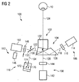
装置100の第2の実施形態が図2に示される。第2の実施形態による装置100は、放射インターフェース102が光ブランチカプラ104の出力面である(図1に示されるインターフェース用光学部品126を含まない)という点で、第1の実施形態と異なる。装置100は、照明ユニット106、固定ユニット108、波面ユニット110及びOCTユニット112を更に含む。波面ユニット110は、(レンズレットアレイ158及びイメージセンサー159の代わりとして)デジタル波面センサー172を含む。デジタル波面センサー172は、取得された放射を(例えば回折によって)4つのビーム176に複製するように適合された2次元回折格子又は格子174を含む。4つのビーム176はそれらの波面に関して本質的に同一である。各ビーム176は、横方向にずれた方向に沿って(すなわち、サイドブランチ154の伝播方向に対して小さい角度で)伝播する。4つのオフセットビーム176の伝播方向は、サイドブランチ154に対して垂直な平面において左下方向、右下方向、左上方向及び右上方向にずらされる(図2にはそのうちの二つが示される)。検出器172は、回折格子又は格子174と接する位置から生じた、別々にずらされたビーム176の干渉信号を検出するように適合される。干渉信号は、波面の相対的位相差、局所的な傾き又は局所的な変化を表す。
A second embodiment of the
図3は、眼科用放射のための装置100の第3の実施形態を概略的に示す。装置100は、光路124を決定する放射インターフェース102、光ブランチカプラ104、並びに、複数の眼科ユニット106、108、110及び112を含む。眼科ユニットのそれぞれは、第1の実施形態又は第2の実施形態を参照して上述された眼科ユニットに対応させることができる。
FIG. 3 schematically shows a third embodiment of an
図3に示される第3の実施形態による光ブランチカプラ104は、上述したブランチカプラ104とは異なる。第3の実施形態によると、光ブランチカプラは第1の部分透過ミラー178及び第2の部分透過ミラー180を含む。第1の部分透過ミラー178は、第1の部分透過層で覆われた平面状のガラス板を含む。第1の部分透過ミラー178又は第1の部分透過層の透過率T1(λ)は、出力する放射又は取得される放射の波長λに依存する。第1の透過率T1は、750nmより短い波長に対して本質的に100%である。一般に、本質的に100%に等しいとは、90%より大きいこと、例えば95%より大きいことを意味する。第1の透過率T1は約750nmで急激に低下する。例えば、第1の透過率T1は、710nmから790nmのスペクトル範囲内で90%より大きい値から10%未満の値に低下する。第1の透過率T1は、790nmより長い波長λで本質的に0%である。一般に、本質的に0%に等しいとは、10%未満、例えば5%未満を意味する。
The
第2の部分透過ミラー180は、第2の部分透過層で覆われた平面状のガラス板を含む。第2の部分透過ミラー180又は第2の部分透過層の第2の透過率T2(λ)は、出力する放射又は取得される放射の波長λに依存する。第2の透過率T2は、500nm未満の波長で本質的に0%に等しい。第2の透過率T2は、約500nmで急激に増大する。第2の透過率T2は、500nmより長い波長に対して本質的に100%に等しい。第2の透過率T2は、450nmから550nmのスペクトル範囲内で10%未満の値から90%より大きい値に増大する。第1の及び第2の部分透過ミラー178、180の両方の吸収率は、無視できる範囲、又は2%未満、例えば1%未満である。
The second
第1の部分透過ミラー178は、光路124上に配置される。第1の部分透過ミラー178において、光路124は、第1の部分透過ミラー178の法線に対する入射角αを囲む。第2の部分透過ミラー180は、第1の部分透過ミラー178を通過する取得された放射のために、第1の部分透過ミラー178に続いて光路124上に配置される。第2の部分透過ミラー180において、光路124は、第2の透過ミラー180の法線に対する入射角βを囲む。図3に示される第3の実施形態において、入射角α及びβは本質的に45°に等しい。
The first
拡張された実施形態において、一つ又は全ての部分反射ミラー178、180は回旋可能である。一つ又は二つのアクチュエータは、回旋可能な部分透過ミラー178及び180のそれぞれに機械的に接続される。アクチュエータのそれぞれは、回旋可能な部分透過ミラーを第1の角度位置及び第2の角度位置の間で回旋させるように適合される。制御装置140は、一つ又は複数のアクチュエータを制御するように適合される。第1の角度位置において、(第1の又は第2の)回旋可能な部分透過ミラーは、光路124上で取得された放射を第1の光サブブランチに方向付ける。逆も又同様である。第2の角度位置において、(第1の又は第2の)回旋可能な部分透過ミラーは、光路124上で取得された放射を第2の光サブブランチに方向付ける。逆も又同様である。異なる眼科ユニット又は異なる眼科サブユニットは、光サブブランチのそれぞれに接続される。これに代わって、第1のサブブランチはビームダンプに接続され、第2のサブブランチは、眼科ユニット106、108、110、112のうちの一つ以上に接続される。第1の角度位置において、取得された放射は、ビームダンプに接続された第1のサブブランチに方向付けられる。第1の角度位置は、例えば、取得された放射が高強度の場合に、眼科ユニットのうち一つ以上を保護するための保護状態として機能する。
In the expanded embodiment, one or all of the partially reflecting
このように、第3の実施形態による光ブランチカプラ104は、光路124上で取得された放射のうち、500nm未満の波長を有する放射を第1の光ブランチ118に、500nmから750nmのスペクトル範囲内の波長を有する放射を第2の光ブランチ120に、750nmより長い波長を有する放射を第3の光ブランチ122にスペクトル的に分割する。
As described above, the
(第3の実施形態に関して上述した)波長依存性の第1の透過率T1及び第2の透過率T2によるスペクトル分割は、第1の実施形態又は第2の実施形態によっても実現可能であり、例えば(図1に示される)光インターフェース136は、上記ミラー178の光透過率及び光反射率と類似して、取得された放射を分割することができる。
Spectral division by wavelength-dependent first transmittance T 1 and second transmittance T 2 (described above with respect to the third embodiment) can also be realized by the first embodiment or the second embodiment. For example, the optical interface 136 (shown in FIG. 1) can split the acquired radiation, similar to the light transmittance and light reflectance of the
図4は、第1の及び第2の実施形態のそれぞれに用いられる光ブランチカプラ104の更なる詳細を概略的に図示する。光ブランチカプラ104は、3つのガラスプリズム128、130及び132を含む。ガラスプリズム128及び130の間の第1の光インターフェース134は、第1のダイクロイック層を含む。ガラスプリズム130及び132の間の第2の光インターフェース136は、第2のダイクロイック層を含む。第2のダイクロイック層は、第1のスペクトル範囲及び第2のスペクトル範囲において透過性である。第3のスペクトル範囲内の光路124上で取得された放射は、第2のダイクロイック層から反射される。第2のダイクロイック層を透過可能なスペクトル範囲の放射成分は、ガラスプリズム130に入射する。第1の成分は第2のダイクロイック層から反射される。反射された第1の成分は、第1の光ブランチ118を定める。第2の成分は、第1のダイクロイック層(第1の光インターフェース134等)を通過する。このように、第2の成分は、第2の光ブランチ120を定める。第2のダイクロイック層(第2の光インターフェース136等)から反射された第3の成分は、第3の光ブランチ122を定める。
FIG. 4 schematically illustrates further details of the
図5a及び図5bは、光ブランチカプラ104の代替的なプリズムの形状を概略的に示す。光ブランチカプラ104は、4つのガラスプリズム128、129、130及び132を含む。光インターフェース134、135及び136は、異なるダイクロイック層を含む。図5aに示されるように、上記複数の異なるダイクロイック層は、第1のスペクトル範囲内で出力する放射、第2のスペクトル範囲内で出力する放射及び第3のスペクトル範囲内で出力する放射を1本の光路中に合成するように選択された、それぞれ異なるスペクトル透過率及びスペクトル反射率を有する。図5bは、それに対応する、1本の光路124から取得された放射の3つの異なる光学ブランチ118、120及び122へのスペクトル範囲に応じた分解を示す。
FIGS. 5 a and 5 b schematically illustrate alternative prism shapes for the
上述の実施形態では3つの光ブランチ118、120及び122の場合について説明されてきたが、図6a及び図6bは、多様な数の光ブランチのための光ブランチカプラ104の斜視図を示す。図6aの左半分には、(光ブランチカプラ104として)多分岐ダイクロイックプリズムが示される。多分岐ダイクロイックプリズムは、3つの光ブランチ118、120及び122を提供する。光ブランチの数は、ダイクロイックプリズムの「チャネル」の数とも呼ばれる。装置100の縮小された実施形態のため、図6aの右半分に示されるような、2つの光ブランチ118及び120を提供するダイクロイックプリズムが用いられる。図6bの右半分は、(光ブランチカプラ104として)4つの光ブランチ118、120、122及び123を提供する多分岐ダイクロイックプリズムを示す。図6bの左半分には(光ブランチカプラ104として)5つの光ブランチ118、119、120、122及び123を提供する別の多分岐ダイクロイックプリズムが示される。
Although the above embodiment has been described for the case of three
光カプラにおける異なる光ブランチの光路長は、それぞれ異なっている。光路長は、ガラスプリズムの又はダイクロイック結晶プリズムの長さ若しくは他の直線的な寸法に依存して、プリズムの形状及び屈折率によって予め決定される。屈折率は、放射の偏光に依存し得る。異なる光路長によって、眼球10の前部及び背部等の空間的に分離された構造を装置100によって同時に検出することが可能になる。また、プリズムは、光インターフェース(光インターフェース134、135及び136等)において互いに直接接触する、又は、結合される。これによって、装置100のコンパクトかつ頑丈な設計が可能になる。
The optical path lengths of the different optical branches in the optical coupler are different from each other. The optical path length is predetermined by the prism shape and refractive index, depending on the length of the glass prism or dichroic crystal prism or other linear dimensions. The refractive index can depend on the polarization of the radiation. Different optical path lengths allow the
これに加えて、装置100は、眼科ユニットの一つとして治療ユニットを含むことができる。治療ユニットは、(装置100の出力する放射として)治療用放射を一つ以上の光ブランチに接続するように適合される。
In addition, the
特に、治療ユニットは、レーザー補助による角膜切削形成術(Laser−Assisted In−Situ Keratomileusis)ユニット、すなわちLASIKユニットとすることができる。LASIKユニットは、レーザー、例えば、屈折矯正手術のために出力する紫外線を生成するように適合されたエキシマレーザーを含む。より具体的には、治療ユニットは、フェムト秒レンティクル抽出(femtosecond lenticle extraction)ユニット、すなわちFLExユニットとすることができる。FLExユニットは、レーザー、例えば、赤外線又は紫外線を出力するように適合されたフェムト秒レーザーを含む。更に、治療ユニットは、角膜形成又は上皮のアブレーションのために使用されることができる。更なる利点として、他の眼科ユニットは、治療のリアルタイムのモニタリングを実質的に同時に提供することができる。これに代わって、又はこれに加えて、治療ユニットは、エキシマレーザー又はフェムト秒レーザーを含む。 In particular, the treatment unit can be a laser-assisted in-situ keratomileus unit, ie a LASIK unit. The LASIK unit includes a laser, eg, an excimer laser adapted to generate ultraviolet light that is output for refractive surgery. More specifically, the treatment unit may be a femtosecond lenticle extraction unit, ie, a FLEX unit. The FLEX unit includes a laser, eg, a femtosecond laser adapted to output infrared or ultraviolet light. In addition, the therapeutic unit can be used for corneal formation or epithelial ablation. As a further advantage, other ophthalmic units can provide real-time monitoring of treatment substantially simultaneously. Alternatively or additionally, the treatment unit includes an excimer laser or a femtosecond laser.
以上の説明から明らかになったように、本装置は、(診断及び/又は治療を含む)複数の異なる眼科技術をよりコンパクトな装置に統合することができる。この装置は、異なる眼科技術による処理を、より速く完了することができる。眼科ユニットによって提供される眼科技術は、異なるスペクトル範囲内の異なる波長で動作する任意の技術を含むことができる。 As will become apparent from the foregoing description, the device can integrate a plurality of different ophthalmic techniques (including diagnosis and / or treatment) into a more compact device. This device can complete the processing by different ophthalmic techniques faster. The ophthalmic technology provided by the ophthalmic unit can include any technology that operates at different wavelengths within different spectral ranges.
Claims (15)
眼球に対して方向付け可能な光路上で出力する放射及び取得される放射のうち少なくとも一つに適合された放射インターフェースと、
出力する放射を複数の光ブランチから前記光路に接続し、取得した放射を前記光路から前記複数の光ブランチに接続し、前記取得した放射はスペクトル的に前記複数の光ブランチに分割され、該光ブランチのそれぞれが異なるスペクトル範囲を有するように適合された光ブランチカプラと、
それぞれが前記光ブランチのうち一つ以上と接続するように配置された複数の眼科ユニットとを含み、
前記眼科ユニットは、光干渉断層撮影測定を実行するように適合された光干渉断層撮影ユニット、すなわちOCTユニットと、前記取得した放射の波面を測定するように適合された波面ユニットとを含み、
前記OCTユニット及び前記波面ユニットは、広帯域光源を共有し、前記波面ユニットは、更に、狭帯域フィルターを前記広帯域光源に選択的に適用するように適合されたものである、装置。 A device for ophthalmic radiation,
A radiation interface adapted to at least one of the radiation output on the optical path directable with respect to the eyeball and the acquired radiation;
Connecting output radiation from a plurality of optical branches to the optical path, connecting acquired radiation from the optical path to the plurality of optical branches, the acquired radiation being spectrally divided into the plurality of optical branches; An optical branch coupler adapted to have each of the branches have a different spectral range;
A plurality of ophthalmic units, each arranged to connect with one or more of the optical branches,
The ophthalmic unit comprises an optical coherence tomography unit adapted to perform optical coherence tomography measurements, i.e. an OCT unit, and a wavefront unit adapted to measure the wavefront of the acquired radiation;
The OCT unit and the wavefront unit share a broadband light source, and the wavefront unit is further adapted to selectively apply a narrowband filter to the broadband light source.
Applications Claiming Priority (1)
| Application Number | Priority Date | Filing Date | Title |
|---|---|---|---|
| PCT/EP2011/006614 WO2013097885A1 (en) | 2011-12-30 | 2011-12-30 | An integrated device for ophthalmology |
Publications (2)
| Publication Number | Publication Date |
|---|---|
| JP2015508307A JP2015508307A (en) | 2015-03-19 |
| JP6027138B2 true JP6027138B2 (en) | 2016-11-16 |
Family
ID=45443068
Family Applications (1)
| Application Number | Title | Priority Date | Filing Date |
|---|---|---|---|
| JP2014549367A Active JP6027138B2 (en) | 2011-12-30 | 2011-12-30 | Ophthalmic integrated device |
Country Status (13)
| Country | Link |
|---|---|
| US (2) | US20140347629A1 (en) |
| EP (1) | EP2797492B1 (en) |
| JP (1) | JP6027138B2 (en) |
| KR (1) | KR101684566B1 (en) |
| CN (1) | CN104066370B (en) |
| AU (1) | AU2011384708B2 (en) |
| CA (1) | CA2859120C (en) |
| DK (1) | DK2797492T3 (en) |
| ES (2) | ES2658304T3 (en) |
| IN (1) | IN2014KN01371A (en) |
| PL (1) | PL2797492T3 (en) |
| PT (1) | PT2797492T (en) |
| WO (1) | WO2013097885A1 (en) |
Families Citing this family (25)
| Publication number | Priority date | Publication date | Assignee | Title |
|---|---|---|---|---|
| EP2459051B1 (en) | 2009-08-02 | 2022-03-16 | Tel HaShomer Medical Research Infrastructure and Services Ltd. | System and method for objective chromatic perimetry analysis using pupillometer |
| US9622911B2 (en) | 2010-09-30 | 2017-04-18 | Cxl Ophthalmics, Llc | Ophthalmic treatment device, system, and method of use |
| WO2013148896A1 (en) | 2012-03-29 | 2013-10-03 | Cxl Ophthalmics, Llc | Ocular treatment solutions, delivery devices and delivery augmentation methods |
| WO2013149075A1 (en) | 2012-03-29 | 2013-10-03 | Cxl Ophthalmics, Llc | Compositions and methods for treating or preventing diseases associated with oxidative stress |
| EP3575860A1 (en) | 2012-06-01 | 2019-12-04 | NKT Photonics A/S | A supercontinuum light source, a system and a method of measuring |
| DE102012019474A1 (en) * | 2012-09-28 | 2014-04-03 | Carl Zeiss Meditec Ag | Device for the reliable determination of biometric measurements of the entire eye |
| US9538911B2 (en) * | 2013-09-19 | 2017-01-10 | Novartis Ag | Integrated OCT-refractometer system for ocular biometry |
| WO2015063598A1 (en) | 2013-10-30 | 2015-05-07 | Tel Hashomer Medical Research Infrastructure And Services Ltd. | Pupillometers and systems and methods for using a pupillometer |
| US9918627B2 (en) | 2014-05-06 | 2018-03-20 | David Huang | Aqueous cell differentiation in anterior uveitis using optical coherence tomography |
| KR102282141B1 (en) | 2014-09-02 | 2021-07-28 | 삼성전자주식회사 | Semiconductor light emitting device |
| CN108025011A (en) | 2015-07-21 | 2018-05-11 | 艾维德洛公司 | With the system and method for photosensitizing agents eyes |
| AU2015404164A1 (en) | 2015-07-27 | 2018-01-18 | Amo Wavefront Sciences, Llc | Optical imaging and measurement systems and methods for cataract surgery and treatment planning |
| US9427156B1 (en) * | 2015-08-27 | 2016-08-30 | Ovitz Corporation | Devices and methods for wavefront sensing and corneal topography |
| US10188481B2 (en) * | 2015-12-17 | 2019-01-29 | Novartis Ag | Beam guide for ophthalmic surgical illumination |
| CN105615825A (en) * | 2015-12-28 | 2016-06-01 | 上海美沃精密仪器有限公司 | Cornea surface contour obtaining system and use method thereof |
| EP3402388B1 (en) | 2016-01-12 | 2021-02-17 | Accutome, Inc. | System and method for performing objective perimetry and diagnosis of patients with retinitis pigmentosa and other ocular diseases |
| DE102016102209B4 (en) * | 2016-02-09 | 2021-08-26 | Carl Zeiss Jena Gmbh | Optical arrangement and lens connection with multi-way prism |
| DE102017203010A1 (en) * | 2017-02-24 | 2018-08-30 | Carl Zeiss Meditec Ag | Method and device for the high-resolution topography of the cornea of an eye |
| WO2019169184A1 (en) * | 2018-02-28 | 2019-09-06 | DWFritz Automation, Inc. | Metrology system |
| JP7352411B2 (en) * | 2019-08-22 | 2023-09-28 | キヤノン株式会社 | Imaging device |
| JP2022169819A (en) * | 2019-10-02 | 2022-11-10 | 株式会社ニコン | Ophthalmologic apparatus |
| WO2021066047A1 (en) * | 2019-10-02 | 2021-04-08 | 株式会社ニコン | Ophthalmological device |
| GB202002009D0 (en) * | 2020-02-13 | 2020-04-01 | Univ Liverpool | An imaging device |
| CN113229777B (en) * | 2021-04-07 | 2022-09-23 | 上海美沃精密仪器股份有限公司 | Visual quality analyzer |
| CN117825279A (en) * | 2024-03-04 | 2024-04-05 | 江苏金视传奇科技有限公司 | Full-field sweep-frequency optical coherence tomography system capable of achieving parallel acquisition |
Family Cites Families (26)
| Publication number | Priority date | Publication date | Assignee | Title |
|---|---|---|---|---|
| US5048946A (en) * | 1990-05-15 | 1991-09-17 | Phoenix Laser Systems, Inc. | Spectral division of reflected light in complex optical diagnostic and therapeutic systems |
| US6198540B1 (en) * | 1997-03-26 | 2001-03-06 | Kowa Company, Ltd. | Optical coherence tomography have plural reference beams of differing modulations |
| US5914817A (en) * | 1998-05-15 | 1999-06-22 | Optical Coating Laboratory, Inc. | Thin film dichroic color separation filters for color splitters in liquid crystal display systems |
| US7364296B2 (en) * | 2002-06-12 | 2008-04-29 | University Of Rochester | Method and apparatus for improving both lateral and axial resolution in ophthalmoscopy |
| CA2390072C (en) * | 2002-06-28 | 2018-02-27 | Adrian Gh Podoleanu | Optical mapping apparatus with adjustable depth resolution and multiple functionality |
| US8269966B2 (en) * | 2005-03-03 | 2012-09-18 | Qiagen Lake Constance Gmbh | Fluorescence meter |
| US7805009B2 (en) * | 2005-04-06 | 2010-09-28 | Carl Zeiss Meditec, Inc. | Method and apparatus for measuring motion of a subject using a series of partial images from an imaging system |
| US7391520B2 (en) * | 2005-07-01 | 2008-06-24 | Carl Zeiss Meditec, Inc. | Fourier domain optical coherence tomography employing a swept multi-wavelength laser and a multi-channel receiver |
| JP2009507256A (en) * | 2005-09-02 | 2009-02-19 | カラーリンク・インコーポレイテッド | Polarizing beam splitter and combiner |
| WO2007065670A2 (en) * | 2005-12-06 | 2007-06-14 | Carl Zeiss Meditec Ag | Interferometric sample measurement |
| US7445335B2 (en) * | 2006-01-20 | 2008-11-04 | Clarity Medical Systems, Inc. | Sequential wavefront sensor |
| US7758189B2 (en) | 2006-04-24 | 2010-07-20 | Physical Sciences, Inc. | Stabilized retinal imaging with adaptive optics |
| US7648242B2 (en) * | 2006-05-01 | 2010-01-19 | Physical Sciences, Inc. | Hybrid spectral domain optical coherence tomography line scanning laser ophthalmoscope |
| US20070291277A1 (en) * | 2006-06-20 | 2007-12-20 | Everett Matthew J | Spectral domain optical coherence tomography system |
| US7864331B2 (en) * | 2006-11-17 | 2011-01-04 | Fujifilm Corporation | Optical coherence tomographic imaging apparatus |
| DE102007017599A1 (en) * | 2007-04-13 | 2008-10-16 | Carl Zeiss Meditec Ag | Apparatus and method for axial length measurement with extended measurement function in the anterior segment of the eye |
| US7832864B2 (en) * | 2007-06-15 | 2010-11-16 | The Arizona Board Of Regents On Behalf Of The University Of Arizona | Inverse optical design |
| JP5199031B2 (en) * | 2008-11-05 | 2013-05-15 | 株式会社ニデック | Ophthalmic imaging equipment |
| JP5279524B2 (en) * | 2009-01-22 | 2013-09-04 | キヤノン株式会社 | Optical tomographic imaging apparatus and optical tomographic imaging method |
| EP2891452B1 (en) * | 2009-03-26 | 2021-11-03 | Alcon Inc. | Ocular modeling methods and apparatus |
| WO2010129544A1 (en) * | 2009-05-04 | 2010-11-11 | Duke University | Methods and computer program products for quantitative three-dimensional image correction and clinical parameter computation in optical coherence tomography |
| JP5645445B2 (en) * | 2009-05-22 | 2014-12-24 | キヤノン株式会社 | Imaging apparatus and imaging method |
| JP5610706B2 (en) * | 2009-05-22 | 2014-10-22 | キヤノン株式会社 | Imaging apparatus and imaging method |
| JP5743425B2 (en) * | 2010-04-30 | 2015-07-01 | キヤノン株式会社 | Ophthalmic apparatus and method for controlling ophthalmic apparatus |
| CA2808326A1 (en) * | 2010-06-01 | 2011-12-08 | Jay Wei | Method and apparatus for enhanced eye measurement |
| JP5704841B2 (en) * | 2010-06-10 | 2015-04-22 | キヤノン株式会社 | LIGHT SOURCE DEVICE AND IMAGING DEVICE USING THE SAME |
-
2011
- 2011-12-30 AU AU2011384708A patent/AU2011384708B2/en active Active
- 2011-12-30 ES ES11804503.8T patent/ES2658304T3/en active Active
- 2011-12-30 US US14/368,782 patent/US20140347629A1/en not_active Abandoned
- 2011-12-30 KR KR1020147021537A patent/KR101684566B1/en active IP Right Grant
- 2011-12-30 WO PCT/EP2011/006614 patent/WO2013097885A1/en active Application Filing
- 2011-12-30 EP EP11804503.8A patent/EP2797492B1/en active Active
- 2011-12-30 CN CN201180076177.4A patent/CN104066370B/en active Active
- 2011-12-30 CA CA2859120A patent/CA2859120C/en active Active
- 2011-12-30 IN IN1371KON2014 patent/IN2014KN01371A/en unknown
- 2011-12-30 PT PT118045038T patent/PT2797492T/en unknown
- 2011-12-30 PL PL11804503T patent/PL2797492T3/en unknown
- 2011-12-30 ES ES14002566.9T patent/ES2655848T3/en active Active
- 2011-12-30 DK DK11804503.8T patent/DK2797492T3/en active
- 2011-12-30 JP JP2014549367A patent/JP6027138B2/en active Active
-
2017
- 2017-10-05 US US15/725,978 patent/US10582851B2/en active Active
Also Published As
| Publication number | Publication date |
|---|---|
| ES2658304T3 (en) | 2018-03-09 |
| AU2011384708A1 (en) | 2014-07-17 |
| CA2859120C (en) | 2018-04-03 |
| PT2797492T (en) | 2018-01-24 |
| CN104066370A (en) | 2014-09-24 |
| KR20140116461A (en) | 2014-10-02 |
| US10582851B2 (en) | 2020-03-10 |
| CN104066370B (en) | 2016-10-19 |
| US20140347629A1 (en) | 2014-11-27 |
| DK2797492T3 (en) | 2018-02-05 |
| AU2011384708B2 (en) | 2015-01-22 |
| PL2797492T3 (en) | 2018-03-30 |
| JP2015508307A (en) | 2015-03-19 |
| ES2655848T3 (en) | 2018-02-21 |
| CA2859120A1 (en) | 2013-07-04 |
| KR101684566B1 (en) | 2016-12-08 |
| IN2014KN01371A (en) | 2015-10-16 |
| EP2797492A1 (en) | 2014-11-05 |
| WO2013097885A1 (en) | 2013-07-04 |
| US20180028060A1 (en) | 2018-02-01 |
| EP2797492B1 (en) | 2017-12-06 |
Similar Documents
| Publication | Publication Date | Title |
|---|---|---|
| JP6027138B2 (en) | Ophthalmic integrated device | |
| US20210101020A1 (en) | Systems and methods for applying and monitoring eye therapy | |
| US6806963B1 (en) | Method and device for measuring the optical properties of at least two regions located at a distance from one another in a transparent and/or diffuse object | |
| TWI520712B (en) | Apparatus and method for operating a real time large diopter range sequential wavefront sensor | |
| WO2021134087A1 (en) | Optical coherence tomography patient alignment system for home based ophthalmic applications | |
| JP7024295B2 (en) | Awareness-based optometry device | |
| EP2815694B1 (en) | An integrated device for ophthalmology | |
| JP6841091B2 (en) | Subjective optometry device | |
| JP6686380B2 (en) | Subjective optometry device and subject optometry program | |
| JP7375332B2 (en) | Optometry equipment and programs |
Legal Events
| Date | Code | Title | Description |
|---|---|---|---|
| A977 | Report on retrieval |
Free format text: JAPANESE INTERMEDIATE CODE: A971007 Effective date: 20150721 |
|
| A131 | Notification of reasons for refusal |
Free format text: JAPANESE INTERMEDIATE CODE: A131 Effective date: 20150804 |
|
| A521 | Request for written amendment filed |
Free format text: JAPANESE INTERMEDIATE CODE: A523 Effective date: 20151030 |
|
| A131 | Notification of reasons for refusal |
Free format text: JAPANESE INTERMEDIATE CODE: A131 Effective date: 20160329 |
|
| A521 | Request for written amendment filed |
Free format text: JAPANESE INTERMEDIATE CODE: A523 Effective date: 20160602 |
|
| TRDD | Decision of grant or rejection written | ||
| A01 | Written decision to grant a patent or to grant a registration (utility model) |
Free format text: JAPANESE INTERMEDIATE CODE: A01 Effective date: 20160913 |
|
| A61 | First payment of annual fees (during grant procedure) |
Free format text: JAPANESE INTERMEDIATE CODE: A61 Effective date: 20161013 |
|
| R150 | Certificate of patent or registration of utility model |
Ref document number: 6027138 Country of ref document: JP Free format text: JAPANESE INTERMEDIATE CODE: R150 |
|
| R250 | Receipt of annual fees |
Free format text: JAPANESE INTERMEDIATE CODE: R250 |
|
| S111 | Request for change of ownership or part of ownership |
Free format text: JAPANESE INTERMEDIATE CODE: R313113 |
|
| R350 | Written notification of registration of transfer |
Free format text: JAPANESE INTERMEDIATE CODE: R350 |
|
| R350 | Written notification of registration of transfer |
Free format text: JAPANESE INTERMEDIATE CODE: R350 |
|
| R250 | Receipt of annual fees |
Free format text: JAPANESE INTERMEDIATE CODE: R250 |
|
| R250 | Receipt of annual fees |
Free format text: JAPANESE INTERMEDIATE CODE: R250 |
|
| R250 | Receipt of annual fees |
Free format text: JAPANESE INTERMEDIATE CODE: R250 |
|
| R250 | Receipt of annual fees |
Free format text: JAPANESE INTERMEDIATE CODE: R250 |